1
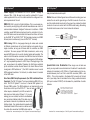
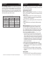
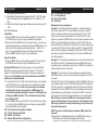
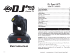
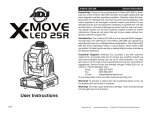
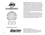
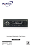
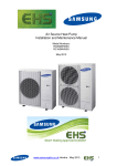
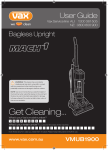
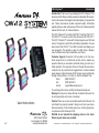
CW-12 System™ Introduction
Introduction: Thank you for purchasing the CW-12 System™ by
American DJ®. Please carefully read and understand the instructions in this manual thoroughly before attempting to operate this
unit. These instructions contain important safety information
regarding the use and maintenance of this unit. Please keep this
manual with the unit, for future reference.
The CW-12 System™ consists of a DCW 4™ and four CW-12’s™.
The DCW 4™ is used to control the American DJ® CW-12’s™.
The CW-12 System™ comes with 9 fade programs, and 20 fixed
colors. The speed in which this unit fades is adjustable. You can
also connect the DCW 4™ to a DMX controller and design your
own programs. This system is great for retail stores, displays,
mood, architectural, interior decoration, and clubs.
Customer Support: American DJ® provides a toll free customer support line, to provide set up help and to answer any
question should you encounter problems during your set up or
initial operation. You may also visit us on the web at www.americandj.com for any comments or suggestions. For service related
issue please contact American DJ®. Service Hours are Monday
through Friday 9:00 a.m. to 5:00 p.m. Pacific Standard Time.
Voice:
(800) 322-6337
Fax: (323) 582-2941
E-mail: [email protected]
To purchase parts online visit http://parts.americandj.com
Warning! To prevent or reduce the risk of electrical shock or fire,
do not expose this unit to rain or moisture.
User Instructions
American DJ
®
9/07
4295 Charter Street
Los Angeles, CA. 90058
www.americandj.com
Caution! There are no user serviceable parts inside this unit. Do
not attempt any repairs yourself, doing so will void your manufactures warranty. In the unlikely event your unit may require service please contact American DJ®.
PLEASE do not discard the shipping carton in the trash.
Please recycle when ever possible.
American DJ® - www.americandj.com - CW-12 System™ Instruction Manual Page 2
CW-12 System™ •
•
•
•
•
•
•
•
•
•
Features
3 Operation modes: Fixed Color, Fade Programs, DMX Control
20 Fixed Colors
9 Fade Programs with Adjustable Fade Speed
2 DMX Channel Modes: 3 Channel Mode & 5 Channel Mode
Dimming & Strobing in 5 Channel Mode
Control Each Light Individually or All Together in DMX Mode
Master/Slave Configuration
Light Weight, Compact Case Design
Built-In Mounting Plate on Controller
Low Power Consumption
CW-12 System™ Unpacking
Every CW-12 System™ has been thoroughly tested and has been
shipped in perfect operating condition. Carefully check the shipping carton for damage that may have occurred during shipping.
If the carton appears to be damaged, carefully inspect your unit
for damage and be sure all accessories necessary to operate the
unit have arrived intact. In the event damage has been found or
parts are missing, please contact our toll free customer support
number for further instructions. Please do not return this unit to
your dealer without first contacting customer support.
CW-12 System™
Warranty Registration
The CW-12’s carry a 3 Year (1095 Days) limited warranty. The
DCW 4™ carries a 1 Year (365 Day) limited warranty. We recommend you fill out the enclosed warranty card to validate your
purchase. All returned service items whether under warranty or
not, must be freight pre-paid and accompany a return authorization (R.A.) number. If the unit is under warranty, you must
provide a copy of your proof of purchase invoice. Please contact American DJ® customer support for a R.A. number.
American DJ® - www.americandj.com - CW-12 System™ Instruction Manual Page 3
CW-12 System™ Precautions
•Do not spill water or other liquids into or on to your unit.
•Be sure that the local power outlet matches that of the required voltage for your unit.
•Do not attempt to operate this unit if the power supply cord has
been frayed or broken. Please route your power supply cord away
from foot traffic.
•Disconnect from main power before making any type of connection.
• There are no user serviceable parts inside.
•Never plug this unit in to a dimmer pack
•Always be sure to mount this unit in an area that will allow proper ventilation. Allow about 6” (15cm) between this device and a wall.
•Do not attempt to operate this unit if it becomes damaged in any way.
•Never operate this unit when it’s front cover is removed.
• To reduce the risk of electrical shock or fire, do not expose this unit rain or moisture
•This unit is intended for indoor use only, use of this product outdoors voids all warranties.
•During long periods of non-use, disconnect the unit’s main power.
•Always mount this unit in safe and stable matter.
•Power-Cord Protection - Power-supply cords should be routed so
they are not likely to be walked on or pinched by items placed upon or against them, paying particular attention to cords a plugs, convenience receptacles, and the point where they exit from the fixture.
• Cleaning -The fixture should be cleaned only as recommended by the manufacturer. Use a dry cloth to wipe down the CW-12 System™.
•Heat -The fixture should be situated away from heat sources such
as radiators, heat registers, stoves, or other appliances (including
amplifiers) that produce heat.
•The fixture should be serviced by qualified service personnel when:
A. The power-supply cord or the plug has been damaged.
B. Objects have fallen, or liquid has been spilled into the appliance.
C. The appliance has been exposed to rain or water.
D. The fixture does not appear to operate normally or exhibits a marked change in performance.
American DJ® - www.americandj.com - CW-12 System™ Instruction Manual Page 4
CW-12 System™ Set Up
CW-12 System™ Power Supply: The American DJ® CW-12 System™ voltage is
POWER
DMX+,DMX-,COMMON
cables. Do not use
the ground lug on the XLR connector. Do not connect the cable’s shield conductor to the ground lug or allow the shield
conductor to come in contact with the XLR’s outer casing. Grounding
the shield could cause a short circuit and erratic behavior.
tocol used by most lighting and controller manufactures as a form of
communication between intelligent fixtures and controllers. A DMX
controller sends DMX data instructions from the controller to the fixture. DMX data is sent as serial data that travels from fixture to fixture
via the DATA “IN” and DATA “OUT” XLR terminals located on all DMX
fixtures (most controllers only have a DATA “OUT” terminal).
REMOTE
CONTROL
INPUT
INPUT
OUTPUT
COMMON
DMX512 OUT
3-PIN XLR
1
2
3
American DJ® - www.americandj.com - CW-12 System™ Instruction Manual Page 5
1
2
DMX +
3
DMX -
3
1
DMX512 IN
3-PIN XLR
2
3
1
2
Figure 2
XLR Female Socket
XLR Male Socket
1 Ground
2 Cold
2 Cold
REMOTE
CONTROL
INPUT
SOUND
INPUT
OUTPUT
1 Ground
XLR Pin Configuration
Pin 1 = Ground
REMOTE
CONTROL
SOUND
3 Hot
INPUT
OUTPUT
INPUT
Pin 2
= Data Compliment (negative)
3 Hot
Pin 3 = Data True (positive)
Figure 3
Special Note: Line Termination. When longer runs of cable are
used, you may need to use a terminator on the last unit to avoid erratic
behavior. A terminator is a 90-120 ohm 1/4 watt resistor which is connected between pins 2 and 3 of a male XLR connector (DATA + and
DATA -). This unit is inserted in the female XLR connector of the last
unit in your daisy chain to terminate the line. Using a cable terminator
(ADJ part number Z-DMX/T) will decrease the possibilities of erratic
behavior.
POWER
Data Cable (DMX Cable) Requirements (For DMX and Master/Slave
Operation): The CW-12 System™ can be controlled via DMX-512 protocol. The CW-12 System™ can be a 3 channel DMX system or 5
Channel DMX system. The DMX address is set electronicallyCOMMON
using
the buttons on the top of the DCW 4™ . Your unit
and
your
DMX
conDMX
+
DMX512 OUT
3-PIN XLR
DMX troller require a standard 3-pin XLR connector for
data input and data output (Figure 1). If you are
making your own cables, be sure to use standard
two conductor shielded cable (This cable may be
purchased at almost all professional sound and
lighting stores). Your cables should be made with
a male and female XLR connector on either end of
the cable. Also remember that DMX cable must be
Figure 1
POWER
Notice: Be sure to follow
figures two and three when making your own
DMX512
DMX-512: DMX is short for Digital Multiplex. This is a universal pro-
SOUND
Set Up
daisy chained and cannot be split.
between 100v ~ 240v. Be sure to only use the included I.E.C. power
cable supplied with the unit, this cable matches the voltage and current requirements of the unit.
DMX Linking: DMX is a language allowing all makes and models
of different manufactures to be linked together and operate from a
single controller, as long as all fixtures and the controller are DMX
compliant. To ensure proper DMX data transmission, when using
several DMX fixtures try to use the shortest cable path possible. The
order in which fixtures are connected in a DMX line does not influence
the DMX addressing. For example; a fixture assigned a DMX address
of 1 may be placed anywhere in a DMX line, at the beginning, at the
end, or anywhere in the middle. Therefore, the first fixture controlled
by the controller could be the last fixture in the chain. When a fixture
is assigned a DMX address of 1, the DMX controller knows to send
DATA assigned to address 1 to that unit, no matter where
DMX512 it is located
DMX+,DMX-,COMMON
in the DMX chain.
POWER
3
1
2
DMX512 IN
3-PIN XLR
3
1
2
POWER
Termination reduces signal errors and
avoids signal transmission problems
and interference. It is always advisable
to connect a DMX terminal, (Resistance
120 Ohm 1/4 W) between PIN 2 (DMX-)
and PIN 3 (DMX +) of the last fixture.
Figure 4
American DJ® - www.americandj.com - CW-12 System™ Instruction Manual Page 6
Termination
avoids sign
and interfere
to connect a
120 Ohm 1/4
and PIN 3 (
CW-12 System™ Set Up
5-Pin XLR DMX Connectors. Some manufactures use 5-pin XLR
connectors for DATA transmission in place of 3-pin. 5-pin XLR fixtures
may be implemented in a 3-pin XLR DMX line. When inserting standard 5-pin XLR connectors in to a 3-pin line a cable adaptor must be
used, these adaptors are readily available at most electric stores. The
chart below details a proper cable conversion.
3-Pin XLR to 5-Pin XLR Conversion
Conductor
3-Pin XLR Female (Out)
5-Pin XLR Male (In)
Ground/Shield
Pin 1
Pin 1
Data Compliment (- signal)
Pin 2
Pin 2
Data True (+ signal)
Pin 3
Pin 3
Not Used
Pin 4 - Do Not Use
Not Used
Pin 5 - Do Not Use
CW-12 System™ Operation
Power Supply: The American DJ® CW-12 System’s ™ voltage is
100v ~ 240v. You do not have select the voltage, you can plug it into
a power source of either voltage.
Operating Modes and Set Up:
DCW 4™ and CW-12’s Set Up: This will allow you to control your
CW-12’s™ with the DCW 4™ controller. You can choose one of the 3
operating modes.
1. Start by connecting the CW-12’s™ to the DCW 4™. Attached to each CW-12™ is a Male 5-pin connector, use the attached cable to link the CW-12’s™ to the DCW 4™.
2. After you set up your complete system, switch on the power to the DCW 4™.
3. Press the MENU button to scroll through the different operating modes. Master-Slave Operation: This function will allow you to link CW12™ systems together but operate with one controller. The CW12’s™ can run either one of the fade programs or be set to a fixed
color . In Master-Slave operation one controller will act as the controlling unit and the others will react to the controlling units programs.
Any unit can act as a Master or as a Slave.
1. Using standard XLR microphone cables, daisy chain your units together via the XLR connector on the rear of the DCW 4™. Re-
member the Male XLR connector is the input and the Female XLR connector is the output. The first unit in the chain (master) will use the female XLR connector only - The last unit in the chain will use the male XLR connector only. For longer cable runs we suggest a terminator at the last fixture.
2. Select your Slave unit(s) and set the DMX address to “001”.
3. On the Master unit press the MENU button until S-- is displayed. Press the UP button until S21 is displayed, then press the MENU button to confirm.
4. Using the MENU button on the Master unit select your desired Fade program or Fixed Color. The Slave units will follow the Mas-
ter fixture.
Operating Modes:
S--: Set up Mode for DMX. There are two DMX channel modes and American DJ® - www.americandj.com - CW-12 System™ Instruction Manual Page 7
American DJ® - www.americandj.com - CW-12 System™ Instruction Manual Page 8
CW-12 System™ Operation cont.
options you can choose from.
F--: Fade Mode Choose desired programs from F01 - F09. The Fade time of the program can be adjusted from 1% - 99% (0.5 ~50 Sec).
C--: Fixed Color Mode Choose from 20 desired fixed colors from C01 - C20.
001: DMX addressing
Fade Mode:
1. Press the MENU button until the display reads F01. Press the UP or DOWN buttons until you find your desired fade program.
2. Press and hold the MENU button for at least 3 secs., you can now adjust the fade speed my pressing the UP and DOWN buttons. The
Fade time of the program can be adjusted from 1 - 99 (0.5 - 50 Sec). 1 being the fastest fade time, and 99 being the slowest.
Press the MENU button to confirm your adjustment.
Fixed Color Mode:
1. Press the MENU button until the display reads C01. Press the UP or DOWN buttons until you find your desired fixed color.
Universal DMX Control: This mode allows you to use a Elation®
DMX-512 controller to control the CW-12 System™. The CW-12
System™ has two DMX Channel modes, a 3 channel mode and 5
channel mode. Note: When you first use DMX mode, the DCW 4™
will be set to all default modes.
1. To control the CW-12s in DMX mode, follow the set-up procedures under DCW 4 Control, as well as the set-up procedures included with your DMX controller. Note: You must confirm you desired settings before the unit can connect to a DMX signal. You must confirm settings indivdually. Connect to a DMX signal by turning your DMX controller “On”, and disconnect by turning the controller “Off”
2. Press the MENU button on the DCW 4 until the LCD screen shows S--. Use the UP and DOWN buttons to choose your desired DMX options and DMX channel modes.
S10 - Control all fixtures together (default)
S11 - Control fixture individually
S20 - Master Off (default)
S21 - Master (Master/Slave configuration)
American DJ® - www.americandj.com - CW-12 System™ Instruction Manual Page 9
CW-12 System™ S30 - 3 Channel Mode (default)
S31 - 5 Channel Mode
S40 - Delay Off (default)
S41 - Delay On
Operation cont.
Examples of set up procedures:
Example 1: Controlling all fixtures together, is a default setting, so
you do not have to set it. You must decide if you want 3 channel
mode or 5 channel mode, and if you want the delay “On” or “Off”.
If you want 5 channel mode, press the UP button until S31 is displayed, now press the MENU button so that it goes to address mode.
Select your desired address, and finally connect to DMX. You now
have confirmed you setting. Now disconnect. If you want delay mode
on, press the UP button until the display reads S41. Press the MENU
button so that the addres is displayed, and connect to DMX. You are
now able to control all fixtures together in the 5 channel DMX mode,
with delay mode on.
Example 2: To control fixtures individually in a 3 channel mode. Press
the UP button until S11 is displayed, press the MENU button to go
to address mode, set address, and connect to DMX. Since 3 channel
mode is default you don’t have set it.
Example 3: You are set to 5 channel mode and controlling fixtures
individually. Now you want to control all fixtures together in a 3 channel mode.
Press the UP button so S10 is displayed. Press the MENU button, set
your address, and connect to DMX. Now disconnect DMX, press the
UP button so that S-- is displayed. Press the UP button so that S30
is displayed. Press the MENU button to go to address mode, set the
same address as you did before, and connect to DMX. You should
now be able to control all the fixtures together, in a 3 channel mode.
Note: When you connect to DMX your are saving and confirming your setting change. You can only save one change at a time,
this is why you have to connect, disconnect, go to your next setting and connect again.
NOTE: If you do not follow these procedures, DMX control will
not work.
3. See page11 for detailed description of the DMX traits. Use your DMX controller to activate the programs and chases.
American DJ® - www.americandj.com - CW-12 System™ Instruction Manual Page 10
CW-12 System™ Channel
Value
DMX Traits 3 Channel Mode
Function
1
0 - 255
STATIC RED
0
100%
2
0 - 255
STATIC GREEN
0
100%
3
0 - 255
CW-12 System™ Channel
Value
STATIC BLUE
0
100%
DMX Traits 5 Channel Mode
Function
1
0 - 255
STATIC RED
0
100%
2
0 - 255
STATIC GREEN
0
100%
3
0 - 255
4
0 - 255
0 - 255
Trouble Shooting
Listed below are a few common problems and solutions you should
try before contacting customer support.
Certain parts of a CW-12™ do not work;
1. Change the CW-12™.
The CW-12’s™ cannot be controlled by the DCW 4™;
1. Change the DCW 4™.
Neither the CW-12’s™ or DCW 4™ are working;
1. Change power outlets.
2. Change the DCW 4™
The CW-12’s™ are not functioning properly using a DMX
Controller;
1. Make sure you have followed the set up procedures correctly.
2. Check your DMX controller. Make sure the controller is working properley.
STATIC BLUE
0
100%
0
5
CW-12 System™
DIMMER
100%
STROBE
SLOW
FAST
American DJ® - www.americandj.com - CW-12 System™ Instruction Manual Page 11
American DJ® - www.americandj.com - CW-12 System™ Instruction Manual Page 12
CW-12 System™ Warranty
CW-12 System™ Notes
MANUFACTURER’S LIMITED WARRANTY
A. American DJ, Inc. hereby warrants, to the original purchaser, American DJ and American
Audio products to be free of manufacturing defects in material and workmanship for a prescribed
period from the date of purchase (see specific warranty period on reverse). This warranty shall be
valid only if the product is purchased within the United States of America, including possessions
and territories. It is the owner’s responsibility to establish the date and place of purchase by acceptable evidence, at the time service is sought.
B.
For warranty service you must obtain a Return Authorization number (RA#) before
sending back the product. Contact American DJ, Inc. Service Department at 800-322-6337. Send
the product only to the American DJ, Inc. factory. All shipping charges must be pre-paid. If the
requested repairs or service (including parts replacement) are within the terms of this warranty,
American DJ, Inc. will pay return shipping charges only to a designated point within the United
States. If the entire instrument is sent, it must be shipped in it’s original package. No accessories
should be shipped with the product. If any accessories are shipped with the product, American DJ,
Inc. shall have no liability whatsoever for loss of or damage to any such accessories, nor for the
safe return thereof.
C. This warranty is void if the serial number has been altered or removed; if the product is
modified in any manner which American DJ, Inc. concludes, after inspection, affects the reliability
of the product; if the product has been repaired or serviced by anyone other than the American DJ,
Inc. factory unless prior written authorization was issued to purchaser by American DJ, Inc.; if the
product is damaged because not properly maintained as set forth in the instruction manual.
D.
This is not a service contract, and this warranty does not include maintenance, cleaning
or periodic check-up. During the period specified above, American DJ, Inc. will replace defective parts at its expense with new or refurbished parts, and will absorb all expenses for warranty
service and repair labor by reason of defects in material or workmanship. The sole responsibility
of American DJ, Inc. under this warranty shall be limited to the repair of the product, or replacement thereof, including parts, at the sole discretion of American DJ. All products covered by this
warranty were manufactured after January 1, 1990, and bear identifying marks to that effect.
E.
American DJ, Inc. reserves the right to make changes in design and/or improvements
upon its products without any obligation to include these changes in any products theretofore
manufactured. No warranty, whether expressed or implied, is given or made with respect to any
accessory supplied with products described above. Except to the extent prohibited by applicable
law, all implied warranties made by American DJ, Inc. in connection with this product, including
warranties of merchantability or fitness, are limited in duration to the warranty period set forth
above. And no warranties, whether expressed or implied, including warranties of merchantability
or fitness, shall apply to this product after said period has expired. The consumer’s and/or Dealer’s
sole remedy shall be such repair or replacement as is expressly provided above; and under no
circumstances shall American DJ, Inc. be liable for any loss or damage, direct or consequential,
arising out of the use of, or inability to use, this product. This warranty is the only written warranty applicable to American DJ and American Audio Products and supersedes all prior warranties and written descriptions of warranty terms and
conditions heretofore published.
MANUFACTURER’S LIMITED WARRANTY PERIODS:
• All American Audio Products = 1-year (365 day) Limited Warranty (except V-Plus Series Amplifiers)
• All American Audio V-Plus Series Amplifiers = 3-year (1095 day) Limited Warranty
• American DJ Lighting and American DJ Branded Products = 1-year (365 day) Limited Warranty
(Such as: Special Effect Lighting, Intelligent Lighting, UV lighting, Strobes, Fog Machines, Bubble
Machines, Mirror Balls, Par Cans, Trussing, Lighting Stands etc. excluding Laser Products, lamps,
and Star Tec Series)
• American DJ Laser Products and Star Tec Products = 90-Day Limited Warranty
• American DJ L.E.D. Products = 3-year (1095 day) Limited Warranty (excluding motors which
have a 1-year (365 day Limited Warranty)
American DJ® - www.americandj.com - CW-12 System™ Instruction Manual Page 13
American DJ® - www.americandj.com - CW-12 System™ Instruction Manual Page 14
CW-12 System™ Specifications
Model: DCW 4™
Voltage*:
Dimensions:
Working Position:
Weight:
Warranty:
100v~240v 50/60Hz
8.26” (L) X 7.71” (W) X 2.55”(H)
210 (L) X 196 (W) X 65 (H) mm
Any Safe Position
3.0 lbs/ 1.8 Kgs.
1 Year (365 Days)
Model: CW-12™
LED’s:
Power Consumption:
Dimensions:
Working Position:
Weight:
Warranty:
12 x 1Watt LED’s in Each Light
4 Red, 4 Green, and 4 Blue
12W Max at Full Intensity
6.18” (L) X 4.5” (W) X 1.47”(H)
157 (L) X 123 (W) X 36 (H) mm
Any Safe Position
1.5 lbs/ 0.85 Kgs.
3 Year (1095 Days)
Please Note: Specifications and improvements in the design
of this unit and this manual are subject to change without any
prior written notice.
American DJ® - www.americandj.com - CW-12 System™ Instruction Manual Page 15
American DJ®
American DJ® World Headquarters:
4295 Charter Street Los Angeles, CA 90058 USA
Tel: 323-582-2650 / Fax: 323-582-2610
Web: www.americandj.com / E-mail: [email protected]