1
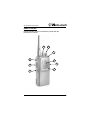
User’s Guide
SP-400 Series Portable
4/16 Channel VHF-FM Portable Transceiver
4/16 Channel UHF-FM Portable Transceiver
www.midlandradio.com
SP-400 Series User’s Guide
FCC RF EXPOSURE COMPLIANCE REQUIREMENTS
FOR OCCUPATIONAL USE ONLY
The Federal Communications Commission (FCC), within
its action in General Docket 93-62, November 7, 1997,
has adopted a safety standard for human exposure to
Radio Frequency (RF) electromagnetic energy emitted
by FCC regulated equipment. Midland Radio Corporation
subscribes to the same safety standard for the use of its
products. Proper operation of this radio will result in user
exposure far below the Occupational Safety and Health
Act (OSHA) and FCC limits.
DO NOT transmit for more than 50% of total use
time (50% duty cycle). Transmitting more than
50% of the time can cause FCC RF exposure
compliance requirements to be exceeded.
This radio is NOT approved for use by the
general population in an uncontrolled
environment. This radio is restricted to
occupational use, work related operations only,
where the radio operator must have the
knowledge to control the user’s exposure
conditions for satisfying the higher exposure
limit allowed for occupational use.
When transmitting, hold the radio in a vertical
position with its microphone 2 inches (5 cm)
away from your mouth. The radio is transmitting
when the red LED on the front of the radio is
illuminated. You can cause the radio to transmit
by pressing the PTT button on the radio. DO NOT
transmit while the radio is attached to your belt.
These are required operating conditions for
meeting FCC RF exposure compliance. Failure to
observe these restrictions means violation.
2
© 2005, Midland Radio Corporation
SP-400 Series User’s Guide
Contents
Conventions and Symbols in this Book ................................... 4
Disclaimer ................................................................................ 5
Safety ....................................................................................... 5
Introduction .............................................................................. 7
Radio models ....................................................................... 7
Radio features ...................................................................... 7
Radio Controls ......................................................................... 9
Top ....................................................................................... 9
Top ..................................................................................... 10
Front ................................................................................... 10
Side (right).......................................................................... 10
Side (left) ............................................................................ 10
Setup...................................................................................... 12
Unpacking .......................................................................... 12
Attaching and removing the antenna ................................. 12
Installing and removing the battery pack............................ 13
Installing and removing the belt clip ................................... 13
Charging the battery pack .................................................. 14
Basic Operation ..................................................................... 16
Turning the radio ON and OFF .......................................... 16
Adjusting the volume .......................................................... 16
Selecting the channel ......................................................... 16
Receiving transmissions from other radios ........................ 16
Monitoring the channel ....................................................... 18
Transmitting to other radios ............................................... 19
Selecting transmission power ............................................ 20
© 2005, Midland Radio Corporation
3
SP-400 Series User’s Guide
Sending a 2-tone/selective call or emergency call............. 20
Scanning channels ............................................................. 21
Advanced Operations ............................................................ 24
Operating hands-free ......................................................... 24
Using the scrambler ........................................................... 25
Editing your scan list .......................................................... 25
Care and Maintenance........................................................... 26
Using rechargeable battery packs...................................... 26
Cleaning your radio ............................................................ 30
Optional Accessories ............................................................. 30
Recommended accessories............................................... 31
Quick Reference .................................................................... 32
Controls function table........................................................ 32
Status LED table ................................................................ 33
Specifications......................................................................... 34
Warranty Statement ............................................................... 35
Conventions and Symbols in this Book
This symbol marks a “caution”. Cautions are special
notices which you should read and follow carefully to
avoid possible damage to your equipment and to avoid
potential danger to yourself or other people.
!
This symbol marks an “important point”. Important points
are specific instructions which should be followed closely
for proper operation.
This symbol marks a “note”. Notes are hints or tips which
offer additional information to help you.
4
© 2005, Midland Radio Corporation
SP-400 Series User’s Guide
Disclaimer
Midland Radio Corporation is committed to continuous quality
improvements, for this reason specifications may change without
prior notice.
Every effort has been made to ensure that the information in this
document is complete, accurate, and up-to-date. Midland
assumes no responsibility for the results of errors beyond its
control. The manufacturer of this equipment also cannot
guarantee that changes in the equipment made by unauthorized
people will not affect the transceiver’s performance or functions.
Safety
Your SP-400 series portable transceiver has been carefully
designed to give you years of safe, reliable performance. As with
all electrical equipment, however, there are a few basic
precautions you should take to avoid injury to yourself or
damage to the radio:
Read the instructions in this handbook carefully. Be
sure to save it for future reference.
Read and follow all warning and instruction labels
on the radio itself.
Do not carry the transceiver by the antenna. This
may damage the antenna or antenna terminal. Grasp it
by its base (not the tip!) when you need to attach or
remove the antenna.
Do not hold the radio with the antenna very close to,
or touching the body, while transmitting. The radio
will perform best if the microphone is 2-4 inches away
from the mouth and the radio is vertical.
Be sure the PTT button is not pressed when you do
not need to transmit.
© 2005, Midland Radio Corporation
5
SP-400 Series User’s Guide
Do not operate the radio near unshielded electrical
blasting caps or in an explosive atmosphere.
Do not transmit without the antenna attached to the
radio. Though designed for protection against damage,
damage to the transmitter may occur.
Respect the environmental conditions. The radio is
designed to operate in harsh environments, but avoiding
extended or unnecessary exposure will prolong the
service life.
Never attempt to disassemble or service the radio
yourself (aside from the routine maintenance described
in this handbook). It will immediately void the warranty
and you may cause damage requiring extensive repair
work. Always contact your local dealer or
communications coordinator for assistance.
Use only recommended accessories. Use of incorrect
accessories could seriously damage your handheld
transceiver.
Do not use your radio near water, or spill liquid of
any kind into it. If the transceiver gets wet immediately
dry it with a soft, clean cloth.
Switch the radio off before you clean it. Follow the
instructions in the “Care and maintenance” section.
Handle the battery properly. Follow the instructions in
the “Care and maintenance” section.
Make sure that your AC power source matches the
rating of the supplied battery charger AC adapter.
The above warning list is not intended to include all
hazards that may be encountered when using this radio.
6
© 2005, Midland Radio Corporation
SP-400 Series User’s Guide
Introduction
Congratulations! By choosing the Midland SP-400 series, you
have selected a professional grade portable radio. Its rugged
design will provide years of reliable service and its sophisticated
software allows many customizable options.
Radio models
There are four models in the SP-400 series portable radio line.
The models differ only by band of operation and channel
capacity.
SP-410 – 4 channel VHF, 148-174 MHz.
SP-420 – 4 channel UHF, 440-470 MHz.
SP-430 – 16 channel VHF, 148-174 MHz.
SP-440 – 16 channel UHF, 440-470 MHz.
Radio features
The SP-400 series is a programmable, synthesized radio with
the following features:
5 Easy to use – only five controls access all the
transceiver’s functions.
5 Up to sixteen channel capacity – simple and reliable
knob selection.
5 Programmable transmit power – select the transmit
power to maximize range or battery life. 1 or 5 watts (4
watts UHF) programmable per channel.
5 Channel scanning – flexible scan programming allows
the radio to search for signals on programmed channels.
Priority scan, priority transmit and priority lookback are
all programmable selections. Scan talkback and
nuisance delete functions are available.
5 CTCSS/DCS encode and decode– blocks
conversations sharing the same frequency that are not
intended for you. Allows access to your radio repeaters.
© 2005, Midland Radio Corporation
7
SP-400 Series User’s Guide
47 CTCSS tones and 104 DCS codes programmable per
channel.
5 2-tone decode – your radio may be programmed to
respond only when paged with a two-tone sequence.
Two sequences selectable per channel and up to 15
different sequences programmable per radio.
5 VOX (voice operated transmit) – allows hands-free
operation using an optional headset/microphone.
5 Voice inversion scrambler – for secure
communications. Radio communications are encoded
and decoded, when activated, to make the conversation
unintelligible to third parties listening on your frequency.
5 2-tone or sequential tone selective call – for more
advanced radio network management. Allows individual
or group calls to users in a radio network.
5 Emergency selective call – can be sent to alert other
users of an emergency situation with an activation
protected against accidental switching.
5 Busy channel lockout – prevents transmission when
the channel is busy. Programmable override function will
allow transmission during repeater hangtime.
5 Transmit time-out timer – ensures continuous
transmissions are limited to the programmed time. A
penalty timer is also programmable.
5 Battery save mode – may be programmed to extend
battery life.
5 Wide range of optional accessories – provide
additional flexibility of use.
These transceivers are compliant with ETS 300 086, IEC529
level IP54 and MIL STD 810E.
8
© 2005, Midland Radio Corporation
SP-400 Series User’s Guide
Radio Controls
Please read this section to familiarize yourself with the
transceiver’s controls.
1
2
3
7
4
6
8
5
9
© 2005, Midland Radio Corporation
9
SP-400 Series User’s Guide
Top
[1] Channel selector knob. Rotate this knob to select the
operating channel.
[2] Power ON/OFF knob. Rotate this knob clockwise to turn the
transceiver on (counterclockwise to turn off).
[3] Status LED. Tri-color LED lights and flashes at different rates
to indicate operating conditions.
Front
[4] Speaker. Receive audio will be heard from the built in
speaker located in this area.
[5] Microphone. The internal microphone is located here.
Side (right)
[6] Accessory connector. Use for connection of
speaker/microphones, headsets and other accessories. It should
be protected with the supplied cap when not in use. For
additional information, please see the “Accessory Connections”
section.
Side (left)
[7] Upper function (monitor) button. The upper function button
performs two functions. The primary function is activated by a
brief button press (press and release) and the secondary
function is activated by pressing the button for more than two
seconds (press and hold):
If you press the upper function button for less than two
seconds the monitor mode will be activated while pressed
and deactivated when released. For details, please see the
“Monitoring the channel” section.
If you press the upper function button for more than two
seconds the monitor mode will latch on. To turn the monitor
mode off, press and release the upper function button. For
details, please see the “Monitoring the channel” section.
10
© 2005, Midland Radio Corporation
SP-400 Series User’s Guide
[8] PTT (Push to talk) button. The PTT button must be pressed
while you speak into the microphone. Release the PTT button to
receive transmissions from other radios.
[9] Lower function (scan) button. The lower function button
performs two functions. The primary function is activated by a
brief button press (press and release) and the secondary
function is activated by pressing the button for more than two
seconds (press and hold):
If you press and release the lower function button, the radio
will begin scanning the channels in the scan list. Press and
release the lower function button again to stop scan. For
details, please see the “Scanning channels” section.
If you press and hold (>2 seconds) the lower function button,
the channel currently selected by the channel knob will be
added or removed from the scan list. A high pitched beep
will indicate the channel was added to the scan list, a low
pitched beep indicates the channel was already in the scan
list and was removed. For details, please see the “Editing
your scan list” section.
© 2005, Midland Radio Corporation
11
SP-400 Series User’s Guide
Setup
Unpacking
The following items are supplied in the standard package:
5 One transceiver (SP-410, SP-420, SP-430 or SP-440)
5 One battery pack (18-B02)
5 One belt clip (81-BC1)
5 One plastic accessory dust cover
5 One rubber easy access dust cover
5 One user’s manual
If something is missing please promptly advise your supplier.
Attaching and removing the antenna
To attach the antenna:
1.
Locate the antenna terminal (threaded female connector) on
transceiver’s top.
2.
Hold the transceiver with one hand and the base (the
thicker part) of the antenna with the other hand.
3.
Attach the included rubber antenna to the antenna terminal
by turning it clockwise until it is firmly seated. Do not
overtighten.
To remove the antenna, turn the antenna base counterclockwise.
The antenna should always be attached to the radio
when it is operated. Transmitting without the
antenna may damage the transmitter. Use only the
recommended antennas.
12
© 2005, Midland Radio Corporation
SP-400 Series User’s Guide
Installing and removing the battery pack
To install the battery pack:
Hold the transceiver’s body with one hand and the battery pack
with the other.
1.
Slide the bottom of the
battery pack into the slots
on the bottom of the
transceiver.
2.
Gently push the top of
the battery pack toward
the transceiver until a
click is heard. The
battery pack will snap
into place and should be
firmly locked.
1.
Press the battery release
button located on the
back of the battery pack.
2.
Hold the release button
and gently lift the top of
the battery pack away
from the transceiver.
3.
Remove the battery pack
by separating it from the
transceiver’s body.
To remove the battery pack:
Installing and removing the belt clip
The supplied belt clip allows you to attach the transceiver to your
belt, while the radio is not in use or is in receive mode. The radio
should be held as instructed in the “Transmitting to other radios”
section while transmitting.
© 2005, Midland Radio Corporation
13
SP-400 Series User’s Guide
To install the belt clip onto the battery pack’s body:
1.
Slide the clip into the
appropriate guides
located on the back of
the battery until it firmly
locks.
To remove the belt clip:
2.
3.
Gently lift the belt clip
release.
While lifting the belt clip release slide the belt clip off the
battery.
Charging the battery pack
The battery pack should be charged prior to use. To charge the
battery pack you should setup the charger and insert the radio
(or battery) as follows:
1.
Connect the DC
plug on the AC
adapter to the
mating socket on
the back of the
charging cradle.
2.
Plug the AC
adapter into a
grounded AC
power outlet
which supplies
the specified
input voltage for
the AC adapter.
3.
Make sure the radio is switched off.
4.
Insert the radio into the cradle with the front of the radio
facing toward the front of the cradle (the three metallic
14
© 2005, Midland Radio Corporation
SP-400 Series User’s Guide
contacts of the battery pack must make contact with the
three contacts inside the cradle). The LED indicator will
glow red indicating the battery is charging.
5.
The rapid charger will fully charge the 1300 mAH NiMH
battery in approximately 1.5 hours. The rapid charger will
change to a green LED and switch to a trickle charge rate
when a full charge is detected. The standard rate charger
will charge the battery in about 12 hours.
Removing the battery before it is fully charged will
temporarily reduce the duty cycle.
!
The battery should not be left in the charger longer
than 15 hours.
!
The battery charger is for indoor use only.
!
For best duty and battery life please see the “Battery
Packs” section.
© 2005, Midland Radio Corporation
15
SP-400 Series User’s Guide
Basic Operation
This section describes many of the standard functions available
on your SP-400 series radio. Many aspects of the radio can be
changed or customized to suit the requirements, so not all
functions may be available or operate as described.
Due to the programming options of the radio, certain
functions may be disabled or operate differently than
described here. If in doubt please contact your dealer or
communications coordinator for further details.
Turning the radio ON and OFF
To turn the radio on, rotate the PWR/VOL knob clockwise past
the detent. The CPU will perform an auto test and a ring tone will
sound to indicate the radio is functioning properly.
The power-on ring tone may have been disabled during
radio programming.
To switch the radio off, rotate the PWR/VOL knob
counterclockwise past the detent.
Adjusting the volume
The PWR/VOL knob is also used to adjust the speaker volume:
rotate clockwise to increase or counterclockwise to decrease the
volume.
Selecting the channel
If your radio has been programmed with more than one channel
you can easily change it. To select a channel, turn the channel
selector knob clockwise or counterclockwise until the channel
indicator on the knob matches the desired channel. If the
selected channel has not been programmed, the status LED will
glow steadily green and a low error tone will be generated.
Receiving transmissions from other radios
Each channel of your radio may be programmed for carrier
squelch operation, CTCSS/DCS operation or 2-tone/selective
16
© 2005, Midland Radio Corporation
SP-400 Series User’s Guide
call operation. The following paragraphs describe these modes
of operation. Ask your dealer or communications coordinator if
you have questions on how your radio has been programmed to
operate.
Carrier squelch operation
A signal that matches the programmed receive frequency will be
heard if it is of sufficient strength to exceed the squelch
threshold. An on frequency signal exceeding the squelch
threshold level will be indicated by a steady green status LED.
CTCSS/DCS operation
CTCSS or DCS signaling adds an additional condition to carrier
squelch operation. In addition to the signal having to exceed the
squelch threshold level, the received signal must also have the
correct CTCSS or DCS tone or code before the audio will be
passed to the speaker. CTCSS or DCS signaling allows multiple
users using the same frequency to hear only signals which have
their correct CTCSS tone or DCS code. An on frequency signal
with the correct CTCSS or DCS signaling will be indicated by a
steady amber status LED.
If the latched monitor function has been engaged the
status LED will also light steady amber.
!
CTCSS/DCS allows multiple users to share the same
frequency. However CTCSS/DCS is only useful to
avoid disturbing other users with messages not
related to them. If more than one radio is
transmitting at the same time, this will cause
interference. Do not transmit if the status LED is
illuminated. Wait until the channel is clear before
transmitting.
© 2005, Midland Radio Corporation
17
SP-400 Series User’s Guide
2-tone/selective call operation
2-tone or selective call signaling allows individual or group calls
to be made to your radio. The radio may have been programmed
to mute all receive signals until a 2-tone or selective call signal
has been decoded. When the programmed 2-tone or selective
call signal is decoded, the status LED will blink green, a ring tone
may sound, and subsequent receive audio will be heard over the
speaker. After the call has been acknowledged, by pressing PTT
for example, the status LED will change to steady green until the
radio is muted. The transceiver may be programmed to mute
after a programmed time, or you may press and hold the upper
function button for two seconds to mute the radio until it receives
a new call.
Consult your dealer or communications coordinator for
further details on how your radio has been programmed
for 2-tone or selective call operation.
!
2-tone and selective call signaling allows users to
receive only calls intended for them. However, more
than one radio transmitting at a time will still cause
interference. Do not transmit if the status LED is
illuminated. Wait until the channel is clear before
transmitting.
Monitoring the channel
The upper function button is used to activate the monitor
function. The radio’s monitor function can be programmed per
channel and may operate differently on different channels. It may
also be disabled on some channels. The following paragraph
details the basic monitor function, but consult your dealer or
communications coordinator if you are unsure how the monitor
function operates.
The monitor function may be programmed to disable squelch,
CTCSS/DCS signaling, 2-tone/selective call signaling or some
combination of these. To temporarily activate the monitor
function, briefly press the upper function button. If the button is
18
© 2005, Midland Radio Corporation
SP-400 Series User’s Guide
released within two seconds the monitor function will deactivate
when released. If the upper function button is held pressed for
more than two seconds the monitor function will latch on. Press
and release the upper function button again to deactivate the
latched monitor function.
When the monitor function is activated a high pitched
beep will sound and the status LED will light amber.
When the monitor function is turned off a low pitched
beep will sound and the status LED will turn off.
The upper function button is also used to mute the radio
after a 2-tone or selective call has ended. Press and
hold the upper function button for more than two
seconds to mute the radio until the next 2-tone or
selective call.
Transmitting to other radios
Follow these steps to transmit on your radio:
1. Make sure that the channel is not busy (transmitting while
another radio is transmitting will only create interference,
please wait for the channel to clear).
2. Press and hold the PTT button. The status LED will glow
red.
3. Talk in a normal voice with the microphone approximately 24 inches (5-10 cm) from your mouth. When finished
speaking, release the PTT button.
Do not shout! It will only create distortion.
Press PTT before you start talking and release PTT after
you have finished speaking.
Your radio doesn’t allow you to talk and receive
simultaneously, so keep your transmission short. When
you are transmitting, other people can not. Use common
sense and do not occupy the channel too much.
© 2005, Midland Radio Corporation
19
SP-400 Series User’s Guide
The radio might be programmed with a timeout timer
which will automatically end your transmission after a
preset time. In this case release PTT and wait for a few
seconds. The radio transmitter will be enabled again
after a few seconds. Ask your dealer or communications
coordinator for further details.
The radio might be programmed for busy channel lock
out, which automatically disables the transmitter if your
channel is busy. In this case wait until the channel is
clear.
Selecting transmission power
Your SP-410 / SP-420 / SP-430 / SP-440 can transmit with two
power levels. This setting is programmed by your dealer or
communications coordinator for each channel. The low power
option is used whenever possible to extend battery life and
reduce the chances of creating interference with nearby radios.
If the status LED blinks red once every five seconds in
standby, the battery needs charging. When a low battery
condition is detected, the radio will automatically revert
to low power when transmitting to help prolong the
battery's life. If beeps are enabled, two short beeps will
be heard before each transmission indicating the radio
has automatically switched to low power mode.
Sending a 2-tone/selective call or emergency call
Your radio may have been programmed to send a 2-tone or
selective call for the current channel. Your dealer or
communications coordinator may have programmed your radio
to send an emergency call. Please consult your dealer or
communications coordinator if you are not sure about the use of
the call function. Obviously, you should not send an emergency
call unless it is warranted.
20
© 2005, Midland Radio Corporation
SP-400 Series User’s Guide
If a 2-tone or selective Call 1 or Call 2 has been assigned for the
selected channel, it may be sent by pressing the PTT button then
pressing the upper (Call 1) or lower (Call 2) function button.
If your transceiver has been programmed to send an emergency
call for the selected channel, it may be sent by pressing the
lower then upper function buttons, and holding them pressed for
at least two seconds.
!
Please consult your dealer or communications
coordinator before testing the emergency call
function. The radio may be programmed to respond
differently when sending an emergency call.
Scanning channels
If you have more than one channel programmed, your SP-410 /
SP-420 / SP-430 / SP-440 may be programmed to allow you to
scan them. To activate scan press and release the lower function
button. If the scan list has at least two channels the radio will
begin checking all channels in the scan list for activity. The
status LED will blink amber once every five seconds while the
radio is scanning. To turn scan off press and release the lower
function button again. If beeps are enabled a high pitched beep
will sound when scan is activated and a low pitched beep will
sound when scan is turned off.
The default scan list is programmed by your dealer or
communications coordinator. Your dealer may also have
designated a particular channel in the scan list as a priority
channel. The priority channel is checked for activity more often
than other channels in the scan list. The priority channel may
also be checked for activity while the radio is receiving on a nonpriority channel.
The radio may be programmed to wait a period of time after a
receive signal ends. Once the resume timer has elapsed,
scanning will resume. This programmed resume timer will also
be started whenever the radio has ceased transmitting on a
channel. Your dealer or communications coordinator will
© 2005, Midland Radio Corporation
21
SP-400 Series User’s Guide
customize the scan options for your particular situation, so the
following paragraphs detail the available options.
Busy channel scan
If no priority channel has been programmed by your dealer or
communications coordinator, all channels in your scan list will be
checked for activity, with no preference given to any channel. If
activity is detected on a channel the radio will stop on that
channel. Depending on programming, the radio may resume
scanning after a programmed maximum channel dwell time,
even though a signal is still present on the channel. While the
radio is stopped on a channel it may be deleted from the scan list
by pressing and releasing the upper function button. This
function may be referred to as nuisance channel delete. If only
one channel is left in the scan list, the radio will automatically
turn off scan. When scan is turned off (or the radio is turned off),
all channels removed from the scan list using nuisance channel
delete will be restored.
Priority channel scan
If a priority channel has been programmed by your dealer or
communications coordinator, the priority channel will be checked
more often than the other channels in the scan list. If activity is
detected on a channel the radio will stop on that channel. While
stopped on a non-priority channel, the radio may be programmed
to check for activity on the priority channel. This may be referred
to as priority channel lookback, and the receive audio from the
non-priority channel will be briefly interrupted while priority
lookback occurs. While the radio is stopped on a non-priority
channel it may be deleted from the scan list by pressing and
releasing the upper function button. This function may be
referred to as nuisance channel delete. The priority channel can
not be deleted from the scan list. If only one channel is left in the
scan list, the radio will automatically turn off scan. When scan is
turned off (or the radio is turned off), all channels removed from
the scan list using nuisance channel delete will be restored.
22
© 2005, Midland Radio Corporation
SP-400 Series User’s Guide
Transmitting while in scan mode
If PTT is pressed while the radio is in scan mode, your dealer or
communications coordinator may have programmed one of the
following options for the transmit channel:
1. When PTT is pressed, the radio will generate an error beep
because your dealer or communications coordinator has
programmed the radio to not allow transmission while the
radio is in scan mode.
2. When PTT is pressed, the radio will switch to and transmit
on the priority channel regardless of the current receive
state. This mode may be referred to as priority only transmit.
3. If the radio has stopped on a channel, or the resume timer is
active, the radio will transmit on the channel it is stopped on
when you press PTT. If you press PTT, while the radio is
scanning channels, the radio will switch to and transmit on
the priority channel (or the first channel in the scan list if no
priority channel is programmed). This mode may be referred
to as (priority) talkback transmit.
4. When PTT is pressed, the radio will transmit on the channel
indicated by the channel selector knob. This mode may be
referred to as channel select transmit.
© 2005, Midland Radio Corporation
23
SP-400 Series User’s Guide
Advanced Operations
Operating hands-free
VOX (voice operated transmit) is a method that allows the
transceiver to automatically begin transmitting when it detects
sufficient audio from an optional headset microphone. Correct
VOX operation generally requires specific headset microphone
circuitry, and not all headsets that otherwise function correctly on
the radio may work properly in VOX mode.
Please be aware that the PTT button on the transceiver
is disabled when VOX operation is activated. If you want
to use PTT operation, but the status LED does not light
and no error beeps are generated when PTT is pressed,
you should make sure VOX is turned off.
Activating VOX
To activate (or deactivate when already activated) the VOX
function, switch the radio off, and hold both the upper and lower
function buttons pressed while turning the radio on. A high
pitched beep will sound and the radio PTT will be disabled when
VOX is activated. A low pitched beep will sound and the radio
PTT button will be enabled when VOX is turned off.
Your dealer may have disabled the VOX function. In this
case, only an error beep will be generated when
attempting to activate VOX.
Two VOX sensitivity selections are possible. The default
selection is low sensitivity and should be sufficient for
most headset conditions. For applications where the
ambient noise level is very low and you desire greater
microphone sensitivity, you can switch to high sensitivity.
However if ambient noise conditions are too high the
radio may transmit constantly indicating the VOX
sensitivity needs to be set lower.
24
© 2005, Midland Radio Corporation
SP-400 Series User’s Guide
Selecting VOX sensitivity
When VOX is activated you may toggle between low and high
VOX sensitivity by pressing the lower, then upper function
buttons, and releasing both within two seconds. A high beep will
sound when high sensitivity is selected and a low beep will
sound when low sensitivity is selected.
Using the scrambler
The SP-410 / SP-420 / SP-430 / SP-440 transceivers feature a
built-in voice inversion scrambler. The scrambler function must
have been enabled by your dealer or communications
coordinator before it may be activated. If enabled you may
activate your scrambler by holding the lower function button
pressed while you turn on the radio. A high pitched beep will
sound when the scrambler is activated. While the scrambler is
turned on, the status LED will blink amber twice every five
seconds.
All SP-400 series radios receiving the scrambled
transmission must be also have their scrambler enabled
for the conversation to be intelligible. In other words, for
intelligible communication, all radios must have their
scrambler on or all radios must have their scrambler off.
The voice inversion scrambler built-in the transceivers is
a relatively simple form of encryption and does not
guarantee communication security.
Editing your scan list
The SP-400 series radios allow you to edit your scan list before
scan is turned on. Any channels programmed in the radio which
are not in the programmed default scan list may be temporarily
added to the scan list. Additionally, any channels in the
programmed default scan list, except the programmed priority
channel, may be temporarily removed from the scan list.
The programmed priority channel can not be deleted
from the scan list.
© 2005, Midland Radio Corporation
25
SP-400 Series User’s Guide
If only two channels remain in the scan list, it is not
possible to delete either of them.
When the radio is turned off (not when scan is turned off)
the programmed default scan list will be restored.
Scan list edit is only available when scan is not turned
on.
To add or remove the current channel from the scan list press
and hold the lower function button for more than two seconds. A
low beep will indicate the channel was removed from the scan
list. A high beep indicates the channel was added to the scan
list.
Care and Maintenance
Using rechargeable battery packs
Before using the battery charger carefully read any
related warning or caution labels.
Do not short battery terminals: this may cause fire,
burns or explosions.
Never dispose batteries into fire as they may
explode. Strictly follow any disposal regulations in
your area.
Use only recommended batteries and chargers. The
use of improper batteries and chargers may cause
burns, fire or explosions as well as causing serious
damage to the radio or battery or serious injuries to
people.
The recommended battery chargers are for indoor
use only.
Ensure that your AC power source matches the
rating listed for the supplied battery charger AC
adapter.
26
© 2005, Midland Radio Corporation
SP-400 Series User’s Guide
To avoid damaging the power cable of the battery
charger, do not put anything on it or place it where it
will be walked on.
Do not use the charger if it received a strong shock,
has been dropped or it appears damaged. Contact
your dealer or communications coordinator for a
replacement charger.
Never try to disassemble or service the charger
yourself. Always contact your local dealer or
communications coordinator for assistance.
To reduce the risk of electric shocks disconnect the
AC power source before performing any cleaning or
maintenance on the charger.
Battery performance will be degraded when exposed
to temperatures below -20°C (-4°F) or greater than
35°C (95°F) during their use. The batteries should
only be charged when temperatures are in the range
of +5°C (41°F) to +40°C (104°F).
Recharging battery packs
Full battery capacity will only be achieved after cycling
the battery through 3-4 full charging/discharging cycles.
Should you properly use the battery pack, you will obtain
at least 300 charging/discharging cycles with the smart
charger. The battery capacity will progressively reduce
after about 2/3 of its life.
Rechargeable battery packs lose their charge over time
if left unused (self-discharge). This is normal. A NiMH
(Nickel Metal Hydride) battery can lose 10 to 20% of its
stored energy in few days.
© 2005, Midland Radio Corporation
27
SP-400 Series User’s Guide
The battery pack must be charged prior to use. To charge the
battery pack you should set up the charger and insert the radio
(or battery) as follows:
1. Plug the AC adapter into a grounded AC power outlet which
supplies the specified input voltage for the AC adapter.
2. Connect the DC plug on the AC adapter to the mating socket
on the back of the charging cradle.
3. Make sure the radio is switched off.
4. Insert the radio into the cradle with the front of the radio
facing toward the front of the cradle (the three metallic
contacts of the battery pack must make contact with the
three contacts inside the cradle). The LED indicator will glow
red indicating the battery is charging.
5. The rapid charger will fully charge the 1300 mAH NiMH
battery in approximately 1.5 hours. The rapid charger will
change to a green LED and switch to a trickle charge rate
when a full charge is detected. The standard rate charger
will charge at a constant rate (requires about 12 hours to
fully charge a dead battery) and batteries should not be left
in the charger longer than 15 hours. The LED of the
standard rate charger does not signal a fully charged battery
state.
!
Do not leave the battery in the charger longer than
15 hours.
When possible, charge the battery when it is fully
discharged or, you have used it for the major part of its
capacity. Otherwise the battery’s capacity could be
temporarily reduced. Please see the paragraph “Memory
effect”.
Removing the battery before it is fully charged will
temporarily reduce the duty cycle.
28
© 2005, Midland Radio Corporation
SP-400 Series User’s Guide
Memory effect
The NiMH (Nickel Metal Hydride) battery pack is made with a
more advanced technology than a NiCd (Nickel Cadmium)
battery. For this reason it is virtually free of what is called
“memory effect”, which affects NiCd batteries. Memory effect
causes a reduction in the battery’s capacity. However memory
effect may occur if you regularly charge the battery when you
haven’t discharged it at least at 50-70%. Memory effect can be
easily avoided by following these simple rules:
When possible, charge battery packs only when they are
completely discharged.
Do not remove the battery from the charger before the
necessary time to provide a full charge.
Provide at least two deep charge/discharge cycles per
month.
The best way to avoid memory effect is to use two
battery packs and alternate their use with the radio. This
will allow you to keep your transceiver in operation by
replacing the battery pack when it is fully discharged.
Erasing memory effect
To erase memory effects try applying 3-4 deep charge/discharge
cycles as follows:
1. Attach the battery to the radio and leave the radio on until
the battery runs down and the radio turns off.
2. Switch off the radio and wait at least one hour and then turn
the radio back on. Note that some energy remains in the
battery, if the radio turns on.
3. Leave the radio on until the battery runs down again.
4. Repeat steps 2 and 3 up to three times or until the battery is
well drained.
© 2005, Midland Radio Corporation
29
SP-400 Series User’s Guide
5. Fully charge the battery and check the battery capacity. If
you believe some memory effect still exists go back to step
1.
If the battery capacity does not improve after performing
steps 1-5 three times, your battery pack is faulty or has
reached the end of it’s life.
Cleaning your radio
Wipe the radio with a clean cloth to remove dust. If it is very dirty,
you can use a damp cloth.
Clean the battery contacts with a clean, lint-free cloth to remove
dirt, grease or any other material, which may prevent a good
electrical contact. If contacts are very dirty you can also wipe
them using a soft pencil rubber (not hard erasers for ink). If you
feel that battery contacts still aren’t making good electrical
contact, please contact your dealer or communications
coordinator.
!
Do not use liquid, alcohol or aerosol cleaners.
Optional Accessories
! When the accessory connector is not being used,
the radio should be fitted with the supplied dust
cover.
The accessory connector uses a 3.5mm speaker jack and
2.5mm microphone jack. It is designed for the connection of two
pin accessories.
Any accessories to be connected to the accessory connector
should meet the following requirements:
1. The speaker input impedance should be at least 8 ohms.
2. The microphone should be a low-impedance condenser
type.
30
© 2005, Midland Radio Corporation
SP-400 Series User’s Guide
3. Any accessory should be of high quality suitable for
professional use.
!
Please do not
connect any
accessory if
you are unsure
it meets the
requirements
listed. You
could damage
your radio.
Please consult your dealer or communications supplier
for compatible accessories for your SP-400 series radio.
Recommended accessories
Antennas:
ACC-101VLB
ACC-101VB
ACC-104UW
VHF Antenna, 150-162 MHz
VHF Antenna, 162-174 MHz
UHF Antenna, 440-470 MHz
Battery:
18-B02
1300 mAH, NiMH
Chargers:
ACC-470
ACC-480
ACC-476
Rapid rate charger (requires ACC-476 cup)
Standard rate charger (requires ACC-476 cup)
Charger cup for 18-B02 battery
Audio:
QPA-1421
70-M45WP
Speaker microphone
Weatherproof speaker microphone
Carrying:
81-BC1
QPA-1491
QPA-1495
Replacement belt clip
Leather case
Nylon case
© 2005, Midland Radio Corporation
31
SP-400 Series User’s Guide
Quick Reference
Controls function table
Control
Operation
Function
On/off knob
Turn clockwise past detent
Turns the radio on
On/off knob
Turned further clockwise
Increases the speaker volume
Channel knob
Rotated while scan is off
Selects channel of operation
Channel knob
Rotated while scanning
May select the scan transmit
channel, as programmed
PTT button
Pressed while scan is off
Transmits on selected channel
PTT button
Pressed while scanning
Transmits on the scan transmit
channel, as programmed
Upper function
button
Pressed < two seconds
Monitor on
Upper function
button
Released in < two seconds
Monitor off
Upper function
button
Pressed > two seconds
Latches the monitor on/off
Upper function
button
Pressed while transmitting
Sends Call 1, if programmed
Upper function
button
Pressed and released
while scan is holding
Nuisance channel delete
Upper function
button
Pressed while radio is
turned on
Places radio in program mode
Lower function
button
Pressed and released
Toggles scan on/off
Lower function
button
Pressed > two seconds
while scan is off
Toggles channel in or out of
scan list
Lower function
button
Pressed when radio is
turned on
Toggles scrambler on/off, if
enabled
Lower function
button
Pressed while transmitting
Sends Call 2, if programmed
Lower + Upper
function buttons
Pressed and released
while VOX enabled
Toggles VOX sensitivity
Lower + Upper
function buttons
Pressed > two seconds
Sends emergency call, if
programmed
Lower + Upper
function buttons
Pressed when radio is
turned on
Toggles VOX mode on/off, if
enabled
32
© 2005, Midland Radio Corporation
SP-400 Series User’s Guide
Status LED table
Indication
Status
None while PTT pressed (see also
Activating VOX)
Timeout timer or penalty active
Steady red while PTT pressed
Transmitting
Continuous red flash while PTT
pressed
No TX, very low battery voltage
Single red flash in standby mode
(repeated every five seconds)
Low battery voltage
Steady green in receive mode
Carrier present or monitor on
Continuous green flash in receive or
standby mode
2-tone/selective call decoded
Single green flash at power-on
Self-test passed
Steady amber in receive mode
CTCSS/DCS valid or monitor on
Single amber flash in standby mode
(repeated every five seconds)
Scan mode active
Double amber flash in standby mode
(repeated every five seconds)
Scrambler active
Triple amber flash in standby mode
(repeated every five seconds)
Scan mode and scrambler active
© 2005, Midland Radio Corporation
33
SP-400 Series User’s Guide
Specifications
General specifications
SP-410 / 430 (VHF)
SP-420 / 440 (UHF)
Frequency range
148-174 MHz
440-470 MHz
FCC ID number
MMA80151
MMASP-440
Part 90
Part 90, 95
FCC type acceptance
Maximum number of channels
Channel spacing
Channel stepping
CTCSS/DCS per channel
Battery
4/16
4/16
12.5/25 KHz
12.5/25 KHz
5/6.25/7.5 KHz
5/6.25 KHz
47 CTCSS/104 DCS
47 CTCSS/104 DCS
7.2 Vdc 1300 mAH
7.2 Vdc 1300 mAH
5-5-90 duty cycle @ 4/5 Watts
8.4 hrs
8.4 hrs
5-5-90 duty cycle @ 1 Watt
13.1 hrs
12.2 hrs
810E, shock and vibration
810E, shock and vibration
5.75”x2.8”x1.5”
5.75”x2.8”x1.5”
13 oz.
13 oz.
±2.5 ppm (-30° to +60° C)
±2.5 ppm (-30° to +60° C)
MIL spec
Size (HxWxD)
Weight
EIA/TIA-603 receiver specs
Frequency stability
12 dB SINAD sensitivity
0.25 µV
0.3 µV
75 dB WB/65 dB NB
70 dB WB/65 dB NB
Intermodulation rejection
75 dB
70 dB
Spurious rejection
80 dB
70 dB
±2 KHz WB/±1 KHz NB
±2 KHz WB/±1 KHz NB
Selectivity
Acceptable radio freq displacement
Squelch sensitivity
Audio response
Audio output
RF input impedance
<0.25 µV
<0.25 µV
per EIA/TIA-603 specs
per EIA/TIA-603 specs
500 mW @ <5% THD into
8Ω
500 mW @ <5% THD into
8Ω
50 Ω
50 Ω
EIA/TIA-603 transmitter specs
RF power output
Frequency stability
5 Watts or 1 Watt
4 Watts or 1 Watt
±2.5 ppm (-30° to +60° C)
±2.5 ppm (-30° to +60° C)
Modulation type
16KOF3E/11KOF3E
16KOF3E/11KOF3E
Adjacent channel emissions
70 dB WB/60 dB NB
70 dB WB/60 dB NB
Spurious emissions
FM hum & noise
70 dB
70 dB
50 dB WB/45 dB NB
40 dB WB/38 dB NB
Audio response
per EIA/TIA-603 specs
per EIA/TIA-603 specs
Audio distortion
<5% 1 KHz @ 60% dev.
<5% 1 KHz @ 60% dev.
50 Ω
50 Ω
RF output impedance
34
© 2005, Midland Radio Corporation
SP-400 Series User’s Guide
Warranty Statement
Midland Radio Corporation (herein, Midland) warrants each new radio product manufactured
or supplied by it to be free from defects in material and workmanship under normal use and
service for a period listed below, provided that the user has complied with the requirements
stated herein.
The Warranty period begins on the date of purchase from an Authorized Midland Sales and
Service Outlet. This Warranty is offered to the original end user and is not assignable or
transferable. Midland is not responsible for any ancillary equipment attached to or used in
conjunction with Midland products.
Midland offers to the original end user a Two (2) Year Limited Warranty on Midland Business
and Industrial radio products. Accessories carry a One (1) Year Limited Warranty.
During this period, if the product fails to function under normal use because of manufacturing
defect(s) or workmanship, it should be returned to the Authorized Midland Sales and Service
Outlet from which it was purchased. The Sales and Service Outlet will repair the product or
return the product for repair to Midland or its Authorized Repair Depot. The user is
responsible for the payment of any charges or expenses incurred for the removal of the
defective product from the vehicle or other site of its use; for the transportation of the product
to the Sales and Service Outlet; for the return of the repaired / replacement product to the
site of its use and for the reinstallation of the product.
Midland shall have no obligation to make repairs or to cause replacement required, which
results from normal wear and tear or is necessitated in whole or in part by catastrophe, fault
or negligence of the user, improper or unauthorized alterations or repairs to the Product,
incorrect wiring, use of the Product in a manner for which it was not designed or by causes
external to the Product. This Warranty is void if the product serial number is altered, defaced
or removed.
Midland’s sole obligation hereunder shall be to replace or repair the Product covered in this
Warranty. Replacement, at Midland’s option, may include a similar or higher-featured
product. Repair may include the replacement of parts or boards with functionally equivalent
reconditioned or new parts or boards. Replaced parts, accessories, batteries or boards are
warranted for the balance of the original time period. All replaced parts, accessories,
batteries or boards become the property of Midland.
THE EXPRESS WARRANTIES CONTAINED HEREIN ARE IN LIEU OF ALL OTHER
WARRANTIES, EITHER EXPRESSED OR IMPLIED OR STATUTORY, INCLUDING,
WITHOUT LIMITATION, ANY WARRANTY OF MERCHANTABILITY OR FITNESS FOR A
PARTICULAR PURPOSE.
FOR ANY PRODUCT WHICH DOES NOT COMPLY WITH THE WARRANTY SPECIFIED,
THE SOLE REMEDY WILL BE REPAIR OR REPLACEMENT. IN NO EVENT WILL
MIDLAND BE LIABLE TO THE BUYER OR ITS CUSTOMERS FOR ANY DAMAGES,
INCLUDING ANY SPECIAL, INCIDENTAL, INDIRECT OR CONSEQUENTIAL DAMAGES,
OR FOR THE LOSS OF PROFIT, REVENUE OR DATA ARISING OUT OF THE USE OF
OR THE INABILITY TO USE THE PRODUCT.
This warranty is void for sales and deliveries outside of the U. S. A. and Canada.
© 2005, Midland Radio Corporation
35
This device complies with Part 15 of the FCC Rules. Operation is
subject to the condition that this device does not cause harmful
interference.
This radio operates in FCC regulated frequency bands. All radios
must be licensed by the FCC before use. Because this radio
contains a transmitter, Federal law prohibits unauthorized use or
adjustments of this radio.
5900 PARRETTA DRIVE, KANSAS CITY, MISSOURI, 64120
PHONE: (816) 241-8500, FAX: (816) 241-5713
www.midlandradio.com
Revised June 2005
Printed in Thailand


![[CTW100]](http://vs1.manualzilla.com/store/data/005810894_1-66009d11f3039a8ae7d003a87ac83c2b-150x150.png)