1
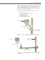
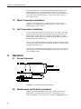
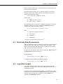
INSTRUCTION MANUAL
Model 107 Temperature Probe
Revision: 11/14
C o p y r i g h t © 1 9 8 3 - 2 0 1 4
C a m p b e l l S c i e n t i f i c , I n c .
Limited Warranty
“Products manufactured by CSI are warranted by CSI to be free from defects in
materials and workmanship under normal use and service for twelve months
from the date of shipment unless otherwise specified in the corresponding
product manual. (Product manuals are available for review online at
www.campbellsci.com.) Products not manufactured by CSI, but that are resold
by CSI, are warranted only to the limits extended by the original manufacturer.
Batteries, fine-wire thermocouples, desiccant, and other consumables have no
warranty. CSI’s obligation under this warranty is limited to repairing or
replacing (at CSI’s option) defective Products, which shall be the sole and
exclusive remedy under this warranty. The Customer assumes all costs of
removing, reinstalling, and shipping defective Products to CSI. CSI will return
such Products by surface carrier prepaid within the continental United States of
America. To all other locations, CSI will return such Products best way CIP
(port of entry) per Incoterms ® 2010. This warranty shall not apply to any
Products which have been subjected to modification, misuse, neglect, improper
service, accidents of nature, or shipping damage. This warranty is in lieu of all
other warranties, expressed or implied. The warranty for installation services
performed by CSI such as programming to customer specifications, electrical
connections to Products manufactured by CSI, and Product specific training, is
part of CSI's product warranty. CSI EXPRESSLY DISCLAIMS AND
EXCLUDES ANY IMPLIED WARRANTIES OF MERCHANTABILITY
OR FITNESS FOR A PARTICULAR PURPOSE. CSI hereby disclaims,
to the fullest extent allowed by applicable law, any and all warranties and
conditions with respect to the Products, whether express, implied or
statutory, other than those expressly provided herein.”
Assistance
Products may not be returned without prior authorization. The following
contact information is for US and international customers residing in countries
served by Campbell Scientific, Inc. directly. Affiliate companies handle
repairs for customers within their territories. Please visit
www.campbellsci.com to determine which Campbell Scientific company serves
your country.
To obtain a Returned Materials Authorization (RMA), contact CAMPBELL
SCIENTIFIC, INC., phone (435) 227-9000. After an application engineer
determines the nature of the problem, an RMA number will be issued. Please
write this number clearly on the outside of the shipping container. Campbell
Scientific’s shipping address is:
CAMPBELL SCIENTIFIC, INC.
RMA#_____
815 West 1800 North
Logan, Utah 84321-1784
For all returns, the customer must fill out a “Statement of Product Cleanliness
and Decontamination” form and comply with the requirements specified in it.
The form is available from our web site at www.campbellsci.com/repair. A
completed form must be either emailed to [email protected] or faxed to
(435) 227-9106. Campbell Scientific is unable to process any returns until we
receive this form. If the form is not received within three days of product
receipt or is incomplete, the product will be returned to the customer at the
customer’s expense. Campbell Scientific reserves the right to refuse service on
products that were exposed to contaminants that may cause health or safety
concerns for our employees.
Precautions
DANGER — MANY HAZARDS ARE ASSOCIATED WITH INSTALLING, USING, MAINTAINING, AND WORKING ON OR AROUND
TRIPODS, TOWERS, AND ANY ATTACHMENTS TO TRIPODS AND TOWERS SUCH AS SENSORS, CROSSARMS, ENCLOSURES,
ANTENNAS, ETC. FAILURE TO PROPERLY AND COMPLETELY ASSEMBLE, INSTALL, OPERATE, USE, AND MAINTAIN TRIPODS,
TOWERS, AND ATTACHMENTS, AND FAILURE TO HEED WARNINGS, INCREASES THE RISK OF DEATH, ACCIDENT, SERIOUS
INJURY, PROPERTY DAMAGE, AND PRODUCT FAILURE. TAKE ALL REASONABLE PRECAUTIONS TO AVOID THESE HAZARDS.
CHECK WITH YOUR ORGANIZATION'S SAFETY COORDINATOR (OR POLICY) FOR PROCEDURES AND REQUIRED PROTECTIVE
EQUIPMENT PRIOR TO PERFORMING ANY WORK.
Use tripods, towers, and attachments to tripods and towers only for purposes for which they are designed. Do not exceed design
limits. Be familiar and comply with all instructions provided in product manuals. Manuals are available at www.campbellsci.com or
by telephoning (435) 227-9000 (USA). You are responsible for conformance with governing codes and regulations, including safety
regulations, and the integrity and location of structures or land to which towers, tripods, and any attachments are attached. Installation
sites should be evaluated and approved by a qualified engineer. If questions or concerns arise regarding installation, use, or
maintenance of tripods, towers, attachments, or electrical connections, consult with a licensed and qualified engineer or electrician.
General
• Prior to performing site or installation work, obtain required approvals and permits. Comply
with all governing structure-height regulations, such as those of the FAA in the USA.
• Use only qualified personnel for installation, use, and maintenance of tripods and towers, and
any attachments to tripods and towers. The use of licensed and qualified contractors is highly
recommended.
• Read all applicable instructions carefully and understand procedures thoroughly before
beginning work.
• Wear a hardhat and eye protection, and take other appropriate safety precautions while
working on or around tripods and towers.
• Do not climb tripods or towers at any time, and prohibit climbing by other persons. Take
reasonable precautions to secure tripod and tower sites from trespassers.
• Use only manufacturer recommended parts, materials, and tools.
Utility and Electrical
• You can be killed or sustain serious bodily injury if the tripod, tower, or attachments you are
installing, constructing, using, or maintaining, or a tool, stake, or anchor, come in contact with
overhead or underground utility lines.
• Maintain a distance of at least one-and-one-half times structure height, 20 feet, or the distance
required by applicable law, whichever is greater, between overhead utility lines and the
structure (tripod, tower, attachments, or tools).
• Prior to performing site or installation work, inform all utility companies and have all
underground utilities marked.
• Comply with all electrical codes. Electrical equipment and related grounding devices should
be installed by a licensed and qualified electrician.
Elevated Work and Weather
• Exercise extreme caution when performing elevated work.
• Use appropriate equipment and safety practices.
• During installation and maintenance, keep tower and tripod sites clear of un-trained or nonessential personnel. Take precautions to prevent elevated tools and objects from dropping.
• Do not perform any work in inclement weather, including wind, rain, snow, lightning, etc.
Maintenance
• Periodically (at least yearly) check for wear and damage, including corrosion, stress cracks,
frayed cables, loose cable clamps, cable tightness, etc. and take necessary corrective actions.
• Periodically (at least yearly) check electrical ground connections.
WHILE EVERY ATTEMPT IS MADE TO EMBODY THE HIGHEST DEGREE OF SAFETY IN ALL CAMPBELL SCIENTIFIC PRODUCTS,
THE CUSTOMER ASSUMES ALL RISK FROM ANY INJURY RESULTING FROM IMPROPER INSTALLATION, USE, OR
MAINTENANCE OF TRIPODS, TOWERS, OR ATTACHMENTS TO TRIPODS AND TOWERS SUCH AS SENSORS, CROSSARMS,
ENCLOSURES, ANTENNAS, ETC.
Table of Contents
PDF viewers: These page numbers refer to the printed version of this document. Use the
PDF reader bookmarks tab for links to specific sections.
1. Introduction ................................................................. 1
2. Cautionary Statements ............................................... 1
3. Initial Inspection ......................................................... 1
4. Quickstart .................................................................... 1
5. Overview ...................................................................... 4
6. Specifications ............................................................. 4
7. Installation ................................................................... 5
7.1
7.2
Wiring to Datalogger ........................................................................... 5
Datalogger Programming ..................................................................... 5
7.2.1 Therm107() Instruction ................................................................. 6
7.3
Air Temperature Installation ................................................................ 6
7.4
Water Temperature Installation............................................................ 8
7.5
Soil Temperature Installation ............................................................... 8
8. Operation ..................................................................... 8
8.1
8.2
8.3
8.4
Sensor Schematic ................................................................................. 8
Measurement and Output Linearization ............................................... 8
Electrically Noisy Environments ......................................................... 9
Long Cable Lengths ............................................................................. 9
9. Troubleshooting and Maintenance ......................... 10
9.1
9.2
9.3
Troubleshooting ................................................................................. 10
Maintenance ....................................................................................... 10
Calibration.......................................................................................... 10
10. Attributions and References .................................... 11
Appendices
A. Importing Short Cut Code Into CRBasic Editor ... A-1
B. Example Programs ................................................. B-1
C. Thermistor Resistance and Temperature ............. C-1
i
Table of Contents
Figures
7-1.
7-2.
8-1.
107 and 41303-5A Radiation Shield on a tripod mast ......................... 7
107 and 41303-5A Radiation Shield on a CM200 Series Crossarm.... 7
107 thermistor probe schematic........................................................... 8
7-1.
C-1.
Wire Color, Function, and Datalogger Connection ............................. 5
107 Thermistor Resistance and Temperature1 ................................. C-1
Tables
ii
Model 107 Temperature Probe
1.
Introduction
The 107 Temperature Probe uses a thermistor to measure temperature in air,
soil, and water. It is compatible with all CRBasic dataloggers except the
CR200(X) and CR9000(X). See Section 6, Specifications, for a list of
compatible CRBasic dataloggers.
For Edlog datalogger support, check the availability of an older manual at
www.campbellsci.com/old-manuals, or contact a Campbell Scientific
application engineer for assistance.
2.
3.
4.
Cautionary Statements
•
READ AND UNDERSTAND the Precautions section at the front of this
manual.
•
Santoprene® rubber, which composes the black outer jacket of the 107
cable, will support combustion in air. It is used because of its resistance to
temperature extremes, moisture, and UV degradation. It is rated as slow
burning when tested according to U.L. 94 H.B. and passes FMVSS302.
However, local fire codes may preclude its use inside buildings.
Initial Inspection
•
Check the packaging and contents of the shipment. If damage occurred
during transport, immediately file a claim with the carrier. Contact
Campbell Scientific to facilitate repair or replacement.
•
Check model information against the shipping documents to ensure the
expected products and the correct lengths of cable are received. Model
numbers are found on each product. On cables and cabled items, the
model number is usually found at the connection end of the cable. Report
any shortages immediately to Campbell Scientific.
Quickstart
Short Cut is an easy way to program your datalogger to measure the 107 probe
and assign datalogger wiring terminals. Use the following procedure to get
started.
1.
Install Short Cut by clicking on the install file icon. Get the install file
from either www.campbellsci.com, the ResourceDVD, or find it in
installations of LoggerNet, PC200W, PC400, or RTDAQ software.
1
Model 107 Temperature Probe
2
2.
The Short Cut installation should place an icon on the desktop of your
computer. To open Short Cut, click on this icon.
3.
When Short Cut opens, select New Program.
4.
Select Datalogger Model and Scan Interval (default of 5 seconds is OK
for most applications). Click Next.
Model 107 Temperature Probe
5.
Under the Available Sensors and Devices list, select the Sensors folder,
then select the Temperature sub-folder. Select 107 Temperature Probe.
Click
to move the selection to the Selected device window. Data
defaults to degree Celsius. This can be changed by clicking the Deg C box
and selecting Deg F, for degrees Fahrenheit, or K for Kelvin.
6.
After selecting the sensor, click at the left of the screen on Wiring
Diagram to see how the sensor is to be wired to the datalogger. The
wiring diagram can be printed out now or after more sensors are added.
7.
Select any other sensors you have, then finish the remaining Short Cut
steps to complete the program. The remaining steps are outlined in Short
Cut Help, which is accessed by clicking on Help | Contents |
Programming Steps.
3
Model 107 Temperature Probe
5.
8.
If LoggerNet, PC400, RTDAQ, or PC200W is running on your PC, and the
PC to datalogger connection is active, you can click Finish in Short Cut
and you will be prompted to send the program just created to the
datalogger.
9.
If the sensor is connected to the datalogger, as shown in the wiring
diagram in step 6, check the output of the sensor in the datalogger support
software data display to make sure it is making reasonable measurements.
Overview
The 107 is a rugged probe that accurately measures air, soil, or water
temperature in a variety of applications. The sensor consists of a thermistor
encapsulated in an epoxy-filled aluminum housing. This design allows the
probe to be buried or submerged in water to 15 m (50 ft) or 21 psi. When
measuring air temperature, a 41303-5A radiation shield is normally used to
mount the 107 and limit solar radiation loading. See Specifications for a
complete list of compatible dataloggers.
6.
Specifications
Features
• Measures air, soil, or water temperature
• Compatible with AM16/32-series multiplexers
• Easy to install or remove
• Durable
• Compatible with the following CRBasic dataloggers: CR6 and
CR800 series, CR1000, CR3000, and CR5000
Sensor Element:
Survival Range:
Measurement Range:
Measurement Specialties 100K6A1iA
thermistor
–50 to 100 °C
–35 to 50 °C
Time Constant in Air:
30 to 60 s in a wind speed of 5 m/s
Maximum Cable Length:
1000 ft
Accuracy1
Worst case:
±0.4 °C (–24 to 48 °C)
±0.9 °C (–35 to 50 °C)
Interchangeability Error:
±0.10 °C (0 to 50 °C)
±0.20 °C at –10 °C
±0.30 °C at –20 °C
±0.40 °C at –30 °C
±0.50 °C at –40 °C
Steinhart-Hart
Equation Error:
4
≤ ±0.01 °C (–35 to 50 °C)
Model 107 Temperature Probe
Probe Weight and Dimensions
Weight with 10 ft cable:
Length:
Diameter:
136 g (5 oz)
10.4 cm (4.1 in)
0.762 cm (0.3 in)
1
Overall probe accuracy is a combination of thermistor interchangeability, bridge-resistor
accuracy, and error of the Steinhart-Hart equation. Interchangeability is the principle component
error. For 0 to 50 °C, the interchangeability error is predominantly offset and can be determined
with a single- point calibration. Offset can be entered in the Therm107() instruction Offset
parameter. Bridge resistors have 0.1% tolerance with a 10 ppm temperature coefficient.
7.
Installation
If you are programming your datalogger with Short Cut, skip Section 7.1,
Wiring to Datalogger, and Section 7.2, Datalogger Programming. Short Cut
does this work for you. See Section 4, Quickstart, for a Short Cut tutorial.
7.1
Wiring to Datalogger
TABLE 7-1. Wire Color, Function, and Datalogger Connection
Wire Color
Wire Function
Datalogger Connection
Terminal
Black
Voltage-excitation input
U configured for voltage
excitation1, EX, VX
(voltage excitation)
Red
Analog-voltage output
U configured for single-ended
analog input1, SE
(single-ended,
analog-voltage input)
Purple
Bridge-resistor lead
AG or
(analog ground)
Clear
EMF shield
AG or
(analog ground)
U channels are automatically configured by the measurement instruction.
1
7.2
Datalogger Programming
Short Cut is the best source for up-to-date datalogger programming code.
Programming code is needed when,
•
•
Creating a program for a new datalogger installation
Adding sensors to an existing datalogger program
If your data acquisition requirements are simple, you can probably create and
maintain a datalogger program exclusively with Short Cut. If your data
acquisition needs are more complex, the files that Short Cut creates are a great
source for programming code to start a new program or add to an existing
custom program.
5
Model 107 Temperature Probe
NOTE
Short Cut cannot edit programs after they are imported and edited
in CRBasic Editor.
A Short Cut tutorial is available in Section 4, Quickstart. If you wish to import
Short Cut code into CRBasic Editor to create or add to a customized program,
follow the procedure in Appendix B.1, Importing Short Cut Code into a
Program Editor. Programming basics are provided in the following section. A
complete program example can be found in Appendix B, Example Programs.
If the 107 probe is to be used with long cable lengths or in electrically noisy
environments, consider employing the measurement programming techniques
outlined in Section 8.3, Electrically Noisy Environments, and Section 8.4, Long
Cable Lengths.
Details of 107 probe measurement and linearization of the thermistor output
are provided in Section 8.2, Measurement and Output Linearization.
7.2.1 Therm107() Instruction
The Therm107() measurement instruction programs CRBasic dataloggers
(CR6- and CR800-series, CR1000, CR3000, and CR5000) to measure the 107
probe. It supplies 2500 mV excitation, makes a half-bridge resistance
measurement, and converts the result to temperature using the Steinhart-Hart
equation. See Section 8.2, Measurement and Output Linearization, for more
information. Therm107() instruction and parameters are as follows:
Therm107(Dest, Reps, SEChan, VxChan, SettlingTime, Integ/Fnotch,
Mult, Offset)
Variations:
•
•
•
•
7.3
Temperature reported as °C — set Mult to 1 and Offset to 0
Temperature reported as °F — set Mult to 1.8 and Offset to 32
Ac mains noise filtering — set Integ/Fnotch to _60Hz or _50Hz (see
Section 8.3, Electrically Noisy Environments)
Compensate for long cable lengths — Set SettlingTime to 20000 (see
Section 8.4, Long Cable Lengths)
Air Temperature Installation
For air temperature measurements, locate probes over an open level area at
least 9 m (EPA) in diameter. The surface should be covered by short grass or
the natural earth surface where grass does not grow. Probes should be located
at a distance of at least four times the height of any nearby obstruction, and at
least 30 m (EPA) from large paved areas. Sensors should be protected from
thermal radiation, and adequately ventilated.
Standard air temperature measurement heights:
•
•
•
1.25 to 2.0 m (WMO)
2.0 m (EPA)
2.0 m and 10.0 m for temperature difference (EPA)
When exposed to sunlight, the 107 should be housed in a 41303-5A or 413035B six-plate solar radiation shield. The white color reflects solar radiation, and
6
Model 107 Temperature Probe
the louvered construction allows air to pass freely through, thereby keeping the
probe at or near ambient temperature. The 41303-5A attaches to a crossarm,
mast, or user-supplied pipe with a 2.5 to 5.3 cm (1.0 to 2.1 inch) outer
diameter. The 41303-5B attaches to a CM500-series pole or a user-supplied
pole with a 5.1 cm (2.4 inch) outer diameter.
Tools required for installing a radiation shield to a tripod or tower include:
•
•
•
•
•
1/2 inch open end wrench
small screw driver provided with datalogger
small Phillips screwdriver
UV resistant cable ties
small pair of diagonal-cutting pliers
41303-5A
107
Tripod Mast
or Tower Leg
FIGURE 7-1. 107 and 41303-5A Radiation Shield on a tripod mast
41303-5A
Tripod Mast
or Tower Leg
107
CM200 Series Crossarm
FIGURE 7-2. 107 and 41303-5A Radiation Shield on a CM200 Series
Crossarm
7
Model 107 Temperature Probe
The 107 is held in the 41303-5A radiation shield by a mounting clamp at the
bottom (FIGURE 7-2). Loosen the mounting clamp screws, and insert the
probe through the clamp. Tighten the screws to secure the sensor and route the
sensor cable to the instrument enclosure. Secure the cable to the tripod or
tower using cable ties.
7.4
Water Temperature Installation
107 probes can be submerged to 15 m (50 ft) or 21 psi. The 107 is not
weighted, so a weighting system should be added, or the probe secured to a
submerged object such as a piling.
7.5
Soil Temperature Installation
The 107 tends to measure the average temperature over its length, so burying
the probe such that the measurement tip is horizontal to the soil surface at the
desired depth is usually preferred. The maximum burial depth for soil that
could become saturated with water is dictated by the maximum water pressure
allowed for the sensor, which is 21 psi.
One or two coils of cable should also be buried in a shallow installation. Burial
of some cable mitigates the effect of solar heating of the above ground cable on
the temperature measurement.
Placement of the cable inside a rugged conduit may be necessary for long cable
runs, especially in locations subject to digging, mowing, traffic, use of power
tools, or lightning strikes.
8.
Operation
8.1
Sensor Schematic
FIGURE 8-1. 107 thermistor probe schematic
8.2
Measurement and Output Linearization
CRBasic instruction Therm107() measures the 107 probe thermistor and
automatically converts the result to temperature. With reference to the
previous FIGURE 8-1, 107 thermistor probe schematic, Therm107() applies a
8
Model 107 Temperature Probe
precise excitation voltage at the Vx line and measures the voltage drop across
the 1 kΩ resistor at the Vs line.
The ratio of measured voltage (Vs) to excitation voltage (Vx) is related to
thermistor resistance (Rs), and the 1 kΩ ohm and 249 kΩ fixed resistors as
described in the following equations:
Vs/Vx = 1000 / (Rs + 249000 Ω + 1000 Ω)
Solving for Rs:
Rs + 250000 Ω = 1000 • (Vx/Vs)
Rs = 1000 • (Vx/Vs) – 250000
The relationship of Rs to temperature is tabulated in Appendix C, Thermistor
Resistance and Temperature, but is calculated by Therm107() using the
Steinhart-Hart equation, described as follows:
Tc = (1 / (A + B • ln (Rs) + C • (ln (Rs))3)) – 273.15
where:
Tc = temperature in degrees Celsius (°C)
A1 = 8.271111E–4
B1 = 2.088020E–4
C1 = 8.059200E–8
1Coefficients
8.3
provided by Measurement SpecialtiesTM.
Electrically Noisy Environments
EMF noise emanating from the ac mains power grid can be a significant source
of measurement error. 60 Hz noise is common in the United States. 50 Hz
noise is common in Europe and other regions. Depending on the datalogger
model, this noise can usually be filtered out.
The following code snips filter 60 Hz noise by placing the _60Hz argument in
the Integ/Fnotch parameter (in bold type).
For CR6 datalogger:
Therm107(T107_C,1,U1,U10,0,_60Hz,1.0,0.0)
For CR800, CR1000, CR3000, and CR5000 dataloggers:
Therm107(T107_C,1,1,Vx1,0,_60Hz,1.0,0.0)
8.4
Long Cable Lengths
Long cable lengths may require longer than normal analog measurement
settling times. Settling times are increased by adding a measurement delay to
the datalogger program.
The 60 Hz and 50 Hz integration options include a 3 ms settling time; longer
settling times can be entered into the Settling Time parameter. The following
code snips increase settling time by 20000 µs by placing 20000 as the
argument in the SettlingTime parameter:
9
Model 107 Temperature Probe
For CR6 datalogger:
Therm107(T107_C,1,U1,U10,20000,_60Hz,1.0,0.0)
For CR800, CR1000, CR3000, and CR5000 dataloggers:
Therm107(T107_C,1,1,1,20000,_60Hz,1.0,0.0)
9.
Troubleshooting and Maintenance
NOTE
9.1
All factory repairs and recalibrations require a returned material
authorization (RMA) and completion of the “Declaration of
Hazardous Material and Decontamination” form. Refer to the
Assistance page at the beginning of this manual for more
information.
Troubleshooting
Symptom: Temperature is reported as NAN, –INF, or incorrect temperature.
Verify wire leads are connected to the terminals specified in the
Therm107() instruction: red to single-ended analog input (SE or U), black
to switched excitation (VX/EX or U), and purple to ground ( ).
Symptom: Incorrect temperature is reported.
Verify the Mult and Offset arguments in Therm107() are correct for the
desired units (Section 7.2, Datalogger Programming). Check the cable for
signs of damage and possible moisture intrusion.
Symptom: Unstable temperature is reported.
Probably a result of electromagnetic interference. Try using the _50Hz or
_60Hz Integ or Fnotch options, and/or increasing the settling time as
described in Section 8.3, Electrically Noisy Environments, and Section 8.4,
Long Cable Lengths. Ensure the clear wire is connected to datalogger
ground, and the datalogger is properly grounded.
9.2
Maintenance
The 107 probe requires minimal maintenance. For air temperature
measurements, check the radiation shield monthly to make sure it is clean and
free from debris. Periodically check cabling for signs of damage and possible
moisture intrusion.
9.3
Calibration
Calibration of the 107 probe is not necessary unless the application requires
removal of the thermistor interchangeability offset described in Section 6,
Specifications.
10
Model 107 Temperature Probe
10. Attributions and References
Santoprene® is a registered trademark of Exxon Mobile Corporation.
EPA installation standard: Quality Assurance Handbook for Air Pollution
Measurement Systems – Volume IV: Meteorological Measurements Version 2.0
WMO standard: WMO No. 8, Seventh edition, 6 Aug 2008 Guide to
Meteorological Instruments and Methods of Observation
11
Model 107 Temperature Probe
12
Appendix A. Importing Short Cut Code
Into CRBasic Editor
This tutorial shows:
•
•
How to import a Short Cut program into a program editor for
additional refinement
How to import a wiring diagram from Short Cut into the comments of
a custom program
Short Cut creates the following files, which can be imported into CRBasic
Editor. Assuming defaults were used when Short Cut was installed, these files
reside in the C:\campbellsci\SCWin folder:
•
•
•
•
•
•
.DEF (wiring and memory usage information)
.CR6 (CR6 datalogger code)
.CR1 (CR1000 datalogger code)
.CR8 (CR800 datalogger code)
.CR3 (CR3000 datalogger code)
.CR5 (CR5000 datalogger code)
Use the following procedure to import Short Cut code and wiring diagram into
CRBasic Editor.
NOTE
1.
Create the Short Cut program following the procedure in Section 4,
Quickstart. Finish the program and exit Short Cut. Make note of the file
name used when saving the Short Cut program.
2.
Open CRBasic Editor.
3.
Click File | Open. Assuming the default paths were used when Short Cut
was installed, navigate to C:\CampbellSci\SCWin folder. The file of
interest has the .CR6, .CR1, .CR8, .CR3, or .CR5 extension. Select the file
and click Open.
4.
Immediately save the file in a folder different from
C:\Campbellsci\SCWin, or save the file with a different file name.
Once the file is edited with CRBasic Editor, Short Cut can no
longer be used to edit the datalogger program. Change the name
of the program file or move it, or Short Cut may overwrite it next
time it is used.
5.
The program can now be edited, saved, and sent to the datalogger.
6.
Import wiring information to the program by opening the associated .DEF
file. Copy and paste the section beginning with heading “-Wiring for
CRXXX–” into the CRBasic program, usually at the head of the file.
After pasting, edit the information such that an apostrophe (') begins each
line. This character instructs the datalogger compiler to ignore the line
when compiling.
A-1
Appendix A. Importing Short Cut Code Into CRBasic Editor
A-2
Appendix B. Example Programs
This following example can be used directly with CR800 series, CR1000,
CR3000, and CR5000 dataloggers.
'Program measures one 107 temperature probe once a second and
'stores the average temperature every 60 minutes.
'Wiring Diagram
'==============
' 107
' Probe
' Lead
' Color
Function
' -----------' Black
Voltage-excitation input
' Red
Analog-voltage output
' Purple
Bridge-resistor ground
' Clear
Shield
CR1000
Terminal
-----VX1/EX1
SE1
Ground Symbol
Ground Symbol
'Declare the variables for the temperature measurement
Public T107_C
'Define a data table for 60 minute averages:
DataTable(Table1,True,-1)
DataInterval(0,60,Min,0)
Average(1,T107_C,IEEE4,0)
EndTable
BeginProg
Scan(1,Sec,1,0)
'Measure the temperature
Therm107(T107_C,1,1,Vx1,0,_60Hz,1.0,0.0)
'Call Data Table
CallTable(Table1)
NextScan
EndProg
The following example can be used directly with CR6 series dataloggers.
'Program measures one 107 temperature probe once a second and
'stores the average temperature every 60 minutes.
'Wiring Diagram
'==============
' 107
' Probe
' Lead
' Color
Function
' -----------' Black
Voltage-excitation input
' Red
Analog-voltage output
' Purple
Bridge-resistor ground
' Clear
Shield
CR6
Terminal
-----U10
U1
Ground Symbol
Ground Symbol
'Declare the variables for the temperature measurement
Public T107_C
'Define a data table for 60 minute averages:
DataTable(Table1,True,-1)
DataInterval(0,60,Min,0)
Average(1,T107_C,IEEE4,0)
EndTable
B-1
Appendix B. Example Programs
BeginProg
Scan(1,Sec,1,0)
'Measure the temperature
Therm107(T107_C,1,U1,U10,0,_60Hz,1.0,0.0)
'Call Data Table
CallTable(Table1)
NextScan
EndProg
B-2
Appendix C. Thermistor Resistance
and Temperature
TABLE C-1. 107 Thermistor Resistance and Temperature1
Actual
Temperature (°C)
100K6A1iA
Thermistor
Resistance (Ω)
CRBasic
Therm107()
Output (°C)
-40
-39
-38
-37
-36
-35
-34
-33
-32
-31
-30
-29
-28
-27
-26
-25
-24
-23
-22
-21
-20
-19
-18
-17
-16
-15
-14
-13
-12
-11
-10
-9
-8
-7
-6
-5
-4
-3
-2
-1
0
1
2
3
4071186
3798837
3546330
3312107
3094743
2892930
2705469
2531260
2369292
2218639
2078448
1947934
1826376
1713112
1607529
1509065
1417202
1331461
1251401
1176615
1106727
1041391
980285
923112
869600
819493
772557
728575
687344
648680
612407
578366
546408
516394
488196
461695
436779
413346
391300
370551
351017
332620
315288
298954
-40.00
-39.00
-38.00
-37.00
-36.00
-35.00
-34.00
-33.00
-32.00
-31.00
-30.00
-29.00
-28.00
-27.00
-26.00
-25.00
-24.00
-23.00
-22.00
-21.00
-20.00
-19.00
-18.00
-17.00
-16.00
-15.00
-14.00
-13.00
-12.00
-11.00
-10.00
-9.00
-8.00
-7.00
-6.00
-5.00
-4.00
-3.00
-2.00
-1.00
0.00
1.00
2.00
3.00
C-1
Appendix C. Thermistor Resistance and Temperature
4
5
6
7
8
9
10
11
12
13
14
15
16
17
18
19
20
21
22
23
24
25
26
27
28
29
30
31
32
33
34
35
36
37
38
39
40
41
42
43
44
45
46
47
48
49
50
51
52
53
54
55
1Data from Measurement SpecialtiesTM
C-2
283555
269034
255335
242408
230206
218684
207801
197518
187799
178610
169921
161700
153921
146558
139586
132983
126727
120799
115179
109850
104795
100000
95449
91129
87027
83131
79430
75913
72569
69390
66367
63491
60755
58150
55670
53309
51060
48917
46875
44929
43073
41303
39615
38005
36467
35000
33599
32262
30984
29763
28596
27481
4.00
5.00
6.00
7.00
8.00
9.00
10.00
11.00
12.00
13.00
14.00
15.00
16.00
17.00
18.00
19.00
20.00
21.00
22.00
23.00
24.00
25.00
26.00
27.00
28.00
29.00
30.00
31.00
32.00
33.00
34.00
35.00
36.00
37.00
38.00
39.00
40.00
41.00
42.00
43.00
44.00
45.00
46.00
47.00
48.00
49.00
50.00
51.00
52.00
53.00
54.00
55.00
Campbell Scientific Companies
Campbell Scientific, Inc. (CSI)
815 West 1800 North
Logan, Utah 84321
UNITED STATES
www.campbellsci.com • [email protected]
Campbell Scientific Centro Caribe S.A. (CSCC)
300 N Cementerio, Edificio Breller
Santo Domingo, Heredia 40305
COSTA RICA
www.campbellsci.cc • [email protected]
Campbell Scientific Africa Pty. Ltd. (CSAf)
PO Box 2450
Somerset West 7129
SOUTH AFRICA
www.csafrica.co.za • [email protected]
Campbell Scientific Ltd. (CSL)
Campbell Park
80 Hathern Road
Shepshed, Loughborough LE12 9GX
UNITED KINGDOM
www.campbellsci.co.uk • [email protected]
Campbell Scientific Australia Pty. Ltd. (CSA)
PO Box 8108
Garbutt Post Shop QLD 4814
AUSTRALIA
www.campbellsci.com.au • [email protected]
Campbell Scientific Ltd. (CSL France)
3 Avenue de la Division Leclerc
92160 ANTONY
FRANCE
www.campbellsci.fr • [email protected]
Campbell Scientific (Beijing) Co., Ltd.
8B16, Floor 8 Tower B, Hanwei Plaza
7 Guanghua Road
Chaoyang, Beijing 100004
P.R. CHINA
www.campbellsci.com • [email protected]
Campbell Scientific Ltd. (CSL Germany)
Fahrenheitstraße 13
28359 Bremen
GERMANY
www.campbellsci.de • [email protected]
Campbell Scientific do Brasil Ltda. (CSB)
Rua Apinagés, nbr. 2018 ─ Perdizes
CEP: 01258-00 ─ São Paulo ─ SP
BRASIL
www.campbellsci.com.br • [email protected]
Campbell Scientific Spain, S. L. (CSL Spain)
Avda. Pompeu Fabra 7-9, local 1
08024 Barcelona
SPAIN
www.campbellsci.es • [email protected]
Campbell Scientific Canada Corp. (CSC)
14532 – 131 Avenue NW
Edmonton AB T5L 4X4
CANADA
www.campbellsci.ca • [email protected]
Please visit www.campbellsci.com to obtain contact information for your local US or international representative.