1
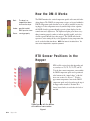
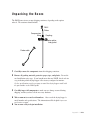
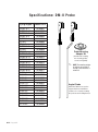
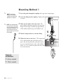
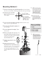
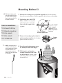
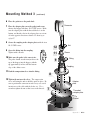
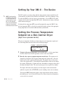
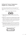
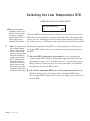
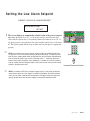
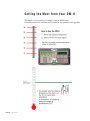
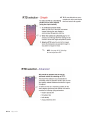
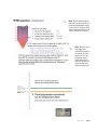
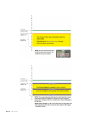
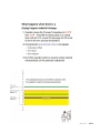
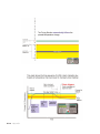
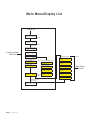
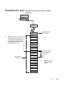
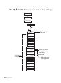
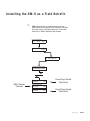
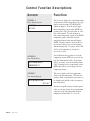
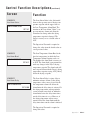
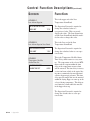
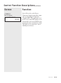
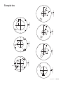
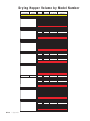
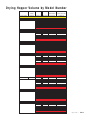
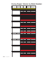
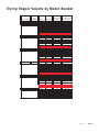
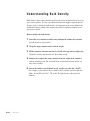
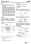
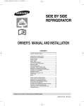
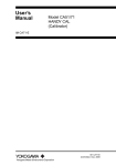
DM-II Drying Monitor
What is the DM-II Drying Monitor?
The DM-II Drying Monitor is a patented instrument that is integrated into your
dehumidifying drying system. The DM-II monitors the drying process as it occurs
within the drying hopper. The DM-II can be programmed to alert the operator if
the drying process deviates from a pre-determined and programmed range of drying parameters established by the operator.
Ty p i c a l A p p l i c a t i o n s
The DM-II is ideal for applications that require strict control of the drying process
to meet product quality specifications. The DM-II can also aid in the prevention of
part rejects through early identification of potential drying problems.
The DM-II will alert the operator, through a passive alarm shown on the control
and on a light tower located on the top of the dryer, that one of these common drying problems may exist.
• A change in the temperature profile within the drying hopper.
• Loss of air flow through the drying hopper.
• A reduction or loss of drying time at the selected and programmed drying
temperature.
Appendix l AA-1
H o w t h e D M - I I Wo r k s
Red -
The dryer has
stopped/shut down
alarm on the dryer
Amber - possible trouble/
DM-II passive alarm
Green - running properly
The DM-II monitors the vertical temperature profile of the material in the
drying hopper. The DM-II's six temperature sensors are located within the
DM-II's temperature probe that has been / or will be installed in your drying hopper. If the temperature moves beyond the high or low setpoints,
the DM-II alerts the operator through a passive alarm displayed on the
control front and a light tower. The light tower lights green when everything is running properly, amber to indicate possible trouble, and red to
alert the operator that the dryer has stopped. The DM-II will alert the
operator if, after starting the dryer, the appropriate drying temperature has
not be reached within four hours. NOTE: Four hours is the default time. The
time can be changed with a supervisor password.
RT D S e n s o r Po s i t i o n s i n t h e
Hopper
RTD's will be referred to in this Appendix and
on your dryer as T1, T2, T3, T4, T5, and T6.
T1 is the lower most temperature sensor within
the DM-II temperature probe and is positioned
at the bottom of the “funnel-shape” of the diffuser cone section. See Figure 1. T6 is the
upper most temperature sensor in the DM-II
temperature probe and is located near the top of
the hopper when installed. Position T6 is
always located in the air void above the bed of
material.
Probe lines up with the bottom
of the diffuser cone section
Figure 1
AA-2 l Appendix
Unpacking the Boxes
The DM-II comes in two or more shipping containers, depending on the options
ordered. The containers should include:
DM-II
Probe
Compression
fitting
Coupling
Adapter plates
and gasket
Probe cable
1 Carefully remove the components from their shipping containers.
2 Remove all packing material, protective paper, tape, and plastic. Do not discard installation notice tags. If you bought more than one DM-II, check each for
a tag indicating which drying hopper it was factory-configured to monitor.
See the specifications on the next page to match the drying hopper model with
the part number on the DM-II probe.
3 Carefully inspect all components to make sure no damage occurred during
shipping, and that you have all the necessary hardware.
4 Take a moment to record serial numbers. Also record the drying hopper’s
5
model number and specifications. The information will be helpful if you ever
need service or parts.
You are now ready to begin installation.
Appendix l AA-3
Specifications: DM-II Probe
Drying Hopper # Conair Part #
CH/RW 10-1
CH/RW 10-1.5
CH/RW 14-2
CH/RW 14-3
CH/RW 14-4
CH 18-4
RW 18-5
CH/RW 18-6
CH 24-8
RW 24-9
CH/RW 24-12
CH/RW 24-15
CH/RW 24-18
CH/RW 33-21
CH/RW 33-28
CH/RW 39-35
CH/RW 39-42
CH/RW 44-58
CH 54-70
CH 54-85
CH 54-99
CH 54-114
CH 54-129
CH 64-158
CH 64-187
CH 64-215
CH 64-248
CH 74-245
CH 74-366
CH 74-487
AA-4 l Appendix
18189901
18189902
18189903
18189904
18189905
18189906
18189907
18189908
18189909
18189910
18189911
18189912
18189913
18189914
18189915
18189916
18189917
18189918
18189919
18189920
18189921
18189922
18189923
18189924
18189925
18189926
18189927
18189928
18189929
18189930
Probe Mounting
Adapter Kit
✐
(Includes half coupling,
two mounting plates,
screws, and gasket)
NOTE: The mounting adapter
kit will only be included if
the DM-II was ordered as a
retrofit kit.
Angled Probe
Allows the DM-II to be used on
hoppers that have insufficient
clearance for correctly mounting
the probe around loading devices.
Installing the DM-II Probe
CAUTION: Hopper surfaces may be hot. Make sure the drying hopper is empty
and has cooled to room temperature before installing the probe assembly. Failure to
do so can lead to serious injury.
The DM-II probe is inserted through a hole in the top of the drying hopper and
secured to a threaded coupling with a compression fitting. Mounting adapter plates
may be necessary.
There are three mounting methods for the probe:
l
Select Mounting Method 1 if you purchased a new Conair drying hopper
equipped with a factory-installed coupling for the probe.
l
Select Mounting Method 2 if you are installing the probe and coupling in a
drying hopper that has enough overhead clearance to insert the probe from the
top of the hopper.
l
Select Mounting Method 3 if you are installing the probe and adapter kit on a
drying hopper that does not have enough overhead clearance to insert the probe
from the top.
Appendix l AA-5
Mounting Method 1
✐
NOTE: The mounting
adapter kit will only be
included if the DM-II was
ordered as a retrofit kit.
1 Insert the probe through the coupling in the top of the drying hopper.
2 Screw the fitting into the coupling. Tighten with
a wrench.
Connector
✐
NOTE: If the angled probe is
used, the bend in the probe
must be oriented to the left
of the probe connector. The
male connector must face
directly away from the center
of the hopper.
3 Make sure the probe is the correct size. The
probe should extend from just above the top of the
hopper into the hopper, with the tip approximately
in-line with the bottom edge of the diffuser cone.
4 Push the compression sleeve into the fitting.
5
4
5 Tighten the nut over the sleeve. The compression
sleeve will crimp the tube to hold the probe in
place. Be sure to position the connector in such a
way as to avoid interference of the cable with the
loader, etc. Use a wrench to tighten the nut so that
it covers the threads.
Sleeve
2
Coupling
3
Tools for
Installation:
❒ 3/4-in. wrench
❒ 7/8-in. wrench
AA-6 l Appendix
Mounting Method 2
✐
NOTE: The mounting adapter
kit will only be included if the
DM-II was ordered as a retrofit kit. Remove the mounting
adapter plates from the probe
assembly, you will not need
them. You will need the gasket.
1 Reference the drawings at the end of this Appendix and select the drawing
that reflects your installation. Drill the appropriate hole in the top of the hopper.
2 Drill and tap four 10-32 UNF
1/
2 in. (12.7 mm)
diameter center hole
holes to match the hole pattern
in the coupling.
✒
Four 10-32 UNF
holes evenly spaced
around a 11/2 in.
(38.1 mm) circle
TIP: Stretch cloth or plastic
across the inside of the hopper to
catch metal shavings from the
hole you will drill in the top of the
hopper.
3 Secure the gasket and coupling to the hopper with the four 10-32 screws.
Remove any excess gasket with a knife.
Tools for Installation:
❒ Drill and 10-32 tap
❒ Knife
Connector ❒ Flathead screwdriver
❒ 3/4-in. wrench
❒ 7/8-in. wrench
4 Insert the probe through the coupling in the
top of the hopper.
5 Screw the fitting into the coupling. Tighten
with a wrench.
6 Make sure the probe is the correct size. The
✐
probe should extend from just above the top of
the hopper into the hopper, with the tip approximately in-line with the bottom
edge of the diffuser cone.
7 Push the compression sleeve into
8
7
6
the fitting.
5
8 Tighten the nut over the sleeve.
The compression sleeve will crimp the tube to
hold the probe in place. Be sure to position the
connector in such a way as to avoid interference of the cable with the loader, etc. Use a
wrench to tighten the nut so that it covers the
threads.
Nut
Sleeve
NOTE: If the angled probe is
used, the bend in the probe must
be oriented to the left of the
probe connector. The male connector must face directly away
from the center of the hopper.
Fitting
Coupling
3
Gasket
Appendix l AA-7
Mounting Method 3
✒
TIP: Stretch cloth or plastic
across the inside of the hopper to catch metal shavings
from the hole you will drill in
the top of the hopper.
Tools for Installation:
1 Reference the drawings at the end of this Appendix and select the drawing
that reflects your installation. Drill the appropriate hole in the top of the hopper.
2 Drill and tap three 10-32 UNF
45°
holes to match the screw pattern
in the adapter plates and gasket.
You can use the template in the
appendix.
❒ Drill and 10-32 tap
❒ Flathead screwdriver
2 in. (50.8 mm)
diameter probe hole
❒ 3/4-in. wrench
❒ 7/8-in. wrench
❒ 2-in. hole saw
3 Remove the two adapter plates from the
probe mounting assembly. Set the adapter
plates aside for use in Step 7.
Adapter
plates
✐
NOTE: If the angled probe is
used, the bend in the probe
must be oriented to the left of
the probe connector. The
male connector must face
directly away from the center
of the hopper.
4 Insert the probe and mounting assembly through the door of the hopper.
5 Pull the probe and mounting
assembly through the hole in the
top of the hopper. Fold the gasket
around the probe so that it will fit
through the hole.
5
4
AA-8 l Appendix
Three 10-32 UNF
holes spaced
around a 23/4 in.
(69.9 mm) diameter circle
Mounting Method 3
(continued)
6 Place the gasket over the probe hole.
Connector
7 Place the adapter plates over the gasket and secure
them to the hopper with three 10-32 UNF screws. Make
sure the adapter plate with the threaded holes is on the
bottom, and that the slots in the adapter plates are oriented in the opposite direction as shown. See drawing to
right, #7.
8 Secure the coupling to the adapter plates with the four
10-32 UNF screws.
12
Nut
9 Screw the fitting into the coupling.
11
Tighten with a wrench.
10 Make sure the probe is the correct size.
10
9
The probe should extend from just above the
top of the hopper into the hopper, with the
tip approximately in-line with the bottom
edge of the diffuser cone.
Sleeve
Fitting
Coupling
11 Push the compression sleeve into the fitting.
8
12 Tighten the nut over the sleeve. The compression
sleeve will crimp the tube to hold the probe in place. Be
sure to position the connector in such a way as to avoid
interference of the cable with the loader, etc. Use a
wrench to tighten the nut so that it covers the threads.
Adapter
plate
7
Threaded
adapter plate
Gasket
6
Hopper
Appendix l AA-9
S e t t i n g U p Yo u r D M - I I - T h e B a s i c s
✐
NOTE: To understand the
navigation of your control,
see the Control flow diagrams beginning on page
AA-22 of this appendix.
There are also control flow
diagrams in the operation
section of your dryer manual.
The DC2 control on your dryer ships with the drying monitor software installed, but all
of the functions are turned off by default to avoid nuisance errors due to improper set up.
To enable the DM-II: set the dryer process air temperature, select an RTD for the alarm
setpoint, and select the low temperature RTD sensor. (Instructions for setting each begin
on the bottom of this page).
Selecting the low temperature RTD sensor will automatically engage the DM-II. Once
the low temperature RTD is selected, the control will alert the operator if the appropriate
drying temperature is not reached within four hours (default time).
S e t t i n g t h e P r o c e s s Te m p e r a t u r e
Setpoint on a Non-Central Dryer
(dryer has a process heater)
The process temperature default screen shows the process air temperature setpoint and
the actual temperature measured at the inlet to the drying hopper.
SCREEN 3 (DEFAULT SCREEN)
PROCESS TEMPERATURE
ACT 325°F
SET 325°F
1 Navigate to the process temperature screen on the dryer. See the control function flow charts located in the Operations section of the dryer manual.
2 Enter the dryer process setpoint temperature on the dryer. The setpoint can be
changed by pressing the Select Category button under the setpoint value. Once the
button is pressed, the setpoint will begin to flash. The numeric keys can be used to
enter a new setpoint or the +/- (Increment/ Decrement) buttons can be used to change
the setpoint. Holding the +/- buttons will cause the number to ramp up or down faster
the longer the button is held. The enter key must pressed to accept the new number.
The display will return to the default screen from anyplace in the menu structure
(with the exception of the AUTOTUNE screens) if nothing is done after ten minutes.
Pressing the MENU button from anyplace in the menu structure will also return to
the default screen. See the Control Functions Flow Charts located in the Operations
section of the dryer manual.
AA-10 l Appendix
S e t t i n g t h e P r o c e s s Te m p e r a t u r e
Setpoint on a Central Dryer
If you are using a central dryer, you will need to set the process temperature on the
Hopper Temperature Controller (HTC) connected to your drying hopper. See the
Control Functions Flow Charts located in the Operations section of your HTC manual
UGD031.
SCREEN 4 (PROCESS TEMPERATURE SCREEN)
Actual
Setpoint
250
250
1 Navigate to the process temperature on the Hopper Temperature Controller
(HTC). See the control function flow charts located in the Operations section of
the HTC manual.
2 Enter the process setpoint temperature on the Hopper Temperature Controller
(HTC). The process temperature is a setpoint and the actual temperature measured
at the inlet to the drying hopper. The +/- buttons can be used to change the setpoint.
Holding the +/- buttons will cause the number to ramp up or down faster the longer
the button is held. The display will return to the default screen from any place in
the menu structure if nothing is done for ten minutes.
3 Enter the same process temperature setpoint on the dryer control so that the
control knows the target temperature. Once the process temperature is set at the
HTC, you will need to enter this same temperature setpoint in the drying monitor
control so that the control knows the target temperature. This is set on screen “M”,
see the drying monitor control function flow charts and descriptions later in this
appendix.
SCREEN M (DM-II SETPOINT SCREEN)
DM PROCESS SETPOINT
SET 225°F
Appendix l AA-11
S e l e c t i n g t h e L o w Te m p e r a t u r e RT D
SCREEN B (DM-II LOW ALARM SELECT)
DM LOW ALARM SELECT
✒ TIP: Conair recommends
✐
T4
EDIT
controlling at an RTD in the
middle of the material zone.
This is the DM-II low alarm select screen. On this screen, you will need to select an
For example a full hopper
RTD
to measure the temperature for your low temperature alarm. The default for this
probably around RTD 3 or 4 screen
is set to off. Some hoppers use level sensors to adjust material level in the hophalf-full hopper may be
around the RTD 2 position.
per. If that is the case, you will want to make sure the sensor selected is in the material.
NOTE: If you choose an RTD Observing the temperatures of the RTD's at a steady operating state will help you to
that is too high in hopper,
decide which RTD would be best to use to measure the setting for your low temperathere is a chance that you
ture RTD.
will get a nuisance alarm
when new "cold" material is
loaded into the hopper. To
1 Observe the RTD readings on the dryer control. At a steady operating state
avoid the nuisance alarms
scroll through the RTD readings to understand the temperature profile inside your
you can: adjust the alarm
band (open up the tolerdrying hopper. See page AA-23 “View/Monitor Screens”, the flow chart located on
ance); move the alarm setthat page will help you navigate to the area of the control where you can monitor
point or increase the temthe temperature at each of the RTD locations.
perature offset. You could
also choose a different RTD
located lower in the hopper. 2 Select the Low temperature RTD to use as a low temperature alarm. Press the
"Edit" key and the left side of the display will cycle through the RTD choices.
Once the desired RTD is shown on the left side of the display, press the enter key to
select the RTD.
AA-12 l Appendix
Setting the Low Alarm Setpoint
SCREEN C (DM-II LOW ALARM SETPOINT)
DM LO ALARM SETPOINT
SET 150°F
Menu
1 This screen displays an automatically calculated value of the process temperature minus the offset screen “D”, see the drying monitor control function flow
charts and descriptions later in this manual, minus ½ the band on screen “E”, see
the drying monitor control function flow charts and descriptions later in this manual. This alarm setpoint will move up or down based on your process setpoint temperature.
Select
Category
2
3
4
5
6
Regen. Blower
Regen. Heater
7
8
Clear
0
Auto Start
Dewpoint Control
Set-Back Temp.
Adjust Setpoint
Acknowledge
Alarm
9
Stop
Start
Enter
100
1
2
3
4
5
6
Clear
NOTE: You can choose to accept this value or change it (within the established band limits,
see page AA-27 later in this manual) based on your processing needs. To change the value,
push the select category button under the displayed value so that it begins flashing/blinking,
then use either the numeric keys to enter a new value or the +/- (Increment/ Decrement)
buttons can be used to change the value. Holding the +/- buttons will cause the number to
ramp up or down faster the longer the button is held. Once the new value you have selected
appears in the display push enter.
Process Blower
Process Heater
Next
1
7
✐
Prev
Scroll List
8
0
9
Enter
Numeric Keypad
Adjust Setpoint
Increment/Decrement Buttons
✐
NOTE: If you choose an RTD that is too high in hopper, there is a chance that you will get a
nuisance alarm when new "cold" material is loaded into the hopper. To avoid the nuisance
alarm you can: choose a different RTD located lower in the hopper; adjust the alarm band
(open up the tolerance); move the alarm setpoint or increase the temperature offset.
Appendix l AA-13
G e t t i n g t h e M o s t f r o m Yo u r D M - I I
This simple overview provides an example of how the DM-II works.
Detailed instructions for installation and operation are also contained in this appendix.
AA-14 l Appendix
Appendix l AA-15
✒
TIP: For more information on screen
navigation refer to the control function
flow charts located in this appendix.
✐
NOTE: See page AA-12 “Selecting
the low temperature RTD”
AA-16 l Appendix
✐
NOTE: You will need to know the
bulk density of your material to calculate your drying hopper volume
in cubic feet (ft3). See page AA-40,
"Understanding Bulk Density" and
"How to Calculate Bulk Density".
✐
NOTE: Nuisance alarms
may trigger if the
selected RTD position is
too close to the alarm
set point. In this case,
the operator would
either simply select a
lower RTD or adjust the
alarm set point lower
within the alarm band.
Appendix l AA-17
AA-18 l Appendix
Appendix l AA-19
AA-20 l Appendix
DM-II Series Control Functions
Drying monitor functions are values that you can set or monitor in the Screen Title
and Status Display windows. Press the Menu button then select the category buttons, then the Scroll List ▲ or ▼ buttons (Next/Previous) until the function you
want to set or monitor appears in the Screen Title window.
Control Function Flow Charts
Menu
Select
Category
The charts beginning on page AA-22 provide a quick summary of the control functions. For an explanation of each control function, see “Control Function
Descriptions” (page AA-26).
Prev
Process Blower
Regen. Blower
Scroll List
Process Heater
Regen. Heater
Auto Start
Dewpoint Control
Next
1
2
3
4
5
6
7
8
9
Clear
0
Set-Back Temp.
Adjust Setpoint
Acknowledge
Alarm
Start
Stop
Enter
100
Menu
To access parameters, push the Menu button until “Dryer Main Menu” screen is
displayed. Use the Select Category buttons to access “Dryer Other Status,” “Set
up Process Other,” “Dryer Setup Alarm,” and “Dryer Setup Options” screens.
Use the Next/Previous buttons to scroll through the parameters in each list.
Menu
Menu Button
Select
Category
To change a value, push the Select Category button under the value to be changed
until it blinks, set to desired value, then push enter.
Prev
P
Scroll List
P
Next
2
1 Category
3
Select
Buttons
4
7
Clear
5
8
0
6
Adjust Setpoint
Prev
9
Start
Scroll
Enter List
Next
100
Next/Previous Buttons
Appendix l AA-21
Stop
Main Menu/Display List
POWER ON
CONAIR
CV00.06.2
CP100
DV00.09.8
3 SEC DELAY
MONDAY
7/22/2003
07:59 AM
3 SEC DELAY
STD DRYER
PROCESS TEMPERATURE
Act 140˚F
Set 140˚F
From Dryer Control
Flow Chart
REGENERATION TEMP
ACT 350˚F
SET 350˚F
RETURN AIR TEMP
ACT 120˚F
SET 120˚F
MDC HOPPER LOADER
MACHINE LOADER
LOAD TIME 10 SEC
DRYING MONITOR
PROCESS DEWPOINT
ACT -47˚F
SET -40˚F
PRESS MENU KEY
AT ANY TIME
DRYER MAIN MENU
STAT SETUP DIAG
AA-22 l Appendix
A
MACHINE LOADER
LOAD TIME 10 SEC
DM T5
ACT 155 F
A
HOPPER LDR VIRGIN
LOAD TIME 20 SEC
DM T4
ACT 158 F
A
HOPPER LDR REGRIND
LOAD TIME 20 SEC
DM T3
ACT 160 F
A
HOPPER LOADER
LAYERING
ON
DM T2
ACT 163 F
A
DM T1
ACT 165 F
A
MDC HOPPER LOADER AND RATIO
HOPPER LOADER
LOAD TIME 10 SEC
Screen
DM T6 TOP
ACT 150 F
Reference
DM-II Control
Functions
Vi e w / M o n i t o r O n l y
(Changes can not be made on these
screens.)
DRYER MAIN MENU
STAT SETUP DIAG
DRYER STATUS
PROC REGEN
OTHER
DRYER OTHER
STATUS SCREENS
From Dryer Control
Flow Chart
PANEL INSIDE TEMP
ACT 100˚F
✐
Screen References
A
DM T6 TOP
ACT 150 F
NOTE: Due to tolerances of RTD’s it would
not be uncommon to see a probe with a
temperature that is higher located further
up in the hopper. For example, T4 with an
actual temperature of 164°F and T3 with
an actual temperature of 159°F.
DM T5
ACT 155 F
A
DM T4
ACT 158 F
A
DM T3
A
ACT 160 F
DM T2
A
ACT 163 F
DM T1 BOTTOM
ACT 165 F
A
DM PROCESS SETPOINT
M
SET 225 F
DM-II Control
Functions
DM LO ALARM SELECT
TEMPERATURE T4
B
DM LO ALARM SETPOINT
C
SET 150 F
DM LO ALARM OFFSET
SET 10 F D
DM LO ALARM BAND
E
SET 40 F
DM LO ALARM DELAY
F
SET 5 MIN
Screen only present
if configured for a
central dryer.
Operator
Mode
✐
NOTE: All other screens
require the supervisor
password.
DM LO ALARM SETPOINT
HIGH LIMIT
170 F G
DM LO ALARM SETPOINT
LOW LIMIT
130 F
DM TEMP NOT MET
ALARM TIME SET 4 HRS
H
I
Appendix l AA-23
Set up Screen
(Changes can be made to these settings.)
DRYER MAIN MENU
STAT SETUP
DIAG
PRO ALRM DISP OTHER
SETUP PROCESS
PROC REGEN
OTHER
SETUP PROCESS
OTHER SCREENS
From Dryer Control
Flow Chart
SUNDAY STOP TIME
OFF
8:00 PM
DM T6 TOP
ACT 150 F
Screen References
A
DM T5
ACT 155 F
A
DM T4
ACT 158 F
A
DM T3
A
ACT 160 F
DM T2
A
ACT 163 F
DM T1 BOTTOM
ACT 165 F
A
DM PROCESS SETPOINT
M
SET 225 F
DM LO ALARM SELECT
TEMPERATURE T4
DM LO ALARM SETPOINT
DM-II Control
Functions
SET 150 F
B
C
DM LO ALARM BAND
E
SET 40 F
DM LO ALARM DELAY
F
SET 5 MIN
DM LO ALARM SETPOINT
170 F G
DM LO ALARM SETPOINT
LOW LIMIT
130 F
DM TEMP NOT MET
ALARM TIME SET 4 HRS
AA-24 l Appendix
Operator Mode
✐
DM LO ALARM OFFSET
SET 10 F D
HIGH LIMIT
(Screen only present
if configured for a
central dryer.)
H
I
NOTE: All other screens
require the supervisor
password.
Installing the DM-II as a Field Retrofit.
✐
NOTE: Installing the DM-II as a retrofit requires the service level
password to set up the appropriate screens. Refer to the main portion
of the dryer manual to access the password screen. Please contact
Conair Service 1-800-458-1960 for the proper password.
DRYER MAIN MENU
STAT
SETUP
DIAG
DRYER SETUP
OTHER
DRYER SETUP OTHER
OPT INSP COM PW
DRYER SETUP OPTIONS
INFORMATION SCREENS
DEWPOINT CONTROL
INSTALLED
EDIT
DM-II Control
Function
DRYING MONITOR
INSTALLED
EDIT
PHASE ROTATION
INSTALLED
EDIT
From Dryer Control
Flow Chart
From Dryer Control
Flow Chart
Appendix l AA-25
Control Function Descriptions
Screen
Function
SCREEN A
Dryer Status Screens
The A screens display the actual temperature
of the material in the drying hopper at a particular vertical position (T1 through T6)
within the hopper. T6 is the top or upper
most temperature sensor in the DM-II temperature probe. T6 is located in the air void
above the material. T1 is the bottom or
lower most temperature sensor in the DM-II
temperature probe and will be located
toward the bottom of the material hopper.
NOTE: Changes must be made on the setup screens, status screens are for viewing
and monitoring only. See pages AA-23 and
AA-24 of this appendix for the path to
access the screens.
DM T6 TOP
ACT 150°F
Screen B allows the operator to select the
temperature sensor (RTD) to be used to initiate the alarm function. The "Low Alarm
Select" is factory set to the default position
"Off." You must select a temperature sensor
(RTD) that will be used to trigger the low
temperature alarm.
SCREEN B
Low Alarm Select
DM LO ALARM SELECT
TEMPERATURE T4
SCREEN C
Low Alarm Setpoint
DM LO ALARM SETPOINT
SET 150°F
This screen displays the low temperature
alarm set-point temperature. The low temperature alarm set-point has been factory set
to default to the middle of the low temperature alarm band.
You may accept the factory default setpoint
value or you may change it to a temperature
setpoint of your choosing within the low
temperature alarm band. See screen E
AA-26 l Appendix
C o n t r o l F u n c t i o n D e s c r i p t i o n s (continued)
Screen
Function
SCREEN D
Low Alarm Offset
The Low Alarm Offset is the differential
between the operator entered drying temperature setpoint and the upper value of
the Low Temperature Alarm Band. The
function of the Low Alarm "Offset" is to
prevent nuisance alarms and allow the
alarm band to change when the drying
temperature setpoint is changed. The
Offset is factory set to a default value of
10°F.
DM LO ALARM OFFSET
SET 10 F
The Supervisor Password is required to
change the value from the default value to
a user-preferred value.
SCREEN E
Low Alarm Band
DM LO ALARM BAND
SET 40 F
SCREEN F
Low Alarm Delay
DM LO ALARM DELAY
SET 5 MIN
The Low Temperature Alarm Band is the
band of temperatures in which the Low
Temperature Alarm Setpoint can be set.
The width of the alarm band is factory set
at 40°F. The alarm band is programmed to
track any changes in the Dryer's drying
temperature setpoint. The alarm band will
move up and down with the Dryer's drying
temperature setpoint, staying 10°F [Offset]
below the drying set-point.
The Low Alarm Delay is a time delay to
minimize nuisance alarms. If the drying
temperature at the sensor selected for the
low temperature alarm falls below the
alarm limits the delay timer is activated. If
the drying temperature at that particular
sensor location comes back to within the
alarm limits before the delay timer times
out the delay timer is re-set. However, if
the drying temperature at that sensor
remains below the alarm limits until the
delay timer times out the alarm is initiated.
The Supervisor Password is required to
change this value.
Appendix l AA-27
C o n t r o l F u n c t i o n D e s c r i p t i o n s (continued)
Screen
Function
SCREEN G
Low Alarm Setpoint
This is the upper end of the Low
Temperature Alarm Band.
DM LO ALARM SETPOINT
HIGH LIMIT
170 F
SCREEN H
Low Alarm Setpoint Low Limit
DM LO ALARM SETPOINT
LOW LIMIT
130 F
SCREEN I
Temperature Not Met
Alarm Time Set
DM TEMP NOT MET
ALARM TIME SET
4 HRS
The Supervisor Password is required to
change the calculated value to a
user-preferred value. This screen only
displays the value. The Low Alarm offset
and the Low Alarm Band should be modified in order to change this value.
This is the Low end of the Low
Temperature Alarm Band.
The Supervisor Password is required to
change the calculated value to a user-preferred value.
This is the Temperature Not Met Alarm
Time Delay, which occurs on every startup. The temperature of the selected RTD
must reach the setpoint within the time
delay or the temperature not met alarm
will be activated. The time delay is factory
set for four hours, which is the typical drying time recommended for most moisture
sensitive hygroscopic polymers. This time
delay provides ample time for the material
within the drying hopper to come up to the
selected drying temperature. This helps to
avoid nuisance alarms while the material
in the hopper heats up.
The Supervisor Password is required to
change the default value to a user-preferred value.
AA-28
l Appendix
C o n t r o l F u n c t i o n D e s c r i p t i o n s (continued)
Screen
Function
SCREEN M
Process Setpoint
Screen M is used to set the Process
Temperature Setpoint to match the temperature set on the Hopper Temperature
Controller (HTC). The temperature set on
the DC screen on the HTC and this screen
must match in order for the DM-II to function properly and to avoid nuisance alarms.
This applies to all central dryers. (dryers
without process heaters.)
DM PROCESS SETPOINT
SET 225 F
Appendix l AA-29
Maintenance Checklist
The DM-II requires little maintenance. We recommend the following maintenance schedule and tasks.
• Whenever you change hoppers
❒ Verify or change setpoint entries on the control.
Verify that the temperature settings are correct for the application and
material in this hopper.
• Whenever you change materials
❒ Change the setpoint entries on the control.
Verify that the temperature settings are correct for the new material.
❒ Inspect the probe and mounting assembly.
If the probe is damaged, replace it. If vibration has loosened the probe
mounting hardware, tighten it.
• M o n t h l y, o r a s o f t e n a s n e e d e d
❒ Inspect cables and cords for damage or wear.
Replace any cable or power cord that is worn.
❒ Inspect cable connections.
Check for damage or loose connections. Tighten the connections or
replace the damaged connectors.
AA-30
l Appendix
Tr o u b l e s h o o t i n g
Alarms
Red -
All DM-II alarms are passive and will not cause the dryer to
shutdown.
The amber light on the stack will be on.
The dryer has
stopped/shut down
alarm on the dryer
Amber - possible trouble/
DM-II passive alarm
Green - running properly
1 Press the Acknowledge Alarm button once to display the alarm message.
Pressing the Acknowledge Alarm button once also changes the alarm LED from
blinking to solid.
Menu
Select
Category
Prev
Process Blower
Regen. Blower
Auto Start
Scroll List
Process Heater
Regen. Heater
Dewpoint Control
Next
1
2
3
4
5
6
7
8
9
Clear
0
✐
NOTE: Pushing the
Acknowledge Alarm
button when there is
no active alarm will
take the user directly
to the Alarm History
list.
Set-Back Temp.
Adjust Setpoint
Acknowledge
Alarm
Start
Stop
Enter
100
2 Find the error message in the diagnostics table of this troubleshooting section.
Acknowledge
Alarm LED and
Button
3 Note that pressing the Acknowledge Alarm button a second time will clear
✐
the alarm.
NOTE: If the condition still exists, or if a subsequent alarm has occurred as a result of the original alarm, the alarm will become active again.
Appendix l AA-31
Pa s s i v e A l a r m s
If the amber Acknowledge Alarm LED is blinking, the alarm is a passive alarm.
The dryer continues to operate, but this problem could prevent correct drying of
your material. Note that once the Acknowledge Alarm button is pressed once, the
blinking amber LED becomes solid.
Problem
Drying Monitor
Temperature Not Met
(DM Temp Not Met) - Upon
start-up or a change in setpoint, if the temperature at the
RTD selected in Screen B
does not reach or exceed the
Low Temperature Alarm
Setpoint in Screen C in the
time value in the Drying
Monitor Not Met Screen I,
(Default 4 hours) this alarm
will occur.
Possible cause
Solution
Selected the wrong RTD for the Low
Alarm Select. It may be in the air and
not in the material.
Reselect the RTD. See “Selecting the
Low Temperature RTD,” in this appendix.
On central dryers with HTC, the process
setpoint of the HTC control and drying
setpoint of DM-II may not be the same.
Determine which setpoint is incorrect
and adjust as needed. See “Setting the
Process Temperature on a Central
Dryer,” in this appendix
Material level in hopper is below the
selected Low Temperature Alarm RTD.
Check your material supply system for
loader problems, material availability,
etc.
Process air is not at the proper drying
temperature.
On Central dryers with HTC, ensure the
HTC control has been turned on. Check
for process deviation or loop break
alarms on the dryer or HTC control, and
take the necessary steps to correct these
alarms.
Poor airflow to the hopper.
Clean or replace process filter, dust collector, etc. in the process airstream.
Verify the blower is operating properly,
including correct rotation.
Straighten crimps or remove any objects
that may restrict airflow through hoses
and tubes.
Connect any loose hoses. Replace any
damaged hoses.
AA-32
l Appendix
Pa s s i v e A l a r m s
(continued)
Problem
Possible cause
Solution
Drying Monitor Low
Temperature Alarm
(DM Low Temp) - Once the
temperature at the RTD selected in Screen B has reached the
Low Temperature Alarm
Setpoint in Screen C, the
alarm will become active if
the temperature drops below
the Low Temperature Setpoint
for a length of time longer
than the delay time in Screen
F.
Material throughput too high.
Ensure the material usage is within the
rated capacity of the dryer and hopper in
use.
Material level in the hopper is below the
selected Low Temperature Alarm RTD.
Check your material supply system for
loader problems, material availability,
etc.
Process air is not at the proper drying
temperature.
On central dryers with HTC, ensure the
HTC control has been turned on. Check
for process deviation or loop break
alarms on the dryer or HTC control.
Take whatever steps are necessary to
achieve the correct drying temperature.
On central dryers with HTC, the process
setpoint of the HTC control and drying
setpoint of DM-II may not be the same.
Determine which setpoint is incorrect
and adjust as needed.
Poor airflow to the hopper.
Clean or replace process filter, dust collector, etc. in the process airstream.
Verify the blower is operating properly,
including correct rotation.
Straighten crimps or remove any objects
that may restrict airflow through hoses
and tubes.
Connect any loose hoses. Replace any
damaged hoses.
Appendix l AA-33
Pa s s i v e A l a r m s
AA-34
Problem
Possible cause
Solution
Drying Monitor RTD
Integrity Alarm - This alarm
indicates that one or more of
the RTD sensors within the
Drying Monitor probe have
failed. The drying monitor will
continue to function as long as
the RTD that has failed is not
the one selected for the Low
Alarm or High Alarm RTD, but
the alarm will be present until
the cause of the alarm has been
corrected.
The cable that runs between the Drying
Monitor control and Drying Monitor
probe is loose or damaged.
Verify the cable connections are secure.
Repair or replace the damaged cable or
connectors.
The cable extending from the dryer control is damaged, or the wire connections
from this cable to the analog option
board are loose or broken.
Repair or replace the damaged cable or
connectors, or tighten the wire connections at the analog option board.
Damaged connector on the Drying
Monitor probe.
Repair or replace the damaged connector.
Defective RTD sensor in Drying
Monitor probe.
Replace the probe.
l Appendix
DOOR
24 IN. HOPPER LID
8.00
45.0˚
DOOR
10 IN. HOPPER LID
4.688
DOOR
33 IN. HOPPER LID
9.625
30.0˚
DOOR
14 IN. HOPPER LID
4.75
DOOR
39 IN. HOPPER LID
10.625
30.0˚
DOOR
18 IN. HOPPER LID
8.00
DOOR
44 IN. HOPPER LID
11.50
30.0˚
Te m p l a t e s
Appendix l AA-35
D r y i n g H o p p e r Vo l u m e b y M o d e l N u m b e r
Drying Hopper
Hopper
Diameter
CH/RW 10-1
10
CH/RW 10-1.5
CH/RW 14-2
CH/RW 14-3
CH/RW 14-4
CH18-4
RW 18-5
CH/RW 18-6
AA-36
l Appendix
10
14
14
14
18
18
18
Volume (ft.³) RTD Position
RTD Distance
from the top
Volume up to RTD
position (ft.³)
1
5
8.38
0.85
1
4
12.88
0.65
1
3
17.38
0.45
1
2
21.88
0.28
1
1
26.612
0.09
1.5
5
8.88
1.37
1.5
4
16.13
1.04
1.5
3
23.38
0.72
1.5
2
30.63
0.46
1.5
1
37.88
0.15
2
5
8.75221183
1.62
2
4
13.75221183
1.18
2
3
18.75221183
0.78
2
2
23.75221183
0.35
2
1
28.75221183
0.14
3
5
9.25
2.87
3
4
17.25
2.17
3
3
25.25
1.47
3
2
33.25
0.80
3
1
41.25
0.16
4
5
8.87
3.62
4
4
19.12
2.72
4
3
29.37
1.82
4
2
39.62
0.95
4
1
49.87
0.14
4
5
12.725
3.19
4
4
18.225
2.38
4
3
23.725
1.64
4
2
29.225
0.84
4
1
34.725
0.25
5
5
10.41
4.36
5
4
18.66
3.17
5
3
26.91
1.97
5
2
35.16
0.85
5
1
43.41
0.25
6
5
10.12
5.87
6
4
20.66
4.39
6
3
30.91
2.92
6
2
41.16
1.52
6
1
51.41
0.25
D r y i n g H o p p e r Vo l u m e b y M o d e l N u m b e r
Drying Hopper
Hopper
Diameter
CH 24-8
24
RW 24-9
CH/RW 24-12
CH/RW 24-15
CH/RW 24-18
CH/RW 33-21
CH/RW 33-28
CH/RW 39-35
24
24
24
24
33
33
39
Volume (ft.³) RTD Position
RTD Distance
from the top
Volume up to RTD
position (ft.³)
8
5
13.23
7.38
8
4
20.73
5.50
8
3
28.23
3.56
8
2
35.73
1.58
8
1
43.23
0.39
9
5
10.79
8.73
9
4
19.54
6.48
9
3
28.35
4.22
9
2
37.04
2.09
9
1
45.79
0.47
12
5
53.33
10.89
12
4
42.58
8.14
12
3
31.83
5.39
12
2
21.08
2.72
12
1
10.33
0.52
15
5
11.13
12.60
15
4
24.63
9.14
15
3
38.13
5.69
15
2
51.63
2.32
15
1
65.13
0.57
18
5
10.88
15.56
18
4
27.38
11.35
18
3
43.88
7.15
18
2
60.38
2.94
18
1
76.88
0.55
21
5
18.30
19.66
21
4
29.80
13.96
21
3
41.30
8.27
21
2
52.80
2.95
21
1
64.05
1.63
28
5
20.30
25.68
28
4
34.80
18.52
28
3
49.30
11.36
28
2
63.80
4.19
28
1
78.30
1.68
35
5
25.25
35.32
35
4
38.75
25.98
35
3
52.25
16.65
35
2
65.75
7.83
35
1
79.25
1.83
Appendix l AA-37
D r y i n g H o p p e r Vo l u m e b y M o d e l N u m b e r
Drying Hopper
Hopper
Diameter
CH/RW 39-42
39
CH/RW 44-58
CH 54-70
CH 54-85
CH 54-99
CH54-114
CH 54-129
CH 64-158
AA-38
l Appendix
44
54
54
54
54
54
64
Volume (ft.³) RTD Position
RTD Distance
from the top
Volume up to RTD
position (ft.³)
42
5
25.25
42.38
42
4
41.25
31.32
42
3
57.25
20.26
42
2
73.25
9.72
42
1
89.25
1.90
58
5
27.00
59.24
58
4
44.50
43.84
58
3
62.00
28.45
58
2
79.50
13.55
58
1
97.00
2.73
70
5
22.98
66.76
70
4
33.48
52.85
70
3
43.98
38.93
70
2
54.48
25.01
70
1
64.98
15.68
85
5
23.98
80.12
85
4
36.98
62.89
85
3
49.98
45.67
85
2
62.98
28.52
85
1
75.98
15.17
99
5
26.98
92.93
99
4
42.73
73.05
99
3
56.98
53.17
99
2
71.98
33.40
99
1
86.98
15.61
114
5
28.98
92.36
114
4
47.23
69.17
114
3
63.98
45.98
114
2
81.48
22.78
114
1
98.98
16.15
129
5
29.98
116.87
129
4
49.98
90.36
129
3
69.98
63.85
129
2
89.98
37.36
129
1
109.98
16.15
158
5
28.98
145.06
158
4
46.98
111.55
158
3
64.98
78.04
158
2
82.98
44.98
158
1
100.98
20.21
D r y i n g H o p p e r Vo l u m e b y M o d e l N u m b e r
Drying Hopper
Hopper
Diameter
CH 64-187
64
CH 64-215
CH 64-248
CH 74-245
CH 74-366
CH 74-487
64
64
74
74
74
Volume (ft.³) RTD Position
RTD Distance
from the top
Volume up to RTD
position (ft.³)
187
5
30.98
176.67
187
4
52.23
137.11
187
3
73.48
97.55
187
2
94.73
58.15
187
1
115.98
20.73
215
5
33.98
198.55
215
4
58.23
153.40
215
3
82.48
108.25
215
2
106.73
63.16
215
1
130.98
20.73
248
5
34.48
229.24
248
4
62.48
177.12
248
3
90.48
124.99
248
2
118.48
72.86
248
1
146.48
23.49
245
5
30.98
180.95
245
4
50.48
132.42
245
3
69.98
40.15
245
2
89.48
22.59
245
1
108.98
5.62
366
5
38.98
304.39
366
4
68.48
230.97
366
3
97.98
157.55
366
2
127.48
29.68
366
1
156.98
5.90
487
5
47.98
369.86
487
4
86.98
272.79
487
3
125.98
175.72
487
2
164.98
42.10
487
1
203.98
6.78
Appendix l AA-39
Understanding Bulk Density
Bulk density is the weight of material in pellet form, where the material has a lot of free
space between pellets. It is not a specification that material suppliers typically provide.
You may need to calculate the bulk density. It is important not to confuse bulk density
with material density, which is the weight of the plastic in solid form without any air
gaps between pellets.
How to calculate the bulk density-
1 You will need a container or bucket that you know the volume of to calculate
the bulk density of your material
2 Weigh the empty container and record the weight.
3 Fill the container with your material, level it off at the top with a straight edge.
Weigh the container with material in it. Record this weight.
4 Subtract the weight of the empty container from the weight of the container
with the material present. The result will be the weight of the material for the volume of the container.
5 Convert the number you calculated in step 4, to lbs. per cubic foot. (lbs/ft3)
For example, if your container had a volume of 0.5 ft3 and the material weight was
20 lbs., divide 20 lbs by 0.5 ft3. The result: The bulk density of the material is
40 lbs/ft3.
AA-40
l Appendix