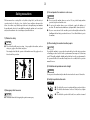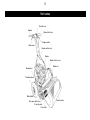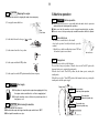
1
GREEN MOWER
LAWN MOWER
Owner's Handling Manual
LM56GA SN 14723 and onwards
LM66TA SN 10045 and onwards
Read this manual before using the machine.
1
CONTENTS
CONTENTS…………………………………………………………………………………… 1
Warning for Safety …………………………………………………………………………… 2
Greeting ……………………………………………………………………………………… 2
Safety precautions …………………………………………………………………………… 3
Part names …………………………………………………………………………………… 5
Features of LM56GA/LM66GA/LM66TA ………………………………………………… 6
Specifications ………………………………………………………………………………… 6
Handling ……………………………………………………………………………………… 6
1. Assembly and adjustment of main unit ………………………………………………… 6
1-1 Installing the handle…………………………………………………………………… 6
1-2 Installing the stand …………………………………………………………………… 7
1-3 Confirmation of the operation of clutch lever and brake lever …………………… 7
1-4 Connection of engine switch cord ………………………………………………… 7
2.Inspection before use ……………………………………………………………………… 8
2-1 Greasing ……………………………………………………………………………… 8
2-2 Inspection of engine oil ……………………………………………………………… 8
2-3 Inspection of wire ……………………………………………………………………… 8
3. Fastening of each portion ………………………………………………………………… 8
4.Engine starting sequence ………………………………………………………………… 8
WARNING Before starting engine …………………………………………… 8
4-1
CAUTION Starting the engine ………………………………………………… 8
4-2
CAUTION Stopping the engine………………………………………………… 9
4-3
DANGER Fuel supply ………………………………………………………… 9
4-4
4-5
CAUTION When leaving the machine ………………………………………… 9
5.Machine operation ………………………………………………………………………… 9
5-1
DANGER Before operation …………………………………………………… 9
5-2 Main clutch lever ……………………………………………………………………… 9
5-3 Change lever ………………………………………………………………………… 9
5-4 Groomer clutch lever …………………………………………………………………10
5-5 Adjustment of handle height …………………………………………………………10
WARNING Brake lever …………………………………………………………10
5-6
5-7 Throttle lever …………………………………………………………………………10
5-8 [IMPORTANT]Adjustment of engine clutch ……………………………………10
5-9 Clutch cover ……………………………………………………………………………11
5-10 Travelling wheel ……………………………………………………………………11
5-11[IMPORTANT]Adjustment of mowing height……………………………………11
5-12[IMPORTANT]Greasing …………………………………………………………11
5-13 Setting the mowing height gauge and blade thickness …………………………12
6. Blade engagement…………………………………………………………………………13
6-1[IMPORTANT]Lapping ……………………………………………………………13
6-2[IMPORTANT]Engagement ………………………………………………………13
6-3[IMPORTANT]Cam adjustment ……………………………………………………13
6-4 Cylindrical grinding and installation of blade reel cylinder ………………………14
6-5[IMPORTANT]Installation of blade reel cylinder …………………………………14
6-6 Attaching/detaching the small cover ………………………………………………14
6-7 Attaching/detaching the bottom blade base ………………………………………15
6-8 Machine number plate attaching position …………………………………………15
6-9 Specification for maintenance ………………………………………………………15
6-10 Position of mower during maintenance ……………………………………………15
7.Long-term storage …………………………………………………………………………15
8.
CAUTION Precautions for engine operation ………………………………………16
9.Maintenance Schedule ……………………………………………………………………16
Location of Labels ……………………………………………………………………………17
Understanding the machine safety labels …………………………………………………18
Warning for Safety
Greeting
Thank you very much for purchasing BARONESS GREEN MOWER.
This Owner's Handling Manual explains the method of correct handling, adjustment,
and maintenance of the mower. Thoroughly read the manual before operation. Carefully
read the engine operation manual before starting the engine. Mowers undergo
thoroughgoing trial operation and inspection before shipment. However, whether or not
the mower can exhibit the expected performance depends on the handling method,
inspection/adjustment before and after operation, and the properness of lubrication.
Handle the mower correctly for safe and excellent operation for an extended period of
time.
Warning marks indicate important items for safety.
Observe them strictly.
Warning Marks
Negligence of the warning will cause death or serious
DANGER injury.
WARNING
Negligence of the warning may cause death or serious
injury.
CAUTION Negligence of the warning may cause injury or
property damage.
See the Handling
Manual
Danger mark
Hand cut
Owner's Handling Manual
Precautions:
Danger mark
Foot cut
Engine switch lever
Fuel : Gasoline
Hot surface
Burn on hand
● The name of the model may be different when you make an inquiry about your
machine. Advise us of the machine number as well.
● The contents of this manual are subject to change without notice.
10h
Grease
CAUTION
Every 10hours
The warning marks attached to the machine indicate precautions for safety. Read them
carefully. Understand well the operating procedures and safety precautions before using
the machine. The marks and explanatory notes should be kept clean. If they are lost or
damaged, attach new marks. Never remove the warning marks attached to the machine.
CAUTION : Joint shaft
2
3
Safety precautions
3) Do not operate the machine in such cases.
WARNING
The lawn mower has a rotating blade reel cylinder (sharp blade), and the safety of
operation is subject to the place of use, obstacles, lawn conditions, and many other
factors. As a maker, we specifically request the user to thoroughly inspect and maintain
the machine, make efforts to become skilful in operating the machine, and correctly and
safely use the machine in order to avoid injury on yourself and others.
● Do not operate the machine when you are tired. If you get tired during machine
operation, stop the work and take a rest.
● Do not use the machine when you are sick, drunk, or under the influence of
medicine. The visual sensation, nimbleness, or judgment will be adversely affected.
● If you are unaccustomed to the machine operation, thoroughly understand the
handling method and safety precautions before use. Do not allow children to operate
the machine.
1) Clothes for safety
CAUTION
● Wear clothes that will prevent you from being caught in the machine, and wear
safety gear, goggles, shoes, helmet, and gloves.
It is strongly advised that the operators of this machine wear both goggles and ear
defenders for their protection.
4) When lending the machine to other people
CAUTION
If you lend the machine to a person who has no knowledge about the safety precautions
or handling procedure described in the operation manual, an unexpected accident may
result. Thoroughly explain the handling method and hand over the operation manual to
the person who will use the machine, having him or her carefully read the operation
manual before use.
5) Prohibition of operation or work at night
WARNING
Do not operate the machine at night or when the view is unclear because of bad weather.
6) Safety inspection before work
DANGER
2) Emergency relief measures
CAUTION
● Understand the method of stopping the engine in an emergency.
● Check that all covers are in position and that no portion is broken.
● Check that bolts and nuts are not loose. If they are loose, tighten
them.
● Check that the operation of the brake, levers, and tires is normal.
7) Precautions to take during operation
DANGER
CAUTION
DANGER
DANGER
8) Precautions as to inspection
● Check that there is no person or any object that may be broken
around the machine during operation.
● Check that there is no player in the vicinity, otherwise a flying golf
ball may hit against you.
● Exercise adequate care so that you will not get injured by flying
objects or the blade.
● Exercise special care when working on a slope or undulating ground.
The inclination of the machine should not exceed 25 degrees.
● Do not operate the machine in places where there is a risk of
toppling or slipping.
● Do not touch rotating parts during operation, otherwise you may
have your fingers or hands injured.
● Operate the machine at a speed that will allow the machine to stop
immediately in an emergency. Do not start the machine or operate
the handle suddenly. Be sure to move the machine at a slow speed
especially when descending a slope.
● Do not move the throttle lever abruptly to increase the speed,
otherwise the front of the machine may jump up.
● When you notice abnormal vibration, unusual sound, or other
abnormality in the machine, stop the engine immediately and
investigate the cause. Completely repair the machine before reuse.
● When leaving the machine, stop the machine on the level ground
and then stop the engine.
CAUTION
WARNING
● Place the machine on the level ground for inspection and repair.
Check that all parts are at rest.
● Clogging of the cooling air intake of the engine, air intake of the air
cleaner, muffler, and exhaust pipe with mown grass or other
foreign substances may cause fire due to engine malfunction or
overheating. Stop the work immediately, and remove the clogging
substance after the overheated section has cooled.
● Keep the warning marks and explanations clean at all times.
Replace them with new ones immediately when they are lost or
damaged.
● Do not remodel the machine.
● Use parts, oil, and grease specified by our company when changing
them.
● Remodeling or operation of the machine with some parts that are
not specified by our company may cause damage to the machine or
injury.
9) Moving on a public road
CAUTION
● Running the machine on a public road while you are riding on a
sulky is prohibited by the law. Walk and move the machine on a
public road.
10) Storage
● Wait until the engine cools when covering the machine with a
sheet, etc.
● Remove gasoline when the machine will not be operated for more
than six months.
4
5
Part names
Throttle lever
Handle
Main clutch lever
Engine switch
Brake lever
Engine switch cord
Engine
Engine clutch cover
Blade reel
Drum wheel
Travelling wheel
Wheel Shaft
Groomer clutch lever
Front groomer
Front roller
Grass catcher
Front groomer
Features of LM56GA・66GA・66TA
Dethatching reel
Dethatching brush
of
of
Working width Number
Working width Number
Working width
blades
blades
● The lightest green mower of all models of this class
● The weight balance and undulation following performance have been improved for
better green mowing.
● The newly-designed handle improves the operability, lessening the operator's fatigue.
● The structure of the clutch has been changed for smooth starting.
●LM56GAF・66GAF are equipped with Front Groomer.
● The front groomer is provided to permit normal and reverse rotation.
(Provided with a groomer.)
(cm)
(cm)
Turning
diameter
(cm)
(cm)
LM56 Series
51
78
50
39
49
6
LM66 Series
60
92
60
46
57
6
Handling
1. Assembly and adjustment of main unit
1-1
Specifications
Model
LM56GA
(GAF)LM66GA
(GAF) LM66TA
Length (with grass catcher)
Width (without travelling wheel)
150cm
94.2cm
Height (handle)
103.2cm
Left-side lower edge of handle
103cm
Washer
Main unit (without catcher and wheel) 81kg(85kg)87kg(91kg)
Weight Grass catcher
3.3kg
Mowing width
Mowing Reel diameter
section Number of reel blades
Mowing height
Engine
Speed (Km/h)
86kg
Right-side lower edge of handle
Bolt
3.6kg
6.9kg
Travelling wheels (2 pcs)
Installing the handle
1) Put the handle pin on the left frame into the hole at the left-side lower edge of the
handle.
2) While pressing the right-side lower edge of the handle inward, put the handle pin of the
right frame into the hole.
3) Secure the lower edge (slotted section) of the right and left handles to the frame from
the back with the bolt, conical spring washer, and washer.
55.6cm
※
While pressing the
right-side lower edge
of the handle inward,
put the handle pin
Conical spring washer
64.6cm
φ12.8cm
9 or 11 blades
7 blades
3.0∼29mm(3.0∼27mm) 7.0∼29mm
Handle pin
(Left frame)
Robin EX13D 3.2kw(4.3ps)/4000rpm
4.8km/h(3000rpm)
4.4km/h
(3000rpm)
Handle pin (Right frame)
6
7
1-2
1-3
Installing the stand
1) Temporarily secure the left side of the stand to the frame with the bolt, washer
(inside), and nut (outside).
2) Put the spring on the projection of the frame and the projection at the right edge of the
stand.
3) While pulling the right side of the stand backward, make alignment with the hole in
the frame, and secure the stand with the bolt, washer (inside), and nut (outside).
4) Tighten the bolt, washer, and nut at the left side of the stand that were temporarily
secured.
Confirmation of the operation of clutch lever and brake lever
Check that the clutch and brake operate completely.
When adjustment is necessary, make adjustment according to "5-8. [Important]
Adjustment of engine clutch section."
1-4
Connection of engine switch cord
When assembling the handle, check the connection of the engine switch cord. There are
two connections - plug and crimp terminal.
1) The plug is connected to the plug that is connected to the engine.
WARNING
2) The crimp terminal is secured to the engine crankcase with a hexagon bolt. When the
connection of the engine switch cord is incomplete, the engine will not stop even if the
engine switch is operated. Check that the cord is correctly connected.
Put the spring on the projection.
Plug
Temporarily secure the
left side of the stand.
Crimp terminal
Tighten the
left side of
the stand.
While pulling the right side
of the stand backward,
make alignment with the
hole and secure the stand.
4.Engine starting sequence
2.Inspection before use
2-1
10h
2-2
4-1
Greasing
The transmission and intermediate transmission gears are equipped
with needle bearings. Grease them every 10 hours. Shortage of grease
will cause damage to the needle bearings.
Before starting engine
Carefully read the gasoline engine operation manual before starting the engine. The
handle cover is equipped with an engine switch. Check the "ON/OFF" positions. Set the
engine switch lever in the ON position, set all moving parts in the neutral position. Check
for safety - covers are in position and not damaged and there is no person around the
machine - before starting the engine. Do not start the engine indoors without an
appropriate ventilator.
Inspection of engine oil
Replenish the engine with engine oil. (A correct level will be shown when the engine is
placed horizontally.) Change engine oil 8 hours after the initial operation, and every 50
hours from the second time onward. Oil : SAE30.
4-2
2-3
WARNING
CAUTION
Starting the engine
Inspection of wire
Check that the clutch wire and brake wire are normal.
1) Do not grip the main clutch lever.
Main
Clutch lever
3. Fastening of each portion
2) Set the throttle lever in the high-speed
Many parts are fastened by bolts. Bolts and nuts may be loosened some time after initial
operation. Fasten them to the specified torque.
position.
High-speed
Appropriate fastening torque N.m (kgf-cm)
M6
M8
M10
M16
3) Set the engine switch in the ON position.
Normal bolt Heat treated bolt
8(80)
18(180)
36(360)
36(360)
72(720)
1.5-pitch left-hand thread: 36(360)
4) Set the strainer lever in the open position.
OFF
ON
Open
5) Pull the choke lever and pull the recoil starter, and the engine will start.
6) Return the choke lever.
8
9
4-3
CAUTION
Stopping the engine
5.Machine operation
※Remember the method for stopping the engine in an emergency.
5-1
1) Do not grip the main clutch lever.
Main
Clutch lever
DANGER Before operation
● Check that each portion - especially the brake and clutch - operates
satisfactorily before starting machine operation.
● Make sure that the machine can be stopped immediately at any time.
● Exercise care so that you and people around the machine will not be injured.
5-2
2) Set the throttle lever in the low-speed
position.
Main clutch lever
The clutch lever is on the left side of the handle.
Avoid quick operation. Carefully and slowly operate the
machine.
※ Grip the lever, and the travelling drive is turned "ON" and
the machine begins to move forward.
Low-speed
3) Set the strainer lever in the close position.
Close
5-3
4) Set the engine switch in the OFF position.
OFF
ON
5) Set the engine lever in the OFF position immediately in an emergency.
4-4
DANGER
Fuel supply
● Keep flame etc. away from the engine when supplying fuel. Stop
the engine outdoors and allow it to cool before supplying fuel.
● Keep the machine clean at all times to prevent deposition of
dust,grease, or oil.
4-5
CAUTION
When leaving the machine
● Park the machine on a flat place.
● Check that the engine has stopped and the engine switch lever is "OFF."
● Do not park the machine on a slope.
ON
OFF
Main clutch lever
Change lever
The change lever is at the top of the left frame.
There are three changeover positions. When the lever is in the "Reel ON" position, the
drum and cutter operate, entering the mowing mode.
When the lever is in the "Travel ON" position, only the drum operates, entering the
traveling mode.
When the lever is on the "Travel OFF" position, both drum and cutter stop, entering the
traveling mode with the engine stopped.
Change lever
Reel ON
operation
(Drum
Blade reel cylinder operation
Drum operation
Travel ON (
Blade reel cylinder stop
Travel OFF
cutter stop
(Drum
Blade reel cylinder stop
5-4
5-7
Groomer clutch lever
The lever is at the top of the groomer gear case on the outside of the right frame.
There are three changeover positions - "Normal rotation" (in the same direction as the
rotating direction of the blade reel cylinder), "Rotation stop," and "Reverse rotation" (in
the direction opposite to the direction of rotation of the blade reel cylinder). Change the
positions according to the type of work.
5-8
Normal rotation
[IMPORTANT]Adjustment of engine clutch
《When reinstalling the engine》
Adjust the clearance between the engine clutch and clutch facing so that it will be approx.
0.5 to 1 mm when the travelling clutch is engaged. For adjustment, loosen the four bolts
that are securing the engine, and insert a thickness gauge (attached) into the front and
rear. Make adjustment so that the gap will be parallel, and then fasten the bolts.
Rotation stop
《When adjusting the clutch wire》
Make adjustment so that the operation distance of the clutch plate between the clutch
engagment and disengagement will be 0.8-1 mm.
Reverse rotation
5-5
Throttle lever
The throttle lever is on the left side of the handle. The lever controls
the engine speed. The speed of rotation is 1,400 - 3,400 rpm.
Operate at about 3,000 rpm.
Adjustment of handle height
Clutch wire adjusting nut
Move the securing bolt up and down in the slot of the handle guide, which is securing the
handle to the frame, in order to adjust the height of the handle according to the operator's
working position.
Clearance
0.5∼1.0mm
Engine clutch
5-6
WARNING
Brake lever
The lever is in the right-side grip section of the handle. Grip the lever, and the internal
expanding brake set in the second shaft section will operate.
The strength can be adjusted by the screw.
10
Clutch facing
1.0∼2.0mm
Operation distance
11
5-9
5-12 [IMPORTANT] Greasing
fasten
Clutch cover
The clutch cover is on the left side of
the engine, covering the engine clutch.
It is secured by turning the fastenbolt
clockwise (by 4-5 turns).
fastenbolt
open
Periodically fill up respective grease nipples.
Exercise special care when greasing the sections where needle bearings are used.
(Intermediate shaft of the right and left gears and the intermediate shaft of the groomer)
Periodically fill up the grease nipples with approx. 1 g of grease (EXCELITE EP No.2)
(one or two times with a compact manual grease pump).
Every 10 hr
clutch cover
5-10 Travelling wheel
The travelling wheel is used to move the machine from green to green. Set the stand up
right, pull the tire holding the lever, and the wheel will come off.
※tire air pressure 120kPa(1.2kg/cm2)
Left frame intermediate shaft (for Reel)
Left gear cover
Right & left frame intermediate shaft (for Drum)
Reel bearing
Differential gear parts
Front roller
Vertical gear case intermediate shaft
Vertical gear case
Right-side main unit
5-11 [IMPORTANT] Adjustment of mowing height
Move the front roller up or down, and the mowing height can be adjusted to a maximum
of 27 mm. Use an optional bottom blade when 3 m/m mowingheight is desired.
Drum
Blade reed cylinder
Every 10 hr
Every 50 hr
Front roller
mowing
height
Front groomer
Bottom blade
Every 50 hr
Left-side main unit
5-13 Setting the mowing height gauge and blade thickness
4)[IMPORTANT] Adjustment of front roller height
Bring the mowing height gauge into contact with the front roller and drum (as shown
below), and adjust the height of the bottom blade.
a. Loosen the tall nut of the roller bracket, and move the front roller up or down with
roller adjuster.
b. Position the front roller with the mowing height gauge.
c. Make adjustment at both edges.
d. Tighten the tall nut, and secure the roller bracket.
1) Set the mowing height gauge at the desired height. The minimum mowing height
with respect to each bottom blade thickness is shown below.
Blade Min.mowing
Type of
thickness
blade
height(mm)
(mm)
Standard
blade
LM56GA
Tipped
blade
Standard
blade
LM66GA
Tipped
blade
Code No.
Part Name
1.5
3.0
K2511000270 1.5 bottom blade 55G
2
3.5
K2511000280
2.5
4.0
K2511000050 2.5 bottom blade 55G
3
4.5
K2510000060
3 bottom blade 62.5-559 standard
5
7.0
K2510000160
5 bottom blade 62.5-559
1.5
3.0
K2511000310 1.5 bottom blade 65G
2 bottom blade 55G
2
3.5
K2511000300
2.5
4.0
K2511000200 2.5 bottom blade 65G
3
4.5
K2510000150
3 bottom blade 62.5-648.4
5
7.0
K2510000170
5 bottom blade 62.5-648.4
Option
Front roller
Option
Front groomer
Blade reel cylinder
Drum
2 bottom blade 65G
Standard blade
Blade thickness
Note
standard
Option
Small screw for
Dethatching
Small screw for
mowing height
Bottom blade
Tipped blade
Mowing height gauge
Blade thickness
※ The minimum mowing height is the height on the average condition green. Lawn may
be shaved when the undulation of the green is substantial. Set the mowing height
higher in that case.
2) Adjust the front gloomer according to the condition of the green before use.
※ If the groomer blades are set deeper than the ground surface, the shaft may bend.
※ The front groomer, when it is put too low, will apply an excessive load to the engine
and transmission section, causing malfunction or failure.
3) When using the grooming brush, adjust the height so that it will be equal to the
mowing height.
※ The brush will be worn easily when the height is too low.
12
13
6. Blade engagement
Check that the engine is at rest before making adjustment.
Grind and adjust the blade reel cylinder and bottom blade entirely so that a
newspaper will be cut sharply.
6-1
[IMPORTANT] Lapping
Conduct lapping after mowing operation (before adjusting the engagement).
1) Check the entire portion of the blade reel cylinder to check which portion is dull. (If a
newspaper cannot be cut in any portion, put in two sheets of paper to carefully check
which portion is dull.)
2) Connect the lapping machine (RM20B) or lapping bolt (option) to the lapping shaft of
the mower.
3) Rotate the blade reel cylinder in the direction opposite to the mowing direction, and
apply abrasive with a brush only to the portion where a newspaper was sharply cut.
The portion where a newspaper was not cut is worn away. Do not apply abrasive to
such portions.
※The right side (when viewed from the front of the blade reel cylinder) of the blade
reel cylinder will be worn away 3-4 times earlier than the left side. When applying
abrasive to the blade reel cylinder, be sure to move the brush from left to right. (See
right sketch)When the abrasive is a mixture of powder (#200∼#400) and oil, mix
them at the rate of 1:3 to 4. The gel compound (option) can be used as it is.
4) Keep rotating the blade reel cylinder, and stop rotation when the contact sound
disappears. Put in a newspaper again to check the blade reel cylinder entirely for the
sharpness of each portion.
5) Repeat operations (3) and (4). When the blade reel cylinder and bottom blade are in
contact with each other uniformly, apply abrasive to the blade reel cylinder entirely for
final lapping.
6) After lapping, remove the abrasive with steam, etc.
CAUTION
Both blade reel cylinder and bottom blade are edged. Handle them
carefully.
Be careful of the fingers, which turn the blade reel cylinder, when
cutting a newspaper to check sharpness. Uniformly lap the right and
left sides of the bottom blade in contact with the blade reel cylinder, and
the life of the blade will be maximized.
6-2
[IMPORTANT]Engagement
1) Lightly engage the blade reel cylinder and bottom blade uniformly on both sides.
2) Uniformly adjust the bottom blade on the right and left sides.
Turn the blade adjusting nut clockwise for slight engagement, and turn it
counterclockwise for firm engagement.
3) Lightly engage both sides to the extent that a newspaper will be cut sharply.
When the blade reel cylinder is worn and the spring pressure decreases, adjust the
spring pressure by the spring adjusting screw and 14 nut. (Make adjustment so that
the spring will be 50 mm long.)
gth
g len
n
i
r
Sp 0mm
5
Blade adjusting nut
Move the brush
from left to right
6-3
[IMPORTANT] Cam adjustment
Turn the cam bush on both sides of the bottom blade, and the blade will be raised and
lowered within a maximum range of 0.3 mm. The above method is used when the edges
of the blade reel cylinder and bottom blade are not in parallel.
1) When there is a gap between the blade reel cylinder and the left frame side of the
bottom blade loosen the lock nut, and turn the left cam bush clockwise as much as the
gap. Turn it clockwise by 30°
to raise the bottom blade by 0.1 mm. After adjustment,
firmly fasten the lock nut.
2) When there is a gap on the right frame side, loosen the lock nut, and turn the right cam
bush counterclockwise as much as the gap.
Center of cutter pin
1) Replace the bearings and reel shaft seals on both sides of the blade reel cylinder. Use
the bearing 30204JRP6 that has the smallest error.
0.3
Cam adjustment
2) Sufficiently apply grease (EXCELITE EPNO2) to the bearing and seal. (Apply grease
to the bearing while turning the roller.)
The bottom blade rises
3) Method to fasten nut after installing the blade reel cylinder
[IMPORTANT]Tighten the nut until the length of the spring reaches 11.5 mm, and lock
the nut. A certain preload will be applied by the spring pressure. The rotational torque of
the blade reel cylinder should be 0.8∼1.0N・m(8∼10kgf・cm). If it is not, check the
The bottom blade lowers
bearing and seal.
Center of cam bush
6-4
6-6
Cylindrical grinding and installation of blade reel cylinder
Remove the lapping bolt and the gear retainer collar in this order, and then remove the
left small cover.
Attach the left small cover, and then attach the gear retainer collar and lapping bolt in this
order. (Attach the left small cover so that the reel cutter shaft will be at the center of the
oil seal of the left small cover.)
Cylindrically grind the blade reel cylinder when it is worn away and has become conical.
(Ask the dealer you purchased the machine from for cylindrical grinding.)
6-5
Attaching/detaching the small cover
[IMPORTANT] Installation of blade reel cylinder
2 SPCC washer 1635
16 Left hand thread nut 3P1.5
Non Groomer
Left small cover
reel gear securing nut
Gear retainer collar
Groomer Model
10 disk spring H
Lapping bolt
Torgue wrench
20 tooth reel gear
14
15
6-7
Attaching/detaching the bottom blade base
Remove the bottom blade base arm, and then remove the bottom blade base.
Attach the bottom blade base, and then attach the bottom blade base arm.
Bottom blade base arm
Bottom blade base arm
6-9
Specification for maintenance
Qty of engine oil
0.6dm3(0.6L)
Plug
NGK BR4HS
Capacity of gasoline tank
2.5dm3(2.5L)
Tire air pressure
120kpa(1.2kg/cm2)
Engine speed
1400∼3400rpm
Loosen.
Tighten.
Loosen.
Tighten.
Loosen.
Bottom blade base
6-8
Tighten.
6-10 Position of mower during maintenance
If the mower handle is left leaned on the ground for a long time during maintenance,
engine oil may enter the engine combustion chamber and cause the engine to run
improperly.
Be careful not to keep this position long.
Machine number plate attaching position
The type and serial number are marked on the machine number plate.
It is attached to the upper portion on the left side of the front frame stay.
7.Long-term storage
1) For the engine, refer to the engine operation manual.
Machine number plate
2) Cylindrically grind the blade reel cylinder every six months.
3) Replace the bearing (30204JRP6) and seal on both sides of the blade reel cylinder
every season. (Replace them even if they have not been used for many hours.)
4)Clean the machine, and apply grease or oil to respective sliding sections.
8.
CAUTION
9) When the machine is to be stored for a long time exceeding 5
months, remove gasoline from the engine.
Precautions for engine operation
For the engine, refer to the engine operation manual.
1) Use gasoline for automobiles as the fuel of the engine.
10) Engine maintenance schedule
To keep the engine in satisfactory status at all times, be sure to
conduct maintenance and inspection according to the following
table:
2) Completely change engine oil when the machine has been used for
eight hours after the initial operation, because the machine is used
under tough conditions with vibration and dust, and change oil every
50 hours after that. The quantity of engine oil is 0.6 dm3 (0.6L). Use
SAE30.
9.Maintenance Schedule
Engine
Maintenance
3) Always cover the suction port of the air cleaner with a cleaner cover
bag during operation. Be sure to clean the air cleaner element
before using the machine.
DANGER
4) Fire is strictly prohibited during fuel supply. Be careful of a lit
cigarette. Replenish the fuel tank outdoors after the stopped engine
has been cooled. Wipe off the spilt fuel completely.
Before use Every 8hr Every 10hr Every 50hr
Cleaning of each part/inspection of tightening
○
Inspection and addition of fuel
○
Inspection and cleaning of air cleaner
○
Inspection and addition of engine oil
○
only after the
initial operation
Engine oil change
Main unit
5) Do not start the engine in a building without a proper ventilator.
Maintenance
CAUTION
6) The muffler and the area around the exhaust port of the muffler will
become hot. Do not bring gasoline, matches, dry grass, or other
inflammables near hot portions.
Every 8hr Every 10hr Every 50hr
Inspection and cleaning of recoil starter dust proofing net
○
Cleaning of each part/inspection of tightening
○
Inspection and adjustment of blade engagement
○
Inspection and adjustment of mowing height
○
○
Greasing and oiling
CAUTION
7) Inspection before operation
Check the joint of fuel pipe, etc. for looseness or damage. Check
bolts and nuts in respective sections for looseness.
CAUTION
8) Wear appropriate clothes. An apron, towel on the belt, long string,
etc. will cause you to be caught in rotating parts.
○
Removal of mown grass and dust
16
○
○
17
Location of Labels for LM56GA and LM66TA
Code No.
Right-side of the main unit
Part Name
Qty
/Unit
1
12
3
2
K4203001040
Clutch Mark
1
3
K4205001300
Engine oil Warning Mark
1
4
K4205001330
Noise Warning Mark
1
5
K4209000880
LWA 98 Mark
1
6
K4203001110
Clutch Mark (Large)
1
7
K4205001590
"Handle with care" label
1
8
K4205001600
"Cutting Warning" label
1
9
K4203001120
Groomer Mode Selector
1
10
K4209000370
Grease Up 10h Mark
2
11
K4203000970
BRAKE Mark
1
12
R073−20051−81 Warning Mark
5
4
Rear of the main unit
1
Understanding the machine safety labels
①Use only unleaded gasoline.
①
⑤
⑤Stop the engine and wait for
moving parts to stop.
②
②Read the owner's manual.
③
K4205001600
③keep a safe distance from the
machine.
⑥
⑥It is strongly advised that the
operators of this machine wear ear
defenders for their protection.
④
④Do not open or remove safety
shields while engine is
running.
K4205001330
⑦
⑧
⑦Stay clear of the hot surface.
②
⑧Exhaust gas is poisonous.
Do not operate in an unventilated
area.
⑨Stop the engine before refueling.
⑨
K4205001590
18
⑩
R073-20051-81
⑩Fire, open flame and smoking
prohibited.
Head Office
1-26, Miyuki-cho, Toyokawa,
Aichi-Pref. 442-8530 Japan.
Turf Care Machinery
Tel : (0533)84-1390
Fax : (0533)89-3623
LM56GA--UM--GBZ/10D-00-OZEKI