1
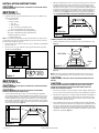
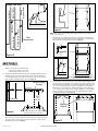
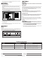
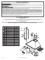
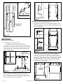
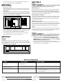
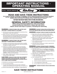
IMPORTANT INSTRUCTIONS OPERATING MANUAL
Models:ESVAL30,
ESVAL36
Range Hood
READ AND SAVE THESE INSTRUCTIONS
READ CAREFULLY BEFORE ATTEMPTING TO ASSEMBLE, INSTALL, OPERATE OR MAINTAIN THE PRODUCT DESCRIBED.
PROTECT YOURSELF AND OTHERS BY OBSERVING ALL SAFETY INFORMATION. FAILURE TO COMPLY WITH
INSTRUCTIONS COULD RESULT IN PERSONAL INJURY AND/OR PROPERTY DAMAGE!
RETAIN INSTRUCTIONS FOR FUTURE REFERENCE.
GENERAL SAFETY INFORMATION
When using electrical appliances, basic precautions
should always be followed to reduce the risk of fire,
electric shock and injury to person, including the following:
WARNING: TO REDUCE THE RISK OF FIRE, ELECTRIC SHOCK AND
TO REDUCE THE RISK OF FIRE, ELECTRIC SHOCK, DO NOT USE THIS FAN
WITH ANY SOLID-STATE SPEED CONTROL DEVICE.
a) Use this unit only in the manner intended by the manufacturer.If you have
questions, contact the manufacturer.
b) Before servicing or cleaning the unit, switch power off at service panel
and lock the service disconnecting means to prevent power from
being switched on accidentally. When the service disconnecting means
cannot be locked, securely fasten a prominent warning device, such as
a tag, to the service panel.
TO REDUCE THE RISK OF A RANGE TOP GREASE FIRE:
INJURY TO PERSON, OBSERVE THE FOLLOWING:
WARNING: TO REDUCE THE RISK OF FIRE, ELECTRIC SHOCK AND
INJURY TO PERSON, OBSERVE THE FOLLOWING:
a) Installation work and electrical wiring must be done by qualified
person(s) in accordance with all applicable codes and standards,
including fire-related construction.
b) Sufficient air is needed for proper combustion and exhausting of gases
through the flue (chimney) of fuel burning equipment to prevent back
drafting. Follow the heating equipment manufacturer’s guideline and
safety standards such as those published by the National Fire Protection
Association (NFPA) and the American Society for Heating, Refrigeration,
and Air Conditioning Engineers (ASHRAE), and the local code authorities.
c) When cutting or drilling into wall or ceiling, do not damage electrical
wiring and other hidden utilities.
CAUTION: TO REDUCE THE RISK OF FIRE AND TO PROPERLY
EXHAUST AIR, BE SURE TO DUCT AIR OUTSIDE - DO NOT VENT
EXHAUST AIR INTO SPACES WITHIN WALLS OR CEILINGS OR INTO
ATTICS, CRAWL SPACES, OR GARAGES.
d) Ducted fans must always be vented to the outdoors.
e) This unit must be grounded.
f) To avoid motor bearing damage and noisy and/or unbalanced impellers,
keep drywall spray, construction dust, etc. off power unit.
g) Read all instructions before installing or using range hood.
a) Never leave surface units unattended at high settings. Boilovers
cause smoking and greasy spillovers that may ignite. Heat oils
slowly on low or medium settings.
b) Always turn hood ON when cooking at high heat or when
flambéing food (ie. Crepes Suzette, Cherries Jubilee,
Peppercorn Beef Flambé).
c) Clean ventilating fans frequently. Grease should not be allowed to
accumulate on fan filter.
d) Use proper pan size. Always use cookware appropriate for the size
of the surface element.
TO REDUCE THE RISK OF INJURY TO PERSONS IN THE EVENT OF A RANGE
TOP GREASE FIRE, OBSERVE THE FOLLOWING:
a) SMOTHER FLAMES with a close-fitting lid, cookie sheet, or metal
tray, then turn off burner. BE CAREFUL TO PREVENT BURNS. If the
flames do not go out immediately, EVACUATE AND CALL THE FIRE
DEPARTMENT.
b) NEVER PICK UP A FLAMING PAN - You may be burned.
c) DO NOT USE WATER, including wet dishcloths or towels a violent steam explosion will result.
d) Use an extinguisher ONLY if:
I. You know you have a Class ABC extinguisher, and you
already know how to operate it.
II. The fire is small and contained in the area where it started.
III. The fire department is being called.
IV. You can fight the fire with your back to an exit.
TO REDUCE THE RISK OF FIRE, USE ONLY METAL DUCTWORK.
SAVE THESE INSTRUCTIONS
6728027 Rev. G 5-12
www.airkinglimited.com
1 of 12
INSTALLATION INSTRUCTIONS
CAUTION: MAKE SURE POWER IS SWITCHED OFF AT SERVICE PANEL BEFORE
STARTING INSTALLATION.
SECTION 1
Preparing the Range Hood
2. With the hood hanging in place from the top screws, mark the location of the lower holes.
If installing onto drywall, remove the hood and drill holes into wall using a 3/16" drill
bit. Install wall anchors into the drilled holes (one for each hole). If installing into other
material (brick, cement, plaster, etc.) choose an appropriate fastner capable of supporting
the weight of the hood. Hang the hood over the keyhole anchors and verify that the hood is
centered, level and the bottom holes line up with the anchors. Install the provided #6 x 1"
screws into the anchors (Figure 3). Tighten all screws completely and reinstall the Grease
filters. ALL DUCTING MUST COMPLY WITH LOCAL AND NATIONAL BUILDING CODES.
1. Unpack hood from the carton and confirm that all pieces are present. In addition to the
range hood you should have:
2 - Chimney Sections
1 - Package containing:
1 - duct collar
2 - chimney brackets
8 - #6 x 1" mounting screws with wall anchors
2 - #6 x 3/8" self threading screws (chimney upper)
30" models: 2 - Aluminum Grease Filters (shipped installed)
36" models: 3 - Aluminum Grease Filters (shipped installed)
1 - GU24 Base, 26W Fluorescent Lamp
1 - Instruction/Safety Sheet
NOTE: Some hoods may be shipped with a protective plastic adhered to the range hood. It is
recommended to leave this in place during installation to protect the hood from scratching.
Remove when the installation is complete.
2. Lay the back side of the hood flat on a table. Use a piece of cardboard to avoid damaging
the table or the hood.
Holes
Side View
Figure 3
TO REDUCE THE RISK OF FIRE, USE ONLY METAL DUCTWORK.
1. Install the included duct collar to the hood with two of the provided #6 blunt tip screws
(Figure 4).
Ducting
3. Remove the lens cover on the underside of the range hood and install the included 26
watt fluorescent lamp (Figure 1).
Duct Collar
Hood
Figure 4
Lamp
NOTE: To achieve proper air flow, 6" round ducting is required. The duct connector is 5.8" in
diameter (for 6" round ducting) and the center is located 3.1875" inches from the back wall.
Pin
Figure 1
1. Connect the ducting to the duct collar and secure in place using tape to seal all joints
(Figure 4).
CAUTION:
ROOF CAP.
SECTION 2
Installing the Range Hood
CAUTION: MAKE SURE POWER IS SWITCHED OFF AT SERVICE PANEL BEFORE
STARTING INSTALLATION.
CAUTION:WHEN CUTTING OR DRILLING INTO WALL DO NOT DAMAGE
ELECTRICAL WIRING AND OTHER HIDDEN UTILITIES.
1. Locate and mark the upper keyhole positions on the wall. If installing onto drywall, drill
holes into wall using a 3/16" drill bit. Install wall anchors into the drilled holes (one for each
hole). Install (2) provided #6 x 1" screws, leaving a 1/8" gap between the screw head and
the wall. If installing into other material (brick, cement, plaster, etc.) choose an appropriate
fastner capable of supporting the weight of the hood. Line up the keyholes in the hood with
the screws and position in place. Hang the hood over the keyhole anchors and verify that the
hood is centered, plum and level (Figure 2).
Upper Keyholes
ALWAYS DUCT THE FAN TO THE OUTSIDE THROUGH A WALL OR
CAUTION:
ALL ELECTRICAL CONNECTIONS MUST BE MADE IN ACCORDANCE
WITH LOCAL CODES, ORDINANCES, OR NATIONAL ELECTRICAL CODE. IF YOU ARE
UNFAMILIAR WITH METHODS OF INSTALLING ELECTRICAL WIRING, SECURE THE
SERVICES OF A QUALIFIED ELECTRICIAN.
1. Remove wire compartment cover by removing the screw then sliding it outward. Choose
the most convenient electrical knockout and remove using a straight-blade screw driver.
2. Run wiring from an approved source carrying the appropriate rating. One neutral (White), one
ground (green or bare copper), and one hot (Black). Secure the electrical wires to the wire
compartment with an approved electrical connector. Make sure you leave enough wiring in
the box to make the connection to the hood.
3.
Connect the White wire from the range hood to the White wire from the supply, and the Black
wire from the range hood to the Black wire of the supply. Connect the ground wire from the
home (green or bare) and the Green wire from the range hood. Use approved methods for
all connections. Reinstall the wire compartment by sliding the tabs back into the holes then
reinstalling the screw that was removed eariler. Make sure all wiring is securely contained
within the wire compartment (Figure 5).
Side View
Figure 2
6728027 Rev. G 5-12
www.airkinglimited.com
2 of 12
Ground
(Green or Bare)
Ground (Green or Bare)
Neutral (White)
Neutral (White)
Hot (Black)
Hot (Black)
Supply from home
B
B
A
A
Figure 7
NOTE: If the top chimney section (included) will be installed, slide the top section inside of the
bottom section at this point.
Wire
Compartment
3.
Slide chimney in place so top tabs of the chimney are secured in place on the indents of the
vertical chimney bracket and the backside of the chimney fits between the hood and the wall
with the bottom tabs overlapping the back lip of the hood (Figure 8).
From Hood
Figure 5
SECTION 5
Attaching the Chimney
1. Mark the location for the vertical chimney bracket:
If using the upper chimney section: 9-3/4"
If not using upper chimney section: 15-3/4"
2. If installing onto drywall, drill holes into wall using a 3/16" drill bit. Install wall anchors into
the drilled holes (one for each hole). Secure bracket into place with (2) provided #6 x 1"
screws. If installing into other material (brick, cement, plaster, etc.) choose an appropriate
fastner capable of supporting the weight of the chimney (Figure 6).
Vertical Chimney
Bracket
Side View
Figure 8
Details of duct collar, ducting, and electrical have been
omitted from drawing for clarity purposes.
4. To install the upper section, mark the location of the included horizontal mounting bracket
using the bracket as a template. Make sure the bracket is level and in line with the bottom
section. The height will be dependent on your installation requirements. Make sure the slots
in the side of the chimney will match the holes in the mounting bracket. If installing onto
drywall, drill holes into wall using a 3/16" drill bit. Install wall anchors into the drilled holes
(one for each hole). Secure bracket into place with (2) provided #6 x 1" screws. If installing
into other material (brick, cement, plaster, etc.) choose an appropriate fastner capable of
supporting the weight of the chimney (Figure 9).
9-3/4"
or
15-3/4"
Mounting
Bracket
Figure 6
Details of duct collar, ducting, and electrical have been
omitted from drawing for clarity purposes.
3. Press in appropriate tabs on lower chimney section (section with vent holes). If using the
upper chimney, press in tabs in middle of the chimney (Position A), otherwise press in tabs
at top of the chimney (Position B). Press in tabs at the bottom of the chimney so there is
approximately 1/4" of clearance (Figure 7).
6728027 Rev. G 5-12
Figure 9
www.airkinglimited.com
3 of 12
5. Raise top chimney in place over horizontal mounting bracket and secure in place with
the two included #6 x 3/8" screws (Figure 9).
SECTION 6
SECTION 8
Maintenance
CAUTION:
Finishing the Installation
SERVICING THE UNIT.
1. Install the appropriate filters.
Charcoal Filters: If the range hood will be run ductless, remove and discard the grease
filters that were included with the unit and install model BCCF-02 charcoal filters
instead.
Grease Filters: If the range hood will be vented to the exterior of the home, install the
grease filters supplied with the hood by sliding tab at rear of filter into slot in hood.
While holding in handle of filter, lift filter into palce and release handle. the filter should
snap securely into place (Figure 10).
MAKE SURE POWER IS SWITCHED OFF AT SERVICE PANEL BEFORE
Grease Filters
Included with your range hood are aluminum grease filters that should be washed at least once
a month. The filters are dishwasher safe and should be washed in a mild soap or detergent.
Refer to Step 3 of Section 1 Preparing the Range Hood, to remove filters. If the grease filters
become damaged, replace with Air King Model BCGF-01 Grease Filter.
Charcoal Odor Filter
If you have installed the optional charcoal odor filters, they cannot be washed and must be
discarded and replaced when they become noticeably dirty, have stopped filtering the odors, or
at least once per year. Replace with Air King Model BCCF-02 Odor Filters.
Changing the Lamp
Remove the lamp cover on the underside of the hood. Remove lamp by gently twisting the lamp
base counterclockwise while applying outward pressure. Installation is the reverse of removal.
Replace with Air King model 26SBL or a compatible GU24 26 watt self ballasted lamp.
Fuse
Filter
Figure 10
To replace the fuse, turn the fuse cap located next to the wire connector counter clockwise
and pull out. Replace with a Bussman MDA 125-Volt, 1.5 Amp Max. fuse (models VAL30AB and
VAL36AB utilize a 3 Amp Max fuse). Reinstall the fuse back into the hood.
2. Remove any protective plastic adhered to the range hood.
Cleaning
3. Turn switches to the OFF ( • ) position and restore power. Test that the light and the fan
are operating properly.
AS THEY MAY DAMAGE THE RANGE HOOD.
CAUTION: DO NOT USE GASOLINE, BENZINE, THINNER, HARSH CLEANSERS, ETC.,
4. If there is any vibration noise, check for the source and try to tighten fasteners or adjust
the tape to make a tighter connection or seal.
1. Clean your range hood with a mild detergent, such as dishwashing liquid, and dry with a soft
cloth. NEVER USE ANY ABRASIVE PADS OR SCOURING POWDERS. Completely dry before
restoring power. NEVER IMMERSE ELECTRICAL PARTS IN WATER.
SECTION 7
2. The fan assembly can be vacuumed when build up (dirt, lint, etc.) accumulates over time.
The fan is permanently lubricated and does not require oiling.
Operation
Controls
Your Range Hood is equipped with two sliding switches with one controlling the lighting and the other
controlling the exhaust fan. The light control has two positions, ON ( I ) and OFF ( O ). The fan is a four
position control, HIGH (III), MEDIUM (II),LOW (I), and OFF ( • ) (Figure 11).
Figure 11
Troubleshooting Guide
Trouble
Probable Cause
1. Hood does not operate when the switch is on.
1a.
A fuse may be blown or a circuit tripped.
1a. Replace fuse or reset circuit breaker.
Suggested Remedy
1b.
Wiring is not connected properly.
1b. Turn off power to unit. Check that all wires are connected.
2. Hood is operating, but air moves slower than normal.
2.
Obstruction in the exhaust ducting.
2.
3. Hood is making a rattling noise.
3a.
Filters are loose.
3a. Turn off power to unit. Check that all filter are securely in place.
3b.
Duct connection is loose.
3b. Turn off power to unit. Check that duct connection is tight.
Check for any obstructions in the ducting including filter.
Installer:
Installation Date:
Place of Purchase:
Model Number:
6728027 Rev. G 5-12
www.airkinglimited.com
4 of 12
LIMITED WARRANTY
WHAT THIS WARRANTY COVERS: This product is warranted against defects in workmanship and/or materials.
HOW LONG THIS WARRANTY LASTS: This warranty extends only to the original purchaser of the product and lasts for one (1) year from the date of original purchase
or until the original purchaser of the product sells or transfers the product, whichever first occurs.
WHAT AIR KING WILL DO: During the warranty period, Air King will, at its sole option, repair or replace any part or parts that prove to be defective or replace the whole
product with the same or comparable model.
WHAT THIS WARRANTY DOES NOT COVER: This warranty does not apply if the product was damaged or failed because of accident, improper handling or operation,
shipping damage, abuse, misuse, unauthorized repairs made or attempted. This warranty does not cover shipping costs for the return of products to Air King for repair or
replacement. Air King will pay return shipping charges from Air King following warranty repairs or replacement
ANY AND ALL WARRANTIES, EXPRESSED OR IMPLIED (INCLUDING, WITHOUT LIMITATION, ANY IMPLIED WARRANTY OF MERCHANTABILITY), LAST ONE YEAR
FROM THE DATE OF ORIGINAL PURCHASE OR UNTIL THE ORIGINAL PURCHASER OF THE PRODUCT SELLS OR TRANSFERS THE PRODUCT, WHICHEVER FIRST
OCCURS AND IN NO EVENT SHALL AIR KING’S LIABILITY UNDER ANY EXPRESS OR IMPLIED WARRANTY INCLUDE (I) INCIDENTAL OR CONSEQUENTIAL DAMAGES
FROM ANY CAUSE WHATSOEVER, OR (II) REPLACMENT OR REPAIR OF ANY HOUSE FUSES, CIRCUIT BREAKERS OR RECEPTACLES. NOTWITHSTANDING ANYTHING TO
THE CONTRARY, IN NO EVENT SHALL AIR KING’S LIABILITY UNDER ANY EXPRESS OR IMPLIED WARRANTY EXCEED THE PURCHASE PRICE OF THE PRODUCT
AND ANY SUCH LIABILITY SHALL TERMINATE UPON THE EXPIRATION OF THE WARRANTY PERIOD.
Some states and provinces do not allow limitations on how long an implied warranty lasts, or the exclusion or limitation of incidental or consequential damages, so these
exclusions or limitations may not apply to you. This warranty gives you specific legal rights. You may also have other rights which vary from state to state and province to
province. Proof of purchase is required before a warranty claim will be accepted.
CUSTOMER SERVICE:
Toll-Free (800) 465-7300
Our Customer Service team is available to assist you with product questions, service center locations, and replacement parts. They can be reached Monday through
Friday, 8am-4pm Eastern. Please have your model number available, as well as the type and style (located on the label inside of your product).
Please do not return product to place of purchase.
www.airkinglimited.com
PARTS FOR DISCONTINUED, OBSOLETE AND CERTAIN OTHER PRODUCTS MAY NOT BE AVAILABLE. DUE TO SAFETY REASONS, MANY ELECTRONIC COMPONENTS
AND MOST HEATER COMPONENTS ARE NOT AVAILABLE TO CONSUMERS FOR INSTALLATION OR REPLACEMENT.
# Qty. Description
1 1 Body - 30" Stainless Steel
1 Body - 36" Stainless Steel
2 1 Harness
3 8 Slide Switch
4 1 Wire Assembly (30" models)
1 Wire Assembly (36" models)
5 2 Hex Nut
6 1 Lamp Holder Harness
7 1 Lamp Holder
8 1 26 Watt Bulb
9 2 Screw
10 1 Blower Assembly
11 4 Flat Washer
12 4 Screw
13 1 Gasket
14 1 Collar Assembly
15 3 Screw
16 1 Wire cover
17 1 Fuse
18 * Grease Filter
19 1 Upper Chimney - Stainless Steel
20 1 Lower Chimney - Stainless Steel
21 1 Mounting Bracket - Upper
22 1 Mounting Bracket - Lower
23 1 Lens Cover
* Quantity will vary depending on specific model
Replacement Part #
5S1140005
5S1140007
5S1140009
5S1112037
5S1140012
5S1140013
5S999115
5S1140029
5S1111016
5S9999010
5S1999015
5S1140018
5S1137009
5S1999112
5S1202054
5S5299100
5S1999010
5S1140019
5S1140021
5S1140022
5S1140023
5S1140025
5S1140027
5S1140028
5S1112011
21
19
15
16
20
14
22
13
2
1
6
4
7
5
8
17
9
10
23
3
18
11
12
6728027 Rev. G 5-12
www.airkinglimited.com
5 of 12
6728027 Rev. G 5-12
www.airkinglimited.com
6 of 12
INSTRUCCIONES IMPORTANTES –
MANUAL DE OPERACIÓN
Modelés:ESVAL30,
ESVAL36
Hotte de cuisinière
LIRE ET CONSERVER CES INSTRUCTIONS
LIRE SOIGNEUSEMENT AVANT DE TENTER D’ASSEMBLER, INSTALLER, OPÉRER OU DE RÉPARER LE PRODUIT DÉCRIT.
PROTÉGEZ VOUS-MÊME ET LES AUTRES EN OBSERVANT TOUTE L’INFORMATION DE SÉCURITÉ. FAILLIR À SE CONFORMER
AUX INSTRUCTIONS PEUT RÉSULTER EN BLESSURE PERSONNELLE GRAVE ET/OU EN DOMMAGE À LA PROPRIÉTÉ.
CONSERVER CES INSTRUCTIONS POUR RÉFÉRENCES FUTURES.
INSTRUCTIONS GÉNÉRALES DE SÉCURITÉ
Lors de l’utilisation d’appareils électriques, des précautions de base doivent
toujours être suivies pour réduire les risques d’incendie, de choc
électrique et de blessures corporelles, incluant ce qui suit:
AVERTISSEMENT: POUR RÉDUIRE LES RISQUES D’INCENDIE,
DE CHOC ÉLECTRIQUE OU DE BLESSURES PERSONNELLES OBSERVER CE
QUI SUIT:
a) Utiliser cette unité seulement de la manière pour laquelle le fabricant l’a
conçu. Si vous aviez des questions, veuillez contacter le fabricant.
b) Avant d’effectuer un service ou de nettoyer l’unité, couper
l’alimentation électrique dans le panneau de distribution et verrouiller
le dispositif de déconnexion afin d’éviter que l’alimentation ne revienne
accidentellement. Lorsque le dispositif ne peut être verrouillé, fixer
solidement un avis d’avertissement, tel qu’une étiquette, au panneau
de distribution.
AVERTISSEMENT: POUR RÉDUIRE LES RISQUES D’INCENDIE,
DE CHOC ÉLECTRIQUE OU DE BLESSURES PERSONNELLES OBSERVER CE
QUI SUIT:
a) Le travail d’installation et le câblage électrique doivent être effectués par
une(des) personne(s) qualifiée(s) en conformité avec tous les codes et normes
applicables, incluant la construction relative aux incendies.
b) De l’air en quantité suffisante est requis pour la bonne combustion
et l’évacuation de gaz par le conduit (cheminée) provenant
d’équipement de brûlage au combustible pour prévenir un
refoulement. Suivre les directives du fabricant de l’équipement de
chauffage et les normes de sécurité telles que celles publiées par la
National Fire Protection Association (NFPA) et de la American Society for
Heating, Refrigeration, and Air Conditioning Engineers (ASHRAE), et de
celles des autorités locales du code.
c) Lorsque vous coupez ou perforez un mur ou un plafond, prenez garde de
ne pas endommager les fils électriques ou tout appareil qui pourrait être
dissimulé.
AVERTISSEMENT: POUR RÉDUIRE LES RISQUES D’INCENDIE ET
POUR ÉVACUER L’AIR ADÉQUATEMENT, ASSUREZ-VOUS D’ÉVACUER L’AIR
VERS L’EXTÉRIEUR – NE PAS ÉVACUER L’AIR DANS DES ESPACES DANS LES
MURS, LES PLAFONDS OU LES GRENIERS, LES GALERIES TECHNIQUES OU
LES GARAGES.
d) Les ventilateurs avec conduits doivent toujours être évacués vers
l’extérieur.
e) Cette unité doit être mise à la terre.
f) Pour éviter des dommages aux roulements des moteurs et/ou des
hélices bruyantes ou déséquilibrées, empêcher la poussière de cloison
sèche, poussière de construction, etc., d’atteindre l’unité de puissance.
g) Lire toutes les instructions avant d’installer ou d’utiliser la hotte de cuisine.
6728027 Rev. G 5-12
AVERTISSEMENT: POUR RÉDUIRE LES RISQUES D’INCENDIE
OU DE CHOC ÉLECTRIQUE, NE PAS UTILISER CE VENTILATEUR AVEC UN
RÉGULATEUR DE VITESSE ÉLECTRONIQUE.
AVERTISSEMENT: POUR RÉDUIRE LES RISQUES D’INCENDIE
DE GRAISSE SUR LE DESSUS DE LA CUISINIÈRE:
a) Ne jamais laisser les unités de surface à des degrés élevés sans
surveillance. Les débordements par bouillonnement produisent de
la fumée et des débordements graisseux qui peuvent s’enflammer.
Chauffer les huiles lentement à des degrés faibles ou modérés.
b) Toujours mettre la hotte EN MARCHE lors de cuisson à haute
température ou lors de flambage de nourriture (par ex., des
Crêpes Suzette, de Cerises Jubilées, steak flambé, etc.)
c) Nettoyer les ventilateurs d’évacuation fréquemment. Aucune
accumulation de graisse ne devrait être tolérée sur les filtres du
ventilateur.
d) Utiliser des poêlons de taille appropriée. Toujours utiliser les batteries de
cuisine appropriées pour la taille de l’élément de surface.
AVERTISSEMENT: POUR RÉDUIRE LES RISQUES DE
BLESSURES PERSONNELLES DANS L’ÉVENTUALITÉ D’UN FEU DE GRAISSE
SUR LA SURFACE DE CUISSON, SUIVRE LES INDICATIONS SUIVANTES:
a) ÉTOUFFER LES FLAMMES avec un couvercle bien ajusté, une
tôle à biscuits, ou un cabaret de métal, puis, mettre le gril hors
fonction. PRENEZ SOIN D’ÉVITER LES BRÛLURES. Si les flammes
ne s’éteignent pas immédiatement, ÉVACUER ET APPELER LE
SERVICE DES INCENDIES.
b) NE JAMAIS SAISIR UN POÊLON EN FLAMME – vous pourriez être
brûlé.
c) NE PAS UTILISER DE L’EAU, incluant les linges à vaisselle ou les
serviettes mouillées – il en résulterait une violente explosion de
vapeur.
d) Utiliser un extincteur SEULEMENT SI:
I. Vous savez que vous avez un extincteur de classe ABC, et
que vous savez déjà comment l’opérer.
II. Le feu est petit et contenu dans la zone où il a commencé.
III. On appelle le service des incendies.
IV. Vous pouvez combattre l’incendie avec une sortie
derrière vous.
AVERTISSEMENT: POUR RÉDUIRE LES RISQUES D’INCENDIE,
UTILISER UNIQUEMENT DES CONDUITS EN MÉTAL.
CONSERVER CES INSTRUCTIONS
www.airkinglimited.com
7 of 12
INSTRUCTIONS D’INSTALLATION
AVERTISSEMENT: VOUS ASSURER QUE L’ALIMENTATION EST COUPÉE
AU PANNEAU DE SERVICE AVANT DE COMMENCER L’INSTALLATION.
SECTION
1
Préparer la Hotte de Cuisine
1. Déballer la hotte de sa boîte et confirmer que toutes les pièces sont présentes. En plus
de la hotte de cuisine vous devriez avoir:
2 - Sections de cheminée
1 - Contenu de l’emballage :
1 - Collet de conduit
2 - Supports de cheminée
8 - Vis de montage #6 x 1" avec les ancrages de mur
2 - Vis #6 x 3/8" (cheminée du haut)
Modèles de 76,20 cm (30 po) : 2 - filtres anti-graisse en aluminium
(expédiés installés)
Modèles de 91,44 cm (36 po) : 3 - filtres anti-graisse en aluminium
(expédiés installés)
1 - Base GU24, lampe fluorescente de 26W
1 - Feuille d’instructions/ sécurité
REMARQUE : Certaines hottes peuvent être expédiées avec un plastique protecteur collé sur la
hotte. Il est recommandé de la laisser en place durant l’installation pour protéger la hotte contre
les égratignures. L’enlever lorsque l’installation sera complétée.
2. Déposez la hotte à plat sur la table de manière à ce que la partie inférieure soit face à
vous. Placez un morceau de carton en dessous afin d’éviter d’endommager la table ou la
hotte.
3. Enlevez le couvercle de la lentille sur le dessous de la hotte et installez la lampe
fluorescente de 26 watts incluse (Figure 1).
2. Avec la hotte accrochée en place à partir des vis supérieures, marquez l'endroit des
trous inférieurs. Si vous installez sur une cloison sèche, percez des trous dans le mur
en utilisant un foret de 3/16 po. Installez les ancrages de mur dans les trous forés (un
pour chaque trou). Si vous installez sur d'autres matériels (brique, ciment, plâtre, etc.)
choisissez une fixation appropriée capable de soutenir le poids de la hotte. Accrochez la
hotte au-dessus des ancrages des trous et vérifiez que la hotte est centrée, à niveau et
les trous inférieurs alignent avec les ancrages. Installez les vis fournies #6 x 1po dans les
ancres (Figure 3). Serrez toutes les vis complètement et réinstallez les filtres de graisse.
Trous
Vue
latérale
Figure 3
SECTION
3
Conduits
AVERTISSEMENT: TOUS LES CONDUITS DOIVENT ÊTRE CONFORMES
AUX CODES DU BÂTIMENT LOCAUX ET NATIONAUX.
AVERTISSEMENT:
POUR RÉDUIRE LES RISQUES D’INCENDIE, UTILISER
UNIQUEMENT DES CONDUITS EN MÉTAL.
REMARQUE : Si la hotte opèrera sans conduit, les filtres au charbon modèle BCCF-01 de Air
King DOIVENT ÊTRE installés. Référez-vous à la section Terminer l’installation pour de plus
amples instructions.
1. Installez le collier de conduit inclus sur la hotte avec les deux vis #6 à pointe arrondie
fournis (Figure 4).
Conduit
Collet de
conduit
Lampe
Tige
Figure 1
Hotte
Figure 4
SECTION
2
Installation de la Hotte de Cuisine
AVERTISSEMENT: VOUS ASSURER QUE L’ALIMENTATION EST COUPÉE
AU PANNEAU DE SERVICE AVANT DE COMMENCER L’INSTALLATION.
AVERTISSEMENT: LORS DE COUPE OU DE PERÇAGE DES MURS ET
PLAFONDS, NE PAS ENDOMMAGER LE FILAGE ÉLECTRIQUE ET AUTRES UTILITÉS CACHÉES.
1. Localisez et marquez les positions supérieures des trous sur le mur. Si vous installez sur
une cloison sèche, percez des trous dans le mur en utilisant un foret de 3/16 po. Installez
les ancrages de mur dans les trous forés (un pour chaque trou). Installez (2) vis fournies #6
x1 po, en laissant un espace de 1/8 po entre la tête de la vis et le mur. Si vous installez sur
d'autres matériels (brique, ciment, plâtre, etc.) choisissez une fixation appropriée capable
de soutenir le poids de la hotte. Alignez les trous de la serrure dans la hotte avec les vis et
mettez-les en place. Accrochez la hotte au-dessus des ancrages des trous et vérifiez que la
hotte est centrée, aplomb et à niveau (Figure 2).
Trous en poire du haut
Vue
latérale
Figure 2
6728027 Rev. G 5-12
1. Raccorder le conduit au collet de conduit et le serrer en place en utilisant du ruban
adhésif pour sceller tous les joints (Figure 4).
REMARQUE : Pour réaliser la circulation d'air appropriée, vous avez besoin d’un conduit circulaire
de 6 po. Le raccord de conduit est de 5,8 po de diamètre (pour un conduit circulaire de 6 po) avec le
centre situé à 3-3/16 po du mur arrière.
AVERTISSEMENT: TOUJOURS PASSER LES CONDUITS DU
VENTILATEUR VERS L’EXTÉRIEUR EN UTILISANT UN CAPUCHON MURAL OU DE TOIT.
SECTION
4
Câblage
AVERTISSEMENT:
TOUTES LES CONNEXIONS DOIVENT ÊTRE FAITES
EN CONFORMITÉ AVEC LES CODES ÉLECTRIQUES LOCAUX OU NATIONAUX. SI VOUS
N’ÊTES PAS FAMILIER AVEC LES MÉTHODES D’INSTALLATION DE CÂBLAGE ÉLECTRIQUE,
RECOURREZ AUX SERVICES D’UN ÉLECTRICIEN QUALIFIÉ.
1. Enlevez la couverture du compartiment du fil en enlevant la vis puis la glissant vers
l'extérieur. Choisissez l’entrée défonçable électrique la plus commode et enlevez-la en
utilisant un tournevis de lame droite.
2. Installez le câblage d'une source approuvée portant les caractéristiques appropriées. Un
neutre (blanc), une terre (vert ou cuivre nu), et un chaud (noir). Fixez les fils électriques au
compartiment du fil avec un connecteur électrique approuvé. Assurez-vous de laisser assez
de câblage dans la boîte pour établir la connexion à la hotte.
3. Reliez le fil blanc de la hotte au fil blanc de l'approvisionnement, et le fil noir de la hotte au
fil noir de l'approvisionnement. Reliez le fil de terre de la maison (vert ou nu) et le fil vert
de la hotte. Utilisez les méthodes approuvées pour tous les raccordements. Réinstallez le
compartiment du fil en glissant les languettes de nouveau dans les trous puis réinstallez alors
la vis qui a été enlevée plus tôt. Assurez-vous que tout le câblage est contenu en sûreté dans
le compartiment de fil (Figure 5).
www.airkinglimited.com
8 of 12
Terre (Vert ou nu)
Terre
(Vert ou nu)
Neutre (blanc)
Neutre (blanc)
Vivant (noir)
Vivant (noir)
Alimentation de la résidence
B
B
A
A
Figure 7
NOTE : Si la section supérieure de la cheminée (incluse) sera installée, glissez la section
supérieure à l'intérieur de la section inférieure à ce moment.
3. Glissez la cheminée en place de façon à ce que les languettes de dessus de cheminée
soient fixées en place sur les creux du support vertical de la cheminée et le derrière de la
cheminée ajusté entre la hotte et le mur avec les languettes du fond recouvrant le bord
arrière de la hotte (Figure 8).
Compartiment
à câblage
De la hotte
Figure 5
SECTION 5
Attachement de la cheminée
1. Marquez l'endroit pour le support vertical de cheminée :
Si vous utilisez la section supérieure de la cheminée : 9-3/4 po
Si vous n’utilisez pas la section supérieure de la cheminée : 15-3/4 po
2. Si vous installez sur une cloison sèche, percez des trous dans le mur en utilisant un foret
de 3/16 po. Installez les supports de mur dans les trous forés (un pour chaque trou). Fixez
le support en place avec (2) vis #6 x 1 po fournies. Si vous installez sur d'autres matériels
(brique, ciment, plâtre, etc.) choisissez une fixation appropriée capable de soutenir le
poids de la cheminée (Figure 6).
Support de
cheminée verticale
Vue latérale
Figure 6
9-3/4 po
ou
15-3/4 po
Figure 8
Les détails du collet de conduit, des conduits, et électriques ont
été omis dans ce dessin à des fins de clarté.
4. Pour installer la section supérieure, marquez l'endroit du support horizontal inclus en
utilisant le support comme calibre. Assurez-vous que le support est à niveau et en
conformité avec la section inférieure. La taille dépendra de vos conditions d'installation.
Assurez-vous que les fentes dans le côté de la cheminée correspondent aux trous dans
le support. Si vous installez sur une cloison sèche, percez des trous dans le mur en utilisant
un foret de 3/16 po. Installez les ancrages du mur sur les trous forés (un pour chaque trou).
Fixez le support en place avec (2) vis #6 x 1 po fournies. Si vous installez sur d'autres
matériels (brique, ciment, plâtre, etc.) choisissez une fixation appropriée capable de
soutenir le poids de la cheminée (Figure 9).
Support de
montage
Les détails du collet de conduit, des conduits, et électriques ont
été omis dans ce dessin à des fins de clarté.
3. Enfoncez les languettes appropriées dans la section inférieure de la cheminée (section
avec des trous d’aération). Si vous utilisez la cheminée supérieure, enfoncez les
languettes au milieu de la cheminée (position A), autrement enfoncez les languettes au
sommet de la cheminée (position B). Enfoncez les languettes au fond de la cheminée de
façon à avoir approximativement _ po d’espace (Figure 7).
Figure 9
6728027 Rev. G 5-12
www.airkinglimited.com
9 of 12
5. Soulever la cheminée du haut en place sur le support de montage horizontal et fixer en
place avec les deux vis de #6 x 3/8 po comprises (Figure 9).
SECTION 6
SECTION 8
Entretien
AVERTISSEMENT:
VOUS ASSURER QUE L’ALIMENTATION EST COUPÉE
AU PANNEAU DE SERVICE AVANT DE FAIRE L’ENTRETIEN SUR L’UNITÉ.
Finition de l’installation
1. Installer les filtres appropriés.
Filtres de charbon de bois : Si la hotte sera sans conduits, enlevez et jetez les filtres
de graisse qui ont été inclus avec l'unité et installez les filtres de charbon de bois modèle
BCCF-02 à la place.
Filtres de graisse : Si la hotte sera ventilée à l'extérieur de la maison, installez les filtres de
graisse fournis avec la hotte en glissant la languette à l'arrière du filtre dans la fente dans la
hotte. Tout en tenant la poignée du filtre, soulevez le filtre en place et relâchez la poignée. Le
filtre devrait se casser solidement dans l'endroit (Figure 10).
Filtre anti-graisse
Des filtres anti-graisse en aluminium sont compris avec votre hotte de cuisine et ils devraient
être lavés au moins une fois par mois. Les filtres vont au lave-vaisselle et doivent être lavés
avec un détergent ou savon doux. Référez-vous à la l’Etape 3 de la Section 1 Préparation de la
hotte de cuisine, pour enlever les filtres. Si les filtres anti-graisse deviennent endommagés, les
remplacer avec le filtre anti-graisse modèle BCGF-01 de Air King.
Filtre anti-odeurs au charbon
Si vous avez installé les filtres anti-odeurs au charbon optionnels, ils ne peuvent pas être lavés
et doivent être jetés et remplacés lorsqu’ils deviennent sales de façon remarquable, qu’ils aient
cessé de filtrer les odeurs, ou au moins une fois par année. Remplacer les filtres anti-odeurs
avec le modèle BCCF-02 de Air King.
Changement de la lampe
Figure 10
Filtre
2. Enlever tout plastique protecteur collé à la hotte de cuisine.
3. Mettre les commutateurs à la position Eteint (OFF) ( • ) et remettre l’alimentation. Tester
pour s’assurer que la lampe et le ventilateur fonctionnent normalement.
4. En cas de bruit de vibration, vérifier pour la source et tenter de resserrer les attaches ou
d’ajuster le ruban adhésif pour faire un joint ou un raccord plus serré.
Enlevez le couvercle de la lampe sur le dessous de la hotte. Enlevez la lampe en tournant
doucement la base de lampe dans le sens contraire des aiguilles d’une montre tout en appliquant
une pression extérieure. L’installation est l’inverse du démontage. Remplacez par une lampe à
lumière mixte de 26 watts du modèle Air King 26SBL ou d’un modèle compatible GU24.
Fusible
Pour remplacer le fusible, tournez le bouchon du fusible situé à côté du connecteur de fil dans le
sens des aiguilles d'une montre et retirez-le. Remplacez par un fusible Bussman MDA 125-Volt,
1.5 ampères au maximum. Réinstallez le fusible de nouveau dans la hotte.
Nettoyage
AVERTISSEMENT: NE PAS UTILISER D’ESSENCE, BENZÈNE, DILUANT, DE
NETTOYANT FORT, ETC., PUISQU’ILS POURRAIENT ENDOMMAGER LA HOTTE DE CUISINE.
SECTION 7
Opération
Contrôles
Votre hotte de cuisine est munie de deux commutateurs rotatifs dont l’un commande la lampe et
l’autre commande le ventilateur d’évacuation. Le contrôle de la lampe a deux positions, ALLUME
(ON) ( I ) et ETEINT (OFF) ( 0 ). Le ventilateur est muni d’un commutateur à quatre positions, HAUT
(III), MOYEN (II), BAS (I) et ETEINT ( • ) (Figure 11).
1. Nettoyer votre hotte de cuisine avec un détergent doux, tel que du liquide à vaisselle,
et le sécher avec un chiffon doux. NE JAMAIS UTILISER DE TAMPON ABRASIF OU DE
POUDRE À RÉCURER. Sécher complètement avant de remettre l’alimentation. NE JAMAIS
IMMERGER LES PARTIES ÉLECTRIQUES DANS L’EAU.
2. Vous pouvez utiliser un aspirateur pour nettoyer l’assemblage du ventilateur si une
accumulation (saletés, mousse, etc.,) s’est produite avec le temps. Le ventilateur est lubrifié
de manière permanente et ne requiert pas d’huilage.
Figure 11
Guide de dépannage
Trouble
Cause possible
Solution suggérée
1. La hotte ne fonctionne pas lorsque l’interrupteur 1a. Un fusible peut être grillé ou un disjoncteur peut
1a.
est à EN (ON).
être déclenché.
1b. Le câblage n’est pas raccordé correctement.
1b.
2. La hotte fonctionne, mais l’air circule plus
2. Obstruction dans les conduits d’évacuation.
2.
lentement que la normale.
3. La hotte produit un son de crécelle.
3a. Le moteur est lâche.
3a.
3b. Le raccord des conduits est lâche.
3b.
Remplacer le fusible ou réinitialiser le disjoncteur.
Couper l’alimentation de l’unité. Vérifier que tous les fils sont raccordés.
Vérifier pour quelque obstruction dans les conduits incluant le filtre.
Couper l’alimentation de l’unité. Retirer le filtre, vérifier que toutes les
vis sont serrées complètement.
Couper l’alimentation de l’unité. Vérifier que tous les raccords des
conduits sont bien serrés.
Installateur:
Date d’installation:
Endroit de l’achat:
Numéro de modèle:
6728027 Rev. G 5-12
www.airkinglimited.com
10 of 12
GARANTIE LIMITÉE
CE QUE COUVRE CETTE GARANTIE : Ce produit est garanti contre tout vice de fabrication ou de matière.
COMBIEN DE TEMPS CETTE GARANTIE DURE : Cette garantie se rapporte seulement à l'acheteur original du produit et dure pendant une (1) année de la date de
l'achat original ou jusqu'à ce que l'acheteur original du produit vend ou transfère le produit, celui qui se produit en premier.
QUE FERA AIR KING : Au cours de la période de garantie, Air King, à son choix, réparera ou remplacera n'importe quelle partie ou pièces qui s'avèrent défectueuses ou
remplacera le produit entier par le même modèle ou un modèle comparable.
CE QUE CETTE GARANTIE NE COUVRE PAS : Cette garantie ne s'applique pas si le produit était endommagé ou arrête de fonctionner en raison d’un accident, d’une
mauvaise manipulation ou opération, de dommages d’expédition, d’abus, de mauvaise utilisation, de réparation faite ou tentées non autorisées. Cette garantie ne couvre
pas les coûts d'expédition pour le retour des produits à Air King pour la réparation ou le remplacement. Air King payera les frais d'expédition de retour de Air King après les
réparations ou le remplacement de garantie.
TOUTES LES GARANTIES, EXPRESSES OU TACITES (COMPRENANT, SANS LIMITATION, TOUTE GARANTIE TACITE DE VALEUR MARCHANDE), DURENT UN AN DE LA
DATE DE L'ACHAT ORIGINAL OU JUSQU'À CE QUE L'ACHETEUR ORIGINAL DU PRODUIT VEND OU TRANSFÈRE LE PRODUIT, CELUI QUI SE PRODUIT EN PREMIER ET
DANS AUCUN CAS AIR KING N’ASSUME AUCUNE RESPONSABILITÉ EXPRESSE OU TACITE POUR (I) DES DOMMAGES ACCIDENTELS OU INDIRECTS DE N’IMPORTE
QUELLE CAUSE, OU (II) LE REPLACEMENT OU LA RÉPARATION DE TOUS FUSIBLES, DISJONCTEURS OU RÉCEPTACLES DE MAISON. MALGRÉ N'IMPORTE QUOI À
L'EFFET CONTRAIRE, DANS AUCUN CAS LA RESPONSABILITÉ D’AIR KING, SOUS UNE GARANTIE EXPRESSE OU TACITE, NE DÉPASSERA LE PRIX D'ACHAT DU PRODUIT
ET UNE TELLE RESPONSABILITÉ SE TERMINERA AVEC L'EXPIRATION DE LA PÉRIODE DE GARANTIE.
Certains états et provinces ne permettent pas les limitations de la période de garantie, ou l'exclusion ou la restriction des dommages accidentels ou indirects, et, par
conséquent, les présentes restrictions ne peuvent pas s’appliquer. La présente garantie vous donne des droits légaux spécifiques et peut-être certains autres droits qui
peuvent varier selon la province. La preuve d’achat est exigée avant qu'une réclamation de garantie ne soit acceptée.
SERVICE À LA CLIENTÈLE :
Sans frais (800) 465-7300
Notre équipe de service à la clientèle est disponible pour vous aider avec des questions sur le produit, les adresses des centres de service, et les pièces de rechange.
Vous pouvez la rejoindre, du lundi au vendredi, de 8h:00 à 16h:00 HNE. Veuillez avoir le numéro du modèle disponible, ainsi que le genre et le style (qui se trouvent sur
l'étiquette à l'intérieur de votre produit).
Veuillez ne pas renvoyer le produit à l'endroit de l'achat.
www.airkinglimited.com
IL SE PEUT QUE LES PIÈCES POUR LES PRODUITS DISCONTINUÉS, OBSOLÈTES ET AUTRES PRODUITS NE SOIENT PAS DISPONIBLES. POUR DES RAISONS
DE SÛRETÉ, BEAUCOUP DE COMPOSANTS ÉLECTRONIQUES ET LA PLUPART DES COMPOSANTS DES CHAUFFAGES NE SONT PAS À LA DISPOSITION DES
CONSOMMATEURS POUR L'INSTALLATION OU LE REMPLACEMENT.
# de pièce de
#Qté. Description
remplacement
1 1 Châssis - 30 po Acier inoxydable
5S1140005
5S1140007
1 Châssis - 36 po Acier inoxydable
2 1 Câble
5S1140009
3 8 Interrupteur à glissière
5S1112037
4 1 Assemblement de fils électriques
5S1140012
(modèles de 30 po)
1 Assemblement de fils électriques 5S1140013
(modèles de 36 po)
5S999115
5 2 Écrou hexagonal
5S1140029
6 1 Câble de support de lampe
7 1 Support de lampe
5S1111016
8 1 Lampe fluorescente de 26 watts
5S1140030
9 2 Vis
5S1999015
10 1 Assemblement de ventilateur
5S1140018
11 4 Rondelle
5S1137009
12 4 Vis
5S1999112
5S1202054
13 1 Ampoule
14 1 Assemblement de collier
5S5299100
5S1999010
15 3 Vis
16 1 Couvercle à câblage
5S1140019
17 1 Fusible
5S1140021
18 * Filtre anti-graisse
5S1140022
19 1 Cheminée du haut - Acier inoxydable
5S1140023
20 1 Cheminée du bas - Acier inoxydable
5S1140025
21 1 Support de montage - haut
5S1140027
22 1 Support de montage - bas
5S1140028
23 1 Couvercle de lentille 5S1112011
* La quantité variera selon le modèle spécifique
21
19
15
16
20
14
22
13
2
1
6
4
7
5
8
17
9
10
23
3
18
11
12
6728027 Rev. G 5-12
www.airkinglimited.com
11 of 12
6728027 Rev. G 5-12
www.airkinglimited.com
12 of 12