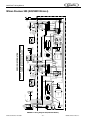
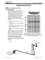
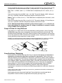
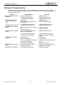
1
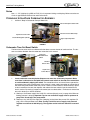
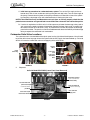
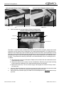
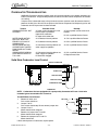
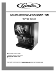
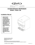
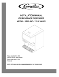
®
INTELLICARB
Training Manual
Release Date: April 29, 2004
Publication Number: TP01071
Revision Date: NA
Revision: A
Visit the IMI Cornelius web site at www.cornelius.com for all your Literature needs.
INTELLICARB TRAINING MANUAL
The products, technical information, and instructions contained in this manual are subject
to change without notice. These instructions are not intended to cover all details or variations of the equipment, nor to provide for every possible contingency in the installation,
operation or maintenance of this equipment. This manual assumes that the person(s)
working on the equipment have been trained and are skilled in working with electrical,
plumbing, pneumatic, and mechanical equipment. It is assumed that appropriate safety
precautions are taken and that all local safety and construction requirements are being
met, in addition to the information contained in this manual.
To inquire about current revisions of this and other documentation or for assistance with
any Cornelius product contact:
www.cornelius.com
800-238-3600
Trademarks and copyrights:
Aurora, Cornelius, Decade, Hydro Boost, Sitco, Spirit, UF-1, Vanguard, Venture, Olympus,
and Vista are registered trademarks of IMI Cornelius Inc.
Optifill trademark is pending.
This document contains proprietary information and it may not be
reproduced in any way without permission from Cornelius.
Printed in U.S.A.
Copyright © 2004, All Rights Reserved, IMI Cornelius Inc.
InelliCarb Training Manual
TABLE OF CONTENTS
Introduction . . . . . . . . . . . . . . . . . . . . . . . . . . . . . . . . . . . . . . . . . . . . . . . . . . . . . . . . . . .1
Unit Description . . . . . . . . . . . . . . . . . . . . . . . . . . . . . . . . . . . . . . . . . . . . . . . . . . . . . .1
Theory of Operation . . . . . . . . . . . . . . . . . . . . . . . . . . . . . . . . . . . . . . . . . . . . . . . . . .1
Description . . . . . . . . . . . . . . . . . . . . . . . . . . . . . . . . . . . . . . . . . . . . . . . . . . . . . . . . .1
Specifications . . . . . . . . . . . . . . . . . . . . . . . . . . . . . . . . . . . . . . . . . . . . . . . . . . . . . . .2
Requirements . . . . . . . . . . . . . . . . . . . . . . . . . . . . . . . . . . . . . . . . . . . . . . . . . . . . . . .2
Delivery Inspection and Unpacking . . . . . . . . . . . . . . . . . . . . . . . . . . . . . . . . . . . . . . .2
Installation . . . . . . . . . . . . . . . . . . . . . . . . . . . . . . . . . . . . . . . . . . . . . . . . . . . . . . . . . .3
Drains . . . . . . . . . . . . . . . . . . . . . . . . . . . . . . . . . . . . . . . . . . . . . . . . . . . . . . . . . .4
Cornelius IntelliCarb Carbonator Assembly . . . . . . . . . . . . . . . . . . . . . . . . . . . . . . . .4
Carbonator Time Out Reset Switch . . . . . . . . . . . . . . . . . . . . . . . . . . . . . . . . . . .4
Carbonator Relief Valve Locations . . . . . . . . . . . . . . . . . . . . . . . . . . . . . . . . . . . .5
Mechanical Section . . . . . . . . . . . . . . . . . . . . . . . . . . . . . . . . . . . . . . . . . . . . . . . . . . . . .8
Gate Restrictor Plate . . . . . . . . . . . . . . . . . . . . . . . . . . . . . . . . . . . . . . . . . . . . . . . . . .8
Adjustment . . . . . . . . . . . . . . . . . . . . . . . . . . . . . . . . . . . . . . . . . . . . . . . . . . . . . .8
Ice Diverter Kit 02394 . . . . . . . . . . . . . . . . . . . . . . . . . . . . . . . . . . . . . . . . . . . . . . . . .9
Removal and Replacement of Agitators . . . . . . . . . . . . . . . . . . . . . . . . . . . . . . . . . .10
To Remove Agitators For Cleaning (300 shown) . . . . . . . . . . . . . . . . . . . . . . . .10
Post-Mix Valve Section . . . . . . . . . . . . . . . . . . . . . . . . . . . . . . . . . . . . . . . . . . . . . . . . .11
Set-up Instructions . . . . . . . . . . . . . . . . . . . . . . . . . . . . . . . . . . . . . . . . . . . . . . . . . .11
Dimensions & Capacities . . . . . . . . . . . . . . . . . . . . . . . . . . . . . . . . . . . . . . . . . .11
System Details . . . . . . . . . . . . . . . . . . . . . . . . . . . . . . . . . . . . . . . . . . . . . . . . . . . . .11
Water . . . . . . . . . . . . . . . . . . . . . . . . . . . . . . . . . . . . . . . . . . . . . . . . . . . . . . . . . .11
Water Quality . . . . . . . . . . . . . . . . . . . . . . . . . . . . . . . . . . . . . . . . . . . . . . . .11
Water Flow . . . . . . . . . . . . . . . . . . . . . . . . . . . . . . . . . . . . . . . . . . . . . . . . . .11
Adjusting Flow Rates . . . . . . . . . . . . . . . . . . . . . . . . . . . . . . . . . . . . . . . . . .13
Calculating Flow Rates . . . . . . . . . . . . . . . . . . . . . . . . . . . . . . . . . . . . . . . . .13
Syrup/Concentrate . . . . . . . . . . . . . . . . . . . . . . . . . . . . . . . . . . . . . . . . . . . . . . .13
Setting Ratios . . . . . . . . . . . . . . . . . . . . . . . . . . . . . . . . . . . . . . . . . . . . . . . . . . .14
Shurflo . . . . . . . . . . . . . . . . . . . . . . . . . . . . . . . . . . . . . . . . . . . . . . . . . . . . . . . . . . . . . .15
Shurflow Overview . . . . . . . . . . . . . . . . . . . . . . . . . . . . . . . . . . . . . . . . . . . . . . . . . .15
Shurflow Installation . . . . . . . . . . . . . . . . . . . . . . . . . . . . . . . . . . . . . . . . . . . . . . . . .16
Start-up Procedure . . . . . . . . . . . . . . . . . . . . . . . . . . . . . . . . . . . . . . . . . . . . . . . . . .16
Plumbing . . . . . . . . . . . . . . . . . . . . . . . . . . . . . . . . . . . . . . . . . . . . . . . . . . . . . . . . . . . .17
Typical Installation . . . . . . . . . . . . . . . . . . . . . . . . . . . . . . . . . . . . . . . . . . . . . . . . . .17
Plumbing Layout . . . . . . . . . . . . . . . . . . . . . . . . . . . . . . . . . . . . . . . . . . . . . . . . . . . .18
Flow Diagram 1xx (Six Flavor Model) . . . . . . . . . . . . . . . . . . . . . . . . . . . . . . . . . . . .19
Flow Diagram 1XX (Eight Flavor Models) . . . . . . . . . . . . . . . . . . . . . . . . . . . . . . . . .20
Flow Diagram 2xx (Eight Flavor Models) . . . . . . . . . . . . . . . . . . . . . . . . . . . . . . . . .21
Flow Diagram 2xx (Ten Flavor Models)) . . . . . . . . . . . . . . . . . . . . . . . . . . . . . . . . . .22
Flow Diagram 300 (Twelve Flavor Models) . . . . . . . . . . . . . . . . . . . . . . . . . . . . . . .23
© 2004, IMI Cornelius Inc.
-i-
Publication Number: TP01071
IntelliCarb Training Manual
Electrical Section . . . . . . . . . . . . . . . . . . . . . . . . . . . . . . . . . . . . . . . . . . . . . . . . . . . . . 24
Carbonator Wiring Diagram . . . . . . . . . . . . . . . . . . . . . . . . . . . . . . . . . . . . . . . . . . . 25
Wiring Diagram 1xx (120V) . . . . . . . . . . . . . . . . . . . . . . . . . . . . . . . . . . . . . . . . . . . 26
Schematic 1xx . . . . . . . . . . . . . . . . . . . . . . . . . . . . . . . . . . . . . . . . . . . . . . . . . . . . . 27
Wiring Diagram 2xx (120V Model) . . . . . . . . . . . . . . . . . . . . . . . . . . . . . . . . . . . . . . 28
Wiring Diagram 2xx (220/240V Models) . . . . . . . . . . . . . . . . . . . . . . . . . . . . . . . . . . 29
Wiring Diagram 2xx (220/240V Models) . . . . . . . . . . . . . . . . . . . . . . . . . . . . . . . . . . 30
Wiring Diagram 300 (220/240V Models) . . . . . . . . . . . . . . . . . . . . . . . . . . . . . . . . . 31
Wiring Diagram 300 (220/240V Models) . . . . . . . . . . . . . . . . . . . . . . . . . . . . . . . . . 32
Schematic 300 (120V Models) . . . . . . . . . . . . . . . . . . . . . . . . . . . . . . . . . . . . . . . . . 33
Schematic 300 (220/240V Models) . . . . . . . . . . . . . . . . . . . . . . . . . . . . . . . . . . . . . 34
Troubleshooting . . . . . . . . . . . . . . . . . . . . . . . . . . . . . . . . . . . . . . . . . . . . . . . . . . . . . . 35
SHURflow Troubleshooting . . . . . . . . . . . . . . . . . . . . . . . . . . . . . . . . . . . . . . . . . . . 35
Pumping Capability . . . . . . . . . . . . . . . . . . . . . . . . . . . . . . . . . . . . . . . . . . . . . . . 35
Pumps in Series for Long Distances . . . . . . . . . . . . . . . . . . . . . . . . . . . . . . . . . 36
Pump Sanitizing / Winterizing . . . . . . . . . . . . . . . . . . . . . . . . . . . . . . . . . . . . . . . 36
Pump Troubleshooting . . . . . . . . . . . . . . . . . . . . . . . . . . . . . . . . . . . . . . . . . . . . 37
DOES NOT OPERATE / GAS APPLIED / DISPENSER VALVE OPEN . . . 37
OPERATES BUT WILL NOT PRIME / DISPENSER VALVE OPEN . . . . . . 37
DOES NOT ACHIEVE SOLD-OUT WITH EMPTY B-I-B . . . . . . . . . . . . . . . 37
AIR IN INLET AND/OR OUTLET TUBING . . . . . . . . . . . . . . . . . . . . . . . . . . 37
STROKES WITH DISPENSER VALVE CLOSED . . . . . . . . . . . . . . . . . . . . 37
FLUID FROM EXHAUST OR VISIBLE WITHIN GAS INLET TUBING . . . . . 37
GAS BLOWING FROM EXHAUST CONTINUOUSLY . . . . . . . . . . . . . . . . . 37
Dispenser Troubleshooting . . . . . . . . . . . . . . . . . . . . . . . . . . . . . . . . . . . . . . . . . . . 38
Valve Troubleshooting . . . . . . . . . . . . . . . . . . . . . . . . . . . . . . . . . . . . . . . . . . . . . . . 39
Excess Foam . . . . . . . . . . . . . . . . . . . . . . . . . . . . . . . . . . . . . . . . . . . . . . . . . . . 39
Off Taste . . . . . . . . . . . . . . . . . . . . . . . . . . . . . . . . . . . . . . . . . . . . . . . . . . . . . . . 40
Valve Stuck Open . . . . . . . . . . . . . . . . . . . . . . . . . . . . . . . . . . . . . . . . . . . . . . . . 41
No Product . . . . . . . . . . . . . . . . . . . . . . . . . . . . . . . . . . . . . . . . . . . . . . . . . . . . . 42
Carbonator Troubleshooting . . . . . . . . . . . . . . . . . . . . . . . . . . . . . . . . . . . . . . . . . . . 43
Solid State Carbonator Level Control . . . . . . . . . . . . . . . . . . . . . . . . . . . . . . . . . 43
Test Solid State Level Control . . . . . . . . . . . . . . . . . . . . . . . . . . . . . . . . . . . 43
Publication Number: TP01071
- ii -
© 2004, IMI Cornelius Inc.
InelliCarb Training Manual
INTRODUCTION
UNIT DESCRIPTION
•
Built-in cold carbonator produces bottle-quality drinks every time
•
No seasonal CO2 adjustments required for changes in water temperature
•
A complete system for simplified installation
•
Reduces service frequency and lowers equipment life cost
•
Generates increased beverage sales and greater consumer satisfaction
•
Illuminated merchandiser delivers unique, high impact marketing message
•
Ice used to cool cold plate kept separate from ice dispensed into cups
•
One piece ABS thermoformed plastic ice storage hopper. Durabide™ design provides durability and
ensures all ice in the hopper is dispensable
•
Unit readily accepts top mount cubers with manual ice fill capability
THEORY OF OPERATION
The rate of CO2 solubility increases with cold water. IntelliCarb System provides pre–chilled cold water
from the cold plate and mix with CO2 in the carbonator tank. The water is introduced into the tank with a
high volume 125gph Procon pump and high torque motor.
The amount of carbonated water reserve is controlled by a probe mounted in the tank. The probe is
called a “liquid level probe”. The liquid level probe senses the water level in the tank. Probe controls the
pump “ON” and “OFF” cycle through the electronic board called “liquid level board”.
NOTE: The probe works on a 5 M.V. D.C. current that continually reverses direction to prevent
probe corrosion.
DESCRIPTION
The “Enduro IntelliCarb” series of ice dispensers solves your ice and beverage service needs in a
sanitary, space saving, economical way. Designed to be automatically filled with ice from a top mounted
ice machine or manually filled with ice from any remote ice-making source, these dispensers will
dispense cubes (up to 1-1/4 inch in size), cubelets, and hard-chipped or cracked ice. In addition, the units
include beverage faucets, a cold plate, an internal carbonator tank and an external pump for the
carbonator, and are designed to be supplied direct from syrup tanks with no additional cooling required.
IMPORTANT: For dispensing compressed or extruded style ice, an Ice Diverter Kit must be installed on
the dispenser, see FIGURE 13 on page 9.
© 2004, IMI Cornelius Inc.
-1-
Publication Number: TP01071
IntelliCarb Training Manual
SPECIFICATIONS
Model
Descriptions:
Ice Storage:
Maximum
Number of
Faucets
Available:
Built-in Cold
Plate:
ED150
B=(Beverage)
C=(Coldplate)
H=(Internal
Carb)
Z=(No DripTray)
150 Pounds
6
ED175
B=(Beverage)
C=(Coldplate)
H=(Internal
Carb)
Z=(No DripTray)
175 Pounds
8
ED200
B=(Beverage)
C=(Coldplate)
H=(Internal
Carb)
Z=(No DripTray)
200 Pounds
10
ED250
B=(Beverage)
C=(Coldplate)
H=(Internal
Carb)
Z=(No DripTray)
250 Pounds
10
ED300
B=(Beverage)
C=(Coldplate)
H=(Internal
Carb)
Z=(No DripTray)
300 Pounds
12
Yes
Yes
Yes
Yes
Yes
$PSV7RWDO8QLW'UDZ
120/1/60, 3.5 Amps Total Unit Draw
230/1/50, 2.0 Amps Total Unit Draw
Electrical:
Width 22”
Deep 30--11/16”
High 35--5/8”
Dimensions:
Outlet should be within 6 feet of dispenser.
Width 24.5”
Width 22”
Width 24.5”
Deep 30–11/16”
Deep 30--11/16” Deep 30–11/16”
High 39–5/8”
High 35–5/8”
High 35--5/8”
Width 22”
Deep 23--1/16”
High 35--5/8”
CO2 Operating 75--psig (max)
Pressure
Width 24--1/2”
Deep 23--1/16”
High 35--5/8”
75--psig (max)
Width 22”
Deep 23–1/16”
High 35–5/8”
75–psig (max)
Width 44–3/8”
Deep 31–1/2”
High 37”
Z–Models
Z–Models
Z--Models
120/1/60, 4.0
Amps Total Unit
Draw
230/1/50, 3.0
Amps Total Unit
Draw
Width 24–1/2”
Deep 23–1/16”
High 39–5/8”
75–psig (max)
Width 44–3/8”
Deep 23–1/16”
High 37”
75–psig (max)
REQUIREMENTS
•
Weight: counter must be level and able to support 450 lbs.
•
Environment: Indoor installation only
•
Temperature: 40 to 100oF
•
CO2: 75 psi at unit
•
Syrup: 60 psi., 0.70 -- 0.75 ounces per sec. (0.6 gpm) at unit
•
Water: 60 psi at pump
•
Electrical: See name plate
DELIVERY INSPECTION AND UNPACKING
Upon delivery inspect the unit for damage or irregularities and immediately report problems to the
delivering carrier and file a claim with that carrier.
•
Open loose parts packages and inspect parts.
Part No.
710000030
70970
70750
620702201
51774
50335
Publication Number: TP01071
Description
Pump and Motor Assy
4”Legs
Clamps
Brush
Drain Pan Drain Line
Drain Line Insulation
)LWWLQJ6RF[)SW
)LWWLQJ0SW[µ%DUE
-2-
Qty.
1
4
2
1
1
1
1
1
© 2004, IMI Cornelius Inc.
InelliCarb Training Manual
INSTALLATION
1.
Locate the dispenser indoors on a level counter top.
A. LEG OPTION
Unpack the four (4) legs and install them into the threaded holes provided in the bottom of the
unit. The installer must provide flexibility in the product and utility supply to permit shifting the
position of the dispenser sufficiently to clean the area beneath it.
B. COUNTER MOUNTING
If counter mounted the ice drink dispenser must be sealed to the counter. The template drawing
indicates where openings can be cut in the counter. Locate the desired position for the dispenser,
then mark the outline dimensions on the counter using the template drawings. Cut openings in
counter.
Apply a continuous bead of NSF International (NSF) silastic sealant (Dow 732 or equal) approximately 1/4--inch inside of the unit outline dimensions and around all openings. Then, position the
unit on the counter within the outline dimensions. All excess sealant must be wiped away immediately.
2. The beverage tubes, drain tube and power cord are routed through the large opening in the bottom
of the unit. See the mounting template for locating the required clearance opening in the counter for
these utility lines.
3. Drip tray assembly: Route the drain tube to an open drain with the end of the tube above the “flood”
level of the drain. Use the tubing, fittings, clamps, and insulation provided with the Dispenser to
assemble the drain. The completed drain line must pitch continuously downward and contain no
“traps” or improper drainage will result. Must have a 4 inch air gap between drain line and drain.
NOTE: This equipment must be installed with adequate backflow protection to comply with federal, state, and local codes.
NOTE: IMI Cornelius Inc. recommends that a water shutoff valve and water filter be installed in
the plain water inlet supply line. A Cornelius Water Filter (P/N 313860000) and QUICK DISCONNECT SET (P/N 313867000) are recommended.
CAUTION: Check the minimum flow rate and the maximum pressure of the plain water inlet supply line.
MINUMUM FLOW RATE MUST BE AT LEAST 125--GALLONS PER HOUR. If flow rate is less than 125-gallons per hour, starving of the carbonator water pump will occur. Starving will damage the water pump
and could cause the carbonator to time out. INCOMING PLAIN WATER INLET SUPPLY LINE WATER
TO PUMP PRESSURE MUST REMAIN A MINIMUM OF 10--PSI BELOW THE CARBONATOR CO2
OPERATING PRESSURE. (Example: Carbonator CO2 operating pressure is 75--PSI and the maximum
water pressure can be no more than 65--psi, etc.). Water over pressure (higher than CO2 operating pressure) can cause carbonator flooding, malfunction, and leakage through the carbonator relief valve. If
water is exceeding maximum pressure specifications, a Water Pressure Regulator Kit (P/N 310150000)
or equivalent must be installed in the plain water inlet supply line. If fitting connector is not available,
water line must be 1/2” or 3/4” diameter with a shut off valve within 6 feet of the dispenser.
4.
Locate the carbonator pump assembly and connect probe wires from Ice/Drink Unit and pump. Connect inlet water to pump and pump outlet to Ice/Drink Unit using 3/8--inch food--grade tubing.
NOTE: Locate carbonator assembly within 6 feet of the dispenser. Do not lengthen the control
board harness.
5. Connect the beverage system product tubes as indicated in applicable Plumbing Flow Diagram, see
page 19. This work should be done by a qualified service person.
NOTE: Water pressure for non carbonated beverages must be 60 P.S.I. minimum.
NOTE: See applicable Flow Diagram or Decal on the lower front of the unit for the location of
syrup and water connections.
6.
7.
Clean the hopper interior.
Connect the two power cords to a 120 volt, 60 cycle, 3-wire grounded receptacle. For 220--240 Volt
International Units, a 3--wire power cord is provided. An adapter plug for the particular country will
need to be provided by the Installer.
© 2004, IMI Cornelius Inc.
-3-
Publication Number: TP01071
IntelliCarb Training Manual
Drains
Use a 1 - 1/2” rigid pipe (e.g. ABS on P.V.C.) this is to prevent kinking or collapsing. Make sure to leave a
4 inch air gap between the drain line and the floor drain.
CORNELIUS INTELLICARB CARBONATOR ASSEMBLY
1.
Ice Drink / Drop-In Carbonator Pump & Motor Unit
Vent to Atmosphere Check Valve
125 G.P.H. ProCon Water Pump
Liquid Level Control Box
Preset CO2 Regulator (75P.S.I.)
High Torque Pump Motor
FIGURE 1
Carbonator Time Out Reset Switch
The board can be set to turn the carbonator off after three or seven minutes of continuos time. The feature can also be disabled. See the carbonator instruction in this manual.
Carbonator
Time Out Reset
Switch
Time Out
Selector Pins
Liquid Level
Control Board
FIGURE 2
1.
FIGURE 3
Locate carbonator assembly below dispenser no more than 6 feet away. Important: Make
sure there is clearance for the liquid level control reset switch on the side of the control box
to avoid accidentally tripping the switch. The control board has an internal timer to prevent the
pump motor from running continuously. In the event of a water supply interruption or malfunction of
the water level probe and/or motor relay circuit. If there is a time-out event, make necessary repairs
to what caused the time out, then depress and release the reset switch to put the control board
back in service. By moving a jumper on the control you can select either a 7 minute or 3 minute time
out or this feature can also be disabled.
A. Hook-up a 3/8 ID water supply line 125 G.P.H. minimum (60 psig. max.) to pump inlet. Minimum
flowing pressure is 30 psig. Important: Tap for non-carb water supply must be upstream of
pump inlet. Do not tap in the pump outlet.
B. Hook-up a 3/8 (.375 ID) CO2 supply line (100 psig.) to the inlet of the pre-set CO2 regulator (75
psig.) on the Pump & Motor base. Note: If using a bulk CO2 tank as supply, tank pressure
regulator must be set to 100-105 psig. The regulator on the bulk tank should be a secondary.
Publication Number: TP01071
-4-
© 2004, IMI Cornelius Inc.
InelliCarb Training Manual
C. Initial start-up procedure for carbonated water system: Turn on the CO2 supply to the carbonator tank, vent air from carbonator tank by pulling the tank relief valve. Turn on water supply to
the pump. Connect electrical power to the pump and motor unit. Bleed the air out of the system
by energizing a beverage valve until carbonated water is flowing from the valve.
NOTE:If the carbonator Pump and Motor does not cycle (turn on and off) properly, check that the
probe harness connector and ground lead are secured to the carbonator tank connection points.
D. If service is required on Ice Drink units, it will be necessary to lower the beverage valve panel to
gain access to the probe and ground connection. Remove the lower front panel (2 screws) from
the cabinet and the ice chute cover (“snap” fit). Remove the 6 screws that secure the beverage
panel to the cabinet. The panel can now be moved downward due to the flexibility of the beverage
tubing to expose the carbonator tank connections.
Carbonator Relief Valve Locations
The carbonator tank is located behind the splash panel, on the right side of the dispenser. You will need
to pull the relief valves to purge air from the system after the CO2 supply has been hooked up. Failure to
do this will cause low carbonation volume and popping of the relief valves.
Agitator
Motor
Relief
Valve Ring
Carbonator
Tank
Carbonator
Tank Relief
Valve
FIGURE 7
FIGURE 6
2.
Dispenser
Ice Drink Model ED175BCH (Lower Front Panel Removed)
Insulated Cold Plate
Cover & Carbonator
Tank Assembly
Total Flex Manifold
(with insulation)
Total Flex Manifold
(insulation removed)
Cold Plate Inlets
(3/8 Barb)
Carb Tank CO2
Supply Line
Carb. Tank Liquid
Level Probe Harness
FIGURE 8
© 2004, IMI Cornelius Inc.
-5-
Publication Number: TP01071
IntelliCarb Training Manual
Ice Drink Model ED150/175/300 Coldplate Cover
Liquid Level Probe
Ice Drink Model ED200/250 Coldplate Cover
CO2 Check Valve with Ground Stud
In-line CO2 Check Valve
3.
Ground Plate/Stud
Probe
FIGURE 10
FIGURE 9
Total Flex System for Ice Drink Models ED150/175/200/250/300
Total Flex Manifold (Insulation Removed)
Water Line
Plugs
Retainer Clip
Manifold Block
FIGURE 11
Total Flex is a system of water manifold blocks located at the front of the cold plate, adjacent to the cold
plate inlets, for easy switch over of carbonated / non-carbonated beverage drinks. The right hand manifold block is for the beverage valves located to the right side of the ice chute, and the left block is for the
left bank of valves. Each beverage valve on the dispenser can be set up for either carbonated or non-carbonated drinks. Refer to the unit’s plumbing diagram for the factory carbonated / non-carbonated valve
locations. The procedure for switching carbonated / non-carbonated water lines on a beverage valve is
as follows:
A. Shut off the water supply to the dispenser. Depressurize and drain both the carbonated and noncarbonated water circuits.
B. Remove the retainer clip (2 screws) from the manifold block. Switch the plug and water line fitting
to their respective carbonated / non-carbonated outlet locations on the block.
C. Replace the retainer clip. Turn on the water supply and energize the “switched” valve(s). Check
for water leaks.
4.
5.
Important: Route the dispenser’s drain line to an open drain with the end of the tube above the flood
level of the drain. The drain line must pitch downward and contain no “traps”.
Connect both the carbonator pump and motor unit and the dispenser to a grounded electrical supply outlet.
Publication Number: TP01071
-6-
© 2004, IMI Cornelius Inc.
IntelliCarb Training Manual
6.
Check list for proper “finished” drink carbonation:
A. Fill ice storage hopper with ice.
B. Water supply must be from a continuous source (no tank supply).
C. Use only filtered water.
D. Supply water line to the carbonator pump must be a minimum of .375 ID.
E. Syrup supply lines must be a minimum of .265 ID.
F. Water inlet pressure range: 45-60 max. static psig. with a minimum flowing pressure of 30 psig.
G. Syrup CO2 secondary regulator pressure set to 60 psig.
H. CO2 supply must be high quality, food grade.
I. Purge all water, carb-water, and product lines of air before brixing valves.
J. Important: Brix valves with cold product. Allow at least 15-20 minutes for ice to cool down the
coldplate on initial start-up before brixing the valves.
K. Dispense at least (2) 12 oz. drinks before taking a carbonation level reading.
L. Carbonation tester thermometer must read 32-33oF. for accurate carb-level reading. Store tester
in ice water bath during use.
M. Hold cup at valve nozzle for drink to be tested. Pour drink slowly down the side wall into the carbtester to avoid agitation during pouring. Press vent valve once on carb-tester after tightening lid.
N. Shake carb-tester in vertical motion until peak pressure reading is obtained. Use Pepsi chart for
carbonation level reading.
NOTE: Carbonator troubleshooting procedure located on page 43.
© 2004, IMI Cornelius Inc.
-7-
Publication Number: TP01071
IntelliCarb Training Manual
MECHANICAL SECTION
GATE RESTRICTOR PLATE
NOTE: Disconnect power to dispenser before installing, removing, or adjusting restrictor.
ADJUSTMENT
INSTALL PLATE
ON STUDS AS
SHOWN
FIGURE 12
Adjustment
This plate may be adjusted as shown to reduce or increase the dispensing rate of ice, especially
desirable when using glasses or other containers with small openings. Adjustment can be made by
sliding up or down with nuts loosened, to obtain the desired amount of restriction.
Publication Number: TP01071
-8-
© 2004, IMI Cornelius Inc.
IntelliCarb Training Manual
ICE DIVERTER KIT 02394
NOTE: For dispensing Scotsman, Wilshire, and Hoshizaki compressed ice cubes:
1.
2.
3.
4.
5.
6.
7.
Disconnect power to dispenser.
Remove Merchandiser from dispenser.
Remove ice chute and discard gate restrictor.
Install ice diverter on gate mounting plate as shown below.
Apply RTV to back surface of ice diverter, to seal to gate mounting plate.
Reinstall gasket and ice chute.
Reinstall merchandiser and energize unit.
G AT E MOUNT ING P L AT E
S TOR A G E HOP P E R
F L A NG E E XT E NDS
INTO S TOR A G E HOP P E R T HR OUG H G AT E
OP E NING
IC E DIV E R T E R
IC E C HUT E
C OV E R
A P P LY R T V TO
T HIS S UR FA C E TO
S E A L TO HOP P E R
G AT E MOUNT ING
10-- 32 WA S HE R
GAS K E T
P L AT E
IC E C HUT E
10-- 32 NUT
FIGURE 13
© 2004, IMI Cornelius Inc.
-9-
Publication Number: TP01071
IntelliCarb Training Manual
REMOVAL AND REPLACEMENT OF AGITATORS
To Remove Agitators For Cleaning (300 shown)
NOTE: All other models have only one agitation Assembly.
RIGHT HAND AGITATOR
WITH HOLE IN UPRIGHT
LEFT HAND
AGITATOR
O–RING
COUNTERCLOCKWISE
CLOCKWISE
ROTATION
ROTATION
FRONT (VALVE SIDE) VIEW FROM TOP OF DISPENSER
FIGURE 14
1. Lift agitator and disc from unit.
2. Remove O-Ring starting at notch. Warm the O-Ring with water to ease removal.
3. Lift the plastic agitator disc off of the stainless-steel agitator.
4. Replace by reversing steps.
NOTE: Refer to Sanitize Procedure in the Owners Instruction for complete cleaning and sanitizing instructions.
Publication Number: TP01071
- 10 -
© 2004, IMI Cornelius Inc.
IntelliCarb Training Manual
POST-MIX VALVE SECTION
SET-UP INSTRUCTIONS
Concentrate valve sleeve
has only one hole
Syrup valve sleeve
has six holes
FIGURE 15
A side water lever kit can be added to a valve allowing for
dispensing of water without syrup or concentrate. The side
water lever can be added to either a carbonated drink valve
or a noncarbonated drink valve.
Post-mix valves control:
Mounting
screw
Water
lever
•
the ON–OFF of syrup and water,
•
the flow rates of syrup and water,
•
the mixing of the two ingredients as they pour into the
cup, and
•
in some instances - dispensed portion.
FIGURE 16
Dimensions & Capacities
Fast Flow ............................................................................................................... 1 ½ to 3 oz./sec.
UFB-1 ......................................................................................................................... 2 to 4 oz./sec.
Ultra Flow .............................................................................................................. 3 to 4 ½ oz./sec.
Operational temperature range: ......................................................... 10°C (50°F) to 43°C (110° F)
Voltage requirements:................................................................................ 22 to 27 VAC (50/60 Hz)
Transformer (electronic valves) ........................................................................................80 VA min.
Operating Pressure (flowing) ...............................................................................syrup = 20 psi min.
.............................................................................................................................water = 35 psi min.
Concentrates and juices that contain particulates must be dispensed from a juice valve.
A slanted drip tray is necessary when using an Optifill valve.
SYSTEM DETAILS
Water
Water Quality
Water quality issues have an affect on dispensing valves. Chloramine, a combination of chlorine and
ammonia is responsible for some degradation of rubber components. Chloramine is used in many U. S.
water supplies. Its affects can be minimized by installing and maintaining a water filtration system.
Ultra pure water affects the sensitivity of the Optifill™ valve. Because ultra pure water has less mineral
content, it reduces the conductivity of the water keeping the circuit open and overfilling the beverage
container.
Water Flow
The size of the orifice in the piston varies depending on whether the piston is used for syrup or water, and
whether it is high flow or ultra flow valve.
© 2004, IMI Cornelius Inc.
- 11 -
Publication Number: TP01071
IntelliCarb Training Manual
NOTE: The notched water piston on the Ultra Flow and UFB-1 valve.
results in at least one orifice in the sleeve always open. This eliminates pulsating and smooths water flow at higher flow rates.
In operation the liquid flows through the knife–edged orifice in the bottom
of the piston and then out the orifices in the sleeve. The outlet orifice size
in the sleeve is regulated by the position of the piston. In the illustration,
the piston is restricting approximately 1/2 of the outlet orifices.
Notch in
piston
FIGURE 17
UFB-1 Flow Module
Orifice
Sleeve
Piston
FIGURE 18
Lower Fluid Pressure BUT
Larger Orifice Openings
Higher Fluid Pressure BUT
Smaller Orifice Openings
Same Volume Of
Syrup/Water Flows
From Orifices
Knife
edge
Syrup/Water Flow
Higher Fluid
Pressure Pushing
Against Piston &
Spring
Lower Fluid
Pressure Pushing Against Piston & Spring
FIGURE 19
The position of the piston inside the sleeve is determined by the upward pressure of the liquid against the
base of the piston and the downward pressure of the spring inside the piston (not shown here). The
pressure of the spring is regulated by the adjusting screw.
If the pressure of the liquid increases, the flow rate through the knife–edged orifice will increase. The
piston is moved upward closing off more of the outlet orifices. The same flow rate is thereby maintained.
Publication Number: TP01071
- 12 -
© 2004, IMI Cornelius Inc.
IntelliCarb Training Manual
Adjusting Flow Rates
Flow rates of the water and syrup are adjusted based on the desired ratio. For example: if the desired
ratio is 5:1, then the flow rate of the water is 5 times that of the syrup.
If the desired finished drink total flow rate is 3.0 ounces per second, then the water flow rate is 2.5 oz./
sec and the syrup flow rate is 0.5 oz./sec. (The water at 2.5 oz./sec is five times the 0.5 oz./sec syrup flow
rate.)
NOTE: Always adjust water within its range.
Water Flow Rates At Selected Ratios
Water To Syrup
Ratio
Water at 1.5 oz./
sec. Total Flow
Water at 3.0 oz./
sec. Total Flow
Water at 3.75 oz./
sec. Total Flow
Water at 4.5 oz./
sec. Total Flow
2 to 1
1.00 oz./sec.
2.00 oz./sec.
2.50 oz./sec.
3.00 oz./sec.
3 to 1
1.13 oz./sec.
2.25 oz./sec.
2.81 oz./sec.
3.38 oz./sec.
4 to 1
1.20 oz./sec.
2.40 oz./sec.
3.00 oz./sec.
3.60 oz./sec.
5 to 1
1.25 oz./sec.
2.50 oz./sec.
3.13 oz./sec.
3.75 oz./sec.
6 to 1
1.29 oz./sec.
2.57 oz./sec.
3.21 oz./sec.
3.86 oz./sec.
7 to 1
1.31 oz./sec.
2.63 oz./sec.
3.28 oz./sec.
3.94 oz./sec.
Calculating Flow Rates
The most frequent ratio is 5:1. The charts above list the breakdown for many ratios and flow rates. It is
useful to be able to calculate flow rates when a chart is not available.
An example of calculating the water and syrup flow rates given the finished drink flow rate and the water
to syrup ratio:
Given:
1. Finished Drink Flow Rate = 3.0 oz./sec.
2. Water to Syrup Ratio = 5 to 1
To calculate Water Flow Rate:
1.
Calculate the Total Portions = Water Portion + Syrup Portion
(example 5 + 1 = 6)
2. Calculate Syrup Flow Rate = Finished Drink Flow Rate ÷ Total Portions
(example 3.0 oz./sec ÷ 6 = .5 oz./sec)
3. Calculate Water Flow Rate = Finished Drink Flow Rate – Syrup Flow Rate
(example 3.0 oz./sec - .5 oz./sec = 2.5 oz./sec)
Prove the calculation is correct by adding water flow rate of 2.5 oz./sec + syrup flow rate of .5 oz./sec =
finished drink flow rate of 3.0 oz./sec.
Water flowing at 2.5 oz./sec and syrup flowing at .5 oz./sec achieves a ratio of 5:1 and 3.0 oz./sec. flow
rate.
Syrup/Concentrate
Syrup should always be precooled before setting the ratio. Syrup takes a path through the valve
parallel to the water path. It is introduced in the block, travels through a syrup flow control, banjo, valve
head and out the nozzle. Note, concentrate is not cooled.
High sugar syrups are more viscous (thicker) than diet syrups and consequently have more
pressure drop within a system. This pressure drop results in less flow at the valve and therefore a slower
fill time. Increasing the pump pressure will help overcome the pressure drop caused by high sugar
syrups.
© 2004, IMI Cornelius Inc.
- 13 -
Publication Number: TP01071
IntelliCarb Training Manual
Setting Ratios
If the ratio varies and must be adjusted often, it is probably the result of a restricted syrup
system. It is then time to clean and sanitize the syrup tubing and cooling coils and check for other
problems such as syrup pumps, etc.
NOTE: Try raising the pressure on the pump before cleaning.
Set the water flow rate first, then adjust the syrup to the desired ratio. This gives the most accurate
valve flow setting possible. Measure the ratio and adjust the syrup flow, if necessary. This will result in
uniform flow, better carbonation retention, and improved drink quality.
When using a ratio cup always take these precautions to ensure accuracy:
•
After installing the separator tube, open the valve to fill the syrup tube before starting the ratio test.
•
Clean the cup thoroughly between tests so there is no carry–over from one test to the next.
•
Fill the cup to approximately 3/4 full and use approximately the same quantity for each test to ensure
accurate settings.
•
Take another sample to verify the settings.
Ratio Cup and Syrup Separator
FIGURE 20
NOTE: Valve troubleshooting information is available on page 39.
Publication Number: TP01071
- 14 -
© 2004, IMI Cornelius Inc.
IntelliCarb Training Manual
SHURFLO
SHURFLOW OVERVIEW
SHURflo’s Beverage Gas Pump supplies syrup under pressure to a post-mix dispenser, which mixes the
syrup with water to an exact ratio (brix). The pump is used in conjunction with non-pressurized Bag-InBox (B-I-B) containers and a bag connector (Q.D.) fitting.
The pump can be operated on regulated CO2, nitrogen or compressed filtered air. The compressed gas
drives the pump and is not in contact with the syrup. Separate syrup and gas chambers prevent
contamination, foaming, and purging of the tubing when the B-I-B has emptied.
The pump retains pressure in the outlet line, operating only when syrup is needed. When the dispenser
valve is opened, the pump reacts to the pressure drop by operating to maintain pressure in the line.
When the dispenser is closed, the incoming gas and output syrup pressures equalize and the pump
stops. Actual dynamic line pressure is dependant upon system losses as outlined in the section
"Pumping Capability".
The automatic "sold-out" feature within the pump ensures consistent syrup delivery right up to the
moment the B-I-B is empty. Vacuum produced by the pump evacuates the syrup within the bag. Once the
preset vacuum point is achieved and held, incoming gas pressure to the pump is shutoff causing the
outlet syrup pressure to drop to zero. When a new B-I-B is installed, the vacuum drops, the pump
automatically restarts and pressurizes the system. The SHURflo Beverage Gas Pump ensures quality
from the first drink to the last.
Beverage Gas Pumps are intended for soda syrups and low viscosity concentrates that do not contain
solids.
The use of a SHURflo Juice Pump (-09) is recommended for concentrates containing soft solids, classed
as round, up to 0.025 in. [0.6 mm] or that are of higher viscosity than soda syrups.
When concentrates contain pulp classed as long/stringy, seed particles or are exceptionally viscous, the
Particulate Juice Pump (-10) should be used as it can handle soft solids up to 1 /4" [6 mm] cubed.
Standard gas pump models are for installations where geographic elevation is less than 5000 ft.[1523M].
For elevations above 5000 ft. specific high altitude models with a reduced sold-out spring rate must be
used to compensate for the loss in atmosheric pressure.
For further application and model information please contact SHURflo.
NOTE: Shurflow Troubleshooting information available on page 35.
© 2004, IMI Cornelius Inc.
- 15 -
Publication Number: TP01071
IntelliCarb Training Manual
SHURFLOW INSTALLATION
•
As indicated on the pump, the outlet port is to be mounted up.
•
Pumps are to be mounted at the same level or higher than the B-I-B. The best choice is to have the
pump above the B-I-B.
•
INLET tubing from the B-I-B to the pump use; 3/8" I.D. [10mm] minimum, heavy wall (1/8"
[3mm]) clear, NSF listed vacuum tubing. Inlet tubing should not have excessive length. Tub-
ing that is allowed to drape down can trap air in the B-I-B creating a potential for pump "soldout" problems. The maximum vertical distance from the bottom of the B-I-B to the pump must
not exceed 5 ft [1.5 M ]. Maximum inlet tubing length is 10 ft. [3 M ].
•
If plumbing multiple B-I-B’s to a pump, B-I-B's should be "Teed" side-by-side horizontally,
rather than one on top of the other (vertically).
•
OUTLET tubing from the pump to the dispenser should be high pressure rated and NSF
listed. Consult "Pumping Capability" (see page 2) for appropiate tubing I.D.
•
Always cut CO2 and outlet tubing at least 2 ft. [.6 M] longer to provide a "service loop" so the
B-I-B rack can be moved for cleaning or service.
•
Use new (clean), 1/4" I.D. [6 mm], flexible, high pressure, braided tubing from the CO2 / air
regulator to the pump.
NEVER connect a transfer tank "system" in series with a B-I-B system. Syrup contaminants in
old components may work their way through the air supply causing premature failure of the gas
pump. Gas used to operate pumps MUST be clean and contain no contaminants (syrup, oil, rust,
water, etc). Air compressors may be used with proper particle filters and moisture separators. Air storage
tanks should be drained regularly. Pumps subjected to contaminated air are not covered by warranty.
High concentrations of CO2 can be fatal as it will displace the air from non-ventilated areas.
Pumps operated by CO2 must be in ventilated areas.
If placed in a confined area (basement, closet, cooler box, etc.), exhaust fans capable of changing
the room air on a continuous basis should be used.
•
All tubing connections must be secured with stainless steel, stepless Oetiker ® clamps.
•
Cable-tie all tubing securely to prevent kinks or sags that inhibit performance or cause damage to the
pump fittings.
START-UP PROCEDURE
1.
2.
3.
4.
Confirm that all tubing connections are properly clamped, fittings are tight, and tubing is not kinked.
Install bag connector to the B-I-B.
Adjust gas regulator to about 20 psi. [1.4 bar] allowing the pump to stroke slowly.
Operate the valve until all air trapped within the tubing has been purged.
Once the air has been purged, adjust the CO2 regulator to the pressure necessary to maintain the desired brix. The most efficient gas usage occurs at 40 psi. [2.8 bar]. MAXIMUM
static gas pressure to the pump is 85 psi. [5.8 bar], minimum 20 psi. [1.4 bar].
Flowrates that result in a stroke-rate of more than two strokes per second will decrease pump
life. (Consult factory) Pump failure due to "overrunning" is not covered by the limited warranty.
To prevent air from entering the system always leave the bag connector attached to the empty
B-I-B until a new B-I-B can be installed. Air entered into the system, via air in the bags or
vacuum leaks, may cause brix fluctuation, foaming, spitting, non-operation of the vacuum soldout or pump "run-on" with the valve closed. Symptoms of this kind can lead to a misdiagnosis of the
pump.
Publication Number: TP01071
- 16 -
© 2004, IMI Cornelius Inc.
IntelliCarb Training Manual
PLUMBING
TYPICAL INSTALLATION
FIGURE 21. Typical Installation
© 2004, IMI Cornelius Inc.
- 17 -
Publication Number: TP01071
IntelliCarb Training Manual
PLUMBING LAYOUT
Brand Syrup Inlets
3-5 Per Side
Carb Water In
Plain Water In
Carbonator Tank CO2 Inlet
Brand Syrup Inlets
3-5 Per Side
Connection Legend
B
B
B
C
B
75 psi Fixed Reg
Carb
Pump
B
3/8" Barb Conn
C
1/4" Barb Conn
D
3/8" Hose Barb - 3/4" NP
E
1/4" Female Flr Nut
F
Direct Conn to SUR
Outlet on BIB Pmp
G
Direct Conn to CO2
Inlet on BIB Pmp
H
Syr Inlet BIB Pmp
I
3/4" NPT TEE
CO2 Supply
Regulator
100 psi
E
A
3/8" Female Fir Nut
C
E
A
A
Regulator
55-60 psi
E
D
Water Filter
I
D
H
BIB Syrup
F
BIB Pump
G
F
BIB Pump
G
6-10 Brand
Flavors
BIB Syrup
H
Tubing Legend
3/8" Bev Tubing
1/4" Bev Tubing
3/8" Tycon Tubing
FIGURE 22. Plumbing Layout
Publication Number: TP01071
- 18 -
© 2004, IMI Cornelius Inc.
FAUCETS
W1,
VALVES 1,2,
3,6
W1
6
S6
OPTIONAL
PRESSURE
REGULATOR
POTABLE
WATER
SUPPLY
5
S5
FILTER
W2
4
CARBONATOR
PUMP
S4
COLDPLATE
NON-- CARB
WATER
INSTALL FOR
NON-- CARB AS
REQUIRED
CHECK
VALVE
S5
INLET
S6
CONNECTIONS
S7
S1
S2
CARBONATOR
TANK
FIGURE 23. Flow Diagram 1xx (Six Flavor Model)
- 19 -
FAUCETS VIEWED FROM THIS SIDE
W2,
VALVES 4,5
S3
W2
3
5-- 15
PSIG
OPTIONAL FOR
DIET DRINKS
OR ROOT BEER
PLUGGED
S3
FLOW DIAGRAM 1XX (SIX FLAVOR MODEL)
© 2004, IMI Cornelius Inc.
DOUBLE CHECK
VALVE
75 PSI
2
S2
W1
1
S1
COLD PLATE
S3
S2
S1
S7
SYRUP TANKS
15-- 50 PSIG
S6
S5
PRESSURE
REGULATORS
ITEMS INSIDE BROKEN LINE
INCLUDED WITH UNIT
IntelliCarb Training Manual
Publication Number: TP01071
CO2
CYLINDER
S8
W1
OPTIONAL
PRESSURE
REGULATOR
7
POTABLE
WATER
SUPPLY
S7
FILTER
6
W2
5
CARBONATOR
PUMP
W2,
VALVES 4,
5,6
S5
NON-- CARB
WATER
CHECK
VALVE
INSTALL FOR
NON-- CARB AS
REQUIRED
S5
S6
COLDPLATE
INLET
CONNECTIONS
S7
S8
S1
S2
CARBONATOR
TANK
FAUCETS VIEWED FROM THIS SIDE
- 20 -
FIGURE 24. Flow Diagram 1XX (Eight Flavor Models)
S6
S3
S4
4
S4
W2
5-- 15
PSIG
OPTIONAL FOR
DIET DRINKS
OR ROOT BEER
3
75 PSI
S3
2
S2
S4
W1
1
© 2004, IMI Cornelius Inc.
S1
S3
S2
S1
SYRUP TANKS
15-- 50 PSIG
S8
S7
S6
S5
PRESSURE
REGULATORS
COLD PLATE
CO2
CYLINDER
ITEMS INSIDE BROKEN LINE
INCLUDED WITH UNIT
IntelliCarb Training Manual
W1,
VALVES 1,2,
3,7,8
8
FLOW DIAGRAM 1XX (EIGHT FLAVOR MODELS)
Publication Number: TP01071
DOUBLE CHECK
VALVE
FAUCETS
8
W1
OPTIONAL
PRESSURE
REGULATOR
W1
VALVES 1,2
3,6,7,8
POTABLE
7
WATER
SUPPLY
FILTER
W2
VALVES 4,5
CARBONATOR
INSTALL FOR
6
NON–CARB AS
REQUIRED
W2
CHECK
VALVE
S8
Non–Carb Water
S7
S6
COLDPLATE
INLET
CONNECTIONS
S5
W2
W1
S4
CARBONATOR
TANK
- 21 -
FIGURE 25. Flow Diagram 2xx (Eight Flavor Models)
5
S3
S2
S1
4
OPTIONAL FOR
DIET DRINKS
OR ROOT BEER
W2
75 PSI
5–15
PSIG
3
FLOW DIAGRAM 2XX (EIGHT FLAVOR MODELS)
© 2004, IMI Cornelius Inc.
DOUBLE CHECK
VALVE
FAUCETS
2
W1
Publication Number: TP01071
S1
COLD PLATE
ITEMS INSIDE BROKEN LINE
INCLUDED WITH UNIT
S2
S3
S4
S5
SYRUP TANKS
15–50 PSIG
S6
S7
S8
PRESSURE
REGULATORS
CO2
Cylinder
IntelliCarb Training Manual
1
Publication Number: TP01071
- 22 -
1
2
3
4
5
CARBONATOR
TANK
S1
S2
S3
S4
S5
S6
S7
S8
S9
S10
COLD PLATE
W1
W2
W2
W1
ITEMS INSIDE BROKEN LINE
INCLUDED WITH UNIT
COLDPLATE
INLET
CONNECTIONS
6
7
8
9
10
FAUCETS
S1
S2
S3
S4
S5
S6
S7
S8
S9
S10
OPTIONAL FOR
DIET DRINKS
OR ROOT BEER
5–15
PSIG
W2
VALVES 5,6
W1
VALVES 1,2,3
4,7,8,9,10
S1
S2
S3
S5
SYRUP TANKS
15–50 PSIG
S4
S6
S7
CARBONATOR
PUMP
NON CARB WATER
DOUBLE CHECK
VALVE
S8
CHECK
VALVE
S9
75 PSI
CO2
CYLINDER
PRESSURE
REGULATORS
S10
INSTALL FOR
NON–CARB AS
REQUIRED
OPTIONAL
PRESSURE
REGULATOR
FILTER
POTABLE
WATER
SUPPLY
IntelliCarb Training Manual
FLOW DIAGRAM 2XX (TEN FLAVOR MODELS))
FAUCETS VIEWED FROM THIS SIDE
FIGURE 26. Flow Diagram 2xx (Ten Flavor Models)
© 2004, IMI Cornelius Inc.
12
DOUBLE CHECK
VALVE
COLD PLATE
W1
S12
OPTIONAL
PRESSURE
REGULATOR
11
S11
W2
FILTER
10
S10
COLDPLATE
INLET
CONNECTIONS
FAUCETS VIEWED FROM THIS SIDE
- 23 -
FIGURE 27. Flow Diagram 300 (Twelve Flavor Models)
9
CARBONATOR
PUMP
W1
W2
S10
POTABLE
WATER
SUPPLY
INSTALL FOR
NON–CARB AS
REQUIRED
CHECK
VALVE
NON–CARB WATER
S11
S12
S7
S8
S9
W2
TO COLDPLATE
SYRUP INLETS
S9
8
S8
W1
7
S7
FAUCETS
6
COLD PLATE
W1
S6
5
S5
W2
4
CO2
S4
COLDPLATE
INLET
CONNECTIONS
W1
W2
75 PSI
S4
S5
S6
S1
S2
S3
OPTIONAL FOR
DIET DRINKS
OR ROOT BEER
5–15
PSIG
S2
S1
S6
S5
S4
S9
S8
S7
S12
S11
S10
Publication Number: TP01071
PRESSURE
REGULATORS
S3
2
S2
W1
1
S1
CARBONATOR TANK
ITEM INSIDE BROKEN LINE
INCLUDED WITH UNIT
CO2
CYLINDER
IntelliCarb Training Manual
SYRUP TANKS
15–50 PSIG
W2
3
S3
FLOW DIAGRAM 300 (TWELVE FLAVOR MODELS)
© 2004, IMI Cornelius Inc.
FAUCETS
IntelliCarb Training Manual
ELECTRICAL SECTION
Control Box Single Transformer Will Power
up to Three Valves Simultaneously.
Transformer
FIGURE 28. Electrical Box 1xx Single Transformer
FIGURE 29. Electrical Box 2xx Single Transformer
One Transformer Powers the Left Bank
and the Other Powers the Right Bank.
Will Power All Valves Simultaneously.
Transformers
FIGURE 30. Electrical Box 2XX Dual Transformer
Publication Number: TP01071
- 24 -
© 2004, IMI Cornelius Inc.
IntelliCarb Training Manual
RESET CONNECTIONS
Time Out Selection Pins.
7min/3 min/Disabled
(Move Jumper to Select)
CARBONATOR WIRING DIAGRAM
© 2004, IMI Cornelius Inc.
- 25 -
Publication Number: TP01071
TO HINGE
DA NG ER!
MOTOR
HEATER
CCW
AGITATOR
MOTOR
GRN
TO BEVERAGE FAUCET
DISPENSE
SWITCH
Q.C.
CONNECTOR
GATE
SOLENOID
(106VDC)
N
L
WG
HR
I E
T E
E N
WO
BRB BBR BB
HR
L
L L
I A
AE
AE L
UL
AL
U
NC
DA
T
C CCD E E
EG
EK K K K
+
B
L
A
C
K
B
L
U
E
--
- 26 -
FIGURE 31. Wiring Diagram 1xx (120V)
GRD
115V
SUPPLY
EL ECTRIC SHO CK HA ZA RD. DISCO NNECT
PO W ER B EFO RE SERVICING UNIT.
KEY SWITCH
YELLOW
WHITE
G
R
E
E
N
BLACK
T’STAT
YELLOW
RED
BLUE
B
L
A
C
K
WHITE
W
H
I
T
E
OPTIONAL
WHITE
BLACK
BLACK
BLACK
BLACK
BLACK
© 2004, IMI Cornelius Inc.
NC NOCOM
NC NOCOM
R R
E E
D D
B
L
A
C
K
RED
L2
PINK
RED
W
H
I
T
E
BLACK
PINK
OPTIONAL
G
R
E
E
N
WHITE
BLACK
WHITE
BLACK
BLACK
L1
WHITE
BLUE
WHITE
WHITE
BLACK
OPTIONAL
1
2
LIGHT
WHT
ICE LEVEL
OPTION
IntelliCarb Training Manual
WIRING DIAGRAM 1XX (120V)
Publication Number: TP01071
SERVICE INFO RM ATIO N
IntelliCarb Training Manual
SCHEMATIC 1XX
G
N
L
TIMER
L2
L1
MO TO R H EATER
A G ITATO R MO TO R
N .O .
C
VEN D SW ITC H
N .C .
C A PA C ITO R
R EC TIFIER
G ATE
SO L EN O ID
O PTIO N A L
B A L L A ST
O PTIO N A L L IG H T
O PTIO N A L
STA R TER
B EVER A G E TR A N SFO R MER
O PTIO N A L L O W IC E L EVEL
T’STAT
B EVER A G E
VA LVES
L IG H T
B EVER A G E
VA LVES
B EVER A G E PA N EL
FIGURE 32. Schematic 1xx
© 2004, IMI Cornelius Inc.
- 27 -
Publication Number: TP01071
Q.C. CONNECTOR
GRN
TO HINGE
GATE
SOLENOID
(106VDC)
DANGER! ELECTRIC SHOCK HAZARD. DISCONNECT
POWER BEFORE SERVICING UNIT.
BLUE
ICELEVELSIGNAL
OPTION
KEY SWITCH
+
B
L
A
C
K
WB
H L
I U
T E
E
BLACK
WHITE
© 2004, IMI Cornelius Inc.
OPTIONAL
LIGHT SOCKET
--
W
H
I
T
E
R
E
D
G
R
E
E
N
BLACK
BLACK
W
H
I
T
E
B
L
U
E
W
B B
H
L L
OPTIONAL I
U A
C
T
E K LIGHT
STARTER E
WHITE
R
E
D
Y
E
L
L
O
W
MOTOR
START R
RELAY E
D
3
2
BLACK
NC
4
W
H
I
T
E
NC
WHITE
WHITE
BLACK
NO COM L2
WHITE
AGITATION
TIMER
NOCOM L1
WHITE
BLACK
YELLOW
OPTIONAL
LIGHTBALLAST
BLACK
B
L
U
E
RECTIFIER
G
R
E
E
N
WHITE
RED
TO BEVERAGE VALVES
TO 24V
TRANSFORMER
DISPENSE
SWITCH
B YR GWB G BBB R
L EE R HL R L L L E
A L D E I A E AAA D
C L E T C E CCC
K O N E K N KKK
W
BLACK
B
L
U
E
LIGHT
2
BLUE
MOTOR START
CAPACITOR
B
L
U
E
1
BEVERAGE
TRANSFORMER
(OPTIONAL)
BEVERAGE
TRANSFORMER
(OPTIONAL)
WHITE
B
L
A
C
K
W
H
I
T
E
B
L
A
C
K
BLACK
BLACK
BLACK
WHITE
OPTIONAL
LIGHT SOCKET
IntelliCarb Training Manual
- 28 -
FIGURE 33. Wiring Diagram 2xx (120V Model)
N
L
T’STAT
SERVICE INFO RM ATIO N
BLK
Y B
E L
L K
WIRING DIAGRAM 2XX (120V MODEL)
Publication Number: TP01071
MOTOR
HEATER
AGITATOR
MOTOR
© 2004, IMI Cornelius Inc.
- 29 3
4
W
H
I
T
E
R
E
D
NC
NC
GRN
BLACK
BLACK
L1
LT BLUE
R
E
D
NO COM
NOCOM
AGITATION
TIMER
L2
B
L
U
E
J9
J10
LT BLUE
WHITE
BROWN
LT BLUE
BLACK
WHITE
BROWN
L
O
POWER LINE
FILTER A
D
L
N
WHITE
BLACK
BLACK
WHITE
WHITE
OPTIONAL
LIGHT
BALLAST
BROWN
BROWN
B
L
A
C
K
LINE
LAMP
L
N
FIL TER
ASY
LT BLUE
W
H
I
T
E
BROWN
B
L
A
C
K
BROWN
BEVERAGE
TRANSFORMER
(OPTIONAL)
YELLOW
POWER
SWITCH
W
H
I
T
E
OPTIONAL
LIGHT
SOCKET
B
L
A
C
K
BEVERAGE
TRANSFORMER
(OPTIONAL)
TO BEVERAGEALVES
V
BROWN
BROWN
WHITE
OPTIONAL
LIGHT
SOCKET
2
G
RG
N RG
/ NR G
Y/ N
E Y/ R
G
L EY N
R
L E /Y N
L E /Y
LE
L
BLUE
KEY SWITCH
TO 24V
TRANSFORMER
BLUE
ICE LEVEL
SIGNAL
OPTION
LIGHT
WHITE
MOTOR
START
RELAY
BLACK
DISPENSE
SWITCH
DANGER!
ELECTRIC SHOCK HAZARD. DISCONNECT
POWER BEFORE SERVICING UNIT .
SER VICE INFORMATION
2
T’STAT
1
BLACK
W
H
I
OPTIONALT
LIGHT E
STARTER
BGBBGY R G B L GGBBB R
L RL L RE E R R T RRL L L E
UNUANL D N O NNAAA D
E/ EC/ L / WB / / CCC
Y KYO Y N L YYKKK
E EW E UEE
L E LL
L L
E
N
L
MOTOR
HEATER
TO
BEVERAGE
PANEL
BLACK
B
L
A
C
K
RED
BLACK
TO HINGE
GUSSET
B
B L
L U
K E
BLK
MOTOR ST
ART
CAPACITOR
GRN/YEL
GATE
SOLENOID
Q.C. CONNECTOR
AGITATOR
MOTOR
IntelliCarb Training Manual
WIRING DIAGRAM 2XX (220/240V MODELS)
FIGURE 34. Wiring Diagram 2xx (220/240V Models)
Publication Number: TP01071
IntelliCarb Training Manual
WIRING DIAGRAM 2XX (220/240V MODELS)
G
L
N
L1
TIMER
L2
RECTIFIER
MOTOR HEATER
AGITATOR MOTOR
N.O.
C
VEND SWITCH
N.C.
GATE
SOLENOID
OPTIONAL
BALLAST
OPTIONAL LIGHT
OPTIONAL
STARTER
OPTIONAL
BEVERAGE TRANSFORMER
OPTIONAL ICE LEVEL
OPTIONAL
BEVERAGE
VALVES
OPTIONAL
BEVERAGE
VALVES
BEVERAGE PANEL
FIGURE 35. Wiring Diagram 2xx (220/240V Models)
Publication Number: TP01071
- 30 -
© 2004, IMI Cornelius Inc.
N
L
© 2004, IMI Cornelius Inc.
- 31 -
W
H
I
T
E
G
R
E
E
N
WO
H R
I N
T
E
BLACK
OPTIONAL
LIGHT
SOCKET
B
L
A
C
K
GRN
LEFT
AGITATOR
MOTOR
(CCW)
B
L
A
C
K
B
L
U
E
B
L
U
E
B
L
U
E
OPTIONAL
LIGHT STARTER
MOTOR
CAPACITOR
BLACK
G
R
E
E
N
R
E
D
GRN
TO HINGE BRACKET
BLUE
RED
2
OPTIONAL
LIGHT
BALLAST
BLACK
BLACK
WHITE
PINK
BLUE
LIGHT
G
R
E
E
N
ICE LEVEL
SIGNAL OPTION
1
TO 24V TRANSFORMER
B
L
U
E
GREEN/YELLOW
GATE
SOLENOID
(DC COIL)
T’STAT
BLACK
B
L
A
C
K
B
L
A
C
K
WHITE
BLUE
YELLOW
TO BEVERAGE
FAUCET
KEY
SWITCH
(OPTIONAL)
DANGER!
YELLOW
WHITE
W
H
I
T
E
WHITE
W
H
I
T
E
WHITE
BLACK
R
E
D
BEVERAGE
TRANSFORMER
(OPTIONAL)
YELLOW
DISPENSE
SWITCH
MOTOR
HEATER
BLUE
W
H
I
T
E
OPTIONAL
LIGHT
SOCKET
B
L
B A
L C
R A K
E C
D K
B
L
A
C
K
RED
BLACK
B OB R
L R L E
A N U D
C
E
K
RIGHT
AGITATOR
MOTOR
(CW)
B
L
U
E
MOTOR
CAPACITOR
BLACK
OPTIONAL
LIGHT STARTER
BG
L R
UN
E/
Y
E
L
BLACK
RED
BLUE
NC
NC
PINK
OPTIONAL
LIGHT
BALLAST
WHITE
B
L
U
E
2
J10
NO COM
J9
BLACK
L1
AGITATION
TIMER
NO COM
BLACK
L2
BLACK
BLUE
BLUE
BLACK
BLUE
LIGHT
WHITE
BLUE
WHITE
ICE LEVEL
SIGNAL OPTION
1
T’STAT
TO 24V TRANSFORMER
GATE
SOLENOID
(DC COIL)
ELECTRIC SHOCK HAZARD. DISCONNECT
POWER BEFORE SERVICING UNIT.
SERVICE INFORMATION
WHITE
RED
B
L
A
C
K
B
L
A
C
K
TO BEVERAGE
FAUCET
KEY
SWITCH
(OPTIONAL)
W
H
I
T
E
BLACK
YELLOW
W
H
I
T
E
WHITE
W
H
I
T
E
BLACK
BEVERAGE
TRANSFORMER
(OPTIONAL)
YELLOW
YELLOW
DISPENSE
SWITCH
MOTOR
HEATER
R
E
D
W
H
I
T
E
OPTIONAL
LIGHT
SOCKET
WHITE
B
L
B A
L C
R A K
E C
D K
B
L
A
C
K
IntelliCarb Training Manual
WIRING DIAGRAM 300 (220/240V MODELS)
FIGURE 36. Wiring Diagram 300 (220/240V Models)
Publication Number: TP01071
Publication Number: TP01071
N
L
OPTIONAL
LIGHT
SOCKET
G
B B R
R L E
N U E
N
GRN
LEFT
AGITATOR
MOTOR
(CCW)
B
L
A
C
K
- 32 -
BLACK
BLACK
WO
H R
I N
T
E
B
L
U
E
G
R
E
E
N
R
E
D
B
L
U
E
OPTIONAL
LIGHT STARTER
B
L
U
E
GRN
BLACK
GATE
SOLENOID
(DC COIL)
BRN
MOTOR
CAPACITOR
TO HINGE
BLUE
RED
OPTIONAL
LIGHT
BALLAST
WHITE
LIGHT
BLUE
TO 24V TRANSFORMER
B
L
U
E
2
G
R
E
E
N
PINK
ICE LEVEL
SIGNAL OPTION
1
T’STAT
BLUE
B
L
A
C
K
B
L
A
C
K
YELLOW
TO BEVERAGE
FAUCET
KEY
SWITCH
(OPTIONAL)
YELLOW
RED
BRN
W
H
I
T
E
WHITE
WHITE
WHITE
BLACK
R
E
D
BEVERAGE
TRANSFORMER
(OPTIONAL)
YELLOW
DISPENSE
SWITCH
MOTOR
HEATER
R
E
D
WB O
H L R
I AN
T C
E K
OPTIONAL
LIGHT
SOCKET
B
L
A
B C
L K
A
C
K
B
L
A
C
K
RIGHT
AGITATOR
MOTOR
(CW)
BLACK
R
B E
L D
U
E
B
L
U
E
RED
MOTOR
CAPACITOR
BLACK
BLUE
OPTIONAL
LIGHT STARTER
B
L
U
E
BLACK
RED
GATE
SOLENOID
(DC COIL)
2
BLUE
LIGHT
ICE LEVEL
SIGNAL OPTION
1
T’STAT
WHITE
L2
J10
AGITATION
TIMER
J9
L1
NO COM
BLACK
NC NO COM
NC
PINK
BLUE
BLACK
WHITE
BLACK
WHITE
TO 24V TRANSFORMER
B
L
U
E
OPTIONAL
LIGHT
BALLAST
DANGER ELECTRIC SHOCK HAZARD. DISCONNECT
POWER BEFORE SERVICING UNIT.
SERVICE INFORMATION
B
L
A
C
K
RED
TO BEVERAGE
FAUCET
KEY
SWITCH
(OPTIONAL)
W
H
I
T
E
YELLOW
W
H
I
T
E
WHITE
W
H
I
T
E
BLACK
BEVERAGE
TRANSFORMER
(OPTIONAL)
YELLOW
YELLOW
DISPENSE
SWITCH
MOTOR
HEATER
W
H
I
T
E
OPTIONAL
LIGHT
SOCKET
WHITE
B
L
B A
L C
A K
C
K
B
L
A
C
K
ON/OFF
SWITCH
B
R
N
B
R
N
IntelliCarb Training Manual
WIRING DIAGRAM 300 (220/240V MODELS)
FIGURE 37. Wiring Diagram 300 (220/240V Models)
© 2004, IMI Cornelius Inc.
IntelliCarb Training Manual
SCHEMATIC 300 (120V MODELS)
G
L
N
TIMER
L1
L2
RECTIFIER
MOTOR HEATER
AGITATOR MOTOR
N.O.1
C
VEND SWITCH
N.C.1
CAPACITOR
GATE
SOLENOID
BALLAST
OPTIONAL LIGHT
STARTER
OPTIONAL
BEVERAGE TRANSFORMER
OPTIONAL ICE LEVEL
OPTIONAL
BEVERAGE
VALVES
BEVERAGE PANEL
MOTOR HEATER
AGITATOR MOTOR
N.O.2
C
VEND SWITCH
N.C.2
CAPACITOR
GATE
SOLENOID
BALLAST
OPTIONAL LIGHT
STARTER
OPTIONAL
BEVERAGE TRANSFORMER
OPTIONAL ICE LEVEL
BEVERAGE PANEL
OPTIONAL
BEVERAGE
VALVES
FIGURE 38. Schematic 300 (120V Models)
© 2004, IMI Cornelius Inc.
- 33 -
Publication Number: TP01071
IntelliCarb Training Manual
SCHEMATIC 300 (220/240V MODELS)
G
N
L
EMC
LINE
FILTER
E–BOX GD.
MOTOR HEATER
MOTOR HEATER
TIMER
L1
L2
RECTIFIER
GATE
SOLENOID
POWER
PUSH BUTTON
SWITCH
N.C1
C
VEND SWITCH
N.O1
OPTIONAL
BALLAST
AGITATOR MOTOR
OPTIONAL LIGHT
OPTIONAL STARTER
OPTIONAL
BEV. TRANSFORMER
BEVERAGE
KEYLOCK SWITCH
24V
BEV. FAUCETS
EMC
GATE
SOLENOID
N.C2
C
VEND SWITCH
N.O2
OPTIONAL BALLAST
AGITATOR MOTOR
OPTIONAL LIGHT
OPTIONAL STARTER
OPTIONAL BEV. TRANSFORMER
24V
BEV. FAUCETS
FIGURE 39. Schematic 300 (220/240V Models)
Publication Number: TP01071
- 34 -
© 2004, IMI Cornelius Inc.
IntelliCarb Training Manual
TROUBLESHOOTING
SHURFLOW TROUBLESHOOTING
Pumping Capability
The distance syrup can be delivered is
limited by inherent factors (restrictions) within
the inlet & outlet sides of the beverage
dispensing system. Due to variances in
system configuration and equipment, an
accurate determination of pressure drop is
difficult. Before deciding on a system’s
tubing size, SHURflo recommends
estimating system losses by considering the
following:
•
•
•
•
MAXIMUM HORIZONTAL TUBING
LENGTHS BY VISCOSITY
Distances shown are intended as a guidline only.
(cPs.=Centipose)
FLO W R AT E
/S E C .
O Z.
D iet
S od a
S yrup
Syrup viscosity and temperature (coldplate,
re-circ., etc.).
Inside diameter of the inlet/outlet tubing,
fittings, bag connector, etc.
[10m m ]
1/2" I.D .
[13m m ]
.5
15
500+
22.5
500
152+ 500+ 152+ 500+
152+
152
500+ 152+ 500+
152+
1.0
30
1.5
45
453
138
500+ 152+ 500+
152+
212
65
500+ 152+ 500+
152+
2.0
60
102
31
500
152
500+
152+
2.5
75
64
19
398
121
500
152
3.0
90
32
9
297
90
500
152
3.5
105
--
--
212
65
500
152
.5
15
500
152
500
152
500+
152+
22.5
133
40
500
152
500+
152+
S od a
S yrup
1.0
30
79
24
388
118
500
152
(20 cP s.± 3)
1.5
45
32
9
193
59
500
152
2.0
60
10
3
127
39
366
112
.5
15
129
39
500
152
500+
152+
.75
22.5
75
23
345
105
500+
152+
1.0
30
53
16
239
73
500
152
1.5
45
26
8
127
39
425
129
H eavy
Vertical tubing runs will reduce total achievable
tubing run length. To estimate the losses within
3/8" I.D .
F eet M eter F eet M eter F eet M eter
.75
S tan d ard .75
Horizontal & vertical distance of the outlet
tubing.
the vertical distance. This product is then
subtracted from the maximum horizontal
distance. The resulting length is the total
horizontal/vertical (horz./vert.) tubing run that is
[6m m ]
(5 cP s.± 3)
Total syrup flow rate of valve(s) connected
to a pump.
the vertical distance, use the chart to the
right. Take 1% of the distance in feet [3% if
meters]. The resulting number is multiplied by
m L
1 /4 " I.D .
S od a
S yrup
(35 cP s.± 3)
Distances shown are the results of tests conducted at 70°F
[21°C] ambient with a static pressure of 85 psi. [5.8 bar] to the
pump. All distances assume a dynamic pressure of 35 psi. [2.38
bar] at the dispenser to maintain brix.
obtainable for that flow rate, tubing I.D. and
viscosity.
For example:
FAST FLOW VALVE
1/2 oz./sec. [15 mL]
(syrup flow only)
GAS IN
3 / 8"
I.D. [10mm]
TUBING
22 ft. [6.7M]
VERTICAL
TOTAL TUBING RUN
370 ft. [113M]
HEAVY SODA
SYRUP
3/ 8 "
I.D. [10mm]
TUBING (min.)
© 2004, IMI Cornelius Inc.
- 35 -
Publication Number: TP01071
IntelliCarb Training Manual
The chart indicates that heavy syrup with 1/2 oz./sec [15mL] flow-rate (per the illustration) can be
sustained over a horizontal distance of 500 ft. [152M] when 3/8" I.D. [10mm] tubing is used.
Feet: Take 1% of 500 ft. (500 x 1%) = 5. Which then is multiplied by the 22 ft. vertical, (22 x 5) =
110 ft.
Subtract this product from the 500 ft. (500 - 110) =390. The results indicate a 390 ft. tubing run
(horz./vert.) is possible, while the example only requires a distance of 370 ft.
Meters: Take 3% of 152M (152 x 3%) = 4.56. Which then is multiplied by the 6.7M vertical, (4.56 x
6.7) = 30.5M.
Subtract this product from the 152M (152-30.5)=121.5. The results indicate a 121.5M tubing run
(horz./vert.) is possible, while the example only requires a distance of 113M.
NOTE: Had the example above resulted in a value that was equal to, or less than the necessary total tubing run, consider a larger I.D. tubing or installation of a pump(s) in series
using a SHURflo Vacuum Regulator.
Pumps in Series for Long Distances
Long tubing runs or high vertical lift can be achieved by installing pumps in series. Standard
SHURflo Beverage pumps are not designed to have positive pressure on the inlet side. The
SHURflo Vacuum Regulating Valve (VRV) allows the pump to receive liquid from a pressurized
source. By positioning a VRV at the inlet of the secondary pump, incoming pressure is reduced
to zero, permitting syrup to be drawn in under vacuum.
SHURflo can recommend several other methods to meet the requirements for a particular installation,
including Pressurized Inlet Pumps or Accumulators. Contact SHURflo for more information.
FIRST
PUMP
SECOND
PUMP
GAS IN
TO NEXT
VRV/PUMP
OR
DISPENSER
B-I-B
VRV
GAS TO NEXT
PUMP
Pump Sanitizing / Winterizing
Sanitization of the SHURflo Beverage Gas Pump is required. The frequency of Sanitization is
dependant on the concentrate type and its manufacturer’s requirements. Factors which also
affect the frequency of this procedure are: temperature, concentrate volatility, facility conditions,
installation and equipment. The sanitizing procedure fulfills a required 10 minute contact time
with a 200 ppm Sodium Hypochlorite solution. Refer to SHURflo Service Bulletin #1025 for the
N.S.F. listed sanitizing procedure for the SHURflo pump (only). Pumps that are subjected to
freezing (below 32° F [0°C]) must be purged of fluid to prevent damage. Refer to SHURflo
Service Bulletin #1025 for complete winterizing procedure. Refer to the equipment
manufacturer’s instructions for sanitizing and winterizing procedure for carbonators, dispensers
and tubing.
Pumps that have been winterized and/or out of service for a period of time should be sanitized prior to
being placed back in service.
Never apply pressure to the pump’s liquid inlet. Pressurized tanks may damage internal
components if used to sanitize or purge fluid from the pump (operating or not).
Publication Number: TP01071
- 36 -
© 2004, IMI Cornelius Inc.
IntelliCarb Training Manual
Pump Troubleshooting
DOES NOT OPERATE / GAS APPLIED / DISPENSER VALVE OPEN
• B-I-B empty or inlet tubing pinched off activating vacuum "sold-out".
•
Gas regulator over-pressurizing. (Pump stalled)
•
Outlet tube kinked or restricted.
•
Operated without fluid for excessive period. (Dry run)
•
Transfer tube and gas lines contaminated (syrup, rust, oil, etc.) [ensure clean gas supply, change
out all contaminated pumps]
•
Internal damage of control cover.
OPERATES BUT WILL NOT PRIME / DISPENSER VALVE OPEN
[consult Start-up Procedure for proper priming]
•
Pump valves have no moisture/dry (add water/syrup to the inlet port with pump stroking slowly).
•
Vacuum leaks at Q.D., barb fitting clamps, or inlet fitting o-ring.
•
Debris in valve seats or warped/swollen valves.
DOES NOT ACHIEVE SOLD-OUT WITH EMPTY B-I-B
• Vacuum leaks at Q.D., barb fitting clamps, or inlet fitting o-ring.
•
Excessive amount of air in B-I-B from improper packaging.
•
Air trapped in outlet tubing and/or pump fluid chambers.
AIR IN INLET AND/OR OUTLET TUBING
• Vacuum leaks at Q.D. o-ring or barb fitting clamps.
•
Vacuum leaks at inlet fitting; o-ring pinched or missing.
•
Large amounts of air noticed only in the outlet tubing when pump operates (diaphragm/piston assemblies ruptured).
STROKES WITH DISPENSER VALVE CLOSED
• Air trapped in outlet tubing and/or pump fluid chambers (open outlet and purge air, check for vacuum
leaks, or air in B-I-B).
•
Debris in outlet valves or warped/swollen valves.
FLUID FROM EXHAUST OR VISIBLE WITHIN GAS INLET TUBING
• Carbonator check valve.
•
Ensure clean gas supply.
•
Diaphragm/piston assemblies ruptured.
•
[change out all contaminated pumps]
GAS BLOWING FROM EXHAUST CONTINUOUSLY
• Control cover subjected to contaminated gas supply or damaged (ensure clean gas supply, change
out all contaminated pumps).
© 2004, IMI Cornelius Inc.
- 37 -
Publication Number: TP01071
IntelliCarb Training Manual
DISPENSER TROUBLESHOOTING
Should your unit fail to operate properly, check that there is power to the unit and that the hopper
contains ice. If the unit does not dispense, check the following chart under the appropriate symptoms to
aid in locating the defect.
Trouble
BLOWN FUSE OR CIRCUIT
BREAKER.
GATE DOES NOT OPEN.
AGITATOR DOES NOT
TURN.
GATE DOES NOT OPEN OR
IS SLUGGISH. AGITATOR
TURNS.
ICE DISPENSES CONTINUOUSLY.
SLUSHY ICE. WATER IN
HOPPER.
BEVERAGES DO NOT DISPENSE
BEVERAGES TOO SWEET
Publication Number: TP01071
Probable Cause
A. Short circuit in wiring
Remedy
A. Repair wiring.
B. Inoperable gate solenoid.
B. Replace gate solenoid.
C. Inoperable agitator motor.
A. No power.
C. Replace agitator motor.
A. Restore power.
B. Bent depressor plate (does not
actuate switch).
B. Replace depressor plate.
C. Inoperable dispensing switch.
A. Inoperable gate solenoid.
C. Replace dispensing switch.
A. Replace gate solenoid.
B. Excessive pressure against gate
slide.
B. Adjust gate slide.
C. Replace rectifier.
C. Inoperable rectifier.
A. Stuck or bent depressor plate
(does not release switch).
A. Replace depressor plate.
B. Inoperable dispensing switch.
B. Replace dispensing switch.
C. Improper switch installation.
A. Blocked drain.
C. Make sure switch is installed
properly.
A. Unplug drain.
B. Unit not sitting level.
B. Level the unit.
C. Poor ice quality due to water quality or icemaker problems.
C. Correct water quality or repair icemaker.
D. Improper use of flaked ice.
A. No 24 volts power to faucets.
D. Call Service Person.
A. Restore 24 volt power to faucets.
B. No CO 2 pressure.
A. Carbonator not operating.
B. Restore CO 2 pressure.
A. Repair carbonator.
- 38 -
© 2004, IMI Cornelius Inc.
IntelliCarb Training Manual
VALVE TROUBLESHOOTING
Excess Foam
Excess Foam
Problem:
excess foam
Check
product
temperature
Temp
?
Check
system
above 40°
below 40°
Remove
nozzle
Clean
?
yes
Check flow
rates
no
Correct
?
Clean
yes
Check
system
no
Problem
corrected
Set flow rate
and ratio
Problem
corrected
© 2004, IMI Cornelius Inc.
- 39 -
Publication Number: TP01071
IntelliCarb Training Manual
Off Taste
Off Taste
Problem:
off taste
Remove
nozzle
Clean
?
yes
Check ratio
no
Clean
Correct
?
yes
Check
system
no
Problem
corrected
Set ratio
Problem
corrected
Publication Number: TP01071
- 40 -
© 2004, IMI Cornelius Inc.
IntelliCarb Training Manual
Valve Stuck Open
Valve Stuck Open
Problem: valve
stuck open
Check
solenoid
visually
working
?
yes (solenoid up)
Check for
damaged
banjos
no (solenoid down)
Damage
?
Check for
power at
solenoid
Power
?
no
Undetermined
problem call
800-238-3600
yes
yes
Replace
dispensing
switch
Replace
banjos
Problem
corrected
Problem
corrected
no
Clean or
replace
solenoid
Problem
corrected
© 2004, IMI Cornelius Inc.
- 41 -
Publication Number: TP01071
IntelliCarb Training Manual
No Product
No Product
Problem:
no product
Check
solenoid
visually
yes
Check
system
Check
voltage
(22-27 AC)
no
Check
transformer
Power
?
yes
Check
resistance
of coil
Working
?
no
no
Replace
switch
no
yes
Check
switch
40 ohms
?
yes
Check
system
no
Problem
corrected
Replace
solenoid
Problem
corrected
Publication Number: TP01071
- 42 -
© 2004, IMI Cornelius Inc.
IntelliCarb Training Manual
CARBONATOR TROUBLESHOOTING
WARNING: Disconnect electrical power to the unit to prevent personal injury before attempting any
internal maintenance. Only qualified personnel should service the internal components or the electrical wiring.
If repairs to the carbonated water or the plain water systems must be made, disconnect electrical
power to the Unit, then shut off CO2 and plain water sources. Dispense from dispensing valve until
carbonator tank CO2 pressure has been relieved.
Trouble
CARBONATOR WILL NOT
OPERATE.
WATER PUMP MOTOR
WILL NOT SHUT OFF.
ERRATIC CYCLING OF
CARBONATOR.
WATER PUMP MOTOR
OPERATES BUT WATER
PUMP DOES NOT PUMP
WATER.
CARBONATOR CARBONATED WATER CAPACITY
TOO LOW
Probable Cause
A. Power cord unplugged or circuit
breaker open in panel box.
Inoperative carbonator.
Remedy
A. Plug in power cord or reset circuit
breaker.
B. Call a qualified Service Person.
B. Inoperative carbonator.
A. Carbonator internal problem.
A. Call a qualified Service Person.
A. Carbonator internal problem.
A. Call a qualified Service Person.
A. Carbonator internal problems or a
water supply line problem.
A. Call a qualified Service Person.
A. Carbonator internal problems or a
water supply line problem.
A. Call a qualified Service Person.
B. Replace water filter.
B. Water filter clogged.
Solid State Carbonator Level Control
MATING CONNECTION
GREEN
ORANGE
RED
WIRING HARNESS
GROUND
TERMINAL
PROBE ASS’Y
C
HI
LO
SHORT ELECTRODE
LONG ELECTRODE
CARBONATED LIQUID
LEVEL CONTROL
CARBONATOR TANK
FIGURE 40
NOTE: Carbonators that are equipped with a pump safety thermostat will have a black wire
instead of green connected to the C terminal.
Test Solid State Level Control
1. Remove all wires and:
Carb. motor should run.
2. Jumper C to HI:
Carb. motor should stop. Do not remove jumper wire.
3. Jumper LO to C:
Motor should remain stopped.
4. Remove 1st jumper from C and HI:
Motor should remain stopped.
5. Remove 2nd jumper from C and LO:
Motor should start.
2ND JUMP
C
1ST JUMP
HI ORANGE
LO RED
FIGURE 41
If level control passes all above test, replace probe.
© 2004, IMI Cornelius Inc.
- 43 -
Publication Number: TP01071
IMI Cornelius Inc.
www.cornelius.com
800-238-3600