1
SIMATIC NET
AS-Interface Master Module CP 242-2
Volume 1 of 1
1
Introduction
2
Technical Description and Installation Guidelines for the CP 242-2
3
Interface to the User Program
4
Standard Operation
5
Extended Operation
6
Replacing a Defective Slave / Automatic Address Programming
7
Error Indicators of the CP 242-2 / Dealing with Errors
Appendix
A
AS-Interface Protocol Implementation Conformance Statement (PICS)
B
References
C
Abbreviations and Glossary
D
Notes on the CE Label
C79000-G8976-C098
SIMATIC NET is a trademark of Siemens
Siemens Aktiengesellschaft
Release 01
Wir haben den Inhalt der Druckschrift auf
Übereinstimmung mit der beschriebenen Hard- and
Software geprüft. Dennoch können Abweichungen
nicht ausgeschlossen werden, so daß wir für die
vollständige Übereinstimmung keine Gewähr
übernehmen. Die Angaben in der Druckschrift werden
jedoch regelmäßig überprüft. Notwendige Korrekturen
sind in den nachfolgenden Auflagen enthalten. Für
Verbesserungsvorschläge sind wir dankbar.
Weitergabe sowie Vervielfältigung dieser Unterlage,
Verwertung and Mitteilung ihres Inhalts nicht gestattet,
soweit nicht ausdrücklich zugestanden.
Zuwiderhandlungen verpflichten zu Schadenersatz.
Alle Rechte vorbehalten, insbesondere für den Fall
der Patenterteilung oder GM-Eintragung.
Technische Änderungen vorbehalten.
We have checked the contents of this manual for
agreement with the hardware described. Since
deviations cannot be precluded entirely, we cannot
guarantee full agreement. However, the data in this
manual are reviewed regularly and any necessary
corrections included in subsequent editions.
Suggestions for improvement are welcome.
The reproduction, transmission or use of this
document or its contents is not permitted without
express written authority. Offenders will be liable for
damages. All rights, including rights created by patent
grant or registration of a utility or design, are reserved.
Technical data subject to change.
Nous avons vérifié la conformité du contenu du
présent manuel avec le matériel et le logiciel qui y
sont décrits. Or, des divergences n'étant pas exclues,
nous ne pouvons pas nous porter garants pour la
conformité intégrale. Si l'usage du manuel devait
révéler des erreurs, nous en tiendrons compte et
apporterons les corrections nécessaires dès la
prochaine édition. Veuillez nous faire part de vos
suggestions.
Toute communication ou reproduction de ce support
d'informations, toute exploitation ou communication de
son contenu sont interdites, sauf autorisation
expresse. Tout manquement à cette règle est illicite et
expose son auteur au versement de dommages et
intérêts. Tous nos droits sont réservés, notamment
pour le cas de la délivrance d'un brevet ou celui de
l'enregistrement d'un modèle d'utilité.
Nous nous réservons le droit de modifier les
caractéristiques techniques.
Copyright © Siemens AG 1997 All Rights Reserved
Siemens Aktiengesellschaft
Elektronikwerk Karlsruhe
Printed in the Federal Republic of Germany
SIMATIC NET
AS-Interface Master Module CP 242-2
Description
C79000-B8976-C105
Note
We would point out that the contents of this product documentation shall not become a part of or
modify any prior or existing agreement, commitment or legal relationship. The Purchase Agreement
contains the complete and exclusive obligations of Siemens. Any statements contained in this
documentation do not create new warranties or restrict the existing warranty.
We would further point out that, for reasons of clarity, these operating instructions cannot deal with
every possible problem arising from the use of this device. Should you require further information or if
any special problems arise which are not sufficiently dealt with in the operating instructions, please
contact your local Siemens representative.
General
This device is electrically operated. In operation, certain parts of this device carry a
dangerously high voltage.
WARNING
!
Failure to heed warnings may result in serious physical injury and/or material
damage.
Only appropriately qualified personnel may operate this equipment or work in its
vicinity. Personnel must be thoroughly familiar with all warnings and maintenance
measures in accordance with these operating instructions.
Correct and safe operation of this equipment requires proper transport, storage and
assembly as well as careful operator control and maintenance.
Personnel qualification requirements
Qualified personnel as referred to in the operating instructions or in the warning notes are defined as
persons who are familiar with the installation, assembly, startup and operation of this product and who
posses the relevant qualifications for their work, e.g.:
±
Training in or authorization for connecting up, grounding or labeling circuits and devices or
systems in accordance with current standards in safety technology;
±
Training in or authorization for the maintenance and use of suitable safety equipment in
accordance with current standards in safety technology;
±
First Aid qualification.
B8976105/01
Contents
Contents
1
Introduction ............................................................................................... 1-1
1.1
1.1.1
1.1.2
1.1.3
1.1.4
1.1.5
General ........................................................................................................................... 1-2
Overview of the Chapters................................................................................................. 1-2
Symbols and Conventions Used in the Text ..................................................................... 1-3
Requirements for Understanding the Manual.................................................................... 1-3
Sample Programs ............................................................................................................ 1-3
Further Support and Hotline ............................................................................................. 1-3
2
Technical Description and Installation Guidelines for the CP 242-2 .... 2-1
2.1
2.1.1
2.1.2
2.1.3
2.1.3.1
2.1.3.2
2.1.3.3
2.1.3.4
2.1.4
2.1.5
2.1.6
2.1.7
Overview of the Module ................................................................................................. 2-2
Introduction ...................................................................................................................... 2-2
Technical Data of the Module........................................................................................... 2-3
Display and Control Elements of the CP 242-2................................................................. 2-4
Meaning of the Display and Control Elements .................................................................. 2-5
Status Display of the CP 242-2 (All Group LEDs Off) ....................................................... 2-5
Slave Indicators of the CP 242-2 (At Least One Group LED is Lit).................................... 2-6
Meaning of the Buttons .................................................................................................... 2-7
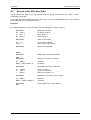
Slots Permitted for the CP 242-2 in the SIMATIC S7-200 System .................................... 2-8
Types of Operation With the CP 242-2............................................................................. 2-8
Addressing the CP 242-2 in the PLC ................................................................................ 2-9
Configuring the CP 242-2 ................................................................................................2-11
3
Interface to the User Program .................................................................. 3-1
3.1
Overview......................................................................................................................... 3-1
3.2
3.2.1
3.2.2
3.2.3
3.2.4
Meaning of the Data in the Digital Module.................................................................... 3-2
Identification Register....................................................................................................... 3-2
Error Register................................................................................................................... 3-2
Status Byte....................................................................................................................... 3-3
Control Byte ..................................................................................................................... 3-3
3.3
3.3.1
3.3.2
3.3.3
3.3.4
3.3.5
Meaning of the Data in the Analog Module .................................................................. 3-5
Identification Register....................................................................................................... 3-5
Error Register................................................................................................................... 3-5
Access to the Analog Input and Output Words.................................................................. 3-5
Analog Input Area ............................................................................................................ 3-6
Analog Output Area.......................................................................................................... 3-8
4
Standard Operation................................................................................... 4-1
4.1
How the PLC Addresses the Slaves on the AS-i Cable................................................ 4-1
4.2
Access to the AS-i User Data......................................................................................... 4-3
4.3
Signaling Errors and Diagnostics ................................................................................. 4-4
5
Extended Operation .................................................................................. 5-1
5.1
How the Command Interface Functions ....................................................................... 5-1
I-1
Contents
B8976105/01
5.2
5.2.1
5.2.1.1
5.2.1.2
5.2.1.3
5.2.1.4
5.2.1.5
5.2.1.6
5.2.1.7
5.2.1.8
5.2.1.9
5.2.1.10
5.2.1.11
5.2.1.12
5.2.1.13
5.2.1.14
5.2.1.15
5.2.1.16
5.2.1.17
5.2.1.18
5.2.1.19
5.2.1.20
5.2.1.21
5.2.1.22
5.2.1.23
5.2.1.24
5.2.1.25
Description of the AS-i Commands............................................................................... 5-4
Commands Supported by the CP 242-2 ........................................................................... 5-4
Set_Permanent_Parameter.............................................................................................. 5-9
Get_Permanent_Parameter ............................................................................................. 5-9
Write_Parameter.............................................................................................................5-10
Read_Parameter.............................................................................................................5-10
Store_Actual_Parameters ...............................................................................................5-11
Set_Permanent_Configuration ........................................................................................5-11
Get_Permanent_Configuration ........................................................................................5-12
Store_Actual_Configuration.............................................................................................5-13
Read Actual Configuration Data ......................................................................................5-13
Set_LPS..........................................................................................................................5-14
Set_Offline_Mode ...........................................................................................................5-15
Select Autoprogramming.................................................................................................5-16
Set_Operation_Mode ......................................................................................................5-17
Change_Slave_Address ..................................................................................................5-18
Read Slave Status ..........................................................................................................5-19
Read Lists and Flags (Get_LPS, Get_LAS, Get_LDS, Get_Flags)...................................5-20
Read Total Configuration ................................................................................................5-22
Configure Total System...................................................................................................5-24
Write Parameter List .......................................................................................................5-27
Read Parameter Echo List ..............................................................................................5-28
Read Version ID..............................................................................................................5-29
Read and Delete Slave Status.........................................................................................5-30
Read Slave ID.................................................................................................................5-31
Read Slave I/O ...............................................................................................................5-32
Read Data and Delta List ................................................................................................5-33
6
Replacing a Defective Slave / Automatic Address Programming ......... 6-1
7
Error Indicators of the CP 242-2 / Dealing with Errors........................... 7-1
A
AS-Interface Protocol Implementation
Conformance Statement (PICS) ............................................................ A-1
A.1
PICS for CP 242-2 .......................................................................................................
B
References .............................................................................................. B-1
C
Abbreviations and Glossary.................................................................. C-1
D
Notes on the CE Label ........................................................................... D-1
I-2
A-1
B8976105/01
1
AS-i Master Module CP 242-2
Introduction
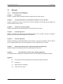
This manual describes the functions and programming of the CP 242-2. Before you read this manual,
it is assumed that you know the contents of the manual 'AS-Interface Introduction and Basic
Information’.
We recommend the following procedure when...
...you want an overall picture of the ASInterface.
´
Read
the
manual
‘AS-Interface
Introduction and Basic Information'. This
manual contains general information
about the AS-Interface, generally referred
to as AS-i in this manual.
...you want to know how to program the
CP 242-2.
´
Read
the
manual
'AS-Interface
Introduction and Basic
Infomation'
Chapter 1. You should also read Chapters
4 and 5 in this manual.
...you want to start up the PLC master
module CP 242-2.
´
You will find the information you require in
Chapter 2 “Technical Description and
Installation Guidelines for the CP 242-2”
and in Chapter 3 “Interface to the User
Program”.
...you want to create a PLC program for
standard applications.
´
Chapter 4 contains all the information you
require about “Standard Operation”.
...you require additional information about
the extended mode.
´
You will find the required information in
Chapter 5.
1-1
AS-i Master Module CP 242-2
1.1
B8976105/01
General
1.1.1
Overview of the Chapters
Chapter 1
Introduction
Chapter 1 contains general information about the layout and use of the manual.
Chapter 2
Technical Description and Installation Guidelines for the CP 242-2
Chapter 2 provides you with an overview of the modes, installation and startup and the display and
control elements of the CP 242-2.
Chapter 3
Interface to the User Program
Chapter 3 describes the interface between an S7-200 CPU and a CP 242-2.
Chapter 4
Standard Operation
Chapter 4 describes the extremely simple standard operation of the module. This type of operation
allows access to the inputs and outputs of the AS-i slaves.
Chapter 5
Extended Operation
Chapter 5 describes the extended operation of the CP 242-2. In this type of operation, the AS-i slaves
can be assigned parameters or the slave addresses can be modified by the S7 program.
Chapter 6
Replacing a Defective Slave / Automatic Address Programming
Chapter 6 explains the simple procedure for replacing a failed AS-i slave.
Chapter 7
Error Indicators of the CP 242-2 / Dealing with Errors
This chapter lists the possible error indications of the CP 242-2 and describes possible remedies.
Appendix
A
AS-Interface Protocol Implementation Conformance Statement (PICS)
B
References
C
Abbreviations and Glossary
D
Notes on the CE Label
1-2
B8976105/01
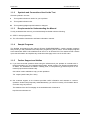
1.1.2
AS-i Master Module CP 242-2
Symbols and Conventions Used in the Text
General symbols in the text:
This symbol indicates an action for you to perform.
±
This symbol indicates a list.
This symbol highlights special features or dangers.
1.1.3
Requirements for Understanding the Manual
To fully understand the manual, you should already be familiar with the following:
±
STEP 7 microprogramming
±
The ‘AS-Interface Introduction and Basic Information' manual.
1.1.4
Sample Programs
The diskette accompanying this manual (S7-200 'SAMPLE/BEISPIEL') contains sample programs
that provide you with instructions and help when programming the CP 242-2. These sample programs
were created with STEP 7 Micro/WIN and can be run on an S7-200 CPU. The readme.txt file contains
up-to-date information and explains any restrictions that apply to the use of the CP 242-2.
1.1.5
±
Further Support and Hotline
If you have technical questions about using the software and your problem is not dealt with in
the documentation or in the integrated help system, please contact your Siemens representative
or dealer. The addresses are listed in Catalog IK10, in CompuServe (go autforum) and on the
Internet (http://www.aut.siemens.de).
Our hotline is also available to help you with problems:
Tel. +49(911) 895–7000 (Fax -7001)
±
Our customer support on the Internet provides useful information and answers to common
questions. Under FAQ (Frequently Asked Questions), you will find a variety of information about
our entire range of products.
The address of the AUT homepage in the worldwide web of Internet is:
http://www.aut.siemens.de.
1-3
AS-i Master Module CP 242-2
B8976105/01
1-4
B8976105/01
2
AS-i Master Module CP 242-2
Technical Description and Installation Guidelines for
the CP 242-2
This chapter outlines the basic functions of the CP 242-2 and explains how the module is installed
and started up.
You will learn the following:
±
Which PLC systems can be operated using the CP 242-2 on the AS-Interface.
±
How to install the CP 242-2.
±
Which modes are supported by the CP 242-2.
When handling and installing modules, please keep to the guidelines for
electrostatically sensitive devices (ESD guidelines) and follow the instructions in
the manual of the S7-200 'S7-200 Programmable Controller, Hardware and Installation'
/4/.
Insert and remove components and modules only when the power is
turned off.
Immunity to interference / grounding
To ensure that the CP 242-2 is immune to interference, the CP 242-2, the
S7-200 programmable controller and the AS-i power supply unit must be correctly
grounded.
The AS-i power supply unit used must provide a low voltage safely isolated
from the network. Safe isolation can be implemented according
following requirements:
±
VDE 0100 Part 410 = HD 384-4-4 = IEC 364-4-41
(as functional extra-low voltage with safe isolation) or
±
VDE 0805 = EN60950 = IEC 950
(as safety extra-low voltage SELV) or
±
VDE 0106 Part 101
2-1
to
the
AS-i Master Module CP 242-2
2.1
2.1.1
B8976105/01
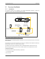
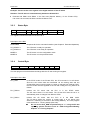
Overview of the Module
Introduction
The CP 242-2 module can be operated in the S7-200 programmable controller. It allows the
connection of an AS-i chain to this programmable controller.
S7-200 CPU
SIEMENS
CPU 212
CP 242-2
AS-Interface
Master
29 24 19 14
28 23 18 13
27 22 17 12
31 26 21 16 11
30 25 20 15 10
SIMATIC
S7-200
9
8
7
6
5
4
3
2
1
0
SF
APF
CER
AUP
CM
X2
34
6GK7 242-2AX00-0XA0
AS-i Master
CP 242-2
Passive modules
(without slave ASIC)
Active modules
(with slave ASIC)
AS-i power supply unit
Actuator/sensor
with AS-i ASIC
AS-i
cable
Active or passive
AS-i module
Figure 1: Example of a System Configuration; S7-200 with CP 242-2
Please refer to the accompanying product information to find out the CPUs with which the CP 242-2
can be operated.
From the point of view of the S7-200 CPU, the CP 242-2 is considered as two expansion modules (an
8DI/8DO digital module and an 8AI/8AO analog module).
The design of the CP 242-2 corresponds to that of a standard expansion module for an S7-200.
With some types of S7-200 CPU, two CP 242-2 master modules can be operated with one CPU.
Components Supplied
The CP 242-2 product includes the following components:
1. The CP 242-2 module
2. Bus connector
2-2
B8976105/01
2.1.2
AS-i Master Module CP 242-2
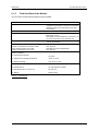
Technical Data of the Module
The CP 242-2 module has the following technical data:
Bus cycle time
Configuration
AS-i master profiles supported
Attachment to the AS-i cable
Address range
Power supply SIMATIC backplane bus
Current consumption from the AS-i cable
Power supply from the AS-i cable
Current consumption from 5 V DC
5 ms with 31 slaves
Using button on the front panel or with the
“Configure Total System” command in extended
operation (Section 5.2 “Description of the AS-i
Commands”)
M1
Via an S7-200 terminal strip for connection of
field wiring (14 pin)
Permissible current loading from connection 1 to
3 or from connection 2 to 4 maximum 3 A
One digital module with 8DI/8DO and one analog
module with 8AI/8AO
5 V DC
max. 100 mA
According to the AS-i specification
max. 200 mA
Ambient conditions
•
•
•
Operating temperature
0 to 60°C
Transport and storage temperature
-40°C to +70°C
Relative humidity
max. 95% at +25°C
Construction
•
•
•
Module format
S7-200 expansion module
Dimensions (W x H x D) in mm
90 x 80 x 62
Weight
approx. 200 g
Table 2-1
Technical Data
2-3
AS-i Master Module CP 242-2
2.1.3
B8976105/01
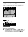
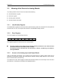
Display and Control Elements of the CP 242-2
The following diagram shows the front panel of the CP 242-2 with its displays and control elements.
The AS-i cable is connected below the front panel at the front of the CP 242-2. The SET and
DISPLAY buttons are below the front cover on the front of the CP 242-2.
1
-
+
+
-
6
10
14
CP 242-2
AS-Interface
Master
29
24
19
14
9
4
SF
28
23
18
13
8
3
APF
27
22
17
12
7
2
CER
31 26
21
16
11
6
1
AUP
30 25
20
15
10
5
0
CM
SET
X 2
3 4
6GK7 242-2AX00-0XA0
DISPLAY
Figure 2-3 Front View of the CP 242-2 With Cover Removed
AS-i + (brown)
AS-i - (blue)
1
+
-
+
-
6
10
14
Figure 2-4 Connection of the AS-i Cable
The CP 242-2 has connections for two AS-i cables that are jumpered internally in the CP 242-2. This
allows the CP 242-2 to be “looped into” the AS-i cable.
The load capacity of the contacts is a maximum of 3 A. If this value is exceed on the
AS-i cable, the CP 242-2 must not be “looped into” the AS-i cable but must be
connected by a separate cable (in this case only one terminal pair of the CP 242-2 is
used).
The CP 242-2 must be connected to the grounding conductor via the
2-4
terminal.
B8976105/01
AS-i Master Module CP 242-2
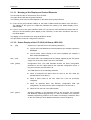
2.1.3.1 Meaning of the Display and Control Elements
The front panel of the CP 242-2 has a row of 8 LEDs.
The upper three LEDs are the group indicators.
The meaning of the lower 5 LEDs depends on the status of the group indicators.
±
If none of the group indicator LEDs is lit, the lower 5 LEDs indicate the status of the CP 242-2.
The labeling to the right of the LEDs then indicates the meaning. The default display is this
status display.
±
If one or more of the group indicator LEDs is lit, the lower 5 LEDs indicate the slaves that are
active on the AS-Interface (slave display of the CP 242-2). In this case, the label to the left of
the LEDs applies.
The display can be switched over using the DISPLAY button.
The SET button is used to configure the CP 242-2.
2.1.3.2 Status Display of the CP 242-2 (All Group LEDs Off)
SF
(red)
System error. This LED is lit in the following situations:
±
The CP 242-2 has detected an internal problem (for example a defective
EEPROM).
±
The CP 242-2 cannot change to the mode requested (for example a
slave exists with address 0).
APF (red)
AS-i Power Fail. This indicates that the voltage supplied by the AS-i power
supply unit on the AS-i cable is too low or has failed.
CER (yellow)
Configuration Error. This LED indicates whether the slave configuration
detected on the AS-i cable matches the expected configuration (LPS). If
they do not match, the CER LED is lit.
The CER LED is lit in the following situations:
±
When a configured AS-i slave does not exist on the AS-i cable (for
example failure of the slave).
±
When a slave exists on the AS-i cable but it was not previously
configured.
±
When an attached slave has different configuration data (I/O
configuration, ID code) from the slave configured on the CP 242-2.
±
AUP (green)
When the CP 242-2 is in the offline phase.
Autoprog available. In the protected mode of the CP 242-2, this indicates
that automatic address programming of a slave is possible. The automatic
address programming makes it much easier to exchange a defective slave
on the AS-i cable (for more detailed information refer to Chapter 6).
2-5
AS-i Master Module CP 242-2
CM
(yellow)
B8976105/01
Configuration Mode. This displays the operating mode of the CP 242-2.
LED lit:
LED unlit:
Configuration mode
Protected mode
The configuration mode is only required when installing the CP 242-2. In the
configuration mode, the CP 242-2 activates all connected slaves and exchanges
data with them. For more information about the configuration mode, refer to
Section. 2.1.7 .
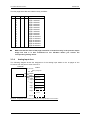
2.1.3.3 Slave Indicators of the CP 242-2 (At Least One Group LED is Lit)
The activated slaves are displayed in groups of five. The upper three group LEDs indicate which
group of five is being displayed. The lower five LEDs indicate the active slaves within this group. You
can switch over to the slave display mode used by pressing the DISPLAY button. You switch from
group to group by pressing the DISPLAY button again:
You can return to the status display as follows:
±
After displaying the last group (slaves 30, 31) and pressing the DISPLAY button.
±
If you do not press the DISPLAY button for a longer period of time (approximately 8 minutes).
In the protected mode, failed or existing but unconfigured slaves are indicated by the corresponding
LED flashing.
Example:
The group LEDs indicate the second group of five.
Within this group, the active slaves 6 and 8 are displayed by the lower five LEDs.
29
24
28
23
27
22
31
26
21
30
25
20
SF
14
9
4
18
13
8
3
APF
17
12
7
2
CER
16
11
6
1
AUP
15
10
5
0
CM
19
Figure 2-5 Example of a Status Display
2-6
B8976105/01
AS-i Master Module CP 242-2
2.1.3.4 Meaning of the Buttons
SET button
The SET button is required for configuring the CP 242-2 in standard
operation.
±
This button is only effective when the PLC_RUN bit is set to ‘0’
in the control byte of the CP 242-2. This is always the case when
the S7-200 CPU is in the STOP mode.
If the CP 242-2 is in the configuration mode (the “CM” LED is lit), you
can configure automatically by pressing the button the CP 242-2.
Configuration involves the following steps:
1. The CP 242-2 saves the existing slave configuration as indicated by
the LEDs of the active slaves as the expected configuration.
2. The CP 242-2 then switches to the protected mode.
If a slave with address '0' exists, the CP 242-2 does not switch from
the configuration mode to the protected mode. The SF LED signals
an error while the SET button is pressed.
±
If the CP 242-2 is in the protected mode (“CM” LED is not lit), pressing
the button on the CP 242-2 switches to the configuration mode.
Pressing the button while the AS-i Power Fail LED is lit resets
the CP 242-2 to its default status, as follows:
±
No slaves are configured
±
All slave parameters are set
±
Automatic
address
programming
(AUTO_ADDRESS_ENABLE = ‘1’)
is
activated
For more detailed information about configuring the CP 242-2, refer to Section 2.1.7.
DISPLAY button
The DISPLAY button is used to change the LED display of the CP 242-2. If
you press this button, the display changes from the status display to the
slave display. The first group of five slaves is then displayed. To move on to
the next group of five slaves, press the button again.
2-7
AS-i Master Module CP 242-2
2.1.4
B8976105/01
Slots Permitted for the CP 242-2 in the SIMATIC S7-200 System
The CP 242-2 can be inserted in all slots for expansion modules in the S7-200 programmable
controller.
There may, however, be restrictions depending on the CPU or power supply unit being used in terms
of the following:
±
Expandability with several expansion modules,
±
The electrical configuration, in other words the total current consumption from the S7 backplane
bus.
2.1.5
Before starting up, you should calculate the total power requirements of your S7-200
system.
To do this, use the calculation table in the manual
“S7-200 Programmable Controller, Installation and Hardware”
Types of Operation With the CP 242-2
With the CP 242-2 module, two types of operation are possible:
±
Standard operation
±
Extended operation
The difference between the two types of operation is as follows:
Standard Operation
In this type of operation, the user program accesses the user data of the AS-i slaves and the
diagnostic data of the CP 242-2. Programming is simple and this type of operation is adequate for the
majority of automation tasks.
In standard operation, no commands or special parameters can be transferred to the slaves on the
AS-i cable. This type of operation corresponds to the profile M0 of the AS-i master specification.
Extended Operation
In extended operation, the user program uses the command interface of the CP 242-2.
This means that the entire range of functions in the AS-i system are available to the PLC
programmer. In particular, the AS-i master calls (for example to assign parameters to slaves) are
available. This type of operation corresponds to profile M1 of the AS-i master specification.
2-8
B8976105/01
2.1.6
AS-i Master Module CP 242-2
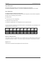
Addressing the CP 242-2 in the PLC
From the point of view of the S7-200 CPU, the CP 242-2 behaves logically as if it were two
consecutive expansion modules:
±
The first module is an 8DI/8D0 digital module. It occupies 8 input and 8 output bits in the
address base of the digital inputs and outputs.
The 8 input bits form the status byte of the CP 242-2. Using this byte, the CP 242-2
transfers status information to the PLC user program.
The 8 output bits form the control byte of the CP 242-2. Using this, the PLC user program
controls the CP 242-2.
±
The second module is an 8AI/8AO analog module. It occupies 16 input and 16 output bytes in
the address area of the analog inputs and outputs.
±
In standard operation, both the user data of the AS-i slaves and the diagnostic information of the
CP 242-2 are transferred via these 16 I/O bytes.
In extended operation, the 16 I/O bytes are also used to transfer commands.
The start addresses of the address area are decided by the S7-200 CPU being used and the slot in
which the CP 242-2 is inserted.
For more detailed information about addressing, refer to the manuals of the S7-200 programmable
controller.
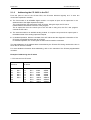
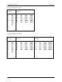
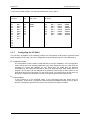
Example of addressing the CP 242-2
1. CPU 212 and one CP 242-2
CPU 212
I0.0
I0.1
I0.2
I0.3
I0.4
I0.5
I0.6
I0.7
CP 242-2
Q0.0
Q0.1
Q0.2
Q0.3
Q0.4
Q0.5
I1.0
I1.1
I1.2
I1.3
I1.4
I1.5
I1.6
I1.7
Q1.0
Q1.1
Q1.2
Q1.3
Q1.4
Q1.5
Q1.6
Q1.7
AIW0
AIW2
AIW4
AIW6
AIW8
AIW10
AIW12
AIW14
AQW0
AQW2
AQW4
AQW6
AQW8
AQW10
AQW12
AQW14
2-9
AS-i Master Module CP 242-2
B8976105/01
2. CPU 214 and one CP 242-2
CPU 214
I0.0
I0.1
I0.2
I0.3
I0.4
I0.5
I0.6
I0.7
I1.0
I1.1
I1.2
I1.3
I1.4
I1.5
CP 242-2
Q0.0
Q0.1
Q0.2
Q0.3
Q0.4
Q0.5
Q0.6
Q0.7
Q1.0
Q1.1
I2.0
I2.1
I2.2
I2.3
I2.4
I2.5
I2.6
I2.7
Q2.0
Q2.1
Q2.2
Q2.3
Q2.4
Q2.5
Q2.6
Q2.7
AIW0
AIW2
AIW4
AIW6
AIW8
AIW10
AIW12
AIW14
AQW0
AQW2
AQW4
AQW6
AQW8
AQW10
AQW12
AQW14
3. CPU 214 and two CP 242-2s
CPU 214
I0.0
I0.1
I0.2
I0.3
I0.4
I0.5
I0.6
I0.7
I1.0
I1.1
I1.2
I1.3
I1.4
I1.5
CP 242-2
Q0.0
Q0.1
Q0.2
Q0.3
Q0.4
Q0.5
Q0.6
Q0.7
Q1.0
Q1.1
I2.0
I2.1
I2.2
I2.3
I2.4
I2.5
I2.6
I2.7
CP 242-2
Q2.0
Q2.1
Q2.2
Q2.3
Q2.4
Q2.5
Q2.6
Q2.7
AIW0
AIW2
AIW4
AIW6
AIW8
AIW10
AIW12
AIW14
AQW0
AQW2
AQW4
AQW6
AQW8
AQW10
AQW12
AQW14
2-10
I3.0
I3.1
I3.2
I3.3
I3.4
I3.5
I3.6
I3.7
Q3.0
Q3.1
Q3.2
Q3.3
Q3.4
Q3.5
Q3.6
Q3.7
AIW16
AIW18
AIW20
AIW22
AIW24
AIW26
AIW28
AIW30
AQW16
AQW18
AQW20
AQW22
AQW24
AQW26
AQW28
AQW30
B8976105/01
AS-i Master Module CP 242-2
4. CPU 214, one 8DI module, one 3AI/1AO module and one CP 242-2
CPU 214
I0.0
I0.1
I0.2
I0.3
I0.4
I0.5
I0.6
I0.7
I1.0
I1.1
I1.2
I1.3
I1.4
I1.5
2.1.7
Q0.0
Q0.1
Q0.2
Q0.3
Q0.4
Q0.5
Q0.6
Q0.7
Q1.0
Q1.1
8DI
3AI / 1AO
I2.0
I2.1
I2.2
I2.3
I2.4
I2.5
I2.6
I2.7
AIW0
AIW2
AIW4
CP 242-2
AQW0
I3.0
I3.1
I3.2
I3.3
I3.4
I3.5
I3.6
I3.7
Q2.0
Q2.1
Q2.2
Q2.3
Q2.4
Q2.5
Q2.6
Q2.7
AIW8
AIW10
AIW12
AIW14
AIW16
AIW18
AIW20
AIW22
AQW4
AQW6
AQW8
AQW10
AQW12
AQW14
AQW16
AQW18
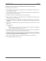
Configuring the CP 242-2
The CP 242-2 is capable of two operating modes, the configuration mode and the protected mode.
When supplied, the CP 242-2 is in the configuration mode as indicated by the “CM” LED being lit.
±
Configuration Mode:
The configuration mode is used to install and start up an AS-i installation. In the configuration
mode, the CP 242-2 can exchange data with every slave attached to the AS-i cable (with the
exception of a slave with address “0”). Any slaves that are added later are detected
immediately by the master and included in the cyclic data exchange. After testing the PLC
program, the CP 242-2 can be changed to the protected mode using the SET button on the
front panel while the S7-200 CPU is in the STOP mode. Any slaves active at this point are
therefore configured and included in the list of configured (permanent) slaves (LPS).
±
Protected Mode:
If the CP 242-2 is in the protected mode, it only exchanges data with slaves that are
“configured”. In this sense, “configured” means that the slave address saved on the CP 242-2
and the configuration data stored on the CP 242-2 match the values of a slave.
2-11
AS-i Master Module CP 242-2
B8976105/01
Configuration of the CP 242-2 during installation and startup of the AS-i network
The following situation is assumed:
The connected AS-i slaves have been supplied with unique addresses (for example using an
address programming device).
The AS-Interface is complete, in other words the AS-i power supply unit is in operation and the
slaves are connected to the AS-i cable.
To configure the CP 242-2 in standard operation, follow the steps below:
Switch the PLC to the STOP mode. This ensures that bit 7 (PLC_RUN) in the control byte of the
CP 242-2 is set to ‘0’ (see Section 3.2).
Change the CP 242-2 to the configuration mode (press the SET button of the CP 242-2; the
“CM” LED is lit). If the CP 242-2 is already in the configuration mode (as supplied), this step can
be omitted.
Switch the PLC to RUN and set bit 7 (PLC_RUN) in the control byte of the CP 242-2 to ‘1’ (see
Section 3.2).
Test your program.
Note:
In the configuration mode, you can add or remove slaves on the AS-i cable. Newly added
slaves are activated immediately by the CP 242-2.
On completion of the installation of the AS-Interface, switch the PLC to STOP. This makes sure
that bit 7 (PLC_RUN) in the control byte of the CP 242-2 is set to ‘0’.
Now press the SET button of the CP 242-2 again. The CP 242-2 saves the actual configuration
indicated by the active slaves display as the desired configuration and switches to the protected
mode. In the protected mode, the “CM” LED is switched off.
Switch the PLC to RUN and set bit 7 (PLC_RUN) in the control byte of the CP 242-2 to ‘1’.
This completes installation of the CP 242-2.
2-12
B8976105/01
3
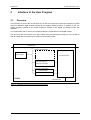
3.1
AS-i Master Module CP 242-2
Interface to the User Program
Overview
From the point of view of the S7-200 CPU, the CP 242-2 occupies two consecutive expansion module
slots (one 8DI/8DO digital module followed by an 8AI/8AO analog module). In addition to this, the
system registers required for an S7-200 expansion module for the digital and analog module are
available.
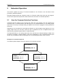
The S7-200 CPU and CP 242-2 AS-i master module are coordinated via the digital module.
The slave I/O data, the transfer of the AS-i master calls (commands) and reading in of the response
data and diagnostic information are handled on the analog module.
S7-200 I/O bus
DPRAM (= analog module)
System register
AS-Interface master
8 data input words (8AI)
8 data output words (8AO)
I/O register (= digital module)
8 status bits (8DI)
8 control bits (8DO)
CP 242-2
AS-Interface cable
Figure 3-5 Data Model of the CP 242-2 in Terms of the CPU Interface
3-1
AS-i Master Module CP 242-2
3.2
B8976105/01
Meaning of the Data in the Digital Module
The digital module of the CP 242-2 consists of four registers:
±
8-bit identification register
±
8-bit error register
±
8-bit input register 8DI (status byte of the CP 242-2)
±
8-bit output register 8DO (control byte of the CP 242-2)
3.2.1
Identification Register
The identification register can be read via the special memory area of the S7-200 CPU and produces
the fixed value 05 hex. This signals the existence of an 8DI/8DO digital module.
The address at which the program can access the identification register depends on the slot in which
the CP 242-2 is inserted.
Example
Situation: The CP 242-2 is inserted directly beside the S7-200 CPU.
The content of the identification register can be read from SMB8.
3.2.2
Error Register
The error register has the following structure:
Bit 7
0
Bit 6
0
Bit 5
0
Bit 4
0
Bit 3
0
Bit 2
APF
Bit 1
0
Bit 0
CER
The CP 242-2 signals PLC interface errors to the user program using this register.
Description of the Bits:
APF= 1
AS-i Power Fail
Indicates that the voltage supplied by the AS-i power supply unit on the AS-i cable is
too low or has failed.
The APF LED is lit
(see Section 2.1.3.2 Status Display of the CP 242-2 (All Group LEDs Off))
APF=0
AS-i voltage correct
The APF LED is off.
CER=1
Configuration error (only in the protected mode)
This indicates a difference between the slave configuration detected on the
AS-i cable and the desired configuration configured on the CP 242-2.
The CER LED is lit (see Section 2.1.3.2 status display of the CP 242-2)
CER=0
Configuration correct (only in the protected mode)
The CER LED is off
3-2
B8976105/01
AS-i Master Module CP 242-2
Example : Access to the error register in the digital module of the CP 242-2
Situation: The CP 242-2 is inserted directly beside the S7-200 CPU
Evaluate bits SM9.0 and SM9.2 in the SM area (Special Memory of the S7-200 CPU).
If an error has occurred, bit SM 9.0 and/or bit SM9.2 is set.
3.2.3
Bit 7
0
Status Byte
Bit 6
RESPONSE
Bit 5
0
Bit 4
0
Bit 3
0
Bit 2
0
Bit 1
CP_READY
Bit 0
MODE
This register indicates the status of the CP 242-2.
Description of the Bits:
RESPONSE
Response bit for the command interface (see Chapter 5. Extended Operation)
CP_READY=1
CP_READY=0
The CP 242-2 is ready for operation
The CP 242-2 is not ready for operation
MODE=1
MODE=0
The CP 242-2 is in the configuration mode
The CP 242-2 is in the protected mode
3.2.4
Control Byte
Bit 7
Bit 6
Bit 5
PLC_RUN COMMAND 0
Bit 4
0
Bit 3
BS3
Bit 2
BS2
Bit 1
BS1
Bit 0
BS0
The user program controls the data exchange with the CP 242-2 using this register.
Description of the Bits:
PLC_RUN
In the STOP mode of the S7-200 CPU, the CP must send ‘0’ to all slaves.
Since the AS-i slave data are transferred via the analog area and the
S7-200 CPU does not set this area to '0' when it changes from RUN to STOP,
the CPU mode must be signaled to the CP 242-2 using the PLC_RUN bit as
follows:
PLC_RUN=0
Informs the CP 242-2 that the PLC is in the STOP mode.
The CP 242-2 sends '0' to all slaves. The S7-200 CPU sets the bit to '0'
automatically when it changes from RUN to STOP.
PLC_RUN=1
Informs the CP 242-2 that the PLC is in the RUN mode.
The CP 242-2 sends the content of output page 0 to all slaves (see
Section 3.3 “Meaning of the Data in the Analog Module”). The user program
must set this bit to '1' during startup (first scan).
Do not set the PLC_RUN bit permanently to “1” using the S7-200
operating system functions such as “CPU Configuration/Setting
Outputs” or “Forcing Outputs”.
3-3
AS-i Master Module CP 242-2
B8976105/01
COMMAND
Job bit for the command interface (see Chapter 5. Extended Operation)
BS3_BS0
Page select bits for page changeover in the analog module (see Section 3.3
Meaning of the Data in the Analog Module)
3-4
B8976105/01
3.3
AS-i Master Module CP 242-2
Meaning of the Data in the Analog Module
The analog module of the CP 242-2 consists of the following:
±
8-bit identification register
±
8-bit error register
±
8 analog input words 8AI
±
8 analog output words 8AO
3.3.1
Identification Register
The identification register can be read via the special memory area of the S7-200 CPU and produces
the fixed value 1F hex. This signals the existence of an 8AI/8AO analog module.
3.3.2
Error Register
The error register has the following structure:
Bit 7
0
Bit 6
0
Bit 5
0
Bit 4
0
Bit 3
0
Bit 2
APF
Bit 1
0
Bit 0
CER
This register signals CP 242-2 errors to the user program.
3.3.3
The error register of the digital and the analog module provides the user with the same
information about the error state of the CP 242-2.
The meaning of the individual bits was described in Section 3.2 Meaning of the Data in
the Digital Module.
Access to the Analog Input and Output Words
Using a page-select mechanism, the 8 analog input words and the 8 analog output words can be
switched to 16 different analog input areas and 16 different analog output areas on the CP 242-2.
Each of these areas is 8 words long.
The switchover to the various pages is made with bits BS3 to BS0 in the control byte of the CP 242-2
(see Section 3.2 “Meaning of the Data in the Digital Module”).
3-5
AS-i Master Module CP 242-2
B8976105/01
The four page select bits are coded in binary as follow:
BS3
0
0
0
0
0
0
0
0
1
1
1
1
1
1
1
1
BS2
0
0
0
0
1
1
1
1
0
0
0
0
1
1
1
1
BS1
0
0
1
1
0
0
1
1
0
0
1
1
0
0
1
1
BS0
0
1
0
1
0
1
0
1
0
1
0
1
0
1
0
1
Page No.
Page 0 selected
Page 1 selected
Page 2 selected
Page 3 selected
Page 4 selected
Page 5 selected
Page 6 selected
Page 7 selected
Page 8 selected
Page 9 selected
Page 10 selected
Page 11 selected
Page 12 selected
Page 13 selected
Page 14 selected
Page 15 selected
Make sure that the value of the page select bits is located not only in the process output
image but that it is also transferred to the CP 242-2 before you access the
corresponding analog values.
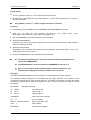
3.3.4
Analog Input Area
The following diagram shows the assignment of the analog input words to the 16 pages of the
CP 242-2 from the point of view of the PLC.
S7-200 CPU
CP 242-2
Page-select bits
SPS view
Memory assignment
BS3...BS0
Page 0
8 AIW
··
·
Page 1
Slave inputs
Diagnostics
Page 2
Response data
Page 3
Response data
Page 4
Response data
Page 5
Response data
Page 6
reserved
Page 15
Figure 3-6 Assignment of the 8 Analog Input Words to the Page Structure of the CP 242-2
3-6
B8976105/01
AS-i Master Module CP 242-2
Page 0 Slave Inputs
Using these analog input words, you can access the input bits of the AS-i slaves.
The structure is described in Section 4.1 “How the PLC Addresses the Slaves on the AS-i Cable”.
Page 1 Diagnostics
This page indicates the delta list of the AS-i slaves.
The delta list contains any differences between the actual configuration and the desired configuration.
By setting a bit, the following can be indicated:
±
Missing slaves
±
Extra slaves (not in the configuration)
±
Slaves with incorrect I0/ID coding
The delta list is updated both in the configuration and in the protected mode.
The bytes and bits of the delta list are ordered as shown in the table below. (M: start address of the
analog input area of the CP 242-2)
Byte \ Bit Bit 7
Bit 6
Bit 5
Bit 4
Bit 3
Bit 2
Bit 1
Bit 0
Byte m+0
Byte m+1
Byte m+2
Byte m+3
slave 6
slave 14
slave 22
slave 30
slave 5
slave 13
slave 21
slave 29
slave 4
slave 12
slave 20
slave 28
slave 3
slave 11
slave 19
slave 27
slave 2
slave 10
slave 18
slave 26
slave 1
slave 9
slave 17
slave 25
slave 0
slave 8
slave 16
slave 24
slave 7
slave 15
slave 23
slave 31
Pages 2 to 5 Response Data
These pages contain the response data of the command calls. The data structures used and the
codings are described in Chapter 5. The number of pages used depends on the particular command.
Pages 6 to 15
These areas are reserved for later expansions and cannot be used.
3-7
AS-i Master Module CP 242-2
3.3.5
B8976105/01
Analog Output Area
The following diagram shows the assignment of the analog output words to the 16 pages of the
CP 242-2 from the point of view of the PLC.
S7-200 CPU
CP 242-2
Page-select bits
PLC view
Memory assignment
BS3...BS0
Page 0
8 AQW
··
·
Page 1
Slave outputs
reserved
Page 2
Command data
Page 3
Command data
Page 4
Command data
Page 5
Command data
Page 6
reserved
Page 15
Figure 3-7 Assignment of the 8 Analog Output Words to the Page Structure of the CP 242-2
Page 0 Slave Outputs
Using this analog output area, you can access the output bits of the AS-i slaves.
The structure is described in Section 4.1.
Page 1 Reserved
This area is reserved for later expansions and cannot be used.
Pages 2 to 5 Command Data
Using this area, you store command calls on the CP 242-2. The data structures and codings used are
described in Chapter 5. The number of pages used depends on the particular command.
Pages 5 to 15
These areas are reserved for later expansions and cannot be used.
3-8
B8976105/01
4
AS-i Master Module CP 242-2
Standard Operation
Standard operation represents the most common and at the same time simplest use of the CP 242-2.
It allows access to the inputs and outputs of the slaves.
4.1
How the PLC Addresses the Slaves on the AS-i Cable
Before you can access the I/O data of the AS-i slaves, the following requirements must be met:
±
Set the “PLC_RUN” bit (bit 7) in the digital control byte to ‘1’ at the beginning of the cyclic
program.
±
Leave the page selection bits (bits 0 to 3) in the digital control byte at ‘0’.
±
Access to the I/O data of the slaves is then only allowed when the “CP_Ready” bit (bit 1) in the
digital status byte is set to ‘1’.
The CP 242-2 assigns four bits (a nibble) to every slave on the AS-i cable. The PLC can write (slave
output data) and read (slave input data) this nibble. This allows bi-directional slaves to be addressed.
Assignment of the input data of the slaves
Byte Number
Bit 7-4
Bit 3-0
m+0
reserved
slave 1
m+1
m+2
m+3
m+4
m+5
m+6
m+7
m+8
m+9
m+10
m+11
m+12
m+13
m+14
m+15
slave 2
slave 4
slave 6
slave 8
slave 10
slave 12
slave 14
slave 16
slave 18
slave 20
slave 22
slave 24
slave 26
slave 28
slave 30
slave 3
slave 5
slave 7
slave 9
slave 11
slave 13
slave 15
slave 17
slave 19
slave 21
slave 23
slave 25
slave 27
slave 29
slave 31
bit 4
bit 4
| bit 3
| bit 2
| bit 1
bit 4
| bit 3
| bit 3
| bit 2
| bit 2
| bit 1
| bit 1
m = start address of the analog input area of the CP 242-2
The table shows the assignment of the slave input bits to the analog input bytes of the PLC.
4-1
AS-i Master Module CP 242-2
B8976105/01
Assignment of the output data of the slaves
Byte Number
Bit 7-4
Bit 3-0
n+0
reserved
slave 1
bit 4
n+1
n+2
n+3
n+4
n+5
n+6
n+7
n+8
n+9
n+10
n+11
n+12
n+13
n+14
n+15
slave 2
slave 4
slave 6
slave 8
slave 10
slave 12
slave 14
slave 16
slave 18
slave 20
slave 22
slave 24
slave 26
slave 28
slave 30
bit 4
| bit 3
| bit 2
| bit 1
slave 3
slave 5
slave 7
slave 9
slave 11
slave 13
slave 15
slave 17
slave 19
slave 21
slave 23
slave 25
slave 27
slave 29
slave 31
| bit 3
| bit 2
| bit 1
bit 4
| bit 3
| bit 2
| bit 1
n = start address of the analog output area of the CP 242-2
The table shows the assignment of the slave output bits to the analog output bytes of the PLC.
Example of the PLC addressing a number of slaves
The CP 242-2 with start addresses m = 0 for analog input area and n = 0 for analog
output area.
S7 - 200
Input byte
0
1
2
.
.
.
Slave 1
reserved
Bit 4
Slave 2
Bit 4
Bit 3
Bit 4
Bit 3
Bit 1
Bit 4
Bit 2
Bit 1
Bit 4
Bit 2
Bit 1
Slave 4
Bit 4
7
Bit 3
6
Bit 2
Bit 1
0
Bit 3
Bit 2
Bit 1
1
Bit 2
Bit 1
Slave 5
Slave 30
15
Bit 3
Slave 3
Bit 2
S7 - 200
Output byte
Bit 3
2
.
.
.
5
4
3
2
Bit 4
Bit 3
Bit 1
Bit 4
Bit 3
Bit 2
Bit 1
Bit 4
Bit 2
Bit 1
Bit
Bit43
Slave 2
Bit 4
Bit 3
Bit 4
Bit 3
Bit
Bit10
1
0
15
Bit 4
7
Bit 3
6
Bit 1
Bit 2
Bit 1
Bit 2
Bit 1
Slave
Slave 31
31BitBit32 BitBit21
Bit
Bit10
Slave 5
Slave 30
BitBit21
Bit 2
Slave 3
Bit 2
Slave 4
Slave
Slave 31
Bit
Bit43 31Bit
Bit32
Slave 1
reserved
5
4
3
Bit 3
2
1
0
AS-i slaves
Slave no. 2
Slave no. 3
4I module
2I/2O module
Slave no. 4
Slave no. 31
4O module
4I/4O module
The bits relevant to the user program are shown on a gray background.
The bits on a white background have no significance for the user program.
4-2
B8976105/01
4.2
AS-i Master Module CP 242-2
Access to the AS-i User Data
You access the I/O data of the AS-i slaves using the analog commands of the “STEP 7 Micro”
programming language.
If you want to access individual bits of the slave data, you can use the method shown in the following
sample program (CPU 212 and CP 242-2).
Example 1
The example applies to a CPU 212 with a CP 242-2 plugged in directly beside it:
NETWORK
//Startup processing
LD
SI
RI
//if: bit first scan bit:
//PLC_RUN = 1
//Select page 0
SM0.1
Q1.7, 1
Q1.0, 4
NETWORK
//AS-i I/O processing
LD I1.1
CALL 1
//if: CP 242-2_READY
//then: AS-i I/O processing
NETWORK
//End of main program
MEND
NETWORK
//Begin SBR “AS-i I/O processing”
SBR 1
NETWORK
//Fetch AS-i inputs to V memory
LD SM0.0
BMW AIW0, VW800, 8
//Always 1
//Transfer
NETWORK
//Examples of access to AS-i bits
LD V800.0
A
V815.1
=
V903.2
//If bit 1 of slave 1
//and bit 2 of slave 31
//then bit 3 of slave 7 = 1
NETWORK
//Write from V memory to AS-i outputs
LD SM0.0
BMW VW900, AQW0, 8
//Always 1
//Transfer
NETWORK
RET
//End of SBR “AS-i I/O processing”
4-3
AS-i Master Module CP 242-2
4.3
B8976105/01
Signaling Errors and Diagnostics
If the CP 242-2 recognizes errors on the ASi-Interface (AS-i slave failure, AS-i Power Failure) during
operation, it signals these errors by resetting the input data of the affected slave and by setting the
corresponding bit in the error register in the SM area (Special Memory). The SM byte addresses
depend on the slot of the CP 242-2.
Example:
The CP 242-2 is plugged in directly beside the S7-200 CPU. If an AS-i configuration error occurs in
the protected mode, the CP 242-2 sets bits SM 9.0 and SM 11.0 (both bits provide the user with the
same information: AS-i configuration error).
To obtain more detailed information (which slave has failed), you can read in the delta list via page 1
of the analog input area (see Section 3.3).
Note that the operating system of the S7-200 CPU does not always update the error
register in the SM area before a program cycle. For this reason, it is possible that the
input data of a slave are set to '0' although no error is signaled in the error register. If
you require a consistent view of input data, error bits and the delta list, you can achieve
this using the “Read Data and Delta Lists” command! (see Section 5.2.1.25)
Example 2
The example applies to a CPU 212 with a CP 242-2 plugged in directly beside it:
NETWORK
//Startup processing
LD
SI
RI
//if: first scan bit:
//PLC_RUN = 1
//Select page 0
SM0.1
Q1.7, 1
Q1.0, 4
NETWORK
//AS-i diagnostics
LD I1.1
CALL 2
//if: CP_READY
//then: AS-i diagnostics
NETWORK
//End of main program
MEND
NETWORK
//Begin SBR “AS-i diagnostics”
SBR 2
NETWORK
//Read delta list
LD SM0.0
=I Q1.0
BMW AIW0, VW816, 2
//Always 1
//Select page 1
//Read delta list
NOT
=I Q1.0
//Select page 0
NETWORK
//Examples of access to the delta list:
LD V816.1
O
V819.7
=
Q0.0
//If slave 1 failed
//Or if slave 31 failed
//Then CPU output bit = 1
NETWORK
RET
//End of SBR “AS-i diagnostics”
4-4
B8976105/01
5
AS-i Master Module CP 242-2
Extended Operation
This section explains the range of functions available for the CP 242-2 over and above those
provided by standard operation.
Extended operation allows the complete control of a CP 242-2 master from within the user program.
Access to the inputs and outputs is the same as when the CP 242-2 is in standard operation.
5.1
How the Command Interface Functions
Command calls are made to the CP 242-2 from within the user program. The user specifies the
command call in a command buffer and starts the job. The command buffer is in the analog output
area of the CP 242-2 (for example starting at AQW0 if the CP 242-2 is plugged in directly beside the
CPU 212).
Depending on the command to be executed (see Section 5.2), the job data occupy pages 2 to 5 in the
analog output area of the CP 242-2. When the job is completed, the user is supplied with the job
status and any possible response data in a response buffer.
The response buffer is in the analog input area of the CP 242-2 (for example starting at AIW0 if the
CP 242-2 is plugged in directly beside a CPU 212). Depending on the command executed (see
Section 5.2), the response data occupy pages 2 to 5 in the analog input area of the CP 242-2.
Example of a command sequence
The following status diagram shows the sequence of command execution:
Job completed
COMMAND - bit = ‘0’
RESPONSE - bit = ‘0’
Response data read by user
program
COMMAND - bit = ‘0’
RESPONSE - bit = ‘1’
Start command
COMMAND - bit = ‘1’
RESPONSE - bit = ‘0’
Response data valid
COMMAND - bit = ‘1’
RESPONSE - bit = ‘1’
5-1
AS-i Master Module CP 242-2
B8976105/01
Requirements
±
The PLC_RUN bit is set to '1' in the control byte of the CP 242-2.
±
By setting the CP_READY bit in the status byte to '1’, the CP 242-2 signals that it is ready to
execute commands.
If CP_READY is set to ‘0’, no AS-i program execution is possible.
Sequence
A command is only accepted when the COMMAND and RESPONSE bit are reset.
Write the job data for the required command to
Depending on the command, the job data occupy pages 2 to 5.
Set the COMMAND bit and start execution of the command.
Read the RESPONSE bit.
If this bit is set, the CP 242-2 has completely executed the job and has entered valid response
data in the analog input area.
Read the response data.
Depending on the command that was executed, the response data occupy pages 2 to 5 in the
analog input area of the CP 242-2.
Reset the COMMAND bit in the control byte of the CP 242-2.
±
±
±
the
analog
output
area.
Commands started by the CP 242-2 are executed completely regardless of the
state of the COMMAND bit.
The RESPONSE bit is only reset when the COMMAND bit was set to ‘0’
Byte 1 of the response data (command status) indicates whether or not a
command was completed correctly or whether errors occurred.
Example 3
The following example applies to a CPU 212 with a CP 242-2 plugged in directly beside it.
The example shows the sequence of the Read_Lists_and_Flags command. The execution of the
command is triggered by the rising edge at input I0.0. To simplify the program, 64 bytes are always
transferred to the CP 242-2. When the response is read in from the CP 242-2, 64 bytes are also
transferred.
NETWORK
LD
SI
RI
//Startup processing
SM0.1
Q1.7, 1
Q1.0, 4
//if: first scan bit:
//PLC_RUN = 1
//Select page 0
NETWORK
//AS-i command execution
LD I1.1
MOVW 16#1000, VW932
CALL 3
//if: CP_READY
//Enter “read lists” code
//then: SBR 3
NETWORK
//End of main program
5-2
B8976105/01
MEND
NETWORK
SBR
AS-i Master Module CP 242-2
//Begin SBR “AS-i command execution”
3
NETWORK
//Transfer of the command data
LD
EU
UN
UN
SI Q1.1, 1
BMW VW932, AQW0, 8
SI Q1.0, 1
BMW VW948, AQW0, 8
SI Q1.2, 1
RI Q1.0, 2
BMW VW964, AQW0, 8
SI Q1.0, 1
BMW VW980, AQW0, 8
RI Q1.0, 4
SI Q1.6, 1
//If {trigger bit
//pos. edge
//CP command bit
//CP response bit}
//Then{
//Select page 2
//V memory -> page
//Select page 3
//V memory -> page
//Select page 4
//Select page 4
//V memory -> page
//Select page 5
//V memory -> page
//Select page 0
//CP command bit=1}
NETWORK
//Transfer the response data
LD
U
//If {CP command bit
//CP response bit}
//Then{
//Select page 2
//Page -> V memory
//Select page 3
//Page -> V memory
//Select page 4
//Select page 4
//Page -> V memory
//Select page 5
//Page -> V memory
//Select page 0
//CP command bit=0}
I0.0
Q1.6
I1.6
Q1.6
I1.6
SI Q1.1, 1
BMW AIW0, VW832, 8
SI Q1.0, 1
BMW AIW0, VW848, 8
SI Q1.2, 1
RI Q1.0, 2
BMW AIW0, VW864, 8
SI Q1.0, 1
BMW AIW0, VW880, 8
RI Q1.0, 4
RI Q1.6, 1
NETWORK
RET
//End of SBR “AS-i command execution”
5-3
AS-i Master Module CP 242-2
5.2
B8976105/01
Description of the AS-i Commands
The following sections describe the AS-i command calls that can be sent by the S7-200 system to the
CP 242-2. With these command calls, the CP 242-2 provides the complete functionality of the M1
master profile of the AS-i master specification. In addition to this, the CP 242-2 can be configured
completely using command calls by the S7-200 system.
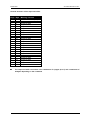
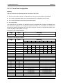
5.2.1
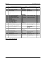
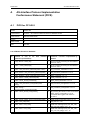
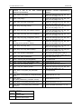
Commands Supported by the CP 242-2
How to use the jobs is explained in the descriptions of the individual jobs, the “AS-Interface
Introduction and Basic Information” manual, the PICS appendix and the detailed explanations in /1/
and /2/.
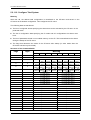
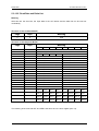
The commands that can be executed are listed in the following table:
5-4
B8976105/01
Section
5.2.1.1
Name
Set_Permanent_Parameter
5.2.1.2
5.2.1.3
Get_Permanent_Parameter
Write_Parameter
5.2.1.4
5.2.1.5
5.2.1.6
Read_Parameter
Store_Actual_Parameters
Set_Permanent_Configuration
5.2.1.7
Get_Permanent_Configuration
5.2.1.8
Store_Actual_Configuration
5.2.1.9
Read Actual Configuration Data
5.2.1.10 Set_LPS
5.2.1.11 Set_Offline_Mode
5.2.1.12 Select Autoprogramming
5.2.1.13 Set_Operation_Mode
5.2.1.14 Change_Slave_Address
5.2.1.15 Read Slave Status
5.2.1.16 Read Lists and Flags (Get_LPS,
Get_LAS, Get_LDS, Get_Flags)
5.2.1.17 Read Total Configuration
5.2.1.18
Configure Total System
5.2.1.19 Write Parameter List
5.2.1.20 Read Parameter Echo List
5.2.1.21 Read Version ID
5.2.1.22 Read and Delete Slave Status
5.2.1.23 Read Slave ID
5.2.1.24 Read Slave I/O
5.2.1.25 Read Data and Delta List
Table 5-2
AS-i Master Module CP 242-2
Parameter
Slave address,
parameter
Slave address
Slave address,
parameter
Slave address
none
Slave address,
configuration
Slave address
none
Slave address
LPS
Mode
Mode
Mode
Address 1, ...2
Slave address
none
Return
Coding:
00H
Parameter
Parameter echo
(optional)
Parameter value
01H
02H
Project. configuration data
Actual configuration data
Error record of the slave
LDS,LAS,LPS,flags
Actual configuration data
actual parameters
LAS, flags
Total
configuration
Parameter list
none
none
Slave address
Slave address
Slave address
none
Overview of the Command Jobs
5-5
03H
04H
05H
06H
07H
08H
09H
0AH
0BH
0CH
0DH
0FH
10H
19H
1AH
Parameter echo list
Version string
Error record of the slave
ID code
I/O configuration
Error bits, input data
delta list
1CH
13H
14H
16H
17H
18H
1DH
AS-i Master Module CP 242-2
B8976105/01
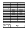
General structure of the command buffer
Page
2
2
2
2
2
2
2
2
2
2
2
2
2
2
2
2
3
3
3
4
4
4
5
5
5
Byte
0
1
2
3
4
5
6
7
8
9
10
11
12
13
14
15
0
:
15
0
:
15
0
:
15
Meaning / Content
Command number
Parameter for job
Parameter for job
Parameter for job
Parameter for job
Parameter for job
Parameter for job
Parameter for job
Parameter for job
Parameter for job
Parameter for job
Parameter for job
Parameter for job
Parameter for job
Parameter for job
Parameter for job
Parameter for job
Parameter for job
Parameter for job
Parameter for job
Parameter for job
Parameter for job
Parameter for job
Parameter for job
Parameter for job
The command buffer can extend over a maximum of 4 pages (2 to 5) with a maximum of
64 bytes depending on the command.
5-6
B8976105/01
AS-i Master Module CP 242-2
General structure of the response buffer:
Page
2
2
2
2
2
2
2
2
2
2
2
2
2
2
2
2
3
3
3
4
4
4
5
5
5
Byte
0
1
2
3
4
5
6
7
8
9
10
11
12
13
14
15
0
:
15
0
:
15
0
:
15
Meaning / Content
Command number (echo)
Command status
Response data
Response data
Response data
Response data
Response data
Response data
Response data
Response data
Response data
Response data
Response data
Response data
Response data
Response data
Response data
Response data
Response data
Response data
Response data
Response data
Response data
Response data
Response data
The response buffer can extend over a maximum of 4 pages (2 to 5) and a maximum of
64 bytes depending on the command.
5-7
AS-i Master Module CP 242-2
B8976105/01
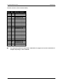
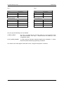
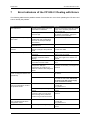
Meaning of the command status in the response buffer:
Value
Meaning
00H
Job completed without error
81H
Slave address incorrect
82H
Slave is not activated (not in LAS )
83H
Error on the AS-Interface
84H
Command not permitted in the current state of the CP 242-2
85H
Slave 0 exists
A1H
Slave with address to be modified not found on AS-Interface
A2H
Slave 0 exists
A3H
Slave with new address already exists on AS-Interface
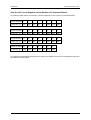
A4H
Slave address cannot be deleted
A5H
Slave address cannot be set
A6H
Slave address cannot be permanently stored
F8H
Job number or job parameter unknown
F9H
EEPROM error
5-8
B8976105/01
AS-i Master Module CP 242-2
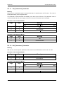
5.2.1.1 Set_Permanent_Parameter
Meaning
With this call, a parameter value for the specified slave is transferred to the CP 242-2. The value is
saved permanently as a configured value.
The parameter is not transferred immediately to the slave by the CP 242-2. The parameter value is
only transferred after the power supply of the PLC is turned on and the slave is activated.
Structure of the Command Buffer
Page
Byte
Meaning
Bit 7
Bit 4 Bit 3
2
0
00H
2
1
Slave address
2
2
irrelevant
Bit 0
Parameter
Structure of the Response Buffer
Page
Byte
Meaning
2
0
00H
2
1
Command status
5.2.1.2 Get_Permanent_Parameter
Meaning
With this call, a slave-specific parameter value stored on the EEPROM of the CP 242-2 is read.
Structure of the Command Buffer
Page
Byte
Meaning
2
0
01H
2
1
Slave address
Structure of the Response Buffer
Page
Byte
Meaning
Bit 7
Bit 4 Bit 3
2
0
01H
2
1
Command status
2
2
irrelevant
5-9
Bit 0
Parameter
AS-i Master Module CP 242-2
B8976105/01
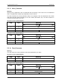
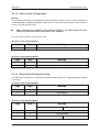
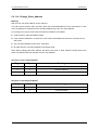
5.2.1.3 Write_Parameter
Meaning
With this call, a parameter value is transferred and sent directly via the AS-i bus to the addressed
slave. The parameter is saved only temporarily on the CP 242-2.
The slave transfers the current parameter value in the response. This can deviate from the values
that have just been written according to the AS-i master specification (/2/). The slave response is
entered in the parameter echo field.
Structure of the Command Buffer
Page
Byte
Meaning
Bit 7
Bit 4 Bit 3
2
0
02H
2
1
Slave address
2
2
irrelevant
Bit 0
Parameter
Structure of the Response Buffer
Page
Byte
Meaning
Bit 7
Bit 4 Bit 3
2
0
02H
2
1
Command status
2
2
irrelevant
Bit 0
Parameter echo
5.2.1.4 Read_Parameter
Meaning
This call returns the current parameter value (actual parameter) of a slave.
Structure of the Command Buffer
Page
Byte
Meaning
2
0
03H
2
1
Slave address
Structure of the Response Buffer
Page
Byte
Meaning
Bit 7
Bit 4 Bit 3
2
0
03H
2
1
Command status
2
2
irrelevant
5-10
Bit 0
Parameter
B8976105/01
AS-i Master Module CP 242-2
5.2.1.5 Store_Actual_Parameters
Meaning
This call overwrites the permanently stored configured parameters with the actual parameters, in
other words the parameters are reconfigured.
Structure of the Command Buffer
Page
Byte
Meaning
2
0
04H
Structure of the Response Buffer
Page
Byte
Meaning
2
0
04H
2
1
Command status
5.2.1.6 Set_Permanent_Configuration
Meaning
This call configures the I/O configuration data and the ID code for the addressed AS-i slave. The data
are stored permanently on the AS-i master CP.
When this command is executed, the CP 242-2 changes to the offline phase and then
returns to normal operation (cold restart on the CP 242-2 and reset on all slaves).
Structure of the Command Buffer
Page
Byte
Meaning
Bit 7
Bit 4 Bit 3
2
0
05H
2
1
Slave address
2
2
ID code
I/O configuration
Structure of the Response Buffer
Page
Byte
Meaning
2
0
05H
2
1
Command status
5-11
Bit 0
AS-i Master Module CP 242-2
B8976105/01
5.2.1.7 Get_Permanent_Configuration
Meaning
This call returns the desired configuration data of an addressed slave stored permanently in the
EEPROM (I/O configuration data and the ID codes).
Structure of the Command Buffer
Page
Byte
Meaning
2
0
06H
2
1
Slave address
Structure of the Response Buffer
Page
Byte
Meaning
Bit 7
Bit 4 Bit 3
2
0
06H
2
1
Command status
2
2
ID code
5-12
Bit 0
I/O configuration
B8976105/01
AS-i Master Module CP 242-2
5.2.1.8 Store_Actual_Configuration
Meaning
This call stores the actual I/O configuration data and actual ID codes of all AS-i slaves permanently
on the EEPROM as desired configuration data. The list of activated slaves (LAS) is also entered in
the list of configured slave (LPS).
When executing this command, the CP 242-2 changes to the offline phase and then
switches to the normal mode (cold restart on the CP 242-2).
The call in not executed in the protected mode.
Structure of the Command Buffer
Page
Byte
Meaning
2
0
07H
Structure of the Response Buffer
Page
Byte
Meaning
2
0
07H
2
1
Command status
5.2.1.9 Read Actual Configuration Data
This call returns the actual I/O configuration data and actual ID codes of an addressed slave detected
on the AS-i.
Structure of the Command Buffer
Page
Byte
Meaning
2
0
08H
2
1
Slave address
Structure of the Response Buffer
Page
Byte
Meaning
Bit 7
Bit 4 Bit 3
2
0
08H
2
1
Command status
2
2
ID code
5-13
Bit 0
I/O configuration
AS-i Master Module CP 242-2
B8976105/01
5.2.1.10 Set_LPS
Meaning
With this call, the list of configured slaves is transferred for permanent storage in the EEPROM.
When executing this command, the CP 242-2 changes to the offline phase and then
switches to the normal mode (cold restart on the CP 242-2 and reset on all slaves).
This call is not executed in the protected mode.
Structure of the Command Buffer
Page
Byte
Meaning
Bit 7
Bit 6
Bit 5
Bit 4 Bit 3
Bit 2
Bit 1
Bit 0
2
0
09H
2
1
00H
2
1
slave
0
slave
1
slave
2
slave
3
slave
4
slave
5
slave
6
slave
7
2
2
slave
8
slave
9
slave
10
slave
11
slave
12
slave
13
slave
14
slave
15
2
3
slave
16
slave
17
slave
18
slave
19
slave
20
slave
21
slave
22
slave
23
2
4
slave
24
slave
25
slave
26
slave
27
slave
28
slave
29
slave
30
slave
31
Structure of the Response Buffer
Page
Byte
Meaning
2
0
09H
2
1
Command status
5-14
B8976105/01
AS-i Master Module CP 242-2
5.2.1.11 Set_Offline_Mode
Meaning
This call switches between the online and offline mode.
The OFFLINE bit is not permanently stored, in other words, during the startup/restart the bit is set to
ONLINE again.
In the offline mode, the CP 242-2 only processes jobs from the user. There is no cyclic data
exchange.
The online mode is the normal situation with the AS-i master. Here, the following jobs are processed
cyclically:
±
During the data exchange phase, the fields of the output data are transferred to the slave
outputs for all slaves in the LAS. The addressed slaves transfer the values of the slave inputs to
the master when the transfer was free of errors.
±
This is followed by the inclusion phase in which there is a search for the slaves connected to the
AS-i and newly added slaves are entered in the LDS or LAS.
±
In the management phase, jobs from the user such as writing parameters are executed.
Structure of the Command Buffer
Page
Byte
Meaning
Bit 7
2
0
2
1
Bit 1
Bit 0
0AH
reserved
Mode
(0=online
1=offline)
Structure of the Response Buffer
Page
Byte
Meaning
2
0
0AH
2
1
Command status
5-15
AS-i Master Module CP 242-2
B8976105/01
5.2.1.12 Select Autoprogramming
Meaning
With this call, the automatic address programming function can be enabled or disabled.
The AUTOADDRESS_ENABLE bit is stored permanently.
Structure of the Command Buffer
Page
Byte
Meaning
Bit 7
2
0
2
1
Bit 1
Bit 0
0BH
Mode
(1=Autoprog
allowed
0=Autoprog
disabled)
reserved
Structure of the Response Buffer
Page
Byte
Meaning
2
0
0BH
2
1
Command status
5-16
B8976105/01
AS-i Master Module CP 242-2
5.2.1.13 Set_Operation_Mode
With this call, you can select between the configuration mode and the protected mode.
In the protected mode, only slaves marked in the LPS and whose desired and actual configuration
match are activated, in other words if the I/O configuration and the identification codes of the slaves
in the LDS are identical to those of the configured values.
In the configuration mode, all detected slaves (except slave address “0”) are activated. This also
applies to slaves for which there is a difference between the desired and actual configuration. The
OPERATION MODE bit is saved permanently in the EEPROM, i.e. it is retained following a
startup/warm restart.
When changing from the configuration mode to the protected mode, the CP 242-2 is restarted
(transition to the offline phase followed by switchover to the online mode).
If the address 0 is entered in the LDS for a slave, the CP 242-2 cannot switch from the
configuration mode to the protected mode.
Structure of the Command Buffer
Page
Byte
Meaning
Bit 7
2
0
2
1
Bit 1
Bit 0
0CH
Mode
(0=protected mode
1=configuration mode)
reserved
Structure of the Response Buffer
Page
Byte
Meaning
2
0
0CH
2
1
Command status
5-17
AS-i Master Module CP 242-2
B8976105/01
5.2.1.14 Change_Slave_Address
Meaning
With this call, the slave address can be changed.
This call is mainly used to add a new AS-i slave with the default address 0 to the AS-Interface. In this
case, the address is changed from the old slave address (0) to the new slave address.
This change can only be made when the following conditions are fulfilled:
±
A slave with the old slave address exists.
±
If the old slave address is not equal to 0, then a slave with address 0 cannot be connected at the
same time.
±
The new slave address must have a valid value.
±
No slave with the new slave address must already exist.
Note: When changing the slave address, the slave is not reset, in other words the output data of the
slave are retained until new data arrive for the new address.
Structure of the Command Buffer
Page
Byte
Meaning
2
0
0DH
2
1
Old slave address
2
2
New slave address
Structure of the Response Buffer
Page
Byte
Meaning
2
0
0DH
2
1
Command status
5-18
B8976105/01
AS-i Master Module CP 242-2
5.2.1.15 Read Slave Status
Meaning
With this call, the status register of the addressed slave can be read out. The flags of the status
register have the following significance:
S0
“Address volatile”
This flag is set
- when the internal slave routine for permanent storage of the slave address is
active. This can take up to 15 ms and must not be interrupted by a further
addressing call.
- when the internal slave address comparison recognizes that the stored address is
not the same as the entry in the address register.
S1
“Parity error detected”
This flag is set when the slave has recognized a parity error in a received frame
since the last “read and delete status” job.
S2
“End bit error detected”
This flag is set when the slave has recognized an end bit error in a received frame
since the last “read and delete status” job.
S3
“Read error non-volatile memory”
This flag is set when a read error has occurred when reading the non-volatile
memory.
Structure of the Command Buffer
Page
Byte
Meaning
2
0
0FH
2
1
Slave address
Structure of the Response Buffer
Page
Byte
Meaning
Bit 7
Bit 4 Bit 3
2
0
0FH
2
1
Command status
2
2
reserved
5-19
S3
Bit 2
Bit 1
Bit 0
S2
S1
S0
AS-i Master Module CP 242-2
B8976105/01
5.2.1.16 Read Lists and Flags (Get_LPS, Get_LAS, Get_LDS, Get_Flags)
Meaning
With this call, the following entries are read out of the AS-i master CP 242-2:
• the list of configured slaves
• the list of active slaves LAS
• the list of detected slaves LDS
• the flags according to the AS-i specification
Structure of the Command Buffer
Page
Byte
Meaning
2
0
10H
Structure of the Response Buffer
Page
Byte
Meaning
Bit 7
Bit 6
Bit 5
Bit 4 Bit 3
Bit 2
Bit 1
Bit 0
2
0
10H
2
1
Command status
2
2
LAS
slave 0
LAS
slave 1
LAS
slave 2
LAS
slave 3
LAS
slave 4
LAS
slave 5
LAS
slave 6
LAS
slave 7
2
3
LAS
slave 8
LAS
slave 9
LAS
slave 10
LAS
slave 11
LAS
slave 12
LAS
slave 13
LAS
slave 14
LAS
slave 15
2
4
LAS
slave 16
LAS
slave 17
LAS
slave 18
LAS
slave 19
LAS
slave 20
LAS
slave 21
LAS
slave 22
LAS
slave 23
2
5
LAS
slave 24
LAS
slave 25
LAS
slave 26
LAS
slave 27
LAS
slave 28
LAS
slave 29
LAS
slave 30
LAS
slave 31
2
6
LDS
slave 0
LDS
slave 1
LDS
slave 2
LDS
slave 3
LDS
slave 4
LDS
slave 5
LDS
slave 6
LDS
slave 7
2
7
LDS
slave 8
LDS
slave 9
LDS
slave 10
LDS
slave 11
LDS
slave 12
LDS
slave 13
LDS
slave 14
LDS
slave 15
2
8
LDS
slave 16
LDS
slave 17
LDS
slave 18
LDS
slave 19
LDS
slave 20
LDS
slave 21
LDS
slave 22
LDS
slave 23
2
9
LDS
slave 24
LDS
slave 25
LDS
slave 26
LDS
slave 27
LDS
slave 28
LDS
slave 29
LDS
slave 30
LDS
slave 31
2
10
LPS
slave 0
LPS
slave 1
LPS
slave 2
LPS
slave 3
LPS
slave 4
LPS
slave 5
LPS
slave 6
LPS
slave 7
2
11
LPS
slave 8
LPS
slave 9
LPS
slave 10
LPS
slave 11
LPS
slave 12
LPS
slave 13
LPS
slave 14
LPS
slave 15
2
12
LPS
slave 16
LPS
slave 17
LPS
slave 18
LPS
slave 19
LPS
slave 20
LPS
slave 21
LPS
slave 22
LPS
slave 23
2
13
LPS
slave 24
LPS
slave 25
LPS
slave 26
LPS
slave 27
LPS
slave 28
LPS
slave 29
LPS
slave 30
LPS
slave 31
2
14
Flag 1
2
15
Flag 2
5-20
B8976105/01
AS-i Master Module CP 242-2
Flag 2
Flag 1
Bit Number
0
1
2
3
4
5
6
7
Meaning
OFFLINE_READY
APF
NORMAL_MODE
CONFIG_MODE
AUTO_ADDR_AVAIL
AUTO_ADDR_ASSIGN
LDS_0
CONFIG_OK
Bit Number
0
1
2
3
4
5
6
7
Meaning
OFFLINE
reserved
EEPROM_OK
AUTO_ADDR_ENABLE
reserved
reserved
reserved
reserved
Meaning of the Flags
OFFLINE_READY
The flag is set when the offline phase is active.
APF
This flag is set when the voltage on the AS-i cable is too low.
NORMAL_MODE
This flag is set when the CP 242-2 is in the normal mode.
CONFIG_MODE
The flag is set in the configuration mode and reset in the protected mode.
AUTO_ADDR_AVAIL
This flag is set when the automatic address programming can be executed
(in other words exactly one slave is currently out of operation).
AUTO_ADDR_ASSIGN This flag is set when the automatic address programming is possible (in
other words AUTO_ADDR_ENABLE = 1 and there is or was no “incorrect”
slave connected to the AS-i cable).
LDS_0
This flag is set when a slave exists with address 0.
CONFIG_OK
This flag is set when the desired (configured) and actual configuration
match.
OFFLINE
This flag is set when the CP is to change to the OFFLINE mode or is
already in this mode.
EEPROM_OK
This flag is set when the test of the internal EEPROM did not detect any
errors.
AUTO_ADDR_ENABLE This flag indicates whether the automatic address programming is enabled
(BIT = 1) or disabled (BIT = 0) by the user.
5-21
AS-i Master Module CP 242-2
B8976105/01
5.2.1.17 Read Total Configuration
Meaning
With this command, the following data are read from the CP 242-2:
±
The list of active slaves (LAS). This indicates which of the connected slaves are activated.
±
The current configuration data of the connected slaves (I/O configuration and ID code).
±
The current parameters of the slaves (actual parameters).
±
The current flags.
This command can, for example, be used to find out the configuration of the stations connected to the
AS-i cable after installation. The configuration data that are read in can, if necessary, be modified and
saved as the desired configuration on the CP 242-2 using the command “configure total system” (see
Section Configure Total System / 5.2.1.18).
Structure of the Command Buffer
Page
Byte
Meaning
2
0
19H
Structure of the Response Buffer
Page
Byte
Meaning
Bit 7
2
2
2
0
1
2
2
Bit 6
Bit 5
Bit 4 Bit 3
Bit 2
Bit 1
Bit 0
19H
Command status
irrelevant
LAS
slave 1
LAS
slave 2
LAS
slave 3
LAS
slave 4
LAS
slave 5
LAS
slave 6
LAS
slave 7
3
LAS
slave 8
LAS
slave 9
LAS
slave 10
LAS
slave 11
LAS
slave 12
LAS
slave 13
LAS
slave 14
LAS
slave 15
2
4
LAS
slave 16
LAS
slave 17
LAS
slave 18
LAS
slave 19
LAS
slave 20
LAS
slave 21
LAS
slave 22
LAS
slave 23
2
5
LAS
slave 24
LAS
slave 25
LAS
slave 26
LAS
slave 27
LAS
slave 28
LAS
slave 29
LAS
slave 30
LAS
slave 31
2
2
2
2
2
2
2
2
2
2
3
3
3
3
3
3
6
7
8
9
10
11
12
13
14
15
0
1
2
3
4
5
ID_CODE slave 0
I/O configuration slave 0
ID_CODE slave 1
I/O configuration slave 1
ID_CODE slave 2
I/O configuration slave 2
ID_CODE slave 3
I/O configuration slave 3
ID_CODE slave 4
I/O configuration slave 4
ID_CODE slave 5
I/O configuration slave 5
ID_CODE slave 6
I/O configuration slave 6
ID_CODE slave 7
I/O configuration slave 7
ID_CODE slave 8
I/O configuration slave 8
ID_CODE slave 9
I/O configuration slave 9
ID_CODE slave 10
I/O configuration slave 10
ID_CODE slave 11
I/O configuration slave 11
ID_CODE slave 12
I/O configuration slave 12
ID_CODE slave 13
I/O configuration slave 13
ID_CODE slave 14
I/O configuration slave 14
ID_CODE slave 15
I/O configuration slave 15
5-22
B8976105/01
3
3
3
3
3
3
3
3
3
3
4
4
4
4
4
4
4
4
4
4
4
4
4
4
4
4
5
5
5
5
5
5
5
5
AS-i Master Module CP 242-2
6
7
8
9
10
11
12
13
14
15
0
1
2
3
4
5
6
7
8
9
10
11
12
13
14
15
0
1
2
3
4
5
6
7
ID_CODE slave 16
I/O configuration slave 16
ID_CODE slave 17
I/O configuration slave 17
ID_CODE slave 18
I/O configuration slave 18
ID_CODE slave 19
I/O configuration slave 19
ID_CODE slave 20
I/O configuration slave 20
ID_CODE slave 21
I/O configuration slave 21
ID_CODE slave 22
I/O configuration slave 22
ID_CODE slave 23
I/O configuration slave 23
ID_CODE slave 24
I/O configuration slave 24
ID_CODE slave 25
I/O configuration slave 25
ID_CODE slave 26
I/O configuration slave 26
ID_CODE slave 27
I/O configuration slave 27
ID_CODE slave 28
I/O configuration slave 28
ID_CODE slave 29
I/O configuration slave 29
ID_CODE slave 30
I/O configuration slave 30
ID_CODE slave 31
I/O configuration slave 31
irrelevant
Parameter slave 1
Parameter slave 2
Parameter slave 3
Parameter slave 4
Parameter slave 5
Parameter slave 6
Parameter slave 7
Parameter slave 8
Parameter slave 9
Parameter slave 10
Parameter slave 11
Parameter slave 12
Parameter slave 13
Parameter slave 14
Parameter slave 15
Parameter slave 16
Parameter slave 17
Parameter slave 18
Parameter slave 19
Parameter slave 20
Parameter slave 21
Parameter slave 22
Parameter slave 23
Parameter slave 24
Parameter slave 25
Parameter slave 26
Parameter slave 27
Parameter slave 28
Parameter slave 29
Parameter slave 30
Parameter slave 31
Flag1
Flag2
The meaning of the flags is the same as for the read lists and flags job see Section 5.2.1.16
5-23
AS-i Master Module CP 242-2
B8976105/01
5.2.1.18 Configure Total System
Meaning
With this call, the desired total configuration is transferred to the CP 242-2 and saved on the
CP 242-2 as the desired configuration. This configures the CP 242-2.
The following data are transferred:
±
The list of configured slaves specifying the slaves that can be activated by the CP 242-2 in the
protected mode.
±
The list of configuration data specifying the ID codes and I/O configurations the slaves must
have.
±
The list of parameters saved in non-volatile memory on the CP. This is transferred to the slaves
during the startup of the CP 242-2.
±
The flags that determine the mode of the CP 242-2 after startup (in other words after the
CP 242-2 has been synchronized).
Structure of the Command Buffer
Page
Byte
Meaning
Bit 7
2
2
2
0
1
2
2
Bit 6
Bit 5
Bit 4 Bit 3
Bit 2
Bit 1
Bit 0
1AH
reserved
irrelevant
LPS
slave 1
LPS
slave 2
LPS
slave 3
LPS
slave 4
LPS
slave 5
LPS
slave 6
LPS
slave 7
3
LPS
slave 8
LPS
slave 9
LPS
slave 10
LPS
slave 11
LPS
slave 12
LPS
slave 13
LPS
slave 14
LPS
slave 15
2
4
LPS
slave 16
LPS
slave 17
LPS
slave 18
LPS
slave 19
LPS
slave 20
LPS
slave 21
LPS
slave 22
LPS
slave 23
2
5
LPS
slave 24
LPS
slave 25
LPS
slave 26
LPS
slave 27
LPS
slave 28
LPS
slave 29
LPS
slave 30
LPS
slave 31
2
2
2
2
2
2
2
2
2
2
3
3
3
3
3
3
3
3
3
6
7
8
9
10
11
12
13
14
15
0
1
2
3
4
5
6
7
8
irrelevant
irrelevant
ID_CODE slave 1
I/O configuration slave 1
ID_CODE slave 2
I/O configuration slave 2
ID_CODE slave 3
I/O configuration slave 3
ID_CODE slave 4
I/O configuration slave 4
ID_CODE slave 5
I/O configuration slave 5
ID_CODE slave 6
I/O configuration slave 6
ID_CODE slave 7
I/O configuration slave 7
ID_CODE slave 8
I/O configuration slave 8
ID_CODE slave 9
I/O configuration slave 9
ID_CODE slave 10
I/O configuration slave 10
ID_CODE slave 11
I/O configuration slave 11
ID_CODE slave 12
I/O configuration slave 12
ID_CODE slave 13
I/O configuration slave 13
ID_CODE slave 14
I/O configuration slave 14
ID_CODE slave 15
I/O configuration slave 15
ID_CODE slave 16
I/O configuration slave 16
ID_CODE slave 17
I/O configuration slave 17
ID_CODE slave 18
I/O configuration slave 18
5-24
B8976105/01
3
3
3
3
3
3
3
4
4
4
4
4
4
4
4
4
4
4
4
4
4
4
4
5
5
5
5
5
5
5
5
AS-i Master Module CP 242-2
9
10
11
12
13
14
15
0
1
2
3
4
5
6
7
8
9
10
11
12
13
14
15
0
1
2
3
4
5
6
7
ID_CODE slave 19
I/O configuration slave 19
ID_CODE slave 20
I/O configuration slave 20
ID_CODE slave 21
I/O configuration slave 21
ID_CODE slave 22
I/O configuration slave 22
ID_CODE slave 23
I/O configuration slave 23
ID_CODE slave 24
I/O configuration slave 24
ID_CODE slave 25
I/O configuration slave 25
ID_CODE slave 26
I/O configuration slave
ID_CODE slave 27
I/O configuration slave
ID_CODE slave 28
I/O configuration slave
ID_CODE slave 29
I/O configuration slave
ID_CODE slave 30
I/O configuration slave
ID_CODE slave 31
I/O configuration slave
irrelevant
Parameter slave 1
Parameter slave 2
Parameter slave 3
Parameter slave 4
Parameter slave 5
Parameter slave 6
Parameter slave 7
Parameter slave 8
Parameter slave 9
Parameter slave 10
Parameter slave 11
Parameter slave 12
Parameter slave 13
Parameter slave 14
Parameter slave 15
Parameter slave 16
Parameter slave 17
Parameter slave 18
Parameter slave 19
Parameter slave 20
Parameter slave 21
Parameter slave 22
Parameter slave 23
Parameter slave 24
Parameter slave 25
Parameter slave 26
Parameter slave 27
Parameter slave 28
Parameter slave 29
Parameter slave 30
Parameter slave 31
Flag1
Flag2
Structure of the Response Buffer
Page
Byte
Meaning
2
0
1AH
2
1
Command status
5-25
AS-i Master Module CP 242-2
B8976105/01
Flag 1
Flag 2
Name
RESERVED
Bit Number
0
Name
RESERVED
Bit Number
0
RESERVED
1
RESERVED
1
RESERVED
2
RESERVED
2
CONFIG_MODE
3
AUTO_ADDR_EN
3
RESERVED
4
RESERVED
4
RESERVED
5
RESERVED
5
RESERVED
6
RESERVED
6
RESERVED
7
RESERVED
7
Only the gray shaded flags can be modified:
CONFIG_MODE
The entry ‘0’ means that the CP 242-2 starts up in the protected mode
after synchronization. The entry ‘1’ means that the CP starts up in the
configuration mode.
AUTO_ADDR_ENABLE
‘0’ means that the automatic address programming is disabled, ‘1’ means
that the automatic address programming is enabled.
The values of the other flags are irrelevant for the “configure total system” command.
5-26
B8976105/01
AS-i Master Module CP 242-2
5.2.1.19 Write Parameter List
Meaning
With this command, the parameters for all slaves are transferred to the CP 242-2. The CP 242-2
transfers only the parameters that have changed to the slaves, in other words that deviate from
the current actual parameters.
Structure of the Command Buffer
Page
Byte
Meaning
Bit 7
2
2
2
2
2
2
2
2
2
2
2
2
2
2
2
2
3
3
0
1
2
3
4
5
6
7
8
9
10
11
12
13
14
15
0
1
Bit 6
Bit 5
Bit 4 Bit 3
Bit 2
Bit 1
1CH
00H
irrelevant
Parameter slave 2
Parameter slave 4
Parameter slave 6
Parameter slave 8
Parameter slave 10
Parameter slave 12
Parameter slave 14
Parameter slave 16
Parameter slave 18
Parameter slave 20
Parameter slave 22
Parameter slave 24
Parameter slave 26
Parameter slave 28
Parameter slave 30
Parameter slave 1
Parameter slave 3
Parameter slave 5
Parameter slave 7
Parameter slave 9
Parameter slave 11
Parameter slave 13
Parameter slave 15
Parameter slave 17
Parameter slave 19
Parameter slave 21
Parameter slave 23
Parameter slave 25
Parameter slave 27
Parameter slave 29
Parameter slave 31
Structure of the Response Buffer
Page
Byte
Meaning
2
0
1CH
2
1
Command status
5-27
Bit 0
AS-i Master Module CP 242-2
B8976105/01
5.2.1.20 Read Parameter Echo List
Meaning
When the parameters are transferred to the slave, they return “echo values” as the response. The
read parameter echo list call reads out the echo values of all slaves.
Structure of the Command Buffer
Page
Byte
Meaning
Bit 7
2
Bit 6
Bit 5
Bit 4 Bit 3
0
Bit 2
Bit 1
Bit 0
13H
Structure of the Response Buffer
Page
Byte
Meaning
2
0
13H
2
1
Command status
2
2
irrelevant
Parameter echo slave 1
2
3
Parameter echo slave 2
Parameter echo slave 3
2
4
Parameter echo slave 4
Parameter echo slave 5
2
5
Parameter echo slave 6
Parameter echo slave 7
2
6
Parameter echo slave 8
Parameter echo slave 9
2
7
Parameter echo slave 10
Parameter echo slave 11
2
8
Parameter echo slave 12
Parameter echo slave 13
2
9
Parameter echo slave 14
Parameter echo slave 15
2
10
Parameter echo slave 16
Parameter echo slave 17
2
11
Parameter echo slave 18
Parameter echo slave 19
2
12
Parameter echo slave 20
Parameter echo slave 21
2
13
Parameter echo slave 22
Parameter echo slave 23
2
14
Parameter echo slave 24
Parameter echo slave 25
2
15
Parameter echo slave 26
Parameter echo slave 27
3
0
Parameter echo slave 28
Parameter echo slave 29
3
1
Parameter echo slave 30
Parameter echo slave 31
5-28
B8976105/01
AS-i Master Module CP 242-2
5.2.1.21 Read Version ID
Meaning
With this call, the version ID of the AS-i master software is read out.
Structure of the Command Buffer
Page
Byte
Meaning
2
0
14H
2
1
Slave address
The reply of the CP 242-2 contains the name and the firmware version number of the CP 242-2 in the
form shown below:
Structure of the Response Buffer
Page
Byte
Meaning
2
0
14H
2
1
Command status
2
2
C
2
3
P
2
4
2
5
2
2
6
4
2
7
2
2
8
-
2
9
2
2
10
2
11
V
2
12
x
2
13
.
2
14
y
2
15
y
x.yy stands for the current version number of the CP 242-2 firmware.
5-29
AS-i Master Module CP 242-2
B8976105/01
5.2.1.22 Read and Delete Slave Status
Meaning
With this call, the status of a slave is read out and at the same time the status register of the slave is
deleted.
The flags of the status register have the following meaning:
S0
“Address volatile”
This flag is set
- when the internal slave routine for permanent storage of the slave address is
active. This can take up to 15 ms and must not be interrupted by a further
addressing call.
- when the internal slave address comparison recognizes that the stored address is
not the same as the entry in the address register.
S1
“Parity error detected”
This flag is set when the slave has recognized a parity error in a received frame
since the last “read and delete status” job.
S2
“End bit error detected”
This flag is set when the slave has recognized an end bit error in a received frame
since the last “read and delete status” job.
S3
“Read error non-volatile memory”
This flag is set when a read error has occurred when reading the non-volatile
memory.
Structure of the Command Buffer
Page
Byte
Meaning
2
0
16H
2
1
Slave address
Structure of the Response Buffer
Page
Byte
Meaning
Bit 7
Bit 4 Bit 3
2
0
16H
2
1
Command status
2
2
reserved
5-30
S3
Bit 2
Bit 1
Bit 0
S2
S1
S0
B8976105/01
AS-i Master Module CP 242-2
5.2.1.23 Read Slave ID
Meaning
With this call, the ID code of a slave can be read out directly over the AS-i cable. The call is intended
for diagnostic purposes and is not required in the normal master mode.
Structure of the Command Buffer
Page
Byte
Meaning
2
0
17H
2
1
Slave address
Structure of the Response Buffer
Page
Byte
Meaning
Bit 7
Bit 4 Bit 3
2
0
17H
2
1
Command status
2
2
reserved
5-31
Bit 0
Slave ID
AS-i Master Module CP 242-2
B8976105/01
5.2.1.24 Read Slave I/O
Meaning
With this call, the I/O configuration of a slave can be read out directly over the AS-i cable. The call is
intended for diagnostic purposes and is not required in the normal master mode.
Structure of the Command Buffer
Page
Byte
Meaning
2
0
18H
2
1
Slave address
Structure of the Response Buffer
Page
Byte
Meaning
Bit 7
Bit 4 Bit 3
2
0
18H
2
1
Command status
2
2
reserved
5-32
Bit 0
Slave I/O
B8976105/01
AS-i Master Module CP 242-2
5.2.1.25 Read Data and Delta List
Meaning
With this call, the error bits, the input data of the AS-i slaves and the delta list can be read out
consistently.
Structure of the Command Buffer
Page
Byte
Meaning
2
0
1DH
Structure of the Response Buffer
Page
Byte
2
2
2
2
2
2
2
2
2
2
2
2
2
2
2
2
3
3
3
0
1
2
3
4
5
6
7
8
9
10
11
12
13
14
15
0
1
2
3
Meaning
Bit 7
Bit 6
Bit 5
APF
0
CER
Data slave 2
Data slave 4
Data slave 6
Data slave 8
Data slave 10
Data slave 12
Data slave 14
Data slave 16
Data slave 18
Data slave 20
Data slave 22
Data slave 24
Data slave 26
Data slave 28
Data slave 30
Bit 4
Bit 3
Bit 2
1DH
Command status
0
Bit 1
Bit 0
Data slave 1
Data slave 3
Data slave 5
Data slave 7
Data slave 9
Data slave 11
Data slave 13
Data slave 15
Data slave 17
Data slave 19
Data slave 21
Data slave 13
Data slave 25
Data slave 27
Data slave 29
Data slave 31
Delta
slave 7
Delta
slave 6
Delta
slave 5
Delta
slave 4
Delta
slave 3
Delta
slave 2
Delta
slave 1
Delta
slave 0
3
Delta
slave 15
Delta
slave 14
Delta
slave 13
Delta
slave 12
Delta
slave 11
Delta
slave 10
Delta
slave 9
Delta
slave 8
3
4
Delta
slave 23
Delta
slave 22
Delta
slave 21
Delta
slave 20
Delta
slave 19
Delta
slave 18
Delta
slave 17
Delta
slave 16
3
5
Delta
slave 31
Delta
slave 30
Delta
slave 29
Delta
slave 28
Delta
slave 27
Delta
slave 26
Delta
slave 25
Delta
slave 24
The meaning of the error bits APF and CER is the same as in the error register (see 3.2).
5-33
AS-i Master Module CP 242-2
B8976105/01
5-34
B8976105/01
6
AS-i Master Module CP 242-2
Replacing a Defective Slave / Automatic Address
Programming
If the indicator AUP is lit in the protected mode, it indicates the following:
²
Exactly one slave has failed.
²
Automatic address programming by the CP 242-2 is possible.
You can now replace the defective slave as follows:
Remove the failed slave from the AS-i cable. You can identify the failed slave simply by the
flashing LED assigned to the slave in the front panel display. First, press the DISPLAY button
to change the display of the CP 242-2 from the status display to the slave display. The first
group of 5 slaves is displayed. By repeatedly pressing the DISPLAY button, you can display the
remaining slave groups one after the other.
Replace the defective slave with an identical slave with address 0 ( as supplied). The CP 242-2
then programs this slave with the address of the original station that had failed.
The “AUP” indicator then goes off. The CP 242-2 indicates the new slave in the LED display.
Note that “automatic address programming” is only possible when:
±
The “AUTO_ADDRESS_ENABLE” flag is set to 1.
±
The CP 242-2 is in the protected mode.
±
Only one slave has failed.
6-1
AS-i Master Module CP 242-2
B8976105/01
6-2
B8976105/01
7
AS-i Master Module CP 242-2
Error Indicators of the CP 242-2 / Dealing with Errors
The following table lists the possible causes of errors that can occur when operating the CP 242-2 and
how to remedy the problem.
Error
Possible Cause
Remedy
APF indicator lit.
The AS-i power supply unit is not
connected or is defective.
Check the connection of the AS-i power
supply unit; if necessary replace the
power supply unit.
Check the power requirements of the
AS-i slaves. If necessary, supply the
slaves with power externally.
Eliminate the configuration error.
Power requirements of the AS-i
slave too high.
SF lights up without pressing the The CP 242-2 is in the protected
SET button
mode and an AS-i configuration
error has occurred (for example
slave failure)
The CP 242-2 is defective. Internal
EEPROM error.
SF is lit when the SET button is A slave with address 0 exists when
pressed.
there is a change to the protected
mode.
CER is lit permanently.
The CP 242-2 has not yet been
configured.
A configured slave has failed
(evaluate “ACTIVE SLAVES”
display).
An unconfigured slave was
connected to the AS-i cable.
A slave has been connected whose
configuration data (I/O
configuration, ID code) do not
match the values of the configured
slaves.
CER display flickers, in other
Bad electrical connection.
words a configured slave is lost
sporadically.
Interference on the AS-i cable.
The CP 242-2 does not switch
from the configuration mode to
the protected mode.
The CP 242-2 does not switch
from a protected mode to the
configuration mode.
Replace the CP 242-2.
Remove the slave with address 0
from the AS-i cable.
Configure the CP 242-2 using the mode
button on the front panel.
Replace the defective slave or configure
the CP 242-2 again if the slave is not
required.
Remove the slave or reconfigure the CP
242-2.
Check whether the wrong slave has been
connected. If necessary, reconfigure the
CP 242-2.
Check the electrical connections of the
AS-i slaves.
Check the correct grounding of the PLC
and check the AS-i cable. Check that
the shield of the AS-i power supply
unit is connected correctly.
The PLC is in the “RUN” mode.
Switch the PLC to “STOP”.
This sets the
PLC_RUN bit to ‘0’.
SET button nor pressed long
Press the button for at least half a
enough.
second.
A slave with address 0 is connected Remove the slave with
to the AS-i cable. The CP 242-2
address 0.
cannot change to the protected
mode as long as this slave exists.
The PLC is in the “RUN” mode
Button not pressed long enough
7-1
Switch the PLC to “STOP”.
This sets the
PLC_RUN bit to ‘0’.
Press the button for at least half a
second.
AS-i Master Module CP 242-2
B8976105/01
Error
Possible Cause
Remedy
The “AUP” display remains unlit
after the failure of a slave.
The CP 242-2 is in the
configuration mode.
“Automatic programming” is not possible
in the configuration mode.
Program the address of the new slave
with the address programming device.
Check the AS-i cable.
If “APF” is displayed at the same time,
check the power supply on the AS-i
cable.
If more than one slave is defective,
program the address of the replaced
slaves with the address programming
device.
Remove the non-configured slaves from
the AS-i cable.
Set the bit with the appropriate
commands or by pressing the SET
button during AS-i Power Fail.
Check whether the correct “replacement
slave” was used.
Compare the information from the
manufacturer about configuration data.
If you want to replace the original slave
with a different type, assign the address
with the address programming device
and reconfigure the CP 242-2 (for
example by pressing the SET button).
Set the address of the replaced slave
using the address programming device.
Check the connections of the slaves; if
necessary, replace the slave.
Correct the connections to the extender.
More than one slave has failed.
The CP 242-2 has detected nonconfigured slaves.
The AUTO_ADDRESS_ENABLE
flag is not set.
Automatic address programming The configuration data (I/O
is unsuccessful although the
configuration, ID code) of the
“AUP” display is lit.
replaced slaves do not match the
values of the original slaves.
“CER” LCD and the LEDs of
active slaves flicker irregularly.
Table 7-1
Replaced slave does not have the
address “zero”
Replaced slave is not correctly
connected or is defective.
An extender is installed in the ASInterface with “Line1” and “Line2”
connections reversed.
Error Indications on the CP 242-2
7-2
B8976105/01
A
AS-i Master Module CP 242-2
AS-Interface Protocol Implementation
Conformance Statement (PICS)
A.1
PICS for CP 242-2
Vendor
Siemens AG
Product Name
CP 242-2 - AS-i master module CP 242-2 for SIMATIC S7-200
Order Number
6GK7242-2AX00-0XA0
Version
1
Master Profile
M1
Date
29.2.1997
List of Master Functions Available
No.
Function or Call on the
(symbolic representation)
Host
Interface M1 Comment / Function implemented by /
Section
1
Image, Status = Read_IDI()
X
By the controller accessing the I/O interface
of the CP 242-2
2
Status = Write_ODI(Image)
X
By the controller accessing the I/O interface
of the CP 242-2
3
Status = Set_Permanent_Parameter(Addr, Param)
X
Set_Permanent_Parameter / 5.2.1.1
4
Param, Status = Get_Permanent_Parameter(Addr)
X
Get_Permanent_Parameter / 5.2.1.2
5
Status, GParam = Write_Parameter(Addr, Param)
X
Write_Parameter / 5.2.1.3
6
Status, Param = Read_Parameter(Addr)
X
Read_Parameter / 5.2.1.4
7
Status = Store_Actual_Parameters()
X
Store_Actual_Parameters / 5.2.1.5
8
Status = Set_Permanent_Configuration(Addr,
Config)
X
Set_Permanent_Configuration / 5.2.1.6
9
Status, Config =
Get_Permanent_Configuration(Addr)
X
Get_Permanent_Configuration / 5.2.1.7
10
Status = Store_Actual_Configuration()
X
(By pressing SET button or with a command)
Store_Actual_Configuration / 5.2.1.8.
Command also triggers cold restart on
CP 242-2.
11
Status, Config = Read_Actual_Configuration(Addr)
X
Read Actual Configuration Data / 5.2.1.9
12
Status = Set_LPS(List31)
X
Set_LPS / 5.2.1.10
13
Status, List31 = Get_LPS()
X
Read Lists and Flags (Get_LPS, Get_LAS,
Get_LDS, Get_Flags) / 5.2.1.16
14
Status, List31 = Get_LAS()
X
Read Lists and Flags (Get_LPS, Get_LAS,
Get_LDS, Get_Flags) / 5.2.1.16
A-1
AS-i Master Module CP 242-2
No.
Function or Call on the
(symbolic representation)
15
Status, List32 = Get_LDS()
B8976105/01
Host
Interface M1 Comment / Function implemented by /
Section
X
Read Lists and Flags (Get_LPS, Get_LAS,
Get_LDS, Get_Flags) / 5.2.1.16
16.0 Status = Get_Flags()
X
Read Lists and Flags (Get_LPS, Get_LAS,
Get_LDS, Get_Flags) / 5.2.1.16
16.1 Status, Flag = Get_Flag_Config_OK()
X
Read Lists and Flags (Get_LPS, Get_LAS,
Get_LDS, Get_Flags) / 5.2.1.16
16.2 Status, Flag = Get_Flag_LDS.0()
X
Read Lists and Flags (Get_LPS, Get_LAS,
Get_LDS, Get_Flags) / 5.2.1.16
16.3 Status, Flag = Get_Flag_Auto_Address_Assign()
X
Read Lists and Flags (Get_LPS, Get_LAS,
Get_LDS, Get_Flags) / 5.2.1.16
16.4 Status, Flag = Get_Flag_Auto_Prog_Available()
X
Read Lists and Flags (Get_LPS, Get_LAS,
Get_LDS, Get_Flags) / 5.2.1.16
16.5 Status, Flag = Get_Flag_Configuration_Active()
X
Read Lists and Flags (Get_LPS, Get_LAS,
Get_LDS, Get_Flags) / 5.2.1.16
= X
Read Lists and Flags (Get_LPS, Get_LAS,
Get_LDS, Get_Flags) / 5.2.1.16
16.7 Status, Flag = Get_Flag_APF()
X
Read Lists and Flags (Get_LPS, Get_LAS,
Get_LDS, Get_Flags) / 5.2.1.16
16.8 Status, Flag = Get_Flag_Offline_Ready()
X
Read Lists and Flags (Get_LPS, Get_LAS,
Get_LDS, Get_Flags) / 5.2.1.16
17
Status = Set_Operation_Mode(Mode)
X
(By pressing the SET button or with a
command) Set_Operation_Mode / 5.2.1.13
18
Status = Set_Offline_Mode(Mode)
X
Set_Offline_Mode / 5.2.1.11
19
Status = Activate_Data_Exchange(Mode)
-
not implemented
20
Status = Change_Slave_Address(Addr1, Addr2)
X
Read Slave I/O / 5.2.1.24
21
Status = Set_Auto_Address_Enable
X
Select Autoprogramming / 5.2.1.12
22
Status = Get_Auto_Address_Enable
X
Read Lists and Flags (Get_LPS, Get_LAS,
Get_LDS, Get_Flags) / 5.2.1.16
23.1 Status, Resp = Cmd_Reset_ASI_Slave(Addr,
RESET)
-
not implemented
23.2 Status, Resp = Cmd_Read_IO_Configuration(Addr,
CONF)
X
Read Slave I/O / 5.2.1.24
23.3 Status, Resp =
Cmd_Read_Identification_Code(Addr, IDCOD)
X
Read Slave ID / 5.2.1.23
23.4 Status, Resp = Cmd_Read_Status(Addr, STAT)
X
Read Slave Status / 5.2.1.15
23.5 Status, Resp = Cmd_Read_Reset_Status(Addr,
STATRES)
X
Read and Delete Slave Status / 5.2.1.22
16.6 Status,
Flag
Get_Flag_Normal_Operation_Active()
Symbols in column 3
Symbol
Meaning
X
Function exists
Function does not exist
A-2
B8976105/01
AS-i Master Module CP 242-2
How the AS-i Cycle Depends on the Number of Connected Slaves
The following table shows how the AS-i cycle time depends on the number of connected slaves.
Number of slaves
1
2
3
4
5
6
7
8
Cycle time in µs
307
459
609
762
914
1066
1218
1369
Number of slaves
9
10
11
12
13
14
15
16
Cycle time in µs
1521
1673
1825
1977
2129
2280
2432
2584
Number of slaves
17
18
19
20
21
22
23
24
Cycle time in µs
2736
2888
3041
3193
3345
3497
3649
3802
Number of slaves
25
26
27
28
29
30
31
Cycle time in µs
3954
4105
4258
4410
4562
4714
4866
The specified times apply assuming that no frames are repeated, there are no management calls and
all slaves are synchronized.
A-3
AS-i Master Module CP 242-2
B8976105/01
A-4
B8976105/01
AS-i Master Module CP 242-2
B
References
/1/
AS-Interface Das Aktuator-Sensor-Interface für die Automation
Werner Kriesel, O.W. Madelung, Carl Hanser Verlag München Wien 1994
/2/
AS-Interface Complete Specification
can be ordered from the ASI Association e.V.
Address
AS-International Association e.V.
Manager: Dr. Otto W. Madelung
Auf den Broich 4A
D - 51519 Odenthal
Germany
Tel.: +49 - 2174 - 40756
Fax.: +49 - 2174 - 41571
(The AS-i technology is promoted by the ASI Association e. V.)
/3/
SIMATIC NET Industrial Communications Networks
Catalog IK 10
The catalog can be ordered from your local SIEMENS branch office or distributor.
/4/
S7-200 Programmable Controller
Hardware and Installation
The manual can be ordered from your local SIEMENS branch office or distributor.
/5/
Profibus & AS-Interface
Components on the Field Bus
Catalog ST PI
The catalog can be ordered from your local SIEMENS branch office or distributor.
B-1
AS-i Master Module CP 242-2
B8976105/01
B-2
B8976105/01
C
AS-i Master Module CP 242-2
Abbreviations and Glossary
AS-i
Actuator-Sensor-Interface
APF
ASI Power Fail. Flag or LED display indicating that the power supply on the
AS-i cable is too low or has failed (e.g. AS-i power unit defective)
CP
Communications Processor: communications module for installation in
computers and programmable controllers.
CPU
Central Processing Unit
LAS
List of activated slaves
LDS
List of detected slaves
LPS
List of configured (permanent) slaves
PG
Programming device
PLC
Programmable logic controller, for example SIMATIC S7-200
SIMATIC NET Previously SINEC, product range for industria communication from Siemens
SM
Special Memory on the S7-200 CPU
C-1
AS-i Master Module CP 242-2
B8976105/01
C-2
B8976105/01
D
AS-i Master Module CP 242-2
Notes on the CE Label
Product name:
EU directive EEC
89/336/EEC
CP 242-2
6GK7242-2AX00-0XA0
The product listed above meets the requirements of the EU directive
89/336/EEC “Electromagnetic Compatibility”.
The EU conformity certificates are available for the relevant authorities
according to the EU directive and are kept at the following address:
Siemens Aktiengesellschaft
Bereich Automatisierungstechnik
Industrielle Kommunikation (AUT93)
Postfach 4848
D-90327 Nuremberg
Germany
Area of Application The product meets the following requirements:
Area of application
Industrial
Installation
instructions
Requirements
Noise emission
Noise immunity
EN 50081-2 : 1993
EN 50082-2 : 1995
The product meets the requirements providing you adhere to the instructions
for installation and operation as described in the following documentation:
Description of the AS-Interface Master Module CP 242-2
S7-200 Programmable Controller
Hardware and Installation
Information for
manufacturers of
machines
The product is not a machine in the sense of the EU directive on machines.
There is therefore no conformity certificate for this product complying with the
EU directive for machines 89/392/EEC.
If the product is integrated as part of a machine, it must be included in the
conformity application of the manufacturer.
D-1
AS-i Master Module CP 242-2
B8976105/01
D-2
Vorschläge
Suggestions
SIEMENS AG
AUT 933
Siemensallee 84
Korrekturen
Corrections
Für Druckschrift bzw. Handbuch
For pamphlet or manual
76187 Karlsruhe
Federal Republic of Germany
Titel/title
SIMATIC NET
AS-Interface Masterbaugruppe CP 242-2
Absender/From - Name
Bestell-Nr./Order No.
6GK 7242-2AX00-0XA0
Firma/Dienststelle - Company/Department
Anschrift/Address
Vorschläge / Korrekturen
Suggestions/Corrections
Telefon/Telephone
Sollten Sie beim Lesen dieser Unterlage auf Druckfehler stoßen,
bitten wir Sie uns diese mitzu-.
teilen Ebenso sind wir für Anregungen, Hinweise und Verbesserungsvorschläge dankbar.
Should you come across any
printing errors when reading this
publication, please inform us
using this form. We appreciate
any suggestions.you may have
for improvement
Bitte die Bestell-Nr. der betreffenden Druckschrift oder des
Handbuches oben eintragen
Please fill in the order no. of
the affected document.
Corrections
Correcciones
SIEMENS AG
AUT 933
Siemensallee 84
Pour l’imprimé ou le manuel
Para folleta o manual
76187 Karlsruhe
Federal Republic of Germany
Titre/titulo
SIMATIC NET
AS-Interface Masterbaugruppe CP 242-2
Expediteu/Expeditor - Nom/Nombre y apelido
No de ref./No de ped.
6GK 7242-2AX00-0XA0
Société/Service - Empresa/Seccion
Adresse/Direction
Propositions ou corrections
Propuestas y/o correciones
Téléphone/Téléphono
Si, lors de la lecture de ce document, vous trouvez des fautes d’imprimerie, nous vous prions de nous
en faiire part dans ce formulaire.
Nous recevrons aussi avec reconnaissance vos suggestions, remarques et propopsitions d’amélioration
Si encuentra Usted erratas de imprenta, por favor, infórmenos
utilizando este formulario. Le
rogamos que nos communique
también las reclamaciones,
indicaciones, y propu estas de
mejoramiento.
Indiquez s.v.p. le no de
référence de l’imprimé
ou de manuel concerne!
Indique por favor el No de
pedido del folleto o del manual
respectivo!