1
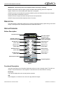
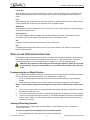
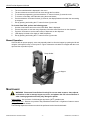
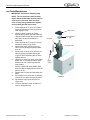
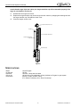
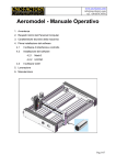
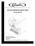
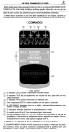
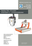
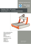
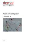
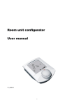
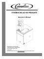
STARBUCKS UC100 PROGATE
Operator’s Manual
Release Date: January 24, 2008
Publication Number: 621054211OPR
Revision Date: April 07, 2014
Revision: B
Visit the Cornelius web site at www.cornelius.com for all your Literature needs.
The products, technical information, and instructions contained in this manual are subject to change
without notice. These instructions are not intended to cover all details or variations of the equipment,
nor to provide for every possible contingency in the installation, operation or maintenance of this
equipment. This manual assumes that the person(s) working on the equipment have been trained
and are skilled in working with electrical, plumbing, pneumatic, and mechanical equipment. It is
assumed that appropriate safety precautions are taken and that all local safety and construction
requirements are being met, in addition to the information contained in this manual.
This Product is warranted only as provided in Cornelius’ Commercial Warrant applicable to this Product and is subject to all of the restrictions and limitations contained in the Commercial Warranty.
Cornelius will not be responsible for any repair, replacement or other service required by or loss or
damage resulting from any of the following occurrences, including but not limited to, (1) other than
normal and proper use and normal service conditions with respect to the Product, (2) improper voltage, (3) inadequate wiring, (4) abuse, (5) accident, (6) alteration, (7) misuse, (8) neglect, (9) unauthorized repair or the failure to utilize suitably qualified and trained persons to perform service and/or
repair of the Product, (10) improper cleaning, (11) failure to follow installation, operating, cleaning or
maintenance instructions, (12) use of “non-authorized” parts (i.e., parts that are not 100% compatible
with the Product) which use voids the entire warranty, (13) Product parts in contact with water or the
product dispensed which are adversely impacted by changes in liquid scale or chemical composition.
Contact Information:
To inquire about current revisions of this and other documentation or for assistance with any Cornelius product contact:
www.cornelius.com
800-238-3600
Trademarks and Copyrights:
This document contains proprietary information and it may not be reproduced in any way without permission from Cornelius.
This document contains the original instructions for the unit described.
CORNELIUS INC
101 Regency Drive
Glendale Heights, IL
Tel: + 1 800-238-3600
Printed in U.S.A.
TABLE OF CONTENTS
Safety Instructions . . . . . . . . . . . . . . . . . . . . . . . . . . . . . . . . . . . . . . . . . . . . . . . . . . .
Read and Follow all Safety Instructions . . . . . . . . . . . . . . . . . . . . . . . . . . . . . . .
Recognize Safety Alerts . . . . . . . . . . . . . . . . . . . . . . . . . . . . . . . . . . . . . . . . . . .
Different Types of Alerts . . . . . . . . . . . . . . . . . . . . . . . . . . . . . . . . . . . . . . . . . . .
Safety Tips . . . . . . . . . . . . . . . . . . . . . . . . . . . . . . . . . . . . . . . . . . . . . . . . . . . . .
Qualified Service Personnel . . . . . . . . . . . . . . . . . . . . . . . . . . . . . . . . . . . . . . . .
CO2 (Carbon Dioxide) Warning . . . . . . . . . . . . . . . . . . . . . . . . . . . . . . . . . . . . .
Safety Precautions . . . . . . . . . . . . . . . . . . . . . . . . . . . . . . . . . . . . . . . . . . . . . . . . . .
Description . . . . . . . . . . . . . . . . . . . . . . . . . . . . . . . . . . . . . . . . . . . . . . . . . . . . . . . .
Keypad Overview . . . . . . . . . . . . . . . . . . . . . . . . . . . . . . . . . . . . . . . . . . . . . . . . . . .
Button Description . . . . . . . . . . . . . . . . . . . . . . . . . . . . . . . . . . . . . . . . . . . . . . . .
Functional Description . . . . . . . . . . . . . . . . . . . . . . . . . . . . . . . . . . . . . . . . . . . . .
PR (Prime) . . . . . . . . . . . . . . . . . . . . . . . . . . . . . . . . . . . . . . . . . . . . . . . . . . .
ICE . . . . . . . . . . . . . . . . . . . . . . . . . . . . . . . . . . . . . . . . . . . . . . . . . . . . . . . .
LOC (Lock) . . . . . . . . . . . . . . . . . . . . . . . . . . . . . . . . . . . . . . . . . . . . . . . . . .
FILL . . . . . . . . . . . . . . . . . . . . . . . . . . . . . . . . . . . . . . . . . . . . . . . . . . . . . . . .
ERR (Error) . . . . . . . . . . . . . . . . . . . . . . . . . . . . . . . . . . . . . . . . . . . . . . . . . .
FLAP (Flapper) . . . . . . . . . . . . . . . . . . . . . . . . . . . . . . . . . . . . . . . . . . . . . . .
E01 . . . . . . . . . . . . . . . . . . . . . . . . . . . . . . . . . . . . . . . . . . . . . . . . . . . . . . . .
E02 . . . . . . . . . . . . . . . . . . . . . . . . . . . . . . . . . . . . . . . . . . . . . . . . . . . . . . . .
Start-up and Operating Instructions . . . . . . . . . . . . . . . . . . . . . . . . . . . . . . . . . . . . .
Programming the Ice Weight Portion . . . . . . . . . . . . . . . . . . . . . . . . . . . . . . . . .
Viewing & Resetting Defaults: . . . . . . . . . . . . . . . . . . . . . . . . . . . . . . . . . . . . . . .
To view the Data Table, perform the following steps: . . . . . . . . . . . . . . . . . .
Manual Operation . . . . . . . . . . . . . . . . . . . . . . . . . . . . . . . . . . . . . . . . . . . . . . . .
Maintenance . . . . . . . . . . . . . . . . . . . . . . . . . . . . . . . . . . . . . . . . . . . . . . . . . . . . . . .
Daily (or as required) . . . . . . . . . . . . . . . . . . . . . . . . . . . . . . . . . . . . . . . . . . . . . .
Cleaning Exterior Surfaces . . . . . . . . . . . . . . . . . . . . . . . . . . . . . . . . . . . . . . . . .
Ice Chute Maintenance . . . . . . . . . . . . . . . . . . . . . . . . . . . . . . . . . . . . . . . . . . . .
Monthly Maintenance . . . . . . . . . . . . . . . . . . . . . . . . . . . . . . . . . . . . . . . . . . . . .
Cleaning Interior Surfaces . . . . . . . . . . . . . . . . . . . . . . . . . . . . . . . . . . . . . . .
Specifications . . . . . . . . . . . . . . . . . . . . . . . . . . . . . . . . . . . . . . . . . . . . . . . . . . . . . .
Troubleshooting . . . . . . . . . . . . . . . . . . . . . . . . . . . . . . . . . . . . . . . . . . . . . . . . . . . .
1
1
1
1
1
1
1
1
2
2
2
2
2
2
3
3
3
3
3
3
3
3
3
4
4
4
5
5
6
7
7
8
9
UC100 ProGate Operator’s Manual
SAFETY INSTRUCTIONS
Read and Follow all Safety Instructions
Read and follow all safety instructions in this manual and on the machine (decals, labels, and laminated
cards). Read and understand all applicable OSHA (Occupation Safety and Health Administration) safety
regulations before operating the machine.
Recognize Safety Alerts
This is the safety alert symbol. When you see it in this manual or on the machine be
alert to the potential of personal injury or damage to the machine.
Different Types of Alerts
There are 3 types of safety alerts:
DANGER — Indicates an immediate hazardous situation which if not avoided WILL result in
serious injury, death, or equipment damage.
WARNING — Indicates a potentially hazardous situation which, if not avoided, COULD result in
serious injury, death, or equipment damage.
CAUTION — Indicates a potentially hazardous situation which, if not avoided, MAY result in
minor or moderate injury or equipment damage.
Safety Tips
•
•
•
•
Carefully read all safety messages in this manual and safety signs on the machine.
Keep safety signs in good condition and replace missing or damaged safety signs.
Learn how to operate the machine and how to use the controls properly.
Do not let anyone operate the machine without proper training. This appliance is not intended for use
by very young children or infirm persons without supervision. Young children should be supervised to
ensure that they do not play with the appliance.
• Keep your machine in proper working condition and do not allow unauthorized modifications to the
machine.
Qualified Service Personnel
CAUTION — Only trained and certified electrical, plumbing and refrigeration technicians should
service this unit. ALL WIRING AND PLUMBING MUST CONFORM TO NATIONAL AND LOCAL
CODES.
CO2 (Carbon Dioxide) Warning
WARNING — CO2 Displaces Oxygen. Strict Attention must be observed in the prevention of
CO2 gas leaks in the entire CO2 and soft drink system. If a CO2 gas leak is suspected, particularly
in a small area, immediately ventilate the contaminated area before attempting to repair the leak.
Personnel exposed to high concentration of CO2 gas will experience tremors which are followed
rapidly by loss of consciousness.
SAFETY PRECAUTIONS
This ice dispenser has been specifically designed to provide protection against personal injury and
eliminate contamination of ice. To ensure continued protection and sanitation, observe the following:
© 2008-2014, Cornelius Inc.
-1-
Publication Number: 621054211OPR
UC100 ProGate Operator’s Manual
IMPORTANT: Disconnect power to the dispenser before servicing or cleaning.
NEVER: place hands inside of hopper or gate area without disconnecting power to the dispenser.
Agitator rotation occurs automatically when dispenser is energized!
ALWAYS: be sure the removable lid is properly installed to prevent unauthorized access to the hopper
interior and possible contamination of the ice.
ALWAYS: be sure the upper and lower front panels are securely fastened.
ALWAYS: keep area around the dispenser clean of ice cubes.
DESCRIPTION
The Undercounter ice dispenser solves your ice service needs with a sanitary, space saving, economical
design. It is designed to be manually filled with Ice-O-Matic half cube ice.
KEYPAD OVERVIEW
Button Description
Information Display
Green dot indicates
unit power is ON
“Shaken” product ice
portion side of keypad
“Blended” product ice
portion side of keypad
Blended Short ice
portion button
Shaken Short ice
portion button
Shaken Tall ice
portion button
Blended Tall ice
portion button
Shaken Grande
ice portion button
Blended Grande ice
portion button
Shaken Venti ice
portion button
Blended Venti ice
portion button
Manual Dispense Button
Programming Button
Figure 1
Functional Description
Just above the keypad is an information display that will show a code 2 through 4 letter. This code is to
notify the user the status/error of the dispenser. Listed below are the codes and their meaning:
PR (Prime)
This code will display when the unit has just been powered.
ICE
When displayed, ice levels are low or close to empty inside the hopper.
Publication Number: 621054211OPR
-2-
© 2008-2014, Cornelius Inc.
UC100 ProGate Operator’s Manual
LOC (Lock)
When displayed, check to make sure that ice bin covers, ice chute transition, piece ice flapper and ice
chute are attached properly. Once secured, push the “M” button on the keypad to return to dispense
mode.
FILL
When displayed, all ice has been consumed and needs to be replaced. Refill the ice bin. Close all ice bin
covers and push the “M” button on the keypad to return to dispense mode.
ERR (Error)
When displayed, a system fault has occurred. Push the “M” button on the keypad to reset the dispenser
and return to dispense mode.
FLAP (Flapper)
This code is displayed when the flapper has not made contact or not made correct contact with the
microswitch. Push the “M” button on the keypad to return to the dispense mode.
E01
Keypad pc board has failed its internal memory check. Call service.
E02
A keypad button has been held down or stuck for one minute. Push the “M” button on the keypad to
return to dispense mode.
START-UP AND OPERATING INSTRUCTIONS
Fill the hopper with ice and then push one of the “V” buttons on the keypad to dispense a large cup of ice.
Repeat this procedure every time the dispenser has run out of ice. This insures that the ice chute is
completely filled before use. If the dispenser fails to dispense ice, see troubleshooting guide.
CAUTION: Use caution to avoid spilling ice when filling the dispenser. Clean up any spilled
ice immediately. To prevent contamination of ice, the lid must be installed on the unit at all
times.
Programming the Ice Weight Portion
The ice weight portion setting is factory set for each portion size or keypad button. Follow the instructions
below to increase or decrease the amount of ice dispensed for a portion size.
1.
Press “P” and Blended Short (S) buttons simultaneously until SIZE displays on the information
display.
2.
Press and hold the desired size you wish to program until corresponding green LED flashes.
NOTE: The information display will now show the current value (in milliseconds) of that portion
size.
3.
4.
5.
Press the up or down button to increase/decrease the duration of dispense. Each press increases/
decreases the duration by 1ms.
Press the corresponding size button currently being programed until the green LED stops flashing.
To save the new programmed size, press the “P” and the Blended Short (S) buttons simultaneously
until the screen clears. If no action is taken within 60 seconds, dispense mode resumes and any
changes are not saved.
Viewing & Resetting Defaults:
The controller has four default tables contained within it. These tables are: “USA”, “International”,
“Custom” and “Data”.
To view or program the current table perform the following steps:
1.
Press and hold the “P” button and the “M” button simultaneously.
© 2008-2014, Cornelius Inc.
-3-
Publication Number: 621054211OPR
UC100 ProGate Operator’s Manual
2.
3.
4.
5.
6.
7.
The current default table is displayed in the menu.
The arrow buttons can now be used to move through the four tables.
To exit without programming, press and hold the “P” button for three (3) seconds to exit.
To reset to a new table, select the table using the arrow buttons.
Press and hold the “M” button for three (3) seconds, the display flashes twice when the new setting
is accepted.
Exit by pressing and holding the “P” button for three (3) seconds.
To view the Data Table, perform the following steps:
1.
Use the arrow buttons and move to the DATA table. Data is displayed.
2.
Press a size button to see how many dispenses of that size have been done on the dispenser.
3.
Press the “M” button to see the total number of dispenses on the dispenser.
4.
LED display is limited to four digits or “9999” dispenses.
5.
Exit by pressing and holding the “P” button for three (3) seconds.
Manual Operation
If the unit fails to operate properly, users may manually obtain ice from the hopper by opening the lid and
using the “size specific scoop” to scoop out ice. Figure 2 shows the unit with the ice hopper with the cover
open and the cup holder in place.
Scoop Holder
Ice Hopper
Figure 2
MAINTENANCE
WARNING: Disconnect Power Before Cleaning! Do not use metal scrapers, sharp objects,
or abrasives on the ice storage hopper, top cover, and agitator disk. Do not use solvents or
other cleaning agents because they may damage the plastic.
Soap solution – Use a mixture of mild detergent and warm (100oF) potable water.
Sanitizing solution – Dissolve one packet of Kay-5 Sanitizer/Cleaner into 2-1/2 gallons of water to ensure
100 ppm of available chlorine.
The following dispenser maintenance should be performed at the intervals indicated:.
Publication Number: 621054211OPR
-4-
© 2008-2014, Cornelius Inc.
UC100 ProGate Operator’s Manual
Daily (or as required)
Remove foreign material from vending area drip tray to prevent drain blockage. Clean vending area.
Check for proper water drainage from the vending area drip tray.
Cleaning Exterior Surfaces
IMPORTANT: Perform the following daily.
1.
2.
Remove the cup rest from drip tray.
Wash the drip tray with soap solution. Rinse with potable water and allow solution to run down the
drain.
CAUTION — Do not pour hot coffee or other hot liquids into the drip tray. This causes the plastic
drip tray to develop cracks and leaks.
3.
4.
Wash cup rest with soap solution and rinse in potable water. Install the cup rest into the drip tray.
Clean all exterior surfaces with soap solution and rinse with potable water.
© 2008-2014, Cornelius Inc.
-5-
Publication Number: 621054211OPR
UC100 ProGate Operator’s Manual
Ice Chute Maintenance
IMPORTANT: Perform the following daily.
NOTE: The ice chute has a built in safety
feature which disables the unit when the ice
chute cover is removed. If the ice chute
cover is not properly installed, the agitator
and ice chute gate will not function.
1.
Press and hold the “P” and “UP” buttons
for five (5) seconds to enter purge mode.
LED displays “Purg”.
2.
Holding a large container or bucket
beneath the ice chute, press and hold the
“Manual” button to open the ice gate. Gate
stays open as long as the button is
depressed.
3.
Press and hold the “P” button for five (5)
seconds to exit the purge mode.
4.
Remove the finger guard from the ice
chute cover by sliding the guard upward
then out.
5.
Remove the ice chute cover from the ice
chute by pushing the black locking tab
(Figure 4) back and sliding the ice chute
upward and out.
6.
Wash the ice chute, ice chute cover, finger
guard, and ice level flapper with a nylon
bristle brush and a clean rag using the
soap solution.
7.
Rinse the parts with clean potable water
then rinse with sanitizing solution. Allow all
parts to air dry.
8.
Replace the ice chute and slide down into
place.
9.
If the agitator or ice chute are not working,
remove the ice chute cover and replace it.
10. Reinstall the finger guard onto the ice
chute cover.
11. If ERR is displayed, press “M” button to
return to dispense mode.
Publication Number: 621054211OPR
-6-
Tower Cover
Auger Transition
Cap
Ice Chute
Ice Chute Cover
Finger
Guard
Figure 3
© 2008-2014, Cornelius Inc.
UC100 ProGate Operator’s Manual
Ice Chute Cover
Locking Tab
Ice Chute Cover
Figure 4
Monthly Maintenance
Clean and sanitize the hopper interior and auger assembly.
Cleaning Interior Surfaces
CAUTION: When pouring liquids into the hopper, do not exceed the rate of 1/2 gallon per
minute.
IMPORTANT: Perform the following procedure at least once a month.
1.
2.
3.
4.
5.
Open right hand hopper cover and remove all ice from hopper.
Remove the agitator disk and agitator assembly.
Remove the tower cover. (See Figure 5.)
Move the retaining bail to the rear of the tower. This allows removal of the auger transition cap.
The auger tubes are in two halves. Slowly pull up and remove front half of auger tube, then the
back half of the auger tube.
6.
Grasp the ice auger by the shaft end and slowly pull it up and out. It may be necessary to lean the
auger forward during removal to avoid hitting the ceiling.
7.
Remove the front panel of the cabinet below the hopper, this provides access to the lower auger
drive area and the passage between the hopper and the auger for cleaning.
8.
Using the previously prepared soap solution to clean the hopper cover, agitator disk and agitator
assembly, interior of the hopper, both halves of the ice chute, auger, auger tubes, and the lower
auger area of the auger housing. Thoroughly rinse all parts with potable water. Spray all
components with sanitizing solution and allow to air dry.
9.
Reassemble the agitator assembly and disc into the hopper. Make certain that the retaining screw
is tight.
10. Reinstall the auger.
NOTE: The bottom of the auger has a depression in the shape of a D. When replacing the auger,
it will be necessary to rotate the auger after insertion in the tube to engage the motor shaft. Make
© 2008-2014, Cornelius Inc.
-7-
Publication Number: 621054211OPR
UC100 ProGate Operator’s Manual
certain that the auger slips into it drive pin. Auger transition cap will not assemble properly if the
auger is not seated on its drive pin.
11.
12.
Reinstall the two auger tube halves.
Replace the auger transition cap onto the auger and lock it down by snapping the retaining bail onto
the auger transition cap. Reinstall the tower cover.
13. Close the hopper access cover.
AUGER TRANSITION CAP
AUGER
AUGER TUBE BACK
AUGER TUBE FRONT
RETAINING BAIL
Figure 5
SPECIFICATIONS
Model:
Ice Storage:
Electrical:
CO2 or Air:
Dimensions:
UC100 Progate
100 lbs
120/1/60, 3 amps total unit draw
100 psi max to unit regulated to 65 psi (4.48 bar) to Progate ice gate system
24-3/16 in. Wide; 30-3/8 in. Deep
27 in. Below Countertop; 28 in. Above Countertop
Publication Number: 621054211OPR
-8-
© 2008-2014, Cornelius Inc.
UC100 ProGate Operator’s Manual
TROUBLESHOOTING
IMPORTANT: Only qualified personnel should service internal components or electrical wiring.
WARNING: If repairs are to be made to the CO2 or air system, stop dispensing, shut off the
CO2 or air supply, then relieve the system pressure before proceeding. If repairs are to be
made to the ice dispensing system, make sure electrical power is disconnected from the
unit.
Trouble
Probable Cause
Remedy
NOTE: Should your unit fail to operate properly, check that there is power to the unit and that the
hopper contains ice. If the unit does not dispense, check the following chart under the appropriate
symptom(s) to aid in locating the defect.
BLOWN FUSE OR
A. Short circuit in wiring (115V circuit).
A. Contact service agent.
CIRCUIT BREAKER.
B. Defective agitator motor.
B. Contact service agent.
SLUSHY ICE. WATER IN A. Blocked drain.
A. Open-up/flush out drain.
HOPPER
B. Unit not level.
B. Level unit.
C. Poor ice quality due to water quality or C. Contact service agent. For Icemaker
ice maker problems.
problems, consult icemaker service
agent.
D. Improper use of flaked ice.
D. Replaced flaked ice with cube style ice.
NO ICE DISPENSED
A. Insufficient ice supply in ice bin.
A. Replenish ice supply as required.
B. Ice in ice bin bridged (stuck together). B. Gently tap on ice to break it loose.
C. No electrical power to dispenser.
C. Plug in dispenser power cord, or check
fuse or circuit breaker.
D. Insufficient or no CO2 or air supply to D. Restore CO2 or air supply to dispenser.
dispenser.
E. Ice chute cover not properly installed. E. Make sure that cover is “snapped” into
place.
F. Defective interlock switches.
F. Contact service agent.
G. Defective interlock relay.
G. Contact service agent.
H. Defective 24V transformer.
H. Contact service agent.
I. Defective keypad.
I. Contact service agent.
J. Defective ice gate cylinder.
J. Contact service agent.
K. Defective ice gate solenoid valve.
K. Contact service agent.
L. Defective agitation timer board.
L. Contact service agent.
M. Defective agitator motor start capacitor.M. Contact service agent.
N. Hopper covers not properly installed/ N. Make sure covers are in place and
closed.
closed.
A. Insufficient or no CO2 or air supply to A. Restore CO2 or air supply to dispenser.
NO ICE DISPENSED
FROM MANUAL ICE
dispenser.
DISPENSE
B. Defective 24VAC transformer.
B. Contact service agent.
PUSHBUTTON SWITCH
C. Defective keypad.
C. Contact service agent.
D. Defective agitator motor or start capac- D. Contact service agent.
itor.
E. Defective ice gate cylinder.
E. Contact service agent.
ICE DISPENSING
A. Defective ice gate cylinder.
A. Contact service agent.
DURING AUTOMATIC
AGITATION
B. Defective ice gate solenoid valve.
B. Contact service agent.
C. Defective keypad.
C. Contact service agent.
© 2008-2014, Cornelius Inc.
-9-
Publication Number: 621054211OPR
UC100 ProGate Operator’s Manual
Publication Number: 621054211OPR
- 10 -
© 2008-2014, Cornelius Inc.
Cornelius Inc.
www.cornelius.com