1
®
2N NETSTAR
Communication switch
Configuration tool
Version
2.6.0
www.2n.cz
The 2N TELEKOMUNIKACE joint-stock company is a Czech manufacturer and supplier of
telecommunications equipment.
The product family developed by 2N TELEKOMUNIKACE a.s. includes GSM gateways,
private branch exchanges (PBX), and door and lift communicators. 2N TELEKOMUNIKACE
a.s. has been ranked among the Czech top companies for years and represented a
symbol of stability and prosperity on the telecommunications market for almost two
decades. At present, we export our products into over 120 countries worldwide and have
exclusive distributors on all continents.
2N® is a registered trademark of 2N TELEKOMUNIKACE a.s.. Any product and/or other
names mentioned herein are registered trademarks and/or trademarks or brands
protected by law.
2N TELEKOMUNIKACE administers the FAQ database to help you quickly find information
and to answer your questions about 2N products and services. On faq.2n.cz you can find
information regarding products adjustment and instructions for optimum use and
procedures “What to do if...”.
Declaration of Conformity
2N TELEKOMUNIKACE hereby declares that the 2N® SIM Star product complies with all
basic requirements and other relevant provisions of the 1999/5/EC directive. For the full
wording of the Declaration of Conformity see the CD-ROM enclosed and at www.2n.cz.
The 2N TELEKOMUNIKACE company is the holder of the ISO 9001:2000 certificate. All
development, production and distribution processes of the company are managed by this
standard and guarantee a high quality, technical level and professional aspect of all our
products.
Table of Content
1 Basic Information ............................................................................................................ 5
1.1 About Help ..................................................................................................................................................................5
1.2 About application.........................................................................................................................................................5
1.3 Connection to the PbX .................................................................................................................................................6
1.4 Configuration menu ................................................................................................................................................... 10
1.5 PbX activation ........................................................................................................................................................... 13
2 Hardware....................................................................................................................... 17
2.1 Hardware profiles ...................................................................................................................................................... 17
2.2 Boards ....................................................................................................................................................................... 17
2.3 Synchronization ......................................................................................................................................................... 20
2.4 Board list ................................................................................................................................................................... 21
2.5 Port list ...................................................................................................................................................................... 21
3 Virtual ports .................................................................................................................. 22
3.1 BRI and PRI virtual ports ........................................................................................................................................... 22
3.2 Cornet virtual port...................................................................................................................................................... 26
3.3 ASL virtual port ......................................................................................................................................................... 27
3.4 CO virtual port ........................................................................................................................................................... 29
3.5 GSM virtual port ........................................................................................................................................................ 30
3.6 SIP virtual ports ......................................................................................................................................................... 33
3.7 Virtual port options .................................................................................................................................................... 38
4 SIM cards ...................................................................................................................... 43
4.1 SIM cards .................................................................................................................................................................. 43
5 Network......................................................................................................................... 44
5.1 Network interface ...................................................................................................................................................... 44
5.2 Services Setting ......................................................................................................................................................... 44
6 Global data .................................................................................................................... 52
6.1 Global parameters ...................................................................................................................................................... 52
6.2 Localization ............................................................................................................................................................... 53
6.3 Licences .................................................................................................................................................................... 54
6.4 Language packages .................................................................................................................................................... 55
6.5 Services ..................................................................................................................................................................... 56
6.6 Progress tones ............................................................................................................................................................ 58
6.7 Ring tones.................................................................................................................................................................. 62
6.8 Time parameters ........................................................................................................................................................ 63
6.9 Autoclip parameters ................................................................................................................................................... 66
6.10 Assistant .................................................................................................................................................................. 67
7 Routing.......................................................................................................................... 69
7.1 Routers ...................................................................................................................................................................... 69
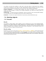
7.2 Routing objects .......................................................................................................................................................... 74
7.3 Identification tab ........................................................................................................................................................ 93
7.4 Autoclip routers ......................................................................................................................................................... 95
8 Users ............................................................................................................................. 98
8.1 Users and Groups ....................................................................................................................................................... 98
8.2 User rights ............................................................................................................................................................... 104
8.3 Station types ............................................................................................................................................................ 106
8.4 Stations.................................................................................................................................................................... 106
8.5 Phone books ............................................................................................................................................................ 109
9 Setting up the Properties Tab ...................................................................................... 113
9.1 Setting the properties tab .......................................................................................................................................... 113
About Help
1.1
1 Basic Information
1.1 About Help
The document serves as Help and Manual for the configuration of the communication system 2N
Netstar by program NsAdmin. 2N reserves the right to modifications.
1.2 About application
About application
NsAdmin is a configuration tool that is used to configure 2N Netstar communication system, version
2. The application is designed for a x86 platform using the WINDOWS 2000/XP operating system
connected within a network with 2N Netstar. It is controlled by a mouse and, as a secondary input,
by keyboard. NsAdmin uses TCP connection or modem and communicates with 2N Netstar basicly via
port 6992.
Necessary condition for using this configuration tool under operating system Windows XP is installed
service pack 2 and Framework v.3. Wihout these components program doesn't work.
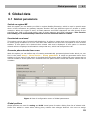
Main menu of the configuration tool
Until running configuration tool is displayed window for configuration particular connections to PbXs.
In this window you can also analyse old traces and start up this help. Main menu offers following
options:
Administrator
Settings – It opens dialogue with global settings of the configuration tool.
Language – Here you can choose one of supported languages.
Exit – It is used for exiting configuration tool.
Trace – In this menu you aren't able to view online trace from your PbX, but you can view previously
saved traces.
Load trace from file
Add trace from file
Trace analyse – It opens window for basic analyse of the trace.
Help – With this option you can start this help in dependence on chosen language.
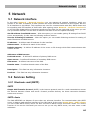
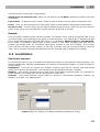
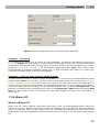
Global settings of the configuration tool
This dialogue includes three parts with following parameters:
XML script
Type of trace – Within this section you can define range of displayed xml trace of the configuration
tool. It doesn't set trace of the PbX.
5
Connection to the PbX
1.3
Size of indent – It defines size of indent for xml trace.
Colours
Setting colours of ports – Here you can define colour of each type of the virtual port or completely
disable this function.
Setting colours of tabs – Here you can define background color for tabs or completely disable this
function.
Setting colours of stations – Here you can define colour of each type of the station (SIP, external,
...) or completely disable this function.
Setting colours of logins – Here you can define colour of each type of the user login or completely
disable this function.
View – This part enables displaying of information which can be used during trace analyse using
database.
Show name of actual window – If this option is checked name of actual window is shown on the
right bottom corner.
Show object Id – If this option is checked Id of actual object is shown on the right bottom corner.
For using set configuration you have to use button OK and for exiting dialogue without saving
changes you have to use button Cancel.
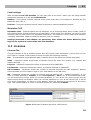
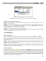
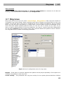
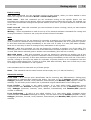
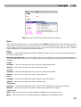
1.3 Connection to the PbX
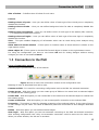
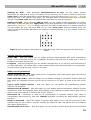
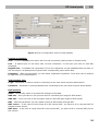
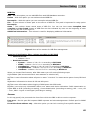
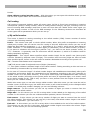
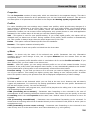
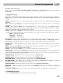
Icons of connection section
Following figure presents all icons of this section.
Figure 1 View of icons from connection section of the configuration tool.
Meaning of icons is described from left to right.
Connect to PbX – It is used for connecting configuration tool to the PbX via selected connection.
Create group – With this option you can create group of PbXs on the same level as selected object
or nested into the existing group.
Create PbX – With this option you can create PbX on the same level as selected object or nested into
the existing group.
Create connection – With this option you can create specific connection to the selected PbX.
Properties – This option is used for changing properties of the selected object. In the case of group
ou can change only its name. For cases of PbXs and particular connections is this dialogue described
below.
Delete – With this option you can delete selected object.
Auto login – With this option you can set automatic connecting to the PbX via selected connection
after starting configuration tool. Only one automatic connection could be active at the same time.
When you select another, the old one is canceled.
6
Connection to the PbX
1.3
Cancel auto login – With this option you can cancel automatic connection. You haven't to select
concrete object before.
Except these options are within context menu another options with following meaning:
Import PbX structure – With this option you can import predefined PbX structure, which is
described below.
Export PbX structure – With this option you can export actual PbX structure, which you can later
use for work from another computer.
Import database – This option is used for importing database of actual PbX in offline mode only. In
online mode is always used database from the PbX.
Export database – This option is used for exporting database of actual PbX and is also used only in
offline mode.
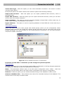
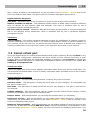
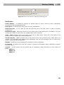
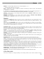
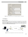
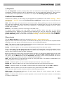
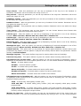
Connection hierarchy
Within this menu you can create groups and nested groups, where you can consequently create
particular PbXs. PbX you can create also without groups, but when you use more PbX, then is this
sortage advantage. For concrete PbXs you can create particular connections. You can select between
TCP/IP and modem connection.
Figure 2 View of possible structure of connections.
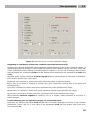
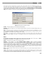
Properties of each PbX or connection you can change via option Properties.
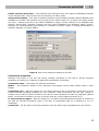
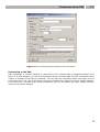
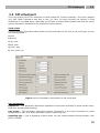
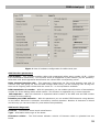
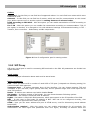
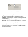
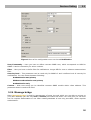
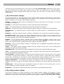
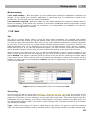
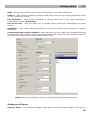
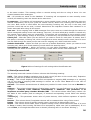
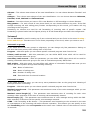
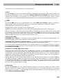
PbX properties
Dialogue from figure 3 you can see during creating PbX in configuration or during changing properties
of existing one. Meaning of partucular parameters is following:
Name – This parameter defines name of the PbX within configuration menu. Folder – With this
parameter you can define path to the folder where configuration tool saves its configuration.
Autosave – With this option you can enable automatic saving of the database in offline mode.
Autosave database after – This parametr sets interval for automatic backup of the database. This
function can be used only for offline mode.
7
Connection to the PbX
1.3
Delete autosave item older – This parametr sets maximum time for keeping old database backups
in the storage folder. This function can be used only for offline mode.
Autosynchronization – This option enables automatic synchronization between offline database and
database in the PbX. This function can be used only for offline mode. If it is active then these modes
are used : Loading from PbX if the offline database is empty. Screen changes if the database was
already synchronized, identifier matches and the option Database from autosave wasn't chosen.
Dialogue for synchronization type selection is invoked in all other events. If autosynchronization is
inactive, dialogue is invoked always.
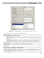
Figure 3 View of the properties setting of the PbX.
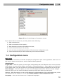
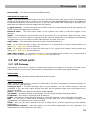
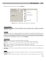
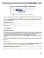
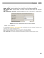
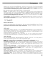
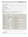
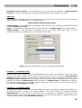
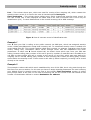
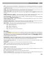
Connection properties
Dialogue from figure 4 you can see during creating connection to the PbX or during changing
properties of existing one. Meaning of partucular parameters is following:
Connection name – Sets name for selected connection.
Modes – This parametr defines if this connection will support online mode, offline mode or both
modes.
Connection type – With this option you can define concrete type of connection to the PbX. You can
choose between interfaces installed on your computer. Most connections will use type TCP/IP or
modem. In the case of TCP/IP connection you have to enter IP address of CPU and used port (default
6992). In the case of modem you have to choose that one, which supports protocol X.75.
If unsuccessful try again – With this option you can define interval between attempts to connect to
the PbX via selected connection type in the case of inaccessible PbX (it is switched of or it is
restarting).
Connect as – For the case of secured connection you can define login and password in this section.
8
Connection to the PbX
1.3
Figure 4 View of the properties setting of the connection.
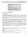
Connecting to the PbX
After automatic or manual initiation of connecting to the selected PbX is displayed dialogue from
figure 5. In this dialogue you can find information about connected PbX and also information about
version of firmware of the PbX (if detected). You can also see information about last knoen error of
connection and in the case of automatic connection attemps also remaining time to another attempt.
If you want to try connect before timeout expiration, you can use button Try again. Button Cancel is
used for leaving this dialogue.
9
Configuration menu
1.4
Figure 5 View of the dialogue of connection course.
If you aren't able to connect to your PbX, please check following:
1) PbX is switched on;
2) PbX is connected to the network;
3) both sides have the same IP address and port;
4) used communication port is opened;
5) you are using corresponding versions of firmware and configuration tool;
6) used communication port isn't blocked by your antivirus software;
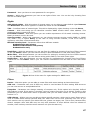
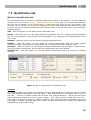
1.4 Configuration menu
Main menu
After succesful connection to the PbX is displayed configuration part of the application. Main menu of
this view is shown on the figure 1 and it contains following options:
Administrator
Logout PbX – With this option you can logout configuration tool from PbX and return to the previous
menu where you can choose another connection. Connect/Disconnect – These options are used only
in the offline mode. You can use them for connecting and disconnecting configuration tool to the PbX.
Save changes – With this option you can save all changes made since last save. Undo changes –
With this option you can cancel all changes made since last save within concrete menu.
Settings – With this option you can invoke dialogue for global settings of the configuration tool, which
was described in the chapter 1.2 in the part Global settings of the configuration tool.
Language – Here you can choose one of supported languages.
10
Configuration menu
1.4
Exit – It is used for exiting configuration tool.
Trace
Load trace from file – This option is used for loading concrete saved trace from the file. Old trace is
cleared.
Add trace from file – This option is used for adding another saved trace to actual one. It can
connect more traces to one, which you can analyse easily.
Save trace to file – This option is used for saving actual online trace to the file. Configuration tool
always saves whole trace independently of actualy used filter.
Trace analyse – It opens window for basic analyse of the trace.
PbX
Upgrade – With this option you can invoke dialogue for firmware upgrade. After choosing file with
firmware is it uploaded into the PbX and decompressed. After following restart is used new firmware.
Import logs from PbX – With this option you can easily reach most important files in the space of
the PbX without using another aplications like WinSCP. After choosing concrete folder are downloaded
config.db, aoc.db, whole content of the folders /data/netstar/log and /var/log. These data aren't
removed from PbX.
Service mode – With this option you can switch PbX to the service mode, when you can handle with
all boards except CPU. After using this option is it changed to option Cancel service mode.
Restart PbX – With this option you can invoke restart of actual connected PbX.
Wizards
Activation wizard – This wizard is in detail described in the next chapter PbX activation in steps.
Import/export company structure – This option invokes dialogue for import or export company
structure. Csv and Xml files are supported.
Help – With this option you can start this help in dependence on chosen language.
Figure 1 View of the main menu of the configuration tool.
Figure 1 shows also all icons of this menu. Meaning of icons is described from left to right.
Logout PbX – With this icon you can logout configuration tool from PbX and return to the previous
menu where you can choose another connection. Connect/Disconnect – These icons are displayed
only in the offline mode. You can use them for connecting and disconnecting configuration tool to the
PbX.
Save changes – With this icon you can save all changes made since last save.
Undo changes – With this icon you can cancel all changes made since last save within concrete
menu.
Language – Particular flags are used for selecting concrete language of the configuration tool.
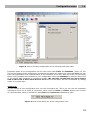
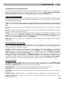
Windows
On the left side of the configuration tool you can find TreeView, where you can choose menu which
you want to configurate. Selected menu is then displayed on the right side and it is mostly divided
into two windows. First one for selecting concrete object of selected type and second one for setting
up this concrete object. All three parts you can see on following figure.
11
Configuration menu
1.4
Figure 2 View of dividing configuration tool to windows and menu tabs.
Important parts of the configuration tool are also menu tabs Trace and Database, which you can
find on the bottom of the configuration tool above the status bar. Within the menu tab Trace you can
trace call signalization and communication at all interfaces of the PbX. With this trace you can easily
detect main problems and mistakes in your configuration. Menu tab Database is used for direct view
to the stored data (depends on connection mode). We strongly recommend you don't change
data in this view if don't know how to do it! View to this menu tab can be disabled by setting
rights of concrete login.
Status bar
On the bottom of this configuration tool you can find status bar. There you can see two important
information. First one is mode of connection, which could be online or offline. Second one is name
of connected PbX, which is divided into parts PbX and connection separated by dash.
Figure 3 View of the status bar of the configuration tool.
12
PbX activation
1.5
1.5 PbX activation
What do you need?
To activate and set up 2N Netstar you need the 2N Netstar itself, x86 computer running supported
operating system Windows, keyboard and mouse. PbX have to be connected in the network with 2N
Netstar. It is also necessary to display the redirected standard input and output of 2N Netstar on your
PC's console. For this you need a six-core cable with a six-pin connector RJ-12 on one end and a
serial connector on the other end. This cable is supplied as standard equipment. As a console, you
may use, for example application "Tera Term Pro" or any other functional console. It is possible to
work in "Hyperterminal", but longer listings are interlaid.
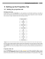
Step 1: IP address setting
Prior to starting the configuration you need to set up the IP address of the communication system
and provide network communication between the system and the computer, from which the system
will be configured. The IP address can be set up using a serial console or by connecting to a default IP
address 192.168.100.100. Communication with 2N Netstar can be on-line or off-line. Console has to
be set according to following table:
Speed
Bits
Parity
Stop bits
Flow control
115200
8
None
1
None
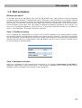
Step 2: Hardware activation
After first connection to the selected PbX according to the chapter Connecting to the PbX is
displayed configuration wizard from figure 1. This wizard is displayed only if PbX has new empty
database (wasn't preconfigured according to your demands).
13
PbX activation
1.5
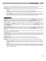
Figure 1 View of dialog box of wizard for hardware configuration.
If wizard was displayed, in this step you are able to define basic configuration of BRI virtual ports.
This setting can be changed at any time and if you aren't sure how to set it, you can go to another
step via button Next. After it begins configuration tool (in cooperation with PbX) to detect used
hardware, as you can see on figure 2.
Figure 2 View of the wizard during hardware detection.
14
PbX activation
1.5
Detected aren't only boards in the basic case, but also in connected extenderes. As soon as is
hardware detection finished, are created virtual ports for all detected ports (except VoIP boards).
After it will be your PbX ready for other configuration. Active hardware is signallized by LED diods.
Each board has to light green, except GSM board which doesn't have any LED diod for signalling of
board state. However functional GSM board id indicated by diods of its ports. After first startup as
well as after each firmware upgrade for the PbX is updated also firmware of GSM boards. This action
takes some time and that's why this boards can be activated slowly than others.
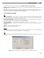
Step 3: Localization setting
Another important step of first configuration is localization determination. In this step you can define
parameters displayed on figure 3 and described in the chapter Localization. In addition you are able
to add your own language package, with your texts and progress tones. In the PbX you can always
found two installed language packages – Czech and English.
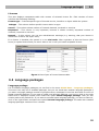
Figure 3 View of the wizard during localization determination.
Step 4: Creation of the stations
In this step of configuration wizard you can automatically create stations. Generated stations are
divided into three groups – analog, SIP and Cornet stations. Analog stations are used for ASL virtual
ports. SIP stations are used for connection of VoIP terminals supporting SIP signalling and are
assigned to the SIP proxy terminals. Cornet stations are used for system phones StarPoint, which are
connected to the Cornet virtual ports. For each group you can define phone number of the first
station and count of generated stations (every other station has number increased by one). Stations
are after creation assigned to the ports according to their types (if it is possible).
If you don't want to create stations automatically, you can also import company structure from
prepared file in one of supported formats – xml or csv. This way you can create relatively
complicated company structure including logins and more stations for specific users.
If you neither want to automatically create stations nor to import company structure, you can go to
another step via button Next by selected option Don't create anything.
15
PbX activation
1.5
Figure 4 View of the wizard for creating stations or for import of company structure.
Step 5: Creation of the routers
Last step of this wizard is used for routers creation. Routers are objects used for call or SMS routing
through the PbX from one port to another. Wizard offers some default sets of routers, which are
sufficient for basic call routing. If you have some special demands for routing, it stands to reason that
you can this default router also setup alone and extend it by another routers and rules. Created
default routers are also automatically filled with services, stations and users.
16
Hardware profiles
2.1
2 Hardware
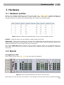
2.1 Hardware profiles
Setting up of hardware profiles you can find in the menu HW – HW profiles. With this setting you
can use your system more efficiently in some specific cases. This menu contains five different
hardware profiles. Its benefites and disadvantages are evident from following table.
Table 1 Shows benefits and disadvantages of each of five hardware profiles.
Enabled – With this option you can disable or enable using of this rack.
HW profile – After profile choosing you have to save configuration to the PbX and it will be set to
service regime and back to bring changes in effect. It is made because different hardware profiles use
different frequencies on bus in basic case and in extenders.
The column Delic Bus shows maximal count of digital channels, which can be allocate within the
basic case. From this value you have to subtract four channels which are allocated for extenders
connection.
2.2 Boards
Arrangement of HW
After clicking on the menu HW – Rack the rack fitting is displayed.
Figure 1 View of instaled boards of the PbX in the main case.
With buttons on the left side of the PbX you can change view from main case to selected extender.
17
Boards
2.2
After clicking on the right mouse button within the view of boards are available following options:
Add board – This option can be used only when context menu was invoked on free position of the
case (without any board). You can add board which is detected or your own from the list of supported
boards for this possition.
Remove board – This option is used for removing selected board. If this board has assigned virtual
ports, you can remove them also or retain.
Migrate virtual port/resource – This option can be used only when context menu was invoked on
some port. It starts dialogue box for virtual ports substitution.
Synchronize with detected – With this option you can synchronize actual case or extender with
detected boards of the PbX. If some board have to be removed from actual database, you have to
confirm it.
Expert menu – This option is used for access to advanced functions for case, board or virtual port.
Particular functions of this section are described below.
Expert menu – Virtual port
Assign virtual port/resource – This option assigns existing virtual port to the physic port. Virtual
port is selected from the list.
Create virtual port/resource – This option can be used only on physic ports without any assigned
virtual ports. New virtual port is automatically assigned to this physic port.
Remove virtual port/resource – With this option you can remove virtual port from concrete physic
port. This virtual port isn't deleted and is ready for another use including all its settings (routing,
assigned stations, ...). Name of this virtual port is changed from XXX to UnassignedXXX.
Delete virtual port/resource – With this option you can remove and permanent delete virtual port.
Such virtual port you aren't able to use later.
Regenerate name – With this option you can change name of concrete virtual port according to its
physic port.
Expert menu – Board and Case
Create virtual ports/resources – With this option you can create virtual ports for all physic ports
of the board or case at once. "All" means all physic ports without assigned virtual port.
Remove virtual ports/resources – With this option you can remove all virtual ports of the board or
case at once. These virtual ports aren't deleted and can be used later including their settings. Names
of these virtual ports are changed from XXX to UnassignedXXX.
Delete virtual ports/resources – With this option you can delete all virtual ports of the board or
case at once. These virtual ports can't be used anymore. Regenerate unchanged names – With
this option you can change all unchanged names of virtual ports of the board or case according to
theirs physic ports.
Regenerate all names – With this option you can change names of all virtual ports of the board or
case according to theirs physic ports.
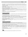
Board
Following figure shows all possible states of signalization on ports of the board.
18
Boards
2.2
Figure 2 View of analog board with all possible states of signalization.
Cross
Green – Physic port with assigned virtual port.
Yellow – Physic port with assigned virtual port and active call (or call establishment).
Earphone
Green – Physic port with assigned virtual port and assigned station.
Yellow – Physic port with assigned virtual port, assigned station and active call (or call
establishment).
Exclamation
Yellow – Physic port without assigned virtual port or physic port without detected state.
Red – Hardware error signalling. For example insufficient signal level for GSM, GSM port without SIM
card, ISDN virtual port with deactivated L1 or L2 (adjustable), ...
Tab Board
Below view of case is displayed tab Board, which is divided into two parts. Upper one shows basic
information about selected board. Meaning of parametres of this section is following:
Position – Number of board position within case as described below.
Type – Type of configured board.
Enabled – With this option you can disable selected board. This function can be used for example for
changing SIM cards without switching off whole PbX.
State – Actual state of the board. Here you can find for example information that configured board
doesn't match to detected.
Detected – In this section you can find detected parameters of the board.
Type – Type of detected board on selected position.
Serial number – Serial number of detected board on selected position.
MAC address – MAC address of detected board on selected position.
Under this part is window with list of ports of selected board. Meaning of particular columns of this list
is explained in the chapter Port list.
19
Synchronization
2.3
Tab Virtual port
Tab Virtual port is used for easier setting up of virtual ports. In this tab you can set up all
parameters of virtual ports and simultaneously see displayed screen of case. Setting of parameters of
virtual ports is described in chapter 3 according to type of stack.
Addressing
The position of each board is specified in the format R : C : B and the position of a port in the format
R : C : B : P. Meaning of each character is following: R – Number of the rack; C – Number of the
case in the rack; B – Number of the board in the case; P – Number of the port on the board;
Currently R takes the value of 0. C takes the value of 1 to 5. Basic case has the number 1, the first
extender number 2 up to the fourth extender with number 5. The positions of the boards (number B)
in the basic case are numbered from left to the right from 1 to 14. Positions in extender are
numbered from 1 to 12. First positions in the main case and in the extender is always reserved for
CPU board. At positions 0:1:2 to 0:1:4 can be only the boards 1x/2x/4x ISDN PRI (with or without
Zarlink) or Surf Ethernet. The position 0:1:5 is reserved for the Switch board which contains digital
switching array.
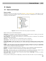
2.3 Synchronization
After connecting to the public or private ISDN network it is necessary to set up at least one port for
synchronization. In the menu HW – Synchronization there are two fields. The left one contains all
digital carriers, which can be ideally used for synchronization, it means all PRI and BRI carriers in TE
mode. The right field contains list of carriers, which are used for synchronization.
Figure 1 View of the menu for assigning synchronization ports and their priority.
Using buttons Right and Left you can move virtual ports from one field to another and ensure so
relevant synchronization sources for the PbX.
You can use the Up and Down buttons to shift the selected port, which changes the priority of the
selection of ports for synchronization – the port listed as first position has the highest priority (255).
Every other carrier has lower priority (254, 253, ..). After new assigment is carrier always placed to
the last position (position with the lowest priority). In the case of loss of synchronization a port with a
lower priority will be selected automatically. Upon restoring the synchronization it will return
automatically to the port with the highest priority.
20
Board list
2.4
2.4 Board list
This overview you can find in the menu Hardware – Board list. Within this menu is displayed list of
boards, which are physically present in the PbX. Boards list is displayed in four columns with following
meaning:
Address – It shows physical board address within the PbX according to the chapter Addressing.
Type – It shows board type.
Serial number – It shows board serial number, which was burned at production.
MAC address – It shows board MAC address.
2.5 Port list
This overview you can find in the menu Hardware – Port list. Within this menu are displayed all
physic ports sorted by address. List of physic ports consists of six columns with following meaning:
HW Address – It shows physical board address within the PbX according to the chapter Addressing.
Board – It shows type of the board for each physic port.
Virtual port – It shows complete name of the carrier, which is aasigned to specific physic port.
Stack – It shows type of assigned carrier (DSS1, ASL, CO, ...).
Station – It shows list of stations, which are assigned to the carrier of specific physic port.
User – It shows users of assigned stations for each physic port.
State – It shows actual state for each port.
Description – Supplementary information.
21
BRI and PRI virtual ports
3.1
3 Virtual ports
3.1 BRI and PRI virtual ports
3.1.1 BRI virtual port
BRI carriers are assigned to physic ports of ISDN boards for Basic Rate Interface. Hardware
configuration of BRI carriers you can find in the menu Virtual ports – BRI/PRI on the tab Stack.
On the left side is displayed list of all BRI carriers and on the right side of this menu you can set up
parameters of selected carrier. Whole configuration is divided into logical parts.
Stack status
This field displays information about stack and its actual state. You can find here information about
states of L1 or L2 and about higher error rate or loss of synchronization.
Digital interface parameters
Interface type – Parameter can't be set. It shows onlz tzpe of interface including information about
bit rate.
Interface mode – With this parameter you can switch between NT (Network Termination) and TE
(Terminal Equipment) mode. Some positions in main case can be used only in NT mode. Concretely it
is firts and second port on BRI boards on positions 6, 10 and 14 if you follow addressing from chapter
2.2 Boards part Addressing. For correct function it is necessary to adjust software and hardware
configuration and set jumpers for each port on board correctly. As guide you can use figure 1 or
picture which is on each board.
Bus mode – With this parameter you can switch between MPT (point-to-multipoint) and PTP (pointto-point) mode. In MPT mode you can connect up to eight terminals to one physic port. PTP mode is
used mainly for trunks between two PbXs or when you want to connect only one equipment to each
physic port.
Enabled channels – Checkboxes of this parameter are used for activation of B-channels. If no
channel is checked, you aren't able to use this port for communication (it behaves as busy).
Deactivate L1 – Parameter is used for L1 deactivation on interface without calls. Layer is
automatically deactivated by PbX after timeout expiration. Incoming call automatically activates this
layer.
Keep L1 active – When this option is checked, PbX always try to keep L1 active on this interface and
you don't need to activate interface by additional calls. This option can't be combined with option
Deactivate L1.
Inactive L1 as error – With this option you can activate caution about inactive first layer. Caution is
made by red exclamation on the port within menu Hardware – Boards and by red text in the field
for stact status. This option can't be combined with option Deactivate L1.
Settings for SLIP – With parameter Nonsynchronous as error you can enable another
parameters for setting SLIP range. This option can be used only on TE port. If SLIP rate gets over
upper level, is this fact signalized by red exclamation on the port within menu Hardware – Boards
and by red text in the field for stact status. For changing status of nonsynchronous line must SLIP
rate go under lower level. Interval between these two values is used as hysteresis.
Settings for BER – With parameter BER as error you can enable another parameters for setting
BER range. If BER rate gets over upper level, is this fact signalized by red exclamation on the port
within menu Hardware – Boards and by red text in the field for stact status. For changing status of
22
BRI and PRI virtual ports
3.1
line with higher bit error rate must BER rate go under lower level. Interval between these two
values is used as hysteresis. BEr values are entered in exponential form (e.g. 3e-5 means 3 errors in
100000 bits).
Figure 1 View of jumper configuration for each type of ISDN BRI board. Thick line presents front side
of the board.
Specific interface parameters
Multiframe – It is parameter of first layer for So bus. Further information you can find in
recommendation I.430.
Extended bus – With this parameter you can activate extended bus. If you use only one terminal
and if you hold impedance, you will be able to reach distance about 1000 metres between your
equipments. This parameter can be set only on port in NT mode.
Priority 10 – This parameter can be set only on port in TE mode.
DSS1 protocol parameters
Revers mode NT/TE – This option refers only to L3 signaling. After checking this option will TE port
behave as NT port (and NT as TE).
Don't send time at NT – With this option you can disable sending of information element Date and
time within the message Connect from NT port to terminal (or TE port). It could be set only on NT
port.
Ignore unset explicit channel – With this option you can enable call establishment without
explicitly set B-channel.
Always select B-channel – With this option you can disable sending information element Channel
identification within the message Setup with signaling of any channel. It means that TE port have to
specify concrete B-channel. It could be set only on TE port.
Disconnect L2 – Parameter is used for L2 disconnection on interface without calls. Layer is
automatically disconnected by PbX after timeout expiration. Incoming call automatically connects
this layer.
Keep L2 connected – When this option is checked, PbX always try to keep L2 connected on this
interface and you don't need to connect interface by additional calls. This option can't be combined
with option Disconnect L2.
Disconnected L2 as error – With this option you can activate caution about disconnected second
layer. Caution is made by red exclamation on the port within menu Hardware – Boards and by red
text in the field for stact status. This option can't be combined with option Disconnect L2.
23
BRI and PRI virtual ports
3.1
Terminals – This field is activ only for virtual ports on mode NT with bus mode MPT and you have to
enter there all connected terminals and theirs MSN numbers. To these terminals you can after it
assign stations. Terminal with concrete MSN number then uses identification of assigned station.
Digital interface diagnostic
Line state – Parameter can't be set. It shows only state of the first layer of the interface.
Number of SLIPs per minute – This parameter shows number of SLIPs. SLIP is caused by different
clock on devices on this interface (PbX and terminal). This value is refreshed each 6s, but it
represents weighted average per minute.
Bit error rate per second – Parameter BER (Bit Error Rate) shows number of incorrect transferred
bits on the interface during transmision. Value is refreshed each 6s, but it represents weighted
average per minute.
Tab Expert
Cause mapping – This section represents additional function for modification of outgoing causes for
concrete virtual port. It could be useful if you need to adapt Netstar causes to specific conditions of
your network. On the left side you can choose concrete internal cause of Netstar and change it by
choosing needed cause on the right side. Cause on the right side will be sent to your network.
3.1.2 PRI virtual port
PRI carriers are assigned to physic ports of ISDN boards for Primary Rate Interface. Hardware
configuration of PRI carriers you can find in the menu Virtual ports – BRI/PRI on the tab Stack.
On the left side is displayed list of all PRI virtual ports and on the right side of this menu you can
configure parameters of the selected carrier. Whole configuration is divided into logical parts.
Stack status
This field displays information about stack and its actual state. You can find here information about
states of L1 or L2 and about higher error rate or loss of synchronization.
Digital interface parameters
Interface type – Parameter can't be set. It shows onlz tzpe of interface including information about
bit rate.
Interface mode – With this parameter you can switch between NT (Network Termination) and TE
(Terminal Equipment) mode. For correct function it is necessary to adjust software and hardware
configuration and set jumpers for each port on board correctly. As guide you can use figure 2 or
picture which is on each board.
Enabled channels – Checkboxes of this parameter are used for activation of B-channels. If no
channel is checked, you aren't able to use this port for communication (it behaves as busy).
Deactivate L1 – Parameter is used for L1 deactivation on interface without calls. Layer is
automatically deactivated by PbX after timeout expiration. Incoming call automatically activates this
layer.
Keep L1 active – When this option is checked, PbX always try to keep L1 active on this interface and
you don't need to activate interface by additional calls. This option can't be combined with option
Deactivate L1.
Inactive L1 as error – With this option you can activate caution about inactive first layer. Caution is
made by red exclamation on the port within menu Hardware – Boards and by red text in the field
for stact status. This option can't be combined with option Deactivate L1.
24
BRI and PRI virtual ports
3.1
Settings for SLIP – With parameter Nonsynchronous as error you can enable another
parameters for setting SLIP range. This option can be used only on TE port. If SLIP rate gets over
upper level, is this fact signalized by red exclamation on the port within menu Hardware – Boards
and by red text in the field for stact status. For changing status of nonsynchronous line must SLIP
rate go under lower level. Interval between these two values is used as hysteresis.
Settings for BER – With parameter BER as error you can enable another parameters for setting
BER range. If BER rate gets over upper level, is this fact signalized by red exclamation on the port
within menu Hardware – Boards and by red text in the field for stact status. For changing status of
line with higher bit error rate must BER rate go under lower level. Interval between these two
values is used as hysteresis. BEr values are entered in exponential form (e.g. 3e-5 means 3 errors in
100000 bits).
Figure 2 View of jumper configuration for ISDN PRI board. Thick line presents front side of the
board.
Specific interface parameters
Prefer CRC – With this option you can enable prefered communication with Cyclic Redundancy
Check. In this mode PbX at first try to establish connection with CRC and if it fails then it tries to
establish connection without CRC.
Long haul – With this parameter you can activate extended bus. If you use only one terminal and if
you hold impedance, you will be able to reach distance about 1000 metres between your equipments.
This parameter can be set only on port in NT mode.
DSS1 protocol parameters
Revers mode NT/TE – This option refers only to L3 signaling. After checking this option will TE port
behave as NT port (and NT as TE).
Don't send time at NT – With this option you can disable sending of information element Date and
time within the message Connect from NT port to terminal (or TE port). It could be set only on NT
port.
Ignore unset explicit channel – With this option you can enable call establishment without
explicitly set B-channel.
Always select B-channel – With this option you can disable sending information element Channel
identification within the message Setup with signaling of any channel. It means that TE port have to
specify concrete B-channel. It could be set only on TE port.
Disconnect L2 – Parameter is used for L2 disconnection on interface without calls. Layer is
automatically disconnected by PbX after timeout expiration. Incoming call automatically connects
this layer.
Keep L2 connected – When this option is checked, PbX always try to keep L2 connected on this
interface and you don't need to connect interface by additional calls. This option can't be combined
with option Disconnect L2.
Disconnected L2 as error – With this option you can activate caution about disconnected second
25
Cornet virtual port
3.2
layer. Caution is made by red exclamation on the port within menu Hardware – Boards and by red
text in the field for stact status. This option can't be combined with option Disconnect L2.
Digital interface diagnostic
Line state – Parameter can't be set. It shows only state of the first layer of the interface.
Number of SLIPs per minute – This parameter shows number of SLIPs. SLIP is caused by different
clock on devices on this interface (PbX and terminal). This value is refreshed each 6s, but it
represents weighted average per minute.
Bit error rate per second – Parameter BER (Bit Error Rate) shows number of incorrect transferred
bits on the interface during transmision. Value is refreshed each 6s, but it represents weighted
average per minute.
Tab Expert
Cause mapping – This section represents additional function for modification of outgoing causes for
concrete virtual port. It could be useful if you need to adapt Netstar causes to specific conditions of
your network. On the left side you can choose concrete internal cause of Netstar and change it by
choosing needed cause on the right side. Cause on the right side will be sent to your network.
3.2 Cornet virtual port
This is the digital carrier for system phones StarPoint with proper signalling. On the tab Stack is only
part of possible configuration. Parametres are there dividid into few sections according to their
function. Rest of configuration for telephones StarPoint is situated in tab Properties in special tab
Softphone. Specific description of configuration of Softphone stations you can find in the chapter 9.1
Setting up the properties tab.
Virtual port state
Field in the upper part of this screen displays information about stack type and its actual state. You
can find there information about L1 and L2 states, information about increased bit error rate or about
nonsynchronous L1.
Digital interface parameters
Interface type – You can't setup this parameter. It specify only type of interface.
Interface mode – This parameter is always set as NT and you can't change it. It is impossible use
this port to create trunk.
Bus mode – This parameter is always set as PTP and you can't change it. This port is used only for
one terminal.
Enabled channels – With this parameter you can enable concrete channel of the interface. If both
channels are disabled, you aren't able to establish calls.
Keep L1 active – With this parameter you can keep this interface active (L1 activated).
Inactive L1 as error – With this parameter you can enable caution about inactive L1. Inactive L1 is
indicated by red exclamation on the port in the menu Hardware – Boards and by red text in the
section for displaying state of port.
Nastavení chybovosti BER – With this parameter you can enable settings of range for bit error rate
for this port. If BER value exceeded BER error level is this fact indicated by red exclamation on the
port in the menu Hardware – Boards and by red text in the section for displaying state of port. This
26
ASL virtual port
3.3
error status is changed after BER value falls below BER OK level. Range between values is used as
hysterezis. BER value is entered in ecponential form (e.g. 3e-5 means 3 errors in 100000 bits).
Master terminal
Type – Shows type of connected terminal StarPoint.
Firmware – Shows used firmware of connected terminal.
Extenders – Shown information about used extenders of connected terminal.
Slave terminal
Type – Shows type of connected terminal StarPoint.
Firmware – Shows used firmware of connected terminal.
Extenders – Shown information about used extenders of connected terminal.
Digital interface diagnostic
Line state – Parameter can't be set. It shows only state of the first layer of the interface.
Number of SLIPs per minute – This parameter shows number of SLIPs. SLIP is caused by different
clock on devices on this interface (PbX and terminal). This value is refreshed each 6s, but it
represents weighted average per minute.
BER per second – Parameter BER (Bit Error Rate) shows number of incorrect transferred bits on the
interface during transmision. Value is refreshed each 6s, but it represents weighted average per
minute.
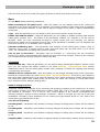
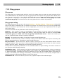
3.3 ASL virtual port
ASL virtual port is used for connecting plain analog phone or fax. This virtual port enables detection
of DTMF and pulse dialling and also CLIP transmission using DTMF or FSK. Parametres are divided
into logical sections.
Stack status
This field displays information about stack and its actual state. In the case of ASL virtual port you can
see following states:
a) null
b) config
c) on_hook
d) off_hook
e) error_stop
f) error_start_req
27
ASL virtual port
3.3
Figure 1 View of hardware configuration for ASL virtual port.
Line parameters
Impedance – This parameter determines impedance of the hybrid according to preset models (User,
ETSI 600, Germany and Real 600).
Line model – This parameter determines another parameters of the hybrid according to preset
models EIA0 to EIA7 (e.g. EIA0 represents model of 100m long line).
Signalling type – Type of signalling of Active state. You can choose between Reverse polarity, Tarif
pulse or Simple.
Tariff pulse type – It defines source for tariff pulse sending. You can choose between 12 kHz, 16
kHz or none.
Incoming parameters (dialing from phone)
Call type – Parameter determines prefered type of communication on this carrier. You can choose
between Voice, FAX, A3,1kHz Audio and 56kb Modem.
DTMF dialling enabled – When it is checked, carrier is able to detect DTMF dialing from analog
phone.
Pulse dialling enabled – When it is checked, carrier is able to detect pulse dialing from analog
phone.
FLASH length [ms] – Parameter sets the maximum time of the FLASH transmitted from the local
phone to the PbX. Default duration is set to 150 ms. Minimum of this parameter is on 80 ms.
Disable port DTMF detection – With this parameter you can enable DTMF detection using detector
on the board. Otherwise is detection executed by internal detectors. Number of detectors is limited
and this way you can save them for ports without this possibility.
Outgoing parameters (phone rings)
CLI broadcasting mode – Parameter defines prefered method of CLI presentation (Calling Party
Number) transmission. You can choose between DTMF, FSK or none.
28
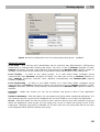
CO virtual port
3.4
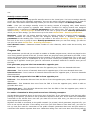
3.4 CO virtual port
This is the analog carrier for connection of state analog line (central exchange). This carrier dispose
only with DTMF transmitter and that is why you have to route incoming call directly to final
destination or into DISA object. With DISA you are able to detect DTMF symbols and route the call to
specific destination. Parametres are divided into logical sections.
Stack status
This field displays information about stack and its actual state. In the case of CO virtual port you can
see following states:
a) null
b) config
c) on_hook
d) off_hook
e) error_stop
f) error_start_req
Figure 1 View of hardware configuration for CO virtual port.
Line parameters
Impedance – This parameter determines impedance of the hybrid according to preset models (User,
ETSI 600, Germany and Real 600).
Line model – This parameter determines another parameters of the hybrid according to preset
models EIA0 to EIA7 (e.g. EIA0 represents model of 100m long line).
Signalling type – Type of signalling of Active state. You can choose between Reverse polarity, Tarif
pulse or Simple.
29
GSM virtual port
3.5
Tariff pulse type – It defines source for tariff pulse sending. You can choose between 12 kHz, 16
kHz or none.
Outbound way parameters (from PbX)
Current detection timeout [ms] – Time for detection of the current on the picked-up carrier. If no
current is detected in this time, a failure is reported.
Dial tone wait timeout [ms] – This parameter specifies the time of waiting prior to dialing the
numbers to the carrier. The presence of dial tone will be tested during this time after checking the
"Check dial tone" option.
Dial to connect timeout [ms] – Maximum time for waiting with dialing to an external line, the time
monitoring is renewed after each digit entered. If the entry of a digit is not detected within this time,
a connection will be attempted.
Check dial tone – This checkbox enables dial tone testing on this carrier. It will be tested for time
set in parameter Dial tone wait timeout.
DTMF dialling enabled – When it is checked, carrier is able to detect DTMF dialing from analog
phone.
Pulse dialling enabled – When it is checked, carrier is able to detect pulse dialing from analog
phone.
FLASH length [ms] – Parameter sets the maximum time of the FLASH transmitted from the local
phone to the PbX. Default duration is set to 150 ms. Minimum of this parameter is on 80 ms.
Don't use port DTMF detection – With this parameter you can enable DTMF detection using
detector on the board. Otherwise is detection executed by internal detectors. Number of detectors is
limited and this way you can save them for ports without this possibility.
Inbound way parameters (to PbX)
Ring pulse timeout [ms] – This parameter sets up minimal time of ring current needed for ring
detection. If the time of ring current is shorter than preset time, ring will be ignored.
Ring pulse treshold [V] – This parameter sets up minimal ring voltage needed for ring detection. If
the ring voltage isn't higher than preset value, ring will be ignored.
Ring pattern timeout [ms] – Parameter sets minimum length of the period for alerting detection.
CLI reception mode – Parameter defines prefered method of CLI presentation (Calling Party
Number) reception. You can choose between DTMF, FSK or none.
CLI reception timeout [ms] – Parameter sets timeout for CLI detection. It is counted from the end
of the first ring. This option is activ only if DTMF or FSK reception mode was selected.
Polarity wait timeout [ms] – Parameter sets timeout for waiting for the reverse polarity. This
option is activ only if reverse polarity is used on this virtual port.
Call rejection timeout [ms] – If PbX needs to reject call incoming call on CO port, it has to pick up
and hang up. With this parameter you can define duration of this action. If this duration is too short,
adverse party can't recognize it.
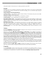
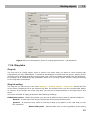
3.5 GSM virtual port
In the menu Virtual ports – GSM are listed all GSM virtual ports of the PbX. Parametres are divided
into logical sections.
30
GSM virtual port
3.5
Stack status
This field displays information about stack and its actual state.
Network selection
Roaming enabled – With this option you can enable roaming for concrete GSM virtual port.
Manual network selection – If this option isn't checked, inserted SIM tries to log into the prefered
network automatically. If it is checked, you have to enter correct network code and inserted SIM
card tries to log only into this concrete network. If this network is unreachable, SIM card doesn't try
to log into another network.
Network code – If needed, you have to fill in international network code composed from 5 digits
(e.g. T-mobile CZ= 23001, O2 CZ=23002, Vodafone CZ=23003).
Network name – This parameter shows name of the network corresponding with network code
entered within parameter Network code.
Signal diagnostic
Signal measuring – select this option to enable signal level measuring for a selected carrier.
Signal monitoring – here enable signal level monitoring for a selected carrier. If the signal level
drops below the value specified in the Poor signal level parameter, a red exclamation mark appears
on the port in the Hardware – Boards menu and a red text is displayed in the upper stack status
field. This poor signal status gets changed after the signal level exceeds the value specified in the
Good signal level parameter. The interval between the values represents hysteresis.
31
GSM virtual port
3.5
Figure 1 View of hardware configuration for GSM virtual port.
GSM interface parameters
Hide number – This checkbox enables calling with suppressed calling party number (CLIR – Calling
Line Identification Restriction). This function must be supported by the network (by the operator).
Otherwise calls with suppressed identification are refused with corresponding cause.
Relax timeout between calls – This parameter determines the idle period between two calls. It
concerns only calls going out from the PbX through GSM carrier, not the incoming calls. During this
time are all outgoing calls refused with the cause 34 – no circuit/channel available.
DID transmission in number – With this parameter you can enable special function of transmission
number for direct dialling within called number. This function is supported only in some networks.
DID separator – With this character is separated called number of the SIM card and DID number
(number for direct dialling).
Diasable port DTMF detection – With this parameter you can enable DTMF detection using detector
on the board. Otherwise is detection executed by internal detectors. Number of detectors is limited
and this way you can save them for ports without this possibility.
GSM modul diagnostic
Producer – Information about board manufacturer.
Type – Information about type of the board.
Firmware revision – This field shows software revision of firmware which is uploaded into the
board.
32
SIP virtual ports
3.6
Module IMEI – This field shows detected IMEI number.
GSM network diagnostic
State – This field shows actual state of the port. According to this state you are able to detect some
problems with logging into the network. For example the state PIN REQUESTED means, that SIM card
needs PIN code, which you have to insert or you can also disable PIN requesting at the SIM card.
Otherwise the SIM card can't be logged into the network.
Logged network – This field shows actual network code. It is international code of the network into
which is SIM card logged at the moment.
Network name – This field shows name of the network into which is SIM card logged at the
moment.
Signal – This parameter shows actual level of the signal (if it is activated). When the level of the
signal is low, it could be reason for logout from the network. Sometimes it can happen that SIM card
is logged, but you are not able to realize calls because of higher error rate.
SIM number – This field shows detected number of inserted SIM card.
PIN – To this field you have to enter the PIN code if it is required and it wasn't entered within the
menu SIM – SIM cards for this SIM card.
PUK – To this field you have to enter the PUK code if it is required and it wasn't entered within the
menu SIM – SIM cards for this SIM card.
SMS centre number – To this field you have to enter the SMS centre number if it is required and it
wasn't entered within the menu SIM – SIM cards for this SIM card.
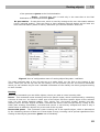
3.6 SIP virtual ports
3.6.1 SIP Gateway
SIP gateway virtual port is used for creating trunk between two PbXs or to connect your PbX to the
public network via one of the VoIP providers. All parameters are divided into logical sections.
Stack status
This field displays information about stack and its actual state.
Basic parameters
Port – Here you have to fill in number of used UDP or TCP port (it depends on following setting) for
communication with opponent.
Transport layer – It defines transport layer of this interface. You can choose between TCP and
TCP&UDP. If you use both, higher priority has UDP, but for packets longer then 1300 bytes will be
used TCP protocol.
Realm – It defines own address used within header From.
Via header – It defines content of Via header. You can choose between following options:
IP address – Via header is filled with CPU IP address.
FQDM – Via header is filled with PbX hostname, which was entered on the IP interface of the PbX.
NAT – In this case is filled static IP address of NAT. NAT has to be configured corretly, else
signalization from opponent can't reach your PbX.
STUN – Here you can enter address and port of STUN server, used for discovering actual address
behind NAT.
Authorization required – With this option you can enable authorization for your opponent. For
authorization are used data from user logins.
33
SIP virtual ports
3.6
Figure 1 View of configuration menu for SIP gateway.
Connect to gateway
Host – It defines Realm of the other side of trunk connection (VoIP provider or another PbX).
Port – It defines port on the other side of trunk connection. To this port you have to send SIP
messages.
Register line – It enables line registration. If line isn't registered, no call establishments are done on
this virtual port. All attempts are rejected with corresponding cause within PbX.
Expiration – With this parameter you can define registration expiration. Final value can be defined
by opponent (if he needs shorter).
Authorisation data
Login – Parameter is used as name for connecting to the user which requires authorization.
Password – Parameter is used as password for connecting to the user which requires authorization.
RTP interface
Name – Shows only name of concrete RTP interface of the PbX.
UDP min – Here you have to set up lower limit for used UDP port range for RTP stream.
UDP max – Here you have to set up higher limit for used UDP port range for RTP stream.
NAT – With this parameter you can enable routing of RTP stream through NAT.
NAT source – In the case of using Fixed IP in the column NAT, you have to fill in concrete NAT IP
address to this column.
NAT base – In the case of using Fixed IP in the column NAT, you have to fill in concrete NAT port to
this column.
34
SIP virtual ports
3.6
Codecs
Supported – In this field you can find list of supported codecs. You can't find here codecs which were
selected as used.
Selected – In this field you can find list of codecs, which are used for communication on this virtual
port. Within context menu is another option for setting features of selected codec.
DTMF according to RFC2833 – With this option you can enable transmission of DTMF according to
RFC2833.
Fax T.38 – With this option you can enable fax transmission according to recommendation T.38. If
this option is checked, it is changed to link with advanced settings. Recommended setting is TCF –
Transfer, Error correction – Redundancy and No compression.
Figure 2 View of configuration part for setting codecs.
3.6.2 SIP Proxy
SIP proxy virtual port is used for connecting SIP terminals to the PbX. All parameters are divided into
logical sections.
Stack status
This field displays information about stack and its actual state.
Basic parameters
Port – Here you have to fill in number of used UDP or TCP port (it depends on following setting) for
communication with opponent.
Transport layer – It defines transport layer of this interface. You can choose between TCP and
TCP&UDP. If you use both, higher priority has UDP, but for packets longer then 1300 bytes will be
used TCP protocol.
Realm – It defines own address used within header From.
Via header – It defines content of Via header. You can choose between following options:
IP address – Via header is filled with CPU IP address.
FQDM – Via header is filled with PbX hostname, which was entered on the IP interface of the PbX.
NAT – In this case is filled static IP address of NAT. NAT has to be configured correctly, else
signalization from opponent can't reach your PbX.
STUN – Here you can enter address and port of STUN server, used for discovering actual address
behind NAT.
Authorization required – With this option you can enable authorization for all terminals. For
authorization are used logins and passwords from user logins, according to stations which are
35
SIP virtual ports
3.6
assigned to the specific terminal on the tab Stations.
Figure 3 View of configuration part related only to SIP proxy.
Proxy parameters
Registrations validity – With this parameter you can define time of validity for terminal
registrations. After expiration each terminal has to send new register request. Parameter could be set
in range 30 – 3600s.
Terminals
This section is used for terminals management. If terminals aren't created then VoIP phones can't
register to this SIP proxy. Registered phone is indicated by new connection at concrete terminal. To
one terminal you can register more than one phone. In the case of outgoing call to such terminal are
alerted all its registered phones until first of them accepts call. Incoming calls are identified according
to stations which are assigned to terminals on the tab Stations.
RTP interface
Name – Shows only name of concrete RTP interface of the PbX.
UDP min – Here you have to set up lower limit for used UDP port range for RTP stream.
UDP max – Here you have to set up higher limit for used UDP port range for RTP stream.
NAT – With this parameter you can enable routing of RTP stream through NAT.
NAT source – In the case of using Fixed IP in the column NAT, you have to fill in concrete NAT IP
address to this column.
NAT base – In the case of using Fixed IP in the column NAT, you have to fill in concrete NAT port to
this column.
Codecs
Supported – In this field you can find list of supported codecs. You can't find here codecs which were
selected as used.
Selected – In this field you can find list of codecs, which are used for communication on this virtual
36
SIP virtual ports
3.6
port. Within context menu is another option for setting features of selected codec.
DTMF according to RFC2833 – With this option you can enable transmission of DTMF according to
RFC2833.
Fax T.38 – With this option you can enable fax transmission according to recommendation T.38. If
this option is checked, it is changed to link with advanced settings. Recommended setting is TCF –
Transfer, Error correction – Redundancy and No compression.
3.6.3 Advance settings
SIP
Always mediate RTP – If this option is checked, all calls are connected through the VoIP board. PbX
serves as RTP proxy. If this option isn't checked, VoIP calls are connected directly terminal to
terminal (only RTP streams) and they don't charge the PbX.
Reverse RTP negotiation – With this option you can define way of codecs negotiation. If this option
isn't checked, codecs are offered already in the message Invite.
Use short headers – It enables using of short headers (e.g. From = f, To = t, Via = v).
Dedicated Registrar – It is used only on gateway and it enables to transfer registrations to another
destination.
Address – Address of selected Registrar server.
Port – Port of selected Registrar server.
Aliases
This section enables to define addresses which will be also accepted. It is used for PbXs situated
behind NAT. Address of the packet and address in it can be different.
RTP
TOS – This section defines outgoing parameters for all packets. This setting is then used by network
elements.
Figure 4 View of dialogue box for managing advance parameters of VoIP.
37
Virtual port options
3.7
DSP – This section can be used for transferred data optimalisation. When it is enabled packets aren't
sent needlessly if user doesn't speek. Shortcut VAD means Voice Activity Detector.
Generate comfort-noise – With this parameter you can enable generating of some noise to the
background of the call.
Mask lost packets – With this option you can activate optimalisation for lost packets masking. It can
be used only by lower error rate, because it is based on some presumption.
RTCP
Send with period [s] – With this parameter you can set period of sending information about call
(establishment, disconnection, ...).
Echo suppression
With parameters of this section you are able to suppress echo.
Jitter buffer
With parameters of this section you are able to suppress jitter.
3.7 Virtual port options
Introduction
Menu Virtual ports you can use for setting up of virtual port types and virtual ports. In the menu
Virtual ports - All you can see all virtual ports independently of their type. For easier orientation are
virtual ports divided according virtual port types and they are also coloured according to stack type. If
you want to display only specific type of virtual ports, you can use other submenus in the menu
Virtual ports. At the beginning are colours of virtual ports following:DSS1 BRI, DSS1 PRI,
CORNET, ASL, CO, GSM, SIP Proxy, SIP Gateway, AUX. This setting can be changed within
application setting, as is described in the chapter 1.2 About application.
Creating virtual ports
At the beginning inhalts database two basic types of virtual ports – Default IN and Default OUT.
Virtual ports are created automatically in the menu Hardware - Boards. Another virtual port and
virtual port types can be created manually by following options of context menu:
Add virtual port type – With this option you can created new virtual port type. If you want to
assign virtual ports to created virtual port type, you can use function Drag&Drop or parameter Type
on the tab Basic.
Add virtual port – With this option you can initiate dialog box for adding new virtual port. within this
dialog box you have to enter name and choose stack type. Stack type is chosen from list, which
depends on submenu where was option used. If it was in the menu Virtual ports - All, are in list all
stack types, but if you use this option for example in the menu Virtual ports - Cornet, in the list is
only this stack type. Manually created virtual ports aren't assigned to the physic ports. It has to be
done manually in the menu Hardware - Boards.
Delete – With this option you can delete selected virtual port or virtual port type.
Rename – With this option you can rename selected virtual port or virtual port type.
Following part brings description of the tabs which are used at virtual ports. All tabs and parameters
which are in following chapters defined are common for all virtual port types. Some parameters or
38
Virtual port options
3.7
tabs are used only at few virtual port types, because on others they haven't any sense.
Basic
The tab Basic brings following parameters:
Name according to the physic port – With this option you can change name of the virtual port
according to the physic port where it is assigned. This name consists of stack name and of hardware
address in the square brackets. In the case of manual change of this name is option automatically
unchecked.
Type – With this parameter you can assign virtual port to the specific virtual port type.
Enable call without station – With this parameter you can enable or disable incoming calls without
calling party number (CLI) . As default is this parameter enabled. For example it can be used in
situation, when you have connected terminal to certain physic port and currently you haven't
assigned any station to corresponding virtual port. If this parameter is enabled, you can establish call
from such terminal, if it is disabled, call is rejected.
Internal numbering plan – This parameter sets subtype of the calling party number (CLI) to
"Internal". Value "Yes" is usually used by inner ports and value "No" by outer ports. If it is set to
"YES", no normalization of calling party number is done.
Call on port is accounted – Parameter sets the indicator (a - accounted) into the accounting
sentence. It means, that outgoing calls through this port have to be charged. Thanks to the indicator
are corresponding accounting sentences easily seek able.
CLI section
Identification tab – With this parameter you are able to assign identification table to specific virtual
port. You can choose from tables created in the menu Routing - Identification tabs. Chosen
identification tab is used for calling party number (CLI) changing. It relates for outgoing calls through
corresponding virtual port.
Added prefix for external CLI – With this option you can assign selected prefix to the virtual port.
Prefixes are defined within the menu Global data - Global parameters. This prefix is then added to
the calling party identification for all external subtypes, but it doesn't influence number assignment to
the name from phone book. Added prefix can be used for easier call routing on virtual ports which
don't support number subtype (analog, SIP).
Number subtype section
Parameter defines final subtype of the incoming and outgoing numbers at this virtual port. It covers
calling party number (CLI) and called party number (CPN) also. If it is set to "No", final subtype of
the number is "Unknown". If it is set to "Yes", finale subtype of the number corresponds with
incoming subtype, except incoming subtype "Unknown", which is changed by rules set in the part
localization. Generally is this parameter on the virtual port type Default IN set to "Yes" and on the
virtual port type Default OUT to "No".
You can set following:
Incoming CLIP – Parameter sets whether incoming subtype of calling party number will be retained
or not.
Incoming CPN – Parameter sets whether incoming subtype of called party number will be retained
or not.
Outgoing CLIP – Parameter sets whether outgoing subtype of calling party number will be retained
or not.
Outgoing CPN – Parameter sets whether outgoing subtype of called party number will be retained or
39
Virtual port options
3.7
not.
Autoclip routers section
This part is used for assigning specific autoclip router to the virtual port. You have to assign autoclip
router for calls and for messages separately, but you can assign the same autoclip router to both of
them. More information about autoclip routers you can find in the chapter 7.4 Autoclip routers.
Calls – Here you can assign autoclip router for saving records of outgoing calls, which weren't
accepted or were rejected by opposite user. Another condition for saving records into assigned
autoclip router is assigning of autoclip parameters to the calling user. This you can realize in the
menu Routing - Users & groups on the level of the user or group of users. Autoclip parameters
which you can then assign, you have to set up in the menu Global data - Autoclip parameters.
Messages – Here you can assign autoclip router for saving records of outgoing SMS messages.
Another condition for saving records into assigned autoclip router is assigning of autoclip
parameters to the sending user. This you can realize in the menu Routing - Users & groups on
the level of the user or group of users. Autoclip parameters which you can then assign, you have to
set up in the menu Global data - Autoclip parameters.
Own channel count – Parameter shows number of voice channels, which could be served by this
virtual port.
Progress info
With parameters on this tab you are able to enable or disable progess tones, which are played to the
user during specific period of the call. In some cases are progress tones generated by the PbX, in the
others are progress tones transmitted from the network. Final effect isn't dependent only on set up of
users virtual port, but it is combination of set up of users virtual port (mostly inner port of the PbX)
and set up of opposite virtual port (port for connection to another networks or another inner port of
the PbX).
Port generates progress info from network to opposite port:
Dial tone – Port is source of network dial tone for opposite port, if this one demands dial tone.
Alert tone – Port is source of network alert tone for opposite port, if this one demands alert tone.
Disconnect tone – Port is source of network disconnect tone for opposite port, if this one demands
disconnect tone.
Port requests progress info from PBX or from opposite port:
Dial tone – Port demands dial tone from the PbX or from the opposite port, which is able to generate
dial tone.
Alert tone – Port demands alert tone from the PbX or from the opposite port, which is able to
generate alert tone.
Disconnect tone – Port demands disconnect tone from the PbX or from the opposite port, which is
able to generate disconnect tone.
For easier orientation in this questions are here following examples:
1) User A has connected phone to the inner port of the PbX. If you want him to hear dial tone after
picking up the phone, you have to set up dial tone request for this port. If the same user establishes
connection to the second inner user and you want him to hear alert tone, you have to set up alert
tone request at the same port.
2) When the PbX is connected to the public network (or private) which generates progress info, you
have to set up this tab also. If the calling user from your PbX wants to hear alert tone, you have to
set up, that port used for connection to the public network generates alert tone and port where is
connected user station requests alert tone. Otherwise calling user can't hear alert tone during calls to
40
Virtual port options
3.7
that public network. Disconnect tone is mostly generated by own PbX.
Overlap
Overlap is one of two methods of called party number (CPN) sending. In the case of overlap dialing
isn't called party number transmitted all in the SETUP message, but it is transmitted digit by digit in
the INFO message.
Setup consists of following parameters:
Overlap sending – This parameter enables overlap sending in the direction from port into the PbX.
Above all it is used at ISDN virtual ports.
Overlap receiving – It isn't implemented yet. Parameter is inactive.
Overlap dialling – It isn't implemented yet. Parameter is inactive.
First digit timeout [ms] – This parameter sets timeout for first digit dialling. It starts at the
moment of pick up of the microtelephone. After timeout expiration isn't user able to dial another
digits, he obtains the disconnect tone and the call establishment is ended. Default value for this
parameter is set to 14 s.
Next digit timeout [ms] – This parameter sets timeout for next digit dialling. Timeout is restarted
after each received digit. When it expires without receiving next digit, call establishment begins. It
depends on sequent routing procedures, if dialled number is sufficient. Default value for this
parameter is set to 6 s. If you want to begin call establishment before timeout expiration, you can
press button #.
Stations
On the tab Stations is shown list of stations assigned to this virtual port. This tab you can find in
three forms depending on virtual port type:
a) On the virtual ports BRI, PRI, SIP Gateway and SIP Proxy is form adapted to necessity of
terminal using. Terminals are created on the tab HW. They are used for authorization, MSN numbers
and you can also assign stations to them. Tab Stations consists of three parts. First on the left side
is window with list of created terminals. If you haven't created any terminal, you can use Default one.
In the middle is situated window with list of the stations assigned to selected terminal. On the right
side of the menu is situated field, where you can specify active station. This is important if you have
assigned more stations to single terminal. To all stations you can realize call, but all outgoing calls
from this terminal will be identified as the active station and all calls will be accounted to this active
station too (except situation when you use service "Private call from my station").
b) On the virtual port Cornet is situation similar, but there aren't any terminals, because to this type
of virtual port you can connect only single terminal. Stations have possibility to be marked as Master
or Slave. If you have more stations on this virtual port, you can also specify active station (one for
type Master and one for type Slave).
c) On the virtual ports AVL, ASL and GSM is situation the simplest. Tab has there only two parts.
First one is used for stations assignment and the second for active station specification.
Properties
The tab Properties consists of many tabs, which are described in the separate chapter. This tab is
exceptional, because almost for all its parameters you can use hierarchical structure. This structure
and description of all parameters is situated in the chapter 9.1 Setting up the properties tab.
41
Virtual port options
3.7
Stack
The tab Stack is described in the chapter 3 Virtual ports, because it depends on stack type.
Messages
The tab Messages is used only on the virtual port types, GSM and SIP virtual ports, because on the
others it has no sense. This tab consists of following parameters:
Repeat at fail – With this parameter you can enable or disable repeated attempts for transmitting
received SMS messages.
Destination:
Type – This parameter sets type of the routing object, where are received SMS message transmitted.
Id – It sets specific object of above selected type.
Default user – Here you can set specific user, who will receive all incoming SMS messages, which
can not be routed to destination specified in the field Destination.
42
SIM cards
4.1
4 SIM cards
4.1 SIM cards
In the menu Carriers – GSM – SIM you can find list of all SIM cards of the PbX. After first inserting
of the SIM card into the port is automatically created new record in the database and parameters
which you fill (e.g. PIN), are used automatically by future detection of this SIM card. This menu
includes following parameters:
SimNum – This parameter shows detected identification number of the SIM card. This number is in
NsAdmin automatically used for SIM cards identification in the list on the left side of the menu.
Phone Number – This field has only informative character. You can fill the phone number of this SIM
card for easier orientation. This parameter has no function.
PIN – Personal Identification Number – In this field you have to insert PIN of this SIM card if
requested. This number is shared by the user and authentication system. If the SIM card PIN
requests and it is not filled or it is filled wrong, SIM card can't be logged into the network.
PUK – Personal Unblocking Key – In this field you can fill in PUK if you want or need. It is number,
which is used for unblocking the SIM card in the case, that it is blocked due to usage of wrong PIN
code.
SMS centre – This parameter you have to fill if you want to send SMS messages. In GMS network
isn't SMS routed directly to the final destination, but through SMS centre of the specific operator. It is
useful in the cases, when SMS messages can't be delivered immediately (e.g. target phone is
unavailable). SMS centre tries to deliver this message cyclical for preset time of validity. This
parameter is mostly automatically detected on the SIM card (preset from operator). Otherwise you
have to fill it manually.
Name – This field has only informative character. It can be used for separation of more SIM cards.
Port – This field has only informative character. It shows physic port, where is specific SIM card
detected at the moment.
43
Network interface
5.1
5 Network
5.1 Network interface
In the menu Network – Network interface you can manage all network interfaces, which are
present in the PbX. In addition to CPU interface are there ethernet interfaces of Surf boards. Bit rare
of all interfaces is 100 Mbit/s. This interfaces are used for communication with PbX, SMTP clients and
for signalling and RTP streams of VoIP calls. After opening menu Network – Network interface is
on the left side displayed list of ethernet interfaces of the PbX. On the right side of the menu you can
set up selected interface. In the case of ethernet interface of CPU are options following:
Get IP address from DHCP server – With this option you can enable getting IP settings from DHCP
server automatically. In this case are following sections inactive.
Use the following IP address – With this option you can enable following sections for setting of
static IP address and DNS servers.
IP address – It defines static IP address for this interface.
Subnet mask – It defines bit mask of the subnet.
Default gateway – It defines IP address of the router or PC through which PbX communicates with
outside of LAN.
Addresses of DNS servers
Prefered server – It defines IP address of primary DNS server.
Spare server – It defines IP address of secondary DNS server.
Host name – It defines host name of the PbX.
Domain name – It defines domain name of the PbX.
Description – This field has only informative character.
Producer – This field has only informative character.
5.2 Services Setting
5.2.1 Electronic mail (SMTP)
SMTP
Simple Mail Transfer Protocol (SMTP) is the internet protocol used for e-mail transmissions across
the Internet between clients and server. Protocol provides delivery via direct connection between
sender and receiver.
SMTP clients
The PbX NETSTAR can dispose of more than one ethernet interface. For communication with SMTP
server is always used ethernet interface of the CPU board. In the menu Global data – SMTP clients
you can create SMTP clients, which can later connect to SMTP servers and send e-mails. For correct
function of the service Voicemail you have to set up not only SMTP server, but also users e-mail
addresses.
44
Services Setting
5.2
Figure 1 View of configuration of SMTP clients.
Mail account – It shows only name of selected SMTP client. It can't be directly modified.
Network interface – Here you can choose network interface used for SMTP communication with
server. In this version you can choose for this purpose only network interface of CPU board.
Outgoing mail server – Here you have to enter IP address of SMTP server. If you use DNS server
you can use also domain name of your SMTP server.
Port – Number of port used for communication with SMTP server. Usually is used port 25.
Client address – This address will be used for identification of incoming messages within SMTP
server. Without correct setup of this parameter will probably SMTP server rejects all requests for
connection establishment!
Authentication – This parameter is used for choosing type of authentication for access to your email account on specified SMTP server.
Account name – Name of e-mail account registered by selected SMTP server. It is required by all
methods.
Password – Password for access to your account is required by all methods.
5.2.2 Time synchronization (NTP)
Within this menu you can define NTP server which will be used by PbX for time synchronization. After
checking option in upper part of menu you are able to enter IP address or domain name of concrete
NTP server. After saving data, PbX will try to synchronize time with preset NTP server. Result of this
action is always shown in the field Synchronization result. You can also see information about time
of another synchronization attempt.
45
Services Setting
5.2
Figure 1 View of menu for time synchronization.
5.2.3 Remote control (SNMP)
What is it SNMP?
The Simple Network Management Protocol (SNMP) forms part of the internet protocol suite as
defined by the Internet Engineering Task Force (IETF). SNMP is used in network management
systems to monitor network-attached devices for conditions that warrant administrative attention. It
consists of a set of standards for network management, including an Application Layer protocol, a
database schema, and a set of data objects. SNMP exists in three versions. Second version includes
in addition authentication and third version includes encryption. Most of current devices apply to
SNMP version two.
In communication by SNMP we have to differentiate between two sides – monitoring and monitored.
These parts can run on separate physic equipments or within one equipment. Monitored side is often
called as Agent and monitoring side is called Manager. On the monitoring side are collected
information about system state. Manager sends requests to Agent – mostly he requests some
information about system state. Agent provides reactions to requests from Manager.
Communication between Agent and Manager is often marked as SNMP operation.
OID alias Object Identifier is identificator, which is used for explicit identification of each value in
the SNMP communication. OID is created by numbers divided with points, where each point
represents one level of hierarchical structure of OID tree. Number identifications within separate
subtrees aren't unique and that's why is OID always sent as whole string. Each company and each its
product using SNMP management has its own international OID. MIB alias Management
Information Base is used for translation of OID strings into text, which can be more
understandable. MIB database can be completed by adding another MIB files.
Users
SNMP v3 is user oriented. User created within this part of configuration corresponds with USM (User
Security Model) in SNMP v3 and with community of other versions.
Authentication – Within this section you can define password and way of encryption for
authentication.
Protocol – For securing your password you can use methods MD5 or SHA.
Password – Here you have to enter password.
Privacy – Within this section you can define password and way of encryption for data transmission.
Protocol – For transmission securing you can use methods DES or AES.
46
Services Setting
5.2
Password – Here you have to enter password for encryption.
Access – Within this parameter you have to set rights of this user. You can do it by choosing from
the list of created rights.
Rights
Add default rights – With this option of context menu you are able to create default rights Internet
and Restricted. With these rights are created also filters on the tab Filters.
Title – It defines name of created right. This title is displayed by rights choosing on the tab Users.
Context – With text string can be identified concrete SNMP module within client address. This
parameter doesn't need to be filled.
Full match context – With this option you can enable requirement of full match including context.
Mostly it doesn't need to be used.
Security model – Within this parameter you can choose concrete security model (SNMP v1, SNMP
v2c, USM = v3) or option Every. In the case of using concrete method, it has to be used by
opponent, otherwise communication fails.
Minimal security level – Parameter offers three different models:
Authentication and privacy
Without authentication and privacy
Authentication only
Read filter – With this parameter you can set filter for reading by choosing from list of filters created
on the tab Filters. With it you can restrict access to PbX information for user with these rights.
Write filter – With this parameter you can set filter for writing by choosing from list of filters created
on the tab Filters. With it you can restrict writing within PbX for user with these rights.
Notify filter – With this parameter you can set filter for notifications by choosing from list of filters
created on the tab Filters. With it you can restrict notifications from the PbX to user with these
rights.
Figure 1 View of the menu for rights settings for SNMP users.
Filters
Derive – With this option you are able to create filter with same settings as has selected one.
OID root – Parameter sets root of OID tree, which is used as base for filter setting. OID structure
you can view as tree or as alphabetical list.
Exception – Parameter can change meaning of concrete rule. If this option isn't checked, defined
OID subtree is used. If this option is checked, using of subtree from this row is denied. Thanks to this
parameter you can create filter where is specified, that you use whole section 2.1 except its specific
section 2.1.3.
OID subtree – Within root you are able to choose specific sections, which can be used. Empty row is
used to enable whole above specified OID root. Each filter has to have minimally one rule. If you
don't need to use any specific rule within OID root, please use empty row. This is done, because filter
doesn't compare rules with OID root, but only with subtrees. If some defined rules are subsets of
another, than is always used the most common rule (the shortest one).
47
Services Setting
5.2
MIB files
Add – With this option you can add MIB files used MIB database extension.
Delete – With this option you can delete selected MIB file.
Recompile – With this option you can recompile selected MIB file.
File – In this column is shown path to the source of MIB file. This path is important for using option
Recompile.
State – This column shows actual state of MIB file. You can see here states Compiled, Not
compiled and Not found. States of MIB files are also indicated by icons on the beginning of each
row as you can see on the figure 2.
Additional information – This column is used for displaying additional information.
Figure 2 View of the section for MIB files management.
Meaning of Notification filter options according to RFC3415
•
Internet access:
• subtree 1.3.6.1
•
Restricted access:
• System – subtree 1.3.6.1.2.1.1 according to RFC3918
• SNMP – subtree 1.3.6.1.2.1.11 according to RFC3918
• snmpEngine – subtree 1.3.6.1.6.3.10.2.1 according to RFC3411
• snmpMPDStats – subtree 1.3.6.1.6.3.11.2.1 according to RFC3412
• usmStats – subtree 1.3.6.1.6.3.15.1.1 according to RFC3414
When you choose filter Internet, after PbX restart you will receive following traps:
1) ColdStart (PbX announced that it was restarted or switched off)
2) Then is sent information about all ports in stave "L1 active". It means active ports Cornet, BRI and
PRI.
3) Another information is about all CO and ASL ports.
4) Then come information about logging of GSM ports with SIM cards.
5) After it are sent only information about error states and theirs elimination: DSS1 deactivation or
higher BER or SLIP (according to setting), Cornet deactivation (according to setting), ASL – error, CO
– error, GSM – logout or bad signal (according to setting).
Answer
In this tag specify the ports and the client from which the PBX is able to receive requests.
Peer port – On this port PbX expects SNMP requests and acknowledgements. Default port for SNMP
is 161.
From this client address only – With this option you can lock receiving from specific address.
48
Services Setting
5.2
Figure 3 View of the part for setting of listening port.
Notification
Client address – It defines IP address or domain name of client, where are sent notifications
according to the below specified filter.
Client port – It defines client port where are sent notifications.
Used local port – If you need you can also specified port of the PbX which is used for sending
notifications.
Notification type – Within this section you can select type of used notification. For SNMP v1 you can
choose only Traps. In other cases are available also inform requests.
Trap – SNMP message sent to the client in the case of some event, which has to be notified. This
message doesn't support any acknowledgement.
Inform request – SNMP message sent to the client in the case of some event, which has to be
notified. This messages have against traps advantage, that all send messages can be resent when
doesn't come any acknowledgement.
Repeat – It defines count of attempts for sending concrete notification.
In interval – It defines time interval in which is expected confirmation about notification reception
from the client.
Version – In this section you can specify way of notification coding according to used version of
SNMP.
SNMP v1
SNMP v2c
SNMP v3
49
Services Setting
5.2
Figure 4 View of the configuration menu on the tab Notification.
User/Community – Here you have to define concrete SNMP user, which corresponds to USM for
SNMP v3 and to community for other versions.
Filter – Here you have to define filter for notifications. Longer OID for root or subtrees means stricter
filter.
Security level – This parameter can be used only for SNMP v3 and it defines level of security for
notifications. You can choose between following:
Authentication and privacy
Without authentication and privacy
Authentication only
Context – With text string can be identified concrete SNMP module within client address. This
parameter doesn't need to be filled.
5.2.4 Message bridge
Menu Message bridge is used for management of ports, through which you are able to connect to
your PbX. Basically you can only add or remove port within this menu. For each port you can then
set if it requires authorization or not. After creating database is here only port 6992, which requires
authorization.
50
Services Setting
5.2
Figure 1 View of configuration in menu Message-bridge.
If you are connected to the PbX via port with authentication, basically you don't see tab Database,
which can be used for direct configuration. If you want to see it, you have to assign rights for reading
and writing for this user. It could be done within the menu Users – Users rights. Another possibility
is to connect to your PbX via port without authentication. In such a case you expose your PbX to
danger of unauthorized access. Access to database isn't necessary and it should be used only by
experienced technicians.
As you can see on figure 1, you are able to define other parameters for each port (except
authorization requirement).
HeartBeat packets – Enable or disable sending of keep alive packets on this port. Packets are used
for communication preserving.
HeartBeat interval – It defines time interval between keep alive packets.
5.2.5 System
Communication ports
From firmware version 2.3.0 are ports 22 (SSH) and 23 (TELNET) in the default configuration closed,
because of improvement of the system security. Whenever you want, you are able to open each port
via console or via this configuration tool. If you decide to open some of these ports, we strongly
advise to change your password! Command syntax for password changing is following:
passwd root <Enter> Changing password for root New password: <Enter> Retype password:
<Enter>
This password will be changed regardless of original password. If you forget this password, you can
change it in the same way whenever you want. The only thing you have to know is your login name
to console.
Menu System
If you need to open or close access to some of these servers via configuration tool, you have to go to
menu Network – Service setting – System. Using simple option Enabled or Disabled you can
open or close access to concrete server. Meaning of particular options is following:
Internal server of Assistant – This option is used when you want to open or close access to the
web server of Assistant (user web application).
Telnet server – This option is used when you want to open or close access to the system via Telnet
protocol.
SSH server – his option is used when you want to open or close access to the system via SSH
protocol.
51
Global parameters
6.1
6 Global data
6.1 Global parameters
Switch on regime ME
With this option you can switch your PbX to regime Mobility Extension, which is used in special cases
when is PbX connected as gateway between another PbX and different types of private or public
networks. When this regime is activ, all Flash patterns and DTMF characters are sent directly to the
specified port. PbX in this mode does't react to these patterns and DTMF characters. This function
has nothing to do with Mobility Extension used for external stations of PbX!
Unselected as missed
This option sets up way of missed calls displaying. It refers to cases when one incoming call is routed
to some group of stations or to one user with more stations and this call is accepted on one of these
stations. If this option isn't checked then missed calls aren't displayed. If this option is checked
missed calls are displayed at all stations except that one, which has accepted the call.
Generate phone books from users
With this option you can define way of creating automatically generated phone books which you can
find in the menu Users – Phone books – Group generated. It could be generated either from
stations or from users. If this option is checked then this phone book is filled with user names and its
internal numbers. If this option isn't checked then this phone book is filled with station names and its
numbers.
Figure 1 View of configuration menu of Global parameters.
Global prefixes
Global prefixes are used for analog and VoIP virtual ports for easier dialing from list of missed calls.
Prefix isn't added in cases when calling party number has subtype Internal. You have to assign
52
Localization
6.2
concrete prefix to virtual port via parameter
Added prefix for external CLIP, which you can find on the tab Basic. Meaning of columns from tab
is following:
Prefix name – It defines name of prefix, which is used in another menus within configuration tool.
Prefix – Here you have to define concrete prefix, which is then added to calling party identification.
Group of users – In this column you are able to define groups of users, which can use this concrete
prefix. If any group isn't selected then is prefix valid for all groups of the PbX.
Example
From the public network comes call from number 777123456. Call is routed through the PbX to the
user Karel Furst, which belongs to the group of users Skupina 1. His VoIP phone is registered to SIP
proxy, which has assigned prefix PRI GTS (figure 1) in parameter Added prefix for external CLIP.
If is number 777123456 in phone book to user's phone is sent name of calling user and also his
number with added prefix 51. Presented calling party number is now 51777123456. If user Karel
Furst wants to call back to this contact, he can dial it directly from list of missed calls (or received
calls). Call is correctly routed to the specified port with minimal costs (it depends on routing).
6.2 Localization
Destination selection
In this field you have to set up numbers and prefixes according to international numbering plan. This
setting subsequently facilitate normalization of incoming and outgoing numbers. It could be used for
easier routing:
Destination – Here you can choose your location (country) from the list. Country code and access
codes will be filled in automatically. This settings could be changed manually if needed.
Number – This number presents country code within international numbering plan. For example for
Czech Republic is it number 420 and for Slovakia is it number 421.
Prefixes – This prefix presents access codes for access to international telephone network. By
default it is 00 and + for GSM network.
Figure 1 Menu for setting up of basic localization parameters of PbX.
53
Licences
6.3
Local settings
With checkbox Local calls possible you can open part of this menu, where you can setup national
parameters similarly as in the part International:
Number – This number presents national access code (area code). For example in Slovakia has city
Bratislava area code 2.
Prefixes – This prefix presents access codes for access to national telephone network.
Normalize CLIP
Normalize CLIP – Checked option sets up automatic cut of incoming calling party number (CPN) to
the shortest known format according to set localization. If this option isn't checked, you have to route
incoming calls via CPN routers to requested destination. This setting in effect means that numbers
+421XXX, 00421XXX, 0XXX and XXX are identical (only for routing).
Settings presented in this chapter are particulary done within the Initial Wizard by first
login to the system in online mode with new database.
6.3 Licences
Licence files
This part consists of list of installed licence files and of their basic description. Licence files you can
here instal or uninstal. Field consists of some columns with following meaning:
File – This parameter shows absolute path to specific licence file within the system data space.
State – Parameter shows actual state of specific licence file within the system (e.g. Loaded, Not
loaded, Bad CPU, ...).
E1 ports – Parameter shows the number of licensed ports for ISDN PRI.
E1 channels – Parameter shows the number of licensed channels for ISDN PRI.
SIP terminals – Parameter shows the number of licensed terminals for VoIP telephons. Without
these terminals you aren't able to sign on your VoIP station to the SIP proxy.
ME – Parameter shows the number of licensed external stations (ME – Mobility Extension). If you
want to enable parameter Transfer on the tab Properties – ME at one of the hierarchical levels,
you will need more licences. When you set this parameter to "Yes" at the user, then you will need as
many licences as he has stations. When you set this parameter to "Yes" at the carrier type, it will be
even more complicated. You have to count stations, which are assigned to the carriers of this carier
type. This number applies to count of required licences for parameter Transfer.
Figure 1 Example of Netstar with three valid licences.
54
Language packages
6.4
Licences
This part displays transparent table with content of selected licence file. Field consists of some
columns with following meaning:
Licence type – It shows specific type of licensed service, interface or object within the system.
Subtype – This column defines specific licence within its type.
Owned – This column shows number of licensed channels, terminals or services.
Requested – This column is very important, because it shows currently requested number of
channels, terminals or services.
Remark – In this column you can see miscellaneous warnings (e.g. warning, that your licence is
insufficient or that it will expire soon).
If no licence is installed, the system is in the trial mode. After expiration of this trial licence (800
hours) is system blocked and you aren't able to use it until you install acceptable licence.
Figure 2 View of part of licence features table.
6.4 Language packages
Language package
List of installed language packages you can find in the menu Global data – Language packages.
This menu isn't only list of available packages, but you can install here another language packages if
you want. Language package consists of progress tones, messages for services and texts for menu of
digital terminals StarPoint. If you want to install new language package, you have to click on the right
button and in displayed context menu select the option Install language package. Then you can
choose path to the packed file. If you want to uninstall some language package, you have to select it,
click on the right button and select the option Uninstal language package. The table with installed
language packages consists of four columns.
55
Services
6.5
Figure 1 View of the menu where you can add language packages.
Meaning of each column is following:
Name – This column shows name of installed language package. Default packages are named
according to their language.
Storage – This column defines part of way to the package storage within the system data space.
Builtin means directory /opt/netstar and Internal means directory /data/netstar. Together with
column Directory gives absolute path to the storage.
Status – This column shows status of package installation.
Directory – This column shows way to the package storage within the system data space. Together
with column Storage gives absolute path to the storage.
6.5 Services
Services division
Services supported by PbX Netstar can be divided into three groups – User, Station and Others.
User – This group consists above all of user forwardings, including forwarding to the voicemail, then
of services as recording, playing and deleting of voicemail progresses, PIN changing, user's login to
the bundle and so on.
Station – This group consists above all of station forwardings, setting of station ringing in the case of
calling to the user, station login to bundle and carrier, private call, call back to the station and call
assumption from the station and so on.
Others – This group consists of all remaining services – progress tones recording, setting of date and
time, call back to the number, global setup, call assumption from the group, conference calls,
connection to call, profile activation and so on.
Services setting
In the menu Global data - Services is on the left side displayed list of the supported services.
Default list you can create by context menu and its option Default. On the right side of this menu
you can set up selected service. Within each service are displayed parameters, which you are able to
set up. Above all there are progress tones and messages for various period of service settings,
activation of the PIN for service usage, time of alerting and setting of the default destination for call
routing within services. If the service requests PIN, it is necessary to set PIN to the calling user,
otherwise is this service for him unavailable!
56
Services
6.5
If you want to use some service, you have to dial specific prefix, which is routed to the routing table
according to called number. Default router for services is situated in the menu Routing - Routers
and is called Services:
Figure 1 View of part of router Services, which is used for routing calls to services.
Another possibility how to activate or deactivate some service is activation via messages. This
method can be used only for group of services, which doesn't need call in active state for service
settings (e.g. all call forwardings, PIN changing, Profile activation, ...).
Description of some services
Some services need more than only progress tones or messages settings. In this menu you can find
explanation of some parameters that aren't common.
a) Private call
By this service you have to set up destination in the field Destination. You can choose between
possibilities "Nothing" (uses setting from calling user) and "Router" (you have to set specific router).
This destination is then used for call routing within this service.
b) Park
By this service you have to set up parameter Maximal time of parking. Default value is set to 180s.
Parked user hears Music on Hold. After expiration of set timeout is parking place relieved and call
begins to alert at that station, which parked it before. Parked user hears in this time alert tone.
57
Progress tones
6.6
6.6 Progress tones
Introduction
Progress tone is general name for all tones and announcements played within the PbX. After creating
new database has PbX set of default progress tones. Amount of progress tones and language
alternations depends on installed language packages. This basic set could be extended with own files,
tones or by connecting of external audio inputs (e.g. mp3 player). Whole menu is logicaly divided into
couple of tabs.
Figure 1 View of tabs in the menu Progress tones.
Progress list
The progress tone represents complete tone, which is used for playing to the user. Each progress has
to contain minimally one source.
Progress list
In this part of tab Progress list you can find all defined progresses of your PbX. You can also find
here progress tones created by the user. Via context menu from this part you can use following
functions:
Add – With this option you can add new progress.
Rename – With this option you can rename selected progress.
Delete – With this option you can delete selected progress.
Delete all – With this option you can delete all progresses.
Add default progresses – With this option you can complete default set of progresses if some of
them were deleted. Changes made within default progresses are preserved and progresses created
by user aren't changed or deleted.
Restore default progresses – With this option you can setup default set of progresses to their
basic form. Progresses created by user aren't changed or deleted.
Information about progress
Name – Parameter shows only name of selected progress and it can't be configured within this
section.
Number – Number of progress used within the services for recording, playing and deleting user's
progresses.
Allow sharing progress – With this parameter you can enable sharing of selected progress for more
listeners. This way you can spare internal players of the PbX. When this option is checked then
progress isn't played from the beginning, but from the actual position. That's why is this function
used mostly for Music on Hold and similar progresses.
Language – Selection of language for playing the progress.
Duration [s] – It shows length of progress.
Actualize – It is used for updating information about selected progress.
58
Progress tones
6.6
Play – It is used for playing selected progress.
Progress configuration
Action – In this column you can choose one of listed commands, which consequently defines
meaning of that row.
Repeat – It defines number of repeating. This command can be used only once within each progress
and it means that all rows from the beginning to this row will be repeated. Number of repeating is set
within the column Repeating.
Pause – This command is used for creating delays between tones and announcements. Timeout for
this delay is set within the column Duration [ms]. This command can't be used as first command. It
has to be used first after using row with command Play or Play progress.
Play – This command plays selected element for time set in the column Duration [ms]. If you set
value 0, element is played to its end.
Play progress – This command is used for playing another progresses. Played progress is specified
in the column Progress. Other columns aren't used.
Priority – For each row with command Play you can define more sources. If one of sources isn't
presently available, it can be replaced by another source. Priority of choosing these sources is made
within this column.
Progress – It defines concrete progress for playing within the command Play progress.
Own file – It defines concrete file for playing within the command Play. You can choose from files
defined within the tab Own files.
Tone – It defines concrete tone for playing within the command Play. You can choose from tones
defined within the tab Tones.
Input (AUX in) – It defines concrete audio input for playing within the command Play. You can
choose from audio inputs defined within the tab Audio inputs.
Repeating – It defines count of repeating for command Repeat. If this column is set to value 0,
progress is played always. If it is set to 1, whole section from the beginning is played just ones.
Duration – This column defines duration for commands Play or Pause.
Language pack files
Language pack files list
This section shows all files of installed language packages, which you can use as sources for
progresses. Via context menu of this section you can save these files to local disk if you need.
Related progress list
In this section of screen are listed all progresses which are using upwards selected file. You are able
to use there all functions from context menu as on the tab Progress list.
Other sections
Sections Information about progress and Progress configuration are common for all tabs and
meaning of theirs parameters is described in part Progress list.
59
Progress tones
6.6
Own files
Own files
This section shows all files uploaded by user to the PbX, which can be used as sources for progress.
Context menu of this section has following functions:
Add – Is used for adding record. This record is then used as source for progress. After creating it has
no file. It has to be uploaded via section Own files source.
Rename – With this function you can rename selected record.
Delete – With this function you can delete selected record.
Delete record but keep file – With this function you can delete selected record, but keep its
uploaded file in the PbX.
Backup file to local disk – With this function you can download file of selected record to your local
disk.
Own files sources
Within this section you can upload own file and assign it to the created record in section Own files list.
Context menu of this section has following functions:
Add – With this option you can upload file with announcement for selected record.
Add record for existing file – With this option you can create record for existing file.
Delete – With this option you can delete file of selected record.
Delete record but keep file – With this function you can delete selected record, but keep its
uploaded file in the PbX.
Related progress list
In this section of screen are listed all progresses which are using upwards selected own file. You are
able to use there all functions from context menu as on the tab Progress list.
Other sections
Sections Information about progress and Progress configuration are common for all tabs and
meaning of theirs parameters is described in part Progress list.
Tones
Tones
This section displays all tones of the PbX, which can be used as sources for progresses. Context menu
of this section has following functions:
Add – With this function you can add new tone.
Rename – With this function you can rename selected tone.
Delete – With this function you can delete selected tone.
Delete all – With this function you can delete all tones.
Derive – This option is used for creating copy of selected tone.
Add default tones – With this option you are able to complete list of default tones in the case that
60
Progress tones
6.6
some of them were deleted. Made changes of other tones are preserved.
Restore default tones – With this option you are able to complete list of default tones. All changes
made within default tones are lost.
Tone configuration
In this section you can configure selected tone via table with three columns with following meaning.
Language – This column defines language for each row. You are able to create different forms of
tone for different languages. Action – Within this column you can use one of following actions for
each row.
425Hz – It plays tone with frequency of 425Hz. Duration of this tone is set in column Duration
[ms]/Repeating.
Repeat – With this option you can repeat rows from the beginning to this row. Count of repeating is
set in the column Duration [ms]/Repeating. If this column is set to value 0, section is played
always. If it is set to 1, whole section from the beginning is played just ones.
Silent – With this option you can define delays between rows with function 425Hz. If this action is
used on the first row, it has no function.
Duration [ms]/Repeating – In this column you have to enter duration for functions 425Hz, Silent
and Through or number of repeating for function Repeat.
Through – It has same function as action Silent, but in this case you are able to hear sounds of line
(if any).
Related progress list
In this section of screen are listed all progresses which are using upwards selected tone. You are able
to use there all functions from context menu as on the tab Progress list.
Other sections
Sections Information about progress and Progress configuration are common for all tabs and
meaning of theirs parameters is described in part Progress list.
Audio inputs
Audio inputs
This section displays all audio inputs of the PbX, which can be used as sources for progresses.
Context menu of this section has following functions:
Add – With this function you can add new audio input. Rename – With this function you can rename
selected audio input. Delete – With this function you can delete selected audio input.
Audio inputs sources
In this section you can assign concrete virtual port of Audio/IO/Relay board to selected Audio input.
For each port you have to define language for which is input used.
Related progress list
In this section of screen are listed all progresses which are using upwards selected audio input. You
are able to use there all functions from context menu as on the tab Progress list.
61
Ring tones
6.7
Other sections
Sections Information about progress and Progress configuration are common for all tabs and
meaning of theirs parameters is described in part Progress list.
6.7 Ring tones
Ring tones you can set up in the menu Tones & Rings - Ring patterns. Each ring tone consists of
ring pattern and cornet melody. Some terminals aren't able to change ring melody and use only ring
pattern. On the left side of the menu is displayed list of the created ring patterns. Via the context
menu you can add new ring patterns or remove them. During creation of the new database is this
menu filled with default progress patterns which you can use, edit or remove as you want. If you
want to restore default setting of some tone patterns, you have to remove them and subsequently
use the option Default from the context menu. Only removed default tone patterns will be restored.
The ring patterns are created via following parameters:
Figure 1 View of configuration menu for ring tones.
Repeat – If this option is checked, adjusted tone pattern will be played repeatedly. If this option isn't
checked, tone pattern is used only once.
Cornet melody – This parameter sets ring tone melody for the system phones StarPoint. Defined
62
Time parameters
6.8
ring pattern is then used with selected melody.
Signal BRI – This parameter sets ring tone signaling for the ISDN terminals. This function has to be
supported by used ISDN terminal or it will be ignored .
Durations – Here you can set ring pattern via two columns and four rows. For each row which you
want to use, you have to set column ON and column OFF. First one represents time of the ring
current and second one represents timeout before resuming on the other row. Both parameters are
set in milliseconds.
6.8 Time parameters
6.8.1 Date and time
In this menu you can find actual date and time of your PbX including time zone. Figure 1 shows basic
view of the menu Date and time. Date is shown in the format year/month/day and time in 24
hours format.
Figure 1 View of the menu for date and time setting.
For changing actual settings you can use button Set date and time, which induce dialogue box from
figure 2. Within this dialogue box you can change date by using calender or by arrows in the window.
Number values for year and day you can type directly from keyboard.
Time you can also enter directly from keyboard or by using arrows. Always applies limitation for
hours 0-23 and for minutes and seconds 0-59.
Time zone is chosen from the list.
63
Time parameters
6.8
Figure 2 View of the dialogue box for setting date and time of the PbX.
6.8.2 Time conditions
Time conditions you can set in the menu Global data – Time parameters – Time conditions. This
menu is divided into two parts. On the left side is displayed list of defined time conditions, which you
can create, remove or rename via context menu. On the right side you are able to set up selected
time conditions. One time condition could consists of several simple rules, which are summed. Via
context menu you can specify rules of time condition, add next, remove it or edit.
Figure 1 Basic view of menu with few preconfigured time conditions.
For editing and removing of the time condition rule, you have to select it at first. After using options
Add or Edit is opened dialogue box from figure 2, where you can set specific rules.
64
Time parameters
6.8
Figure 2 Part of the menu for time conditions editing.
Regarding to complexity of the time conditions are defined exact rules:
1) There are defined parameters which optionally defines absolute limits of time interval validity (it
means beginning and ending). If these limits are defined, time condition can be valid only within this
limits, regardless further settings (including Interval negation). On the top of dialogue box for time
interval setting are checkboxes From and To. Beside these checkboxes are situated fields Date and
Time.
2) Other fields excepts checkbox Interval negation define repeat gauge for each part of definition.
Interval is in specific time valid, when:
a) holiday isn't checked or chosen time point represents some of defined holidays;
b) no day of the week is checked or chosen time point represents checked day in the week and
simultaneously;
c) no day is checked or chosen time point represents day of the specified day range;
d) no month is checked or chosen time point represents month of the specified day range;
e) no time is checked or chosen time point represents time of the specified time range;
3) If checkbox Interval negation is checked, rule 2) is negate. Limits described in the point 1)
aren't changed.
In the following part are specified gauges for used parameters:
a) If they are defined, then fields From and To have to contain valid days and times. If you set both
parameters ("from" and "to"), then value of the parameter From can't be greater than value from
the parameter To;
65
Autoclip parameters
6.9
b) If option holiday is checked, no other options can't be checked, except option Interval negation;
c) If option day is checked, parameters From and To have to be in the range 1 – 31 (including) and
value of the parameter From can't be greater than value from the parameter To;
d) If option month is checked, parameters From and To have to be in the range 1 – 12 (including)
and value of the parameter From can't be greater than value from the parameter To;
e) If option time is checked, parameters From Hour and To Hour have to be in the range 0 – 23
(including) and parameters From Minute and To Minute have to be in the range 0 – 59 (including).
Composed time parameter From (Hour + Minute) can't be greater than composed time parameter To
(Hour + Minute);
Time conditions could be used for routing or for switching of user profiles.
6.8.3 Holidays
Holidays and important days you can set up in the menu Global data – Time parameters –
Holidays. This menu is divided into two parts. In the left window is displayed list of defined holidays.
If you want to add another holiday, you have to choose option Add in the context menu. In the
window on the right side you have to choose specific day in the displayed calendar. Holiday you can
choose for actual year or as holiday which repeats every year via checkbox Valid every year, which
is situated below the calendar. Defined holidays aren't sorted alphabetically, but according to the
sequence of the set holidays. The list of the holidays you can also load from predefined file via option
Actualize from file. Particular holidays you can remove or rename as you want.
Figure 1 View of the menu for adding of holidays, which could be used by time conditions.
6.9 Autoclip parameters
Autoclip routing
Autoclip routing is in Netstar used for routing of the incoming calls and SMS messages. Mainly is this
function used on the carriers, which don't transfer calling party number of the PbX user for outgoing
calls (or messages). For example outgoing call via GSM carrier is identified as number of the SIM
card, which is installed in the specific port. Number of the calling user isn't displayed. For these cases
are information about outgoing calls and messages saved into the autorouting tables. Thanks to these
tables you can find originally calling user and route incoming call or message to this user. More
detailed description of the routing via autoclip routers you can find in the chapter 7.4 Autoclip
routers.
66
Assistant
6.10
Autoclip parameters
Into the autoclip table you can save outgoing calls (outgoing messages) records with parameters
dependent on the calling (sending) user. To this purpose serve just autoclip parameters. You can
define it in the menu Global data – Autoclip parameters. This menu is divided into two parts. On
the left side is displayed list of created sets of autoclip parameters. There you can add, remove or
rename sets of autoclip parameters via context menu. On the right side of the menu you can
configure parameters of the selected set of autoclip parameters.
Figure 1 View of the menu for setup of autoclip parameters, which are used for saving autoclip
records.
Name – Name of autoclip parameters set.
Number – Number of autoclip parameters set. It has no function in current firmware, but it is
prepared for future use.
Record is marked as used:
After alerting – Record is marked as used after beginning of the ringing on the originally calling user
(message Alerting).
After active – Record is marked as used after receiving of the incoming call by the originally calling
user (message Active).
Action after record using:
Restart timeout – If this option is checked, is for this record restarted timeout after each use.
Delete record – If this option is checked, is this record removed after use. Both of these options
can't be checked at once, but they can be both unchecked. In this case isn't record removed after
use, but after timeout is it useless.
Timeout [s] – This parameter sets retention time for each record of the autoclip router. When it is
checked, is given record valid infinitely.
6.10 Assistant
6.10.1 Administration setting
The Assistant is web application for user account supervision. Web server for this application can be
run from PbX or from the external computer. Version of web server have to be same as version of
firmware in the PbX. In the menu Assistant you can find three submenu for set up of work with
Assistant and for easy active sessions monitoring.
In the menu Assistant – Administration setting you can find application basic settings.
Confirm remove – With this option you can enable confirmation of records removing within the call
67
Assistant
6.10
history. If this option is checked, user is asked for confirmation before each record removing.
Default language – With this option you can set up predefined application language. At this time
you can choose between three languages – Czech, English and Finnish.
Image directory – With this option you can set up using of one of predefined image sets.
CSS style file name – With this option you can set up CSS style, which will be used within the
application.
Max. user session time [min] – With this parameter you can set up timeout for logging off the
inactive user.
Figure 1 View of basic parameters for setting web server Assistant.
6.10.2 User relations
In the submenu Assistant – User relations you can find list of all active sessions. There are three
columns in this list with following meaning:
Id - This column shows identification of each session within the database.
User - This column shows user, which corresponds to the specific session.
Last access time - This column shows time of last activity of the user within specific session.
68
Routers
7.1
7 Routing
7.1 Routers
Router
Router is the set of rules, which are used for incoming call routing through the PbX. Routers are
defined in the menu Routing – Routers which consists of two windows. In the window on the left
side is displayed list of created routers. On the right side you can set up selected router. On the left
side of the menu you can use context menu with following options:
Add – With this option you can initiate dialog box for adding routers. Within this dialog box you have
to set name and type of new router. Each router type is after creating highlighted with specific colour
for easier orientation. You can choose between following router types:
Called number – With this option you add router which is based on routing according to the called
number (CDN).
Calling number – With this option you add router which is based on routing according to the calling
number (CLI).
Called number type – With this option you add router which is based on routing according to the
called number subtype (CDN subtype). It means subtypes Internal, Local, National, International
or Unknown.
Calling number type – With this option you add router which is based on routing according to the
calling number subtype (CLI subtype). It means subtypes Internal, Local, National, International
or Unknown.
Call type – With this option you add router which routes incoming calls according to the call type. It
means for example voice, fax or data calls.
Port – With this option you add router which routes incoming calls according to the incoming carrier
(via this carrier comes call to the PbX).
Text – With this option you add router which routes incoming SMS messages according to the text.
Delete – With this option you can delete selected router. If the router isn't empty (it has some rows)
you will be asked if you really want to remove it. If you delete some router, all dependencies are
deleted also.
Delete all – With this option you can delete all created routers.
Rename – With this option you can rename selected router. If you fill in already used name, you
have to change it or abort renaming.
Default – With this option you can delete all actual routers and create new default routers according
to router list. This routers are automatically filled with services, users and stations.
Default from file – This option has similar function as previous, but in this case you can choose you
own file for creating new routers.
Actualize – With this option you can complete currently used routers according to selected list. Old
routers and its settings are preserved.
Actualize router – With this option is selected router filled with services, users or stations. If some
records are currently in the router, they aren't added.
Actualize from file – This option has similar function as Actualize, but in this case you can choose
your own source file. Existing routers aren't deleted, but they are completed with missing records.
Export to file – This option is used for creating backup of all routers and its records in xml file
69
Routers
7.1
format.
Show objects routing into the router – With this option you can open side window where you can
see list of all objects which are routed into selected router.
Call routing
Call routing is executed similarly within all router types. At first is found row according to incoming
informations (called or calling number, called or calling number subtype, call type, incoming carrier or
text of incoming SMS message) and then is used rule from that row. Within some router types you
can also change number or text of the SMS message. In the following sections are described all
router types and its parameters which you can set up.
a) By called number
This router is based on routing according to the called number (CDN). Router consists of twelve
columns with following meaning:
Prefix – This column sets part or whole called number. When this prefix corresponds to incoming
called party number, this row can be used for routing of this call. Within this column you can use all
digits and also following characters: *, #, + and letters A, B, C and D, which can be also dialed by
DTMF. Character "?" can substitutes all other digits (or characters), but not whole number (or prefix).
If you want to substitute all three-figure prefixes "xyz", you have to use three question marks, so
"???". Character * is generally used for services as well as character #, which is in addition used for
dialing completion signaling.
Digits after – This column better specifies called number length for the specific row (same prefix
could be folowed by different count of digits). This number sets how many digits we have to await
after specified prefix, before is the call routed to another destination according to the preset rule.
"0" – Another informations aren't expected.
">0" Call proces waits for adjusted count of digits (characters).
"-" This option indicates unknown length of the called number. Dialing according to this row have to
be finished by character # or by timeout expiration.
In the case of "unknown length" of called number begins call establishment immediately after prefix
recognition and another digits are transmitted to the destination according to the rule (generally to
another router or to the public network). In the other cases begins call establishment after recieving
of the whole number (according to the preset prefix and count of expected digits, so it doesn't need
to be whole number at all). That is why you have to sort prefixes from the longest to the shortest
when you use "collision routing".
Within this router type you can also change called number. After this router you can route the call to
another router of the same type, but within this router is call routed according to the changed called
number. For called party number changing you can use following columns:
Begin remove – In this column you can set up number of digits you want to remove from the
beginning of the called number.
Begin add – In this column you can fill in string which is then added to the beginning of the called
number. In this column you can use undermentioned symbols (column "End add").
End remove – In this column you can set up number of digits you want to remove from the end of
the called number. This column you can use only in the case, that called number length is set within
the column "Digits after" (you can't have "-").
End add – In this column you can fill in string which is then added to the end of the called number.
This column you can use only in the case, that called number length is set within the column "Digits
after". In this column you can use following symbols:
70
Routers
7.1
Number – It means digits, letters A, B, C, D and characters *, #, +.
, – Comma means waiting for one second.
p(X) – Symbol X you have to replace by number of seconds you want to wait. This instruction
corresponds to "X" commas.
t – Parameter "t" sets if preset number is dialled after connect to the voice channel (parameter "t" is
used) or if it is only dialled with delay before connect (parameter "t" isn't used).
Scheme – In this column you can change called number scheme to number or URI. Default value of
this column is "Preserve".
Subtype – In this column you can change called number subtype to Internal, Local, National,
International or Unknown. Default value of this column is "Preserve".
Examples
1) Instruction t1p(5)3,,*6 means, that after connect is dialled digit one, then waits dialler for five
seconds, then is dialled digit three, dialler waits two seconds and then are dialled character * and
digit six.
2) Instruction 1,2,,3p(3)456 means, that is in this row dialled digit one, follows one second delay,
then is dialled digit two, follows two second delay, then is dialled digit three, follows three seconds
delay and then are dialled digits four, five and six.
Destination type – This column sets type of destination, where you want to route incoming call via
this rule. You can choose between all routing objects (if they are created). In this column you can
find three options which need more detailed description:
Default – If you use this option, incoming call is routed directly to another routing level (if any
exists). It is used generally in the case of sets using. With option Default is incoming call routed
back to the superior set and routing continues to another row within this set.
Disabled – If you use this option, routing of incoming call is immediately terminated. Calling user
hears congestion tone.
Origin – This option returns changed number from the specific router back to the incoming port
(through this port came call to the PbX).
Destination Id – This column sets specific destination of previously selected destination type.
Tone – In this column you can define tone, which is played to the calling user after prefix dialling in
the case of overlap sending. Tone is played after dialling only in the case, that called number length
is defined and another destination is router.
Time condition – With this column you can set time condition to each row of the router. The routing
rule within row with time condition is valid only in the time when is valid preset time condition.
Thanks time conditions you are able to create sophisticated routing according to the time. For the
same incoming conditions (except time) you can route the call to different destinations.
Default destination – If incoming call doesn't correspond to any of the preset prefixes, the call is
routed to this default destination (set within the section below the window with rules):
Default type – This part sets type of destination, where you want to route incoming call. You can
choose between all routing objects (if they are created).
Default Id – This part sets specific destination of previously selected destination type.
b) By calling number
This router is based on routing according to the calling number (CLI). Router consists of twelve
71
Routers
7.1
columns with the same meaning as in the case of router by called number. Difference is only that in
this case presents prefix calling party number and you can't use instructions for delayed dialling.
Calling party number changes made within this router are used only for routing and not for call
identification.
c) By called number subtype
This router is based on routing according to the called number subtype (CDN subtype). Called party
number subtype is only one parameter which comes to the router and you can't change it there.
Router consists of five columns with following meaning:
Subtype – Number subtype is part of identification which can be used for call routing. You can set
five different subtypes:
Internal – It represents internal phone number specified by PbX administrator.
Local – It represents phone number within the private network in local form.
National – It represents phone number within the public network in national form with prefixes.
International – It represents phone number within the public network in international form with
prefixes.
Unknown – Unknown number format. It doesn't correspond to any of previous mentioned subtypes.
Destination type – This column sets type of destination, where you want to route incoming call via
this rule. You can choose between all routing objects (if they are created). In this column you can
find three options which need more detailed description:
Default – If you use this option, incoming call is routed directly to another routing level (if any
exists). It is used generally in the case of sets using. With option Default is incoming call routed
back to the superior set and routing continues to another row within this set.
Disabled – If you use this option, routing of incoming call is immediately terminated. Calling user
hears congestion tone.
Origin – This option returns changed number from the specific router back to the incoming port
(through this port came call to the PbX).
Destination Id – This column sets specific destination of previously selected destination type.
Tone – In this column you can define tone, which is played to the calling user after prefix dialling in
the case that another destination is router.
Time condition – With this column you can set time condition to each row of the router. The routing
rule within row with time condition is valid only in the time when is valid preset time condition.
Thanks time conditions you are able to create sophisticated routing according to the time. For the
same incoming conditions (except time) you can route the call to different destinations.
Default destination – If incoming call doesn't correspond to any of the preset called number
subtypes, the call is routed to this default destination (set within the section below the window with
rules):
Default type – This part sets type of destination, where you want to route incoming call. You can
choose between all routing objects (if they are created).
Default Id – This part sets specific destination of previously selected destination type.
d) By calling number subtype
This router is based on routing according to the calling number subtype (CLI subtype). Router
consists of five columns with the same meaning as in the case of router by called number subtype.
Difference is only that in this case represents preset subtype, subtype of the calling party number
72
Routers
7.1
and you can't change it. Calling party number subtype changes made within this router are used only
for routing and not for call identification.
e) By call type
This router is based on routing according to the call type (voice, data, video, ...). All columns have
the same meaning as in the case of router by called number subtype except first one. First column
sets up call type. When is preset call type recognized, call is routed to the preset destination.
f) By port
This router is based on routing according to the incoming port (call comes into the PbX through this
port). All columns have the same meaning as in the case of router by called number subtype
except first one. First column sets up port. When is preset port recognized as incoming port of the
call, routing continues to the preset destination.
Message routing
The last router type is router for SMS messages, which routes according to the text from SMS body.
This router you can create also in the menu Routing – Routers and it can't be used for call routing.
This router consists of five columns with following meaning:
Prefix – This column is used for set up of text string which have to be recognized on the beginning of
the SMS message. After recognition of this string is SMS message routed through the PbX according
to the preset rule.
Replace – This column you can use for SMS message modification. Except common replacement of
the incoming text for another you can insert instructions with following meaning:
%c – It inserts number of the sender (CLI).
%l – It inserts number of the receiver (CDN).
%se – With this instruction you can erase whole text of incoming message. If you
leave column "Replace" empty, it is translated as "Don't change incoming text".
%sr(B,E) – This instruction uses incoming text, but first "B" characters and last "E"
characters are deleted.
%ss("STRING",X,N) – With this instruction you can find X-th appearance of the
STRING within the incoming SMS message. From this point you can leave N letters of the
incoming text and all other letters are deleted. If you use zero for parameter N, it means that
you want to insert whole text (from mentioned point to the end of the message).
%sm(B,L) – From the B-th character of the SMS message you can insert L
characters of the incoming message. If you use zero for parameter L, it means that you want
to insert whole rest of the text.
Destination type – This column sets type of destination, where you want to route incoming SMS
message via this rule. You can choose only from destinations that can be used for SMS routing. In
this column you can find two options which need more detailed description:
Default – If you use this option, incoming SMS message is routed directly to another routing level (if
any exists). It is used generally in the case of sets using. With option Default is incoming SMS
message routed back to the superior set and routing continues to another row within this set.
Disabled – If you use this option, routing of incoming SMS message is immediately terminated. SMS
message isn't delivered!
Destination Id – This column sets specific destination of previously selected destination type.
Time condition – With this column you can set time condition to each row of the router. The routing
73
Routing objects
7.2
rule within row with time condition is valid only in the time when is valid preset time condition.
Thanks time conditions you are able to create sophisticated routing according to the time. For the
same incoming conditions (except time) you can route the call to different destinations.
Default destination – If incoming SMS message text doesn't correspond to any of the preset
strings, the SMS message is routed to this default destination (set within the section below the
window with rules):
Default type – This part sets type of destination, where you want to route incoming SMS message.
You can choose only from destinations that can be used for SMS routing.
Default Id – This part sets specific destination of previously selected destination type.
7.2 Routing objects
7.2.1 Bundles
Bundle
The bundle is routing object, which enables to route incoming call to one of the specified objects.
Choosing of the object within the bundle depends on the selected strategy. If is specified routing
object busy it needn't to conduce to routing termination. That call can be routed to another routing
object. It depends only on setting if call is routed again immediately or after specified timeout. All
parameters and their usage are described below.
Bundle setting
Bundles you can set up in the menu Routing – Routing objects – Bundles. On the left side of the
menu is displayed list of created bundles. Via context menu you can add, delete or rename bundles.
You can also create predefined bundles via option Default. If you select one of the bundles, on the
right side of the menu you can set up all its parameters. Following figure shows possible configuration
of the bundle with three carriers.
74
Routing objects
7.2
Figure 1 View of configuration menu of routing object Bundle – tab Basic.
This menu consists of many parameters with following meaning:
Allocate strategy – This parameter sets way of object choosing within the selected bundle. You can
choose between strategy Linear or Cyclic.
Linear strategy – Incoming call is always routed to the first row of the bundle. If this object
is busy or unavailable, call is routed to the next row or terminated (according to another
setting).
Cyclic strategy – Incoming call is routed to the bundle row, which comes immediately after
that one, which was used by previous routing to this bundle. If this object is busy or
unavailable, call is routed to the next row or terminated (according to another setting).
Next target busy – With this option you can route incoming call to another row in the case of
routing to the busy one. So you can increase probability of successful routing.
Next call reject – With this option you can route incoming call to another row if it is rejected by
called user.
Access number – To this field you can set bundle number, which is used for bundle identification
within the services Bundle login and Bundle logout.
Route to next line at no answer – With this option you can activate function for routing to another
row of the bundle after expiration of timeout set via parameter No answer timeout [s]. To another
row is incoming call routed only if it isn't accepted.
Leave last ringing – If this option is checked and routing to another row at no answer is used, the
75
Routing objects
7.2
incoming call isn't terminated after routing to the last unused object, but it rings to the last
destination. Last unused object needn't to be the object from the last row of the bundle.
Default alert tones – Within this section you can set up different alert tones for specific situations.
Normal – It sets alert tone which is used at all cases except following two.
Queued – It sets alert tone, which is used by routing to the station with active queue.
Incoming call have to be queued into it, otherwise is used normal alert tone.
No port station – It sets alert tone, which is used by routing to the user with station without
carrier (external station). That user have to have assigned external station and at least one
other internal station (which is active). Otherwise you will hear another alert tone.
Advance settings
Force CLIP – It is used as quick identification tab for incoming way differentiation. Calling party
identification is changed after passing this object. You have to set up Scheme (Number or URI),
Subtype (Unknown, Internal, Local, National, International) and Number/URI (specific number or
address). In call history at the called user is presented original identification of the calling user.
Force Facility – It refers to the called number. It is used within DSS1 messages during
communication with Ericsson exchanges for billing. You also have to set up Scheme (Number or
URI), Subtype (Unknown, Internal, Local, National, International) and Number/URI (specific
number or address).
Force Redirecting – It refers to the called number. It is used within DSS1 messages during
communication with Nokia exchanges for billing. You also have to set up Scheme (Number or URI),
Subtype (Unknown, Internal, Local, National, International) and Number/URI (specific number or
address).
Except above mentioned parameters is here available table for object adding. This table consists of
three columns with following meaning:
Destination type – In this column you have to select type of the routing object, where you want to
route incoming call. You can set there station, user, carrier, set, ring group, another bundle, ring tab
or voicemail. Selected row you can also disable. Don't forget that by routing to the voicemail is call
directly accepted!
Destination Id – With this column you can set specific object of the selected type.
Check overusing – With this parameter you can search free rows within the bundle faster .
Assistant – Within this section you can set up selected bundle in face of user application Assistant.
Visible in Assistant – With this option you can display bundle within mentioned application.
If it isn't checked, specific bundle isn't displayed and you aren't able to use it within the
application.
Group – With this option you can set group or subgroup of users, who are able to work with
selected bundle within the application. If specific group (or subgroup) contains subgroups,
bundle is available only for the users, who are assigned directly to that group (or subgroup) to
which is bundle assigned.
76
Routing objects
7.2
Figure 2 View of configuration menu of routing object Bundle – tab Advance.
7.2.2 DISA
DISA
The routing object DISA (Direct Inward System Access) is used for automatic call acceptance.
Subsequent you can dial another digits via DTMF and route call through the PbX to the requested
destination. In conjunction with suitable routers, you can create complex IVR structure. Frequently is
this routing object used on the GSM and CO carriers, where you have to "manually" accept incoming
calls if you want to give opportunity to the calling user to influence routing.
DISA setting
Routing object DISA you can set up in the menu Routing – Routing objects – DISA. On the left
side of the menu is displayed list of created DISA objects. Via context menu you can DISA objects
add, delete or rename. After selecting one of the DISA objects is on the right side of the menu
displayed its configuration. Following figure shows example of the DISA configuration.
77
Routing objects
7.2
Figure 1 View of the possible configuration of the DISA routing object.
This menu consists of many parameters with following meaning:
Tone – With this option you can choose suitable progress tone from the list. Your own progress tones
and messages you can add in the menu 6.6 Progress tones.
Strategy – This option sets way of using of the whole routing object DISA. You can choose between
two strategies:
Immediate – This strategy represents common concept of the DISA. When the call comes to
the carrier it is accepted, DTMF detector is connected and selected progress tone is played to
the calling user. Subsequent dialled number is searched within the preset router. If no digit is
detected to the timer expiration, call is routed to the preset default destination. DTMF detector
is connected only in the period from call acceptance till timeout expiration.
Alerting – This strategy represents new conception of the DISA object. When the call comes
to the carrier it is immediately routed to the preset default destination and this destination is
alerted till timeout expiration. This timeout is set by parameter Timeout. All-time the call isn't
accepted and calling user hears alert tone from the network. After timeout expiration is call
accepted, but only towards the calling user. Default destination is still alerted and calling user
hears preset progress tone. If the option DTMF is checked, is after timeout expiration also
connected DTMF detector, which is connected up to the end of the call routing (acceptance,
reject, ...). The DTMF digits are searched within the router preset in the option Destination.
Destination – This section sets specific router, which will be used for call routing. Moment when is
this section used depends on selected strategy.
Default destination – This section sets specific object, where is call routed. Moment when is this
section used depends on selected strategy.
DTMF – With this option you can set if you want to allocate DTMF detector for this object. Moment
when is this section used depends on selected strategy.
Timeout [s] – With this parameter you can set timeout for transition to another phase. The way of
usage depends on selected strategy.
78
Routing objects
7.2
7.2.3 Ring groups
Ring group
The ring group is a routing object which is used in the cases when you want to route incoming call to
more destinations at the same time. The ring groups are also used as user groups within which users
can take over their calls. It is useful for situations when one of the users isn't present and his (or
hers) phone is ringing. For this purpose are intended services Take over from group and Take
over from my group. For these services the ring group have to contain only stations!
Ring group setting
The ring groups you can set up in the menu Routing – Routing objects – Ring groups. On the left
side of the menu is displayed list of created ring groups. Via context menu you can ring groups add,
delete or rename. If you choose one of the ring groups, you can set up its parameters on the right
side of this menu.
This menu consists of few parameters with following meaning:
Number – This number is used for identification of the specific ring group within the services for
taking over the calls. If this number isn't filled in, this ring group can't be used for services Take
over from group and Take over from my group. Default alert tones – Within this section you
can set up different alert tones for specific situations.
Normal – It sets alert tone which is used at all cases except following two.
Queued – It sets alert tone, which is used by routing to the station with active queue. Incoming call
have to be queued into it, otherwise is used normal alert tone.
No port station – It sets alert tone, which is used by routing to the user with station without carrier
(external station). That user have to have assigned external station and at least one other internal
station (which is active). Otherwise you will hear another alert tone.
Except above mentioned parameters is here available table for object adding. This table consists of
two columns with following meaning:
Destination type – In this column you have to select type of the routing object, where you want to
route incoming calls. You can set there station, user, carrier, set, another ring group, bundle, ring tab
or objects as DISA, voicemail and service. Selected row you can also disable. Don't forget that by
routing to the DISA (with strategy Immediate), voicemail and service is call directly accepted and it
makes no sense to add another objects to such ring group!
Destination Id – With this column you can set up specific object of the selected type.
79
Routing objects
7.2
Figure 1 View of configuration menu of routing object Ring group – tab Basic.
Advanced settings
Force CLIP – It is used as quick identification tab for incoming way differentiation. Calling party
identification is changed after passing this object. You have to set up Scheme (Number or URI),
Subtype (Unknown, Internal, Local, National, International) and Number/URI (specific number or
address). In call history at the called user is presented original identification of the calling user.
Force Facility – It refers to the called number. It is used within DSS1 messages during
communication with Ericsson exchanges for billing. You also have to set up Scheme (Number or
URI), Subtype (Unknown, Internal, Local, National, International) and Number/URI (specific
number or address).
Force Redirecting – It refers to the called number. It is used within DSS1 messages during
communication with Nokia exchanges for billing. You also have to set up Scheme (Number or URI),
Subtype (Unknown, Internal, Local, National, International) and Number/URI (specific number or
address).
Assistant – Within this section you can set up selected ring group in face of user application
Assistant.
Visible in Assistant – With this option you can display ring group within mentioned application. If it
isn't checked, specific ring group isn't displayed and you aren't able to use it within the application.
Group – With this option you can set group of users, who are able to work with selected ring group
within the application. Ring groups you can assign only to the so called root groups (never to the
subgroups). Assigned ring group is available for all users from the root group and also for all users
from subgroups which fall into selected root group.
80
Routing objects
7.2
Figure 2 View of configuration menu of routing object Bundle – tab Advanced.
7.2.4 Ring tabs
Ring tab
The ring tab in a routing object, which is used in the cases when you want to route incoming call
subsequently to more destinations. It combines advantages of bundle and ring group. Routing of the
incoming call is handled according to the preset rules, which are always executed from the beginning.
If incoming call is accepted by any destination where it is currently routed, another routing according
to this ring tab is terminated.
Ring tab setting
The ring tab you can set up in the menu Routing – Routing objects – Ring tabs. On the left side
of the menu is displayed list of the created ring tabs. Via context menu you can ring tabs add, delete
or rename. If you choose one of the ring tabs, you can set up its parameters on the right side of this
menu.
This menu consists of many parameters with following meaning:
Default alert tones – Within this section you can set up different alert tones for specific situations.
Normal – It sets alert tone which is used at all cases except following two.
Queued – It sets alert tone, which is used by routing to the station in the case that you use
the command:
Route with queue – Selected alert tone is used regardless of the setting
81
Routing objects
7.2
of the parameter Queue at the final destination.
Route – Selected alert tone is used only in the case that on the final
destination is enabled parameter Queue.
No port station – It sets alert tone, which is used by routing to the user with station without
carrier (external station). That user have to have assigned external station and at least one
other internal station (which is active). Otherwise you will hear another alert tone.
Figure 1 View of configuration menu of routing object Ring tabs – tab Basic.
The most important part of the ring tab set up is table which you can find on the bottom of this
menu. There you can set up rules for call routing. For this purpose you can use several commands
which you can combine as you need. Available commands we can classify into three groups according
to their function.
Routing
With these commands you can define objects, where you want to route incoming calls.
Route – This command routes incoming call to the specific object, which is determined by remaining
columns of that row. You have to select type of the object and then specific object of the selected
type. You can choose between station, user, carrier, set, ring group, bundle, another ring tab,
autoclip router and also objects as DISA, voicemail and service. Don't forget that by routing to the
DISA (with strategy Immediate), voicemail and service is call directly accepted and that is why it
makes sense to add such objects only to the end of the ring tab!
Route with queue – This command routes incoming call to the specific object, which is determined
by the remaining columns of that row. If that object is busy, incoming call is queued regardless of the
setting on that object (parameter Queue can be disabled).
82
Routing objects
7.2
End of routing
With these commands you can terminate routing to that objects, which you have started to alert
within this ring tab via commands Route or Route with queue.
Don't route – With this command you can terminate routing to the specific object. You can
terminate only routing to the objects, which you started to alert within this ring tab. For example you
aren't able to terminate routing to the specific station of the user if you have started to route the call
to the user.
Don't route all – With this command you can terminate all active routings, which you have started
within this ring tab.
Waiting – These commands are used for set up of the timeouts between commands for routing and
routing termination. Timeout is set up by the second column of the table.
Wait
With this command you can set timeout for resuming to another row of the table. This timeout isn't
used if previous command routes incoming call to the busy destination and it is rejected or queued.
In this case continues routing immediately to the next row. If value 0 is used, PbX waits infinitely.
Next row is used only in case of routing to busy destination or call rejection.
Wait all – With this command you can set timeout for resuming to another row of the table. The
incoming call isn't routed to the next row of the table before timeout expiration in any case. If value 0
is used, PbX doesn't wait and goes to another row immediately (this row has no sense).
Wait with queue – With this command you can set timeout for resuming to another row of the
table. This timeout isn't used if previous command routes incoming call to the busy destination and it
is rejected (it isn't queued]. In this case continues routing immediately to the next row. If the call is
queued, routing to the next row waits for expiration of preset timeout or for acceptance from the
busy object (what comes first). If value 0 is used, PbX waits infinitely. Next row is used only in case
of routing to busy destination or call rejection.
Last command can't be class with any of these groups.
None – This command has the same function as the empty row (= it has no function).
Advanced settings
Force CLIP – It is used as quick identification tab for incoming way differentiation. Calling party
identification is changed after passing this object. You have to set up Scheme (Number or URI),
Subtype (Unknown, Internal, Local, National, International) and Number/URI (specific number or
address). In call history at the called user is presented original identification of the calling user.
Force Facility – It refers to the called number. It is used within DSS1 messages during
communication with Ericsson exchanges for billing. You also have to set up Scheme (Number or
URI), Subtype (Unknown, Internal, Local, National, International) and Number/URI (specific
number or address).
Force Redirecting – It refers to the called number. It is used within DSS1 messages during
communication with Nokia exchanges for billing. You also have to set up Scheme (Number or URI),
Subtype (Unknown, Internal, Local, National, International) and Number/URI (specific number or
address).
83
Routing objects
7.2
Figure 2 View of configuration menu of routing object Ring tabs – tab Advanced.
7.2.5 Modems
Modem connection
Connection to the PbX via modem is used for remote access in the cases when you can't use TCP/IP
connection. Modem you can also use for remote access to the database and for receiving actual
system traces via application TraceView. This type of access is limited by its data rate and it isn't
recommended in locations, where you can use TCP/IP access. The PbX NetStar supports in this
firmware version ISDN modem with protocol X.75. Following figure can be used as example of the
configuration for remote access to the PbX via modem.
Figure 1 View of the configuration for remote access to the PbX via modem.
84
Routing objects
7.2
Modem setting
Trace send enabled – With this option you can enable trace sending for application TraceView via
modem. If this option isn't checked, application is connected, but no information is send to the
remote user. In this mode you can view only database.
Peer authorize required – With this option you can enable demand for connection dialogue box for
access via modem. If this option isn't checked, is connection established without requirement of login
and password. This option is used for connection via configuration tool NsAdmin and also for
connection via application TraceView.
7.2.6 Sets
Set
The set is a routing object, which is used for easy object ordination. For example with default
destination within the routers you can set specific order, but it is given for all incoming calls and often
you need to route them otherwise. With sets you can create different sequences for specific situations
as you want. To the sets you can except routers add also autoclip routers, ring groups, bundles, ring
tabs and another sets. In the following you can to the set add stations, users, carriers, modems,
DISAs and services. If you use last-mentioned objects, you have to think of the fact, that chaining
will be probably finished. That is why you have to add these objects to the end of the structure.
When incoming call comes into the set, it is always automatically routed to the first object. If you
want to route the call back to the foregoing set, you have to set up row or default destination with
option Default. This option is used as signal for return to the set and for resuming to another object
(row) within the set. That is reason, why is set finished for example by routing to the station. On the
station you aren't able to set destination Default, call has no opportunity to return to the set and
routing is terminated.
Figure 1 View of configuration menu of routing object Sets.
Set setting
The sets you can set up in the menu Routing – Routing objects – Sets. On the left side of the
menu is displayed list of created sets. Via context menu you can sets add, delete and rename. If you
select one of the sets, you can arrange it on the right side of the menu. This menu doesn't have any
parameters for set up contrary of the other routing objects. This menu contains only table where you
can add selected objects, where you want to route incoming calls. The table consists of four columns
with following meaning:
Type – Within this column you have to select object type, where you want to route the incoming
calls. You can choose between routers, autoclip routers, ring groups, bundles, ring tabs, another sets,
85
Routing objects
7.2
stations, users, carriers, modems, DISAs and services. You have to think of the fact, that chaining
will be probably finished if you use some object, which has no opportunity to the return to the set. It
is recommended to add these objects to the end of the structure. The option Default is used in this
column for return to the foregoing set (if you use set within the set).
Id – With this column you can set specific object of the selected type.
Restart – This option relates to the called party number (CDN). If was this number changed after
coming into the PbX and at any row is parameter set to True, it means, that from this object is for
call routing used previous unchanged number. If within or behind this object the called party number
is changed again and all subsequently used objects have within this column parameter set to False,
the call is routed according to this changed number.
Time condition – With time conditions you are able to change specific set according to the time. For
each row you can set up different time condition. Specific row is then valid only in the time, when is
valid its preset time condition.
7.2.7 Audio I/O
What is it Audio I/O?
Audio I/O are routing objects which cooperates with audio ports of Audio/IO/Relay board. Through
these ports can sounds enter the PbX or can be played out. Input can be used as source of outer
progresses and output can be used for example as broadcast.
Audio ports
Audio/IO/Relay board can have two or four stereo jack ports with diameter 3,5 mm, it means four or
eight ports (each stereo port is used as two mono ports). For each port you have to define if it is
input or output. It can't be used for both directions at the same time. For individual ports you can
setup their attenuation in the range from -70 to 70 dB.
Audio ports can't be used as other virtual ports of the PbX. You have to assign them to concrete
routing object Audio I/O. Each audio virtual port can be assigned to more routing objects Audio I/O.
Audio I/O setup
Menu of routing objects Audio I/O is divided into two parts. On the left side you can add, delete or
rename objects. On the right side you can then setup selected object.
Name – It displays only name of selected object. It can't be directly configurated in this part.
Audio I/O – It assigns concrete source of Audio/IO/Relay board to selected object.
Cancelled by incoming call – Option for function Radio (it wasn't implemented yet). In the case of
incoming call during hearing radio from your terminal, is radio function terminated and terminal
begins to ring. If this option isn't checked, incoming call is rejected with cause user busy (or it is
queued).
Turn on tone to calling party – It enables playing of below defined tone to the calling user. Calling
user have to always hear played tones. It means, that you can't play it only to the assigned source,
but you can disable playing for both directions.
Turn on tone to Audio I/O – It enables playing of below defined tone to assigned source of
Audio/IO/Relay board.
Tone – It defines tone for playing to the calling party or/and to assigned source.
Turn off tone by time – It turns on timeout for tone. If it is switched off tone is always played
whole. After playing whole tone is calling user connected to assigned source and he can broadcast.
Tone timeout [ms] – With this parameter you can define time for playing selected tone. It can be
shorter or longer. After expiration of this timeout is calling user connected to assigned source and he
can broadcast.
86
Routing objects
7.2
Figure 1 View of configuration menu of routing object Audio I/O.
Example 1 – Broadcast
If you want to use audio port as source for your broadcast, you have to set selected port in menu
Boards as Output and then assign it to the selected routing object Audio I/O. Using of broadcast is
activated by incoming call to this routing object. If we want to play some announcement (e.g. We are
beginning... 5, 4, 3, 2, 1, on air...), we can choose it within parameter Tone. Then is first played
announcement to selected directions (calling user or both directions) and after it is calling user
connected to assigned source and he can broadcast.
Example 2 – Input for outer tones of "Music on Hold"
As outer source for Music on Hold (or other progresses) you can use source of Audio/IO/Relay board
configured as Input. For this case you don't need routing object Audio I/O. In the menu Tones &
Rings – Progress tones you have to add new input on the tab Audio inputs (left upper part of
screen). Then you have to assign source of Audio/IO/Relay board for it (right upper part of screen).
This Audio input you have to assign to the concrete progress tone on the tab Progress list. This
progress you assign to the selected group of users on tab Properties – Basic within parameter Hold
tone. For this group of users is now used your own music played to the port from mp3 player or
other source.
7.2.8 Binary I/O
What is it Binary I/O?
Binary I/O are routing objects cooperating with binary ports on Audio/IO/Relay board. Each port
consist of relay and detector. Ports can be used for switching relay and also for detecting state of
relay. Port has only weak current source and it isn't intended for switching door locks and similar
equipments. It can be completed by external current source and then it can be used for this purpose
too.
87
Routing objects
7.2
Binary ports
Audio/IO/Relay board can have four or eight binary ports. Each port can be used in mode Output
(switch), Input (detector) or in bidirectional mode (switch and detector). Function of each port
depends also on hardware setting of jumpers. Individual useable modes are described in hardware
manual in the chapter 2.14 Audio/IO/Relay board.
Binary ports can't be used as other virtual ports of the PbX. You have to assign them to concrete
routing object Binary I/O. Each binary virtual port can be assigned to more routing objects Binary
I/O.
Routing object Binary I/O
Routing object Binary I/O can be set as switch or detector. Following parameters are common to both
modes.
Name – It displays only name of selected object. It can't be directly configurated in this part.
Binary I/O – It assigns concrete source of Audio/IO/Relay board to selected object.
Direction – It defines if selected routing object controls switch or detector of binary port.
Setting up of Switch
Switch status – This parameter displays actual state of relay (active, deactive, unknown). If you see
here Unknown, then is assigned binary port probably configured as Input or is this port or whole
board out of order.
Tone – It sets announcement played to the calling user in the case of incoming call to this routing
object.
Action at pick up – This section defines actions done after pick up of incoming call in this routing
object.
None – Relay doesn't react to pick up.
Connect – Relay is activated if it wasn't.
Disconnect – Relay is deactivated if it wasn't.
Connect pulse – Relay is activated for time defined within parameter Pulse width [ms] and then
again deactivated. If it was already activated, then it is only deactivated at the end of the pulse.
Disconnect pulse – Relay is deactivated for time defined within parameter Pulse width [ms] and
then again activated. If it was already deactivated, then it is only activated at the end of the pulse.
Action at hang up – This section defines actions done after hang up of active call in this routing
object.
None – Relay doesn't react to hang up.
Connect – Relay is activated if it wasn't.
Disconnect – Relay is deactivated if it wasn't.
Connect pulse – Relay is activated for time defined within parameter Pulse width [ms] and then
again deactivated. If it was already activated, then it is only deactivated at the end of the pulse.
Disconnect pulse – Relay is deactivated for time defined within parameter Pulse width [ms] and
then again activated. If it was already deactivated, then it is only activated at the end of the pulse.
Action after timeout/tone – This section defines actions done after Timeout expiration or after
playing whole tone.
88
Routing objects
7.2
None – Routing object doesn't react to timeout expiration or end of the played tone.
Hang up – After timeout expiration or playing whole tone is call hung up in routing object with cause
no. 16 – normal call clearing.
Call destination – After timeout expiration or playing whole tone is call routed according to
configuration of section Destination.
Play whole tone – With this option you can enable playing whole tone independently of preset
timeout.
Destination – This section defines destination for next routing after timeout expiration or playing
whole tone.
Connect according to time conditions – With this option you can enable relay activation according
to the selected time conditions. Relay is activated always when at least one time condition is valid. If
this option isn't checked preset time conditions aren't used.
Figure 1 View of configuration menu of routing object Binary I/O used as switch.
Setting up of Detector
Detector status – This parameter displays actual state of detector (active, deactive, unknown). If
89
Routing objects
7.2
you see here Unknown, then is assigned binary port probably configured as Output or is this port or
whole board out of order.
Tone connected – It sets announcement played to the calling user when detector is in state active.
Tone disconnected – It sets announcement played to the calling user when detector is in state
deactive.
Tone events enabled – It sets announcement played to the calling user in the case of checked
option Send events.
Timeout – With this parameter you can set duration of the call. After timeout expiration is call hung
up (if following option isn't checked).
Play whole tone – With this option you can enable playing whole tone independently of preset
timeout.
Send events – With this option you can enable SMS sending for predefined events.
Send as user – With this parameter you have to define user who will be used as SMS sender. This
user need to have correctly defined routing for SMS messages.
Destination for events – This section defines destination for sending events messages.
Figure 2 View of configuration menu of routing object Binary I/O used as detector.
Messages for events
Sending events – It displays actual state of events sending. If sending is enabled, messages can be
90
Routing objects
7.2
sent and button Enable isn't activ. If sending is stopped, messages aren't sent and button Enable is
ready for use.
State detector – active – With this option you can enable message about active state of detector.
Within this section you can define text of sent message. Optionally you can also stop another sending
after this message via checkbox Stop sending when message was sent.
State detector – inactive – With this option you can enable message about deactive state of
detector. Within this section you can also define text of sent message. Optionally you can also stop
another sending after this message via checkbox Stop sending when message was sent.
Detector unavailable – With this option you can enable message about unavailable detector. Within
this section you can also define text of sent message. Optionally you can also stop another sending
after this message via checkbox Stop sending when message was sent.
Detector ready – With this option you can enable message about ready detector. Within this section
you can also define text of sent message. Optionally you can also stop another sending after this
message via checkbox Stop sending when message was sent.
7.2.9 CallBack
What is it Callback?
Callback is function used for external stations of your PbX. With callback you can easily reduce costs
of external stations. Station with enabled function callback only alerts PbX or send SMS in
corresponding form and PbX calls back to this station. After acceptance of the call can external
station dial through the PbX according to the configuration in the same way as in case of direct call.
So you don't need to have expensive fixed payment tariff for all external stations, but only for SIM
cards in your PbX.
Callback configuration
Configuration menu for callback you can find in part Routing – Routing objects. Menu is divided
into two parts. Left side is used for management and right side is used for setting up selected object.
Context menu from the left side of the menu consist of following options:
Add – With this option you can add new object Callback.
Delete – With this option you can delete selected object.
Rename – With this option you can rename selected object.
Default – With this option you can delete all actual objects of this menu and create default Callback
objects – one for calls and one for SMS messages.
Actualize – With this option you can add default Callback objects and preserve actual ones. If default
objects are already created, their parameters are set to default.
On the right side of the menu you can find following parameters:
Name – It only displays name of selected object.
Callback delay [s] – This parameter defines delay between Callback recognition and execution.
Ring detection timeout [s] – This parameter defines time of ringing for incoming call from station
with function Callback. If this timeout expires (calling user doesn't hang up), call is routed to
Destination after timeout as normal call and function Callback isn't used.
Destination for ring – This destination is used in the case of successful Callback immediately after
call acceptance on the external station.
91
Routing objects
7.2
Destination after timeout – This destination is used in the case of expiration of Ring detection
timeout for another call routing. In the case of SMS Callback this destination isn't used.
SMS form
Incoming SMS for Callback has to be routed into text router where it can be routed to the selected
object Callback. Used SMS has to be in following form:
Called number,Delay,Calling number
Called number – This parameter is mandatory. Call routing is done according to settings from the
section Destination for ring.
Delay – This parameter is optional and it has same function as Callback delay, but higher priority.
Calling number – This parameter is optional and you can define calling party with it. If this
parameter is absent, as calling party is used sender of the SMS.
Figure 1 View of configuration menu for routing object Callback.
Example 1 – Initiated by call:
External station with enabled and licensed Callback function calls to the SIM card in the PbX. Call is
routed to the object Callback. When calling user hears alert tone, he can wait for Ring detection
timeout expiration and then he doesn't use Callback function and is automatically routed to the
Destination after timeout. When he hangs up the call before timeout expiration, then is activated
Callback and timeout Callback delay. After expiration of Callback delay is established call back to
the external station. User of external station accepts the call and he can dial through the PbX
according to the Destination for ring.
Example 2 – Initiated by SMS:
External station with enabled and licensed Callback function sends SMS message to the SIM card in
the PbX. This SMS is routed to the object Callback. Text of this SMS is for example following:
800123456,30. It starts timeout (30s) and after its expiration is established call back to the
external station. User of external station accepts the call and then PbX begins to establish call to the
called party 800123456 using Destination for ring.
92
Identification tab
7.3
7.3 Identification tab
What is it Identification tab?
The identification tabs are used for changing calling party number of the stations. You can create and
modify them in the menu Routing – Identification tabs. If you want to use specific identification
tab you have to assign it to the virtual port or virtual port type. Menu for set up consists of two
windows. On the left side of the menu is displayed list of the created identification tabs. On the right
side you can set up selected identification tab. Context menu on the left side of the menu consists of
following options:
Add – With this option you can add another identification tab.
Delete – With this option you can delete selected identification tab. If you delete some identification
tab, all its dependencies are removed from the database (e.g. assigning of the identification tab to
the carrier).
Rename – With this option you can rename existing identification tab.
Default – With this option you can delete all current identification tabs and create default
identification tabs. These tabs are already filled with corresponding objects (stations, users, ...).
Actualize – With this option you can actualize selected identification tab according to selected type.
Type is selected via dialog box. Old records from identification tab aren't deleted.
Actualize all – With this option you can add default identification tabs and preserve all already
existing.
Figure 1 View of configuration of identification tab.
Example
For example station with number 1234 belongs to user Rubas Marek and is calling through the virtual
port with assigned identification tab from figure 1. New identification of this station will be done in
this way: – At first is created number 261 301 000 with subtype National. – Second are last three
digits changed according to previous station number – 234. Now we have number 261 301 234. –
Last step in this case is setting of ISDN numbering plan, Screening and Presentation which are
transmitted via DSS1 signalling. Within this section are also denied elements Facility and Redirecting
independently of previous routing.
93
Identification tab
7.3
Configuration of Identification tab
If you select some identification tab on the left side of the menu, you can setup it on the right side.
Window for configuration can be logically divided into four parts – Calling party determination,
New identification determination, Advanced settings and Default destination.
Calling party determination
Calling party determination is performed at the beginning of each identification table row. Here
define the object to which the below-selected identification rule will be assigned. For this purpose,
use the following parameters:
Type – In this column you have to set up type of calling party, for which is this row set. You can
choose between options every, station, station type, user, group, virtual port and virtual port
type.
Id – With this column you have to define specific calling party within selected type (e.g. specific
station).
Scheme – Within this column you can specify if calling party identification is presented as number,
URI or if it isn't specified (option Every).
Subtype – This column defines calling party number subtype before identification changing. You can
choose between options Unknown, Internal, Local, National, International and Every. Option
Every you can use if you aren't sure which number subtype is used. The parameter Subtype you can
use only if parameter Scheme is set to option Number.
CPN prefix – With this column you can obtain that same station is identified differently according to
called number.
New identification determination
New identification determination is provided in the second part of each row. Background of this
part can be yellow highlighted. The identification rule sets completely new calling party identification
via five columns with following meaning:
Scheme – Within this column you can define if calling party is after using of this row identified by
new number, URI or if previous identification is used. Subtype – If column Scheme is set to option
Number, you can choose new calling party number subtype between options Unknown, Internal,
Local, National and International. Number – Set number will be used for creating of the new
calling party identification within this row. Replace from end – This parameter sets number of new
CLI digits (set within column Number), which will be replaced by old CLI digits. If old calling party
number isn't known, created CLI is same as number set within parameter Number. Add to begin –
With this parameter you can add another digits to the beginning of the new calling party number.
Advanced settings
For each row of the identification tab you can setup advanced parameters – numbering plan,
screening and presentation, which are transmitted via DSS1 signalling. In addition you can disable
Facility and Redirecting, which are used within some networks.
Numbering Plan – This column sets up used numbering plan for each row of the tab.
Screening – This column sets up screening information for each row of the tab.
Presentation – This column sets up presentation restrictions for calling party number for each row
of the tab.
Disable Facility – With this option you can disable Facility for selected row of the identification tab.
Disable Redirecting – With this option you can disable Redirecting for selected row of the
identification tab.
94
Autoclip routers
7.4
Default identification
The last field is on the bottom of the menu and it is used for identification setting of all calling parties,
which weren't found within the tab. Function of parameters within this part is same as by parameters
from yellow highlighted part, which were described before.
7.4 Autoclip routers
Autoclip router
The autoclip routers are used for automatic routing of incoming calls and SMS messages in the case,
that specific record is found within assigned autoclip router. Records are added into autoclip routers
when outgoing calls or SMS messages go through carriers, to which are autoclip routers assigned. For
record adding in the case of SMS message you need only to send it. In the case of outgoing call, that
call have to be rejected or not accepted by called party. For easier understanding you can use
examples on the end of this chapter.
Use of autoclip router
The autoclip routers you can set up in the menu Routing – Autoclip routers. This menu is divided
into two parts. On the left side of the menu is displayed list of the created autoclip routers. Via
context menu you can autoclip routers add, delete or rename. You can also add default autoclip
router. On the right side of the menu is displayed selected autoclip router. You can see there last 100
records and you can also set up few parameters.
The autoclip routers you can assign to the carrier or to the carrier type on the tab Basic. You have to
assign separately autoclip router for calls and autoclip router for SMS messages. In both cases you
can assign same autoclip router or you can assign only one of them. Each record (row) of autoclip
router has flag, which defines if it is record about outgoing call or about SMS message. Each record is
stored with set of parameters. Part of these parameters depends on call (called party number and
subtype, calling user) and another part depends on autoclip parameters set, which is assigned to the
calling user. Mentioned autoclip parameters sets are created within the menu Global data –
Autoclip parameters and you have to assign them separately for outgoing calls and for SMS
messages (you can also use same autoclip parameters sets for both). Autoclip parameters sets for
outgoing calls are assigned within the tab Properties on the tab Routing on the level of user or
group. Autoclip parameters sets for outgoing SMS messages are assigned within the tab Messages
on the level of user or group. If these autoclip parameters sets aren't assigned for some user
(or his group), his records can't be added into the autoclip router!
a) Autoclip router setting
Within the selected autoclip router you can set up four parameters:
Figure 1 View of basic settings of identification tab.
Strategy – This option defines way of handling with records in the case, that more users were calling
95
Autoclip routers
7.4
to the same number. This strategy refers to records storing and also to using of them. You can
choose between three strategies:
All – All records are saved to the database. If incoming call corresponds to more autoclip router
records, all matching users are alerted at the same time.
In sequence – If incoming call corresponds to more autoclip router records, all matching users are
alerted subsequently one by one (from the newest record). Within one incoming call is alerted only
one user. Next record is used within the next matching incoming call, but only in the case, that
previous record was set as used, it wasn't deleted and the expiration timeout was restarted or no
action was made after using of this record.
Last one – If the outgoing calls or SMS messages from more users are routed through the carriers to
which is assigned autoclip router with strategy "Last one", for each called party number is stored only
the newest record (older ones are overwritten). If incoming call corresponds to more autoclip router
records (e.g. after strategy change of this router) is alerted only user accordant to the newest record.
Check port – With this option you can define if you want to check for used ports. It means, that if
this option is checked, incoming call, which corresponds to some autoclip router record, have to come
into the PbX through the same port as was used for outgoing call, which made this record.
Default destination – Within this field you can set up default destination, where you want to route
incoming call, which can't found matching record within this autoclip router.
Destination for address – Within this section you can define destination, where will be routed
incoming call for which isn't defined user, but only number within column Final destination.
Figure 2 View of settings for call routing within identification tab.
b) Autoclip records tab
The autoclip router tab consists of eleven columns with following meaning:
Valid – This column displays expiration time of each record (till when is this record valid). Expiration
timeout you can set up within the autoclip parameters set.
Is msg – This column displays if this record corresponds to outgoing SMS message or to outgoing
call. In the case of outgoing SMS message is column set to the value True and in the case of
outgoing call to False.
Scheme – This column shows scheme of called party number for each record. It is set to Number or
URI.
Subtype – This column shows subtype of called party number. You can find here one of the following
subtypes – Internal, Local, National, International or Unknown. This parameter is as
important as called party number! Number/URI – This column shows called party number. On
the basis of this number (and its subtype!) is searched corresponding record within the autoclip
router.
Timeout [s] – This parameter shows value of preset timeout, which defines expiration of specific
record.
Restart – This column shows if expiration timeout will be restarted after using of this record.
Delete – This column shows if specific autoclip router record will be deleted after using.
Active – This column shows state, when is specific autoclip router record marked as used. If it is set
to True, it means, that incoming call have to be accepted by called user (call is established). If it is
set to False, it is enough that called user is alerted (incoming call is in the state "Alerting").
96
Autoclip routers
7.4
Port – This column shows port, which was used for routing of the outgoing call, which created this
autoclip router record. It is used in the case of checked option Check port.
Final destination – This column shows calling party, which created this autoclip router record. In
the case of PbX user is here displayed his name and in the case of external user is here only his
identification (CLI). To these destinations is also routed incoming call or SMS message.
Figure 3 View of concrete record of identification tab.
Example 1
User A from your PbX is calling to the public network via GSM port, which has assigned autoclip
router. Called party B doesn't accept that incoming call. To mentioned autoclip router is added new
record about this call. This record contains called party number, its subtype, expiration time of that
record, calling user, information about carrier through which was call established and other
parameters. If called user B founds missed call, he doesn't know which user from your PbX was
calling, because calling party number of this call is given by number of used SIM card. User B tries to
call back to that number and call is coming to the carrier of your PbX, which was used before for
outgoing call to user B. Calling party number of this incoming call is same as calling party number
stored within the autoclip router. If this record is still valid (it doesn't expired), incoming call is routed
directly to the user A.
Example 2
This example is about calls which aren't established by user of this PbX, but it only pass through the
PbX from one port to another. In this case you have to assign autoclip parameters for used incoming
port. Added record in autoclip router has now in the column Final destination number of calling
party except name of the user. In the case of incoming call for this record is this call routed to this
number via destination defined in section Destination for address.
97
Users and Groups
8.1
8 Users
8.1 Users and Groups
Users creation
Settings for users you can find in the menu Routing – Users and Groups. in this menu you can
manage also groups and stations. On the left side of this menu is displayed list of created groups,
subgroups, users and stations.
Figure 1 Structure of PbX users from groups to the stations.
Within context you can find following options:
Add group – This option is used for basic groups adding. If no basic group is created, you aren't able
to create subgroups and users (these options are unavailable).
Add subgroup – This option adds subgroup for selected basic group or subgroup. The subgroups
could be nested in more levels.
Add user – This option adds user for selected basic group or subgroup.
Add station – With this option you can add new station for selected user.
Create by wizard – With this option you can initiate wizard for automatic station creation. Within
this wizard you are able to import station list or create some station according to preset numbers and
ranges.
Delete – With this option you can delete existing basic groups, subgroups or users. It is unavailable
if basic group or subgroup contains any nested object (subgroup or user). If you want to delete such
items, you have to delete all nested objects before.
Rename – It renames existing basic groups, subgroups or users. Renamed is always selected item.
Move to – This option is used for moving users to another basic group or subgoup.
Find (F3) – With this option you can initiate dialog box for searching strings within names of this
menu. Searching is done according to preset rules at all levels from groups to stations.
Find next (F5) – This option can be used only after function Find (F3). It seeks for another
appearance of preset string.
During creation of basic groups or subgroups you have to set only the name. If you are creating user,
98
Users and Groups
8.1
you will see dialog box from figure 2. Via this dialog box you can set another parameters and even
create some stations which will be assigned to the new created user.
Figure 2 View of the dialog box for creation of new user.
In following part of this chapter are described individual tabs of the menu Users and Groups:
Basic
On the right side of this tab is displayed only name of selected group or subgroup. If you select user,
you will see also following parameters and options:
PIN – To this field you have to fill in Personal Identification Number (PIN). This number should
contain four digits and it is used for access to protected services of the PbX (e.g. service Private call).
Preset value of this parameter is 1111.
Internal number – This number is used above all for user identification within the PbX and it
constitutes the necessary condition for SMS messages routing.
Mail address – To this field you have to fill in user e-mail address, which is then used for forwarding
of the user voice messages. If this field is not filled, this user isn't able to use service call forwarding
to the voicemail, because created voice messages haven't any target destination.
Presence string – To this field you have to fill in the text you want to display to the user calling to
one of your stations.
Active profile – This field shows current active profile of the user. Via this field you can also select
profile from the list of created.
Automatic profile switching – This option is used for automatic profile switching according to time
conditions, which are defined on the tab Profiles & Time conditions.
If you select station, you will see more options. All of them are described in the menu 8.4 Stations.
99
Users and Groups
8.1
Properties
The tab Properties consists of many tabs, which are described in the separate chapter. This tab is
exceptional, because almost for all its parameters you can use hierarchical structure. This structure
and description of all parameters is situated in the chapter 9.1 Setting up the properties tab.
Profiles
For easier handling with user settings were created user profiles, which provide easy changes of a
large number of parameters in one step. Each user can use up to eight profiles, not counting setting
without profile. So it is overall nine profiles, which can differentiate in unlimited count of the
parameters. Profiles you can create via this configuration tool, system phones or user web application
Assistant. In the context menu of this tab you can find following options:
Add – This option is used for new profiles adding. If you create eighth profile, this option will be
disabled until you delete one of them. During creation of the profile, profile number is automatically
set. This number is always larger than the actual largest one by this user.
Delete – This option removes selected profile from the database.
Rename – This option renames selected profile.
The configuration of each user profile is divided into the three tabs:
a) Basic
Name – It shows only the name of the selected user profile. Parameter has only informative
character and you can't change it here, but via option Rename from the context menu as was
described above.
Number – It presents profile identifier which is used above all for service Profile activation. If you
don't fill this field, you aren't able to use this service.
Bundle – With this option you can assign selected profile to one of the created bundles. During
activation of the profile which has assigned some bundle, is user automatically added to this bundle.
During deactivation of this profile is user automatically removed from this bundle.
Presence string – To this field you have to fill in the text you want to display to the user calling to
one of your stations. This setting has higher priority than setting at user without profile. It means
that if this profile is active, this presence text will be displayed independently of other settings.
b) Voicemail
This tab is similar to tab Voicemail which you can find at the user level. However this tab doesn't
support all parameters. It is used only for setting specification within the user profile. Parameters of
this tab have higher priority. You can set following:
Progress – Parameter sets progress tone, which will be played to the calling user in the case of the
call forwarding to the voicemail.
CFNA (forwarding at no answer) – Parameter sets forwarding to the voicemail in the case of
unacceptance of the incoming call before timeout expiration. This timeout you can specify on the tab
Forwarding within the tab Properties at the same user. Default value of this timeout is set to 30
seconds.
CFU (forwarding unconditional) – Parameter sets unconditional forwarding to the voicemail. It
means that all incoming calls will be forwarded directly to the voicemail if this profile is active (and no
exceptions are set).
CFEC (forwarding on error cause or busy) – Parameter sets forwarding to the voicemail in the
case of busy user or in the case of other error cause detection (e.g. call rejection).
100
Users and Groups
8.1
c) Properties
The tab Properties consists of many tabs, which are described in the separate chapter. This tab is
exceptional, because almost for all its parameters you can use hierarchical structure. This structure
and description of all parameters is situated in the chapter 9.1 Setting up the properties tab.
Profiles & Time conditions
Created user profiles you can assign to the specific time conditions in the menu Routing – Users
and Groups – Profiles on the tab Profiles & Time conditions. Context menu on this tab has only
two options:
Add – With this option you can add new row into the table. During adding you have to choose one of
the given time conditions, which you want to use for this row. Within one user you can use each time
condition only once. After using of all time conditions is option Add unavailable until you create
another time condition.
Remove – This option is used for removing of the table rows.
To specific time condition you can assign only one profile, which you want to use during
corresponding time. However for different time conditions you can use same user profiles. If you
want to switch user profiles according to settings on this tab, you have to check option Automatic
profile switching, which you can find in the menu Routing – Users and Groups on the tab Basic.
Phone books
The tab Phone books you can find in the menu Routing – Users and Groups.
a) If you select one of the user groups on the left side of this tab, you will see the list of phone books
assigned to this user group. Via context menu you can use following options:
Add – This option is used for adding phone books to the selected group. Specific phone book you can
choose from the list of all suitable phone books.
Delete – With this option you can remove selected phone book from this user group.
Even in the case of phone books you can use benefits of hierarchical structure described in the
chapter 9.1 Setting up the properties tab. The phone books assigned on the group level are used
also by users of these groups and their subgroups.
b) If you select one of the users on the left side of this tab, you will see his phone book on the right
side. Count of records in this phone book is limited by parameter Max. user tel. nums. which you
can find on the tab Basic within the tab Properties. Originally is value of this parameter set to ten
records. Context menu within this menu contains following options:
Add – With this option you can add next row of the user phone book. This option is unavailable if you
add last possible row of this phone book.
Delete – With this option you can remove selected row from this user phone book.
Delete all – With this option you can remove all rows from this user phone book at once.
Export – With this option you are able to export actual user's phone book into the xml or csv file.
Import – With this option you are able to import user's phone book from xml or csv file.
The user phone book consists of twelve columns with following meaning:
Nick name – It shows the nickname of each record. Above all is this column used for easier
searching within the phone book.
Name – It shows name of the user, which pertains to this record. This name is shown on the display
of calling or called user.
101
Users and Groups
8.1
Scheme – This column sets scheme of the user identification. You can choose between "Number" and
"URI".
Subtype – This column sets subtype of the user identification. You can choose between Unknown,
Internal, Local, National and International.
Number – Into this column you have to fill in user Number or URI according to column Scheme.
Ring pattern – For each record of user phone book you can choose different ring tone. If the PbX
accepts incoming call with calling party number corresponding to this record, your station will ring
according to this ring tone.
Remaining six columns are used for call forwarding of incoming calls of specific contact. Call
forwarding in phone books has the highest priority of all call forwardings set within the configuration.
Voicemail
The tab Voicemail is used for setting up of user voicemail and you can find it in the menu Routing –
Users and Groups. This tab occurs in two forms, depending on the level, where you want to use it.
Voicemail on groups
If you select one of the user groups or subgroups, you can change only few parameters. Setting on
this level has lower priority then setting done on the user.
Progress – With this option you can choose specific voicemail progress tone from the list.
Primary mail account – With this parameter you can define SMTP client which will be used for
sending voicemails within this group.
Secondary mail account – With this parameter you can define SMTP client which will be used for
sending voicemails within this group in the case of functionless primary SMTP client.
Mail subject – With this option you can define mail subject of voicemails. Except static text you are
able to use some dynamic strings with following meaning:
%u – Name of called user.
%n – Name of calling user.
%c – Number of calling user.
%d – Date and time of voicemail creation.
Voicemail on users
If you select one of the users, you can set up more parameters than on the group level. Meaning of
these parameters is following:
Progress – With this option you can choose specific voicemail progress tone from the list.
Maximal record count – This parameter sets maximum count of the voice messages which you can
store in the PbX.
Maximal record length [s] – This parameter sets maximum time of recording for each voice
message. After expiration of this time is incoming call automatically cleared.
Record expiry [s] – This parameter sets maximum time of voice message storing within the PbX.
After expiration of this time will be specific voice message removed.
CFNA – Call Forwarding at No Answer – This parameter sets forwarding to the voicemail in the case
of unacceptance of the incoming call before timeout expiration. This timeout you can specify on the
tab Forwarding within the tab Properties at the same user. Default value of this timeout is set to
30 seconds.
102
Users and Groups
8.1
CFU – Call Forwarding Unconditional – This parameter sets unconditional forwarding to the voicemail.
It means that all incoming calls will be forwarded directly to the voicemail if no profile is active (and
no exceptions are set).
CFEC – Call Forwarding on Error Cause – This parameter sets forwarding to the voicemail in the case
of busy user or in the case of other error cause detection (e.g. call rejection).
Send to user mail – With this option you can send recorded message to the user e-mail or only
store it into the PbX. If you didn't fill in the user e-mail address on the tab Basic, this service isn't
available.
Delete oldest at no space – With this option you can enable removing of the oldest voice
messages. It could be useful when you haven't enough space for new voice messages.
Can set greeting – With this option you can enable or disable recording of the voicemail progress
tone via service VM Record Greeting (*35).
Primary mail account – With this parameter you can define SMTP client which will be used for
sending voicemails of this user.
Secondary mail account – With this parameter you can define SMTP client which will be used for
sending voicemails of this user in the case of functionless primary SMTP client.
Mail subject – With this option you can define mail subject of voicemails. Except static text you are
able to use some dynamic strings with following meaning:
%u – Name of called user.
%n – Name of calling user.
%c – Number of calling user.
%d – Date and time of voicemail creation.
Messages
The tab Messages is used for setting up of outgoing routing for SMS messages and you can find it in
the menu Routing – Users and Groups. In the case of this tab is the setting on the group and user
level identical, but the setting on the user level has higher priority. The basic routing object for
messages is user, which has to be identified with his internal number. The tab Messages consists of
following parameters and options:
Repeat at fail – This option enables repeating at fail. Fail means situation, when the PbX isn't able to
send outgoing messages to the GSM network. It could be caused by the GSM network or by problems
with signal quality. It doesn't refer to the situation when the remote GSM station is off.
Time for message repeat [s] – This parameter sets interval between subsequent attempts. Preset
value is 120s.
Destination – In this part you can set routing for outgoing SMS messages.
Type – It defines type of the routing object, where will be the SMS message routed.
Id – It defines specific object within the object type defined above.
Destinace for external station
Type – It defines another type of the routing object, where will be the SMS message routed if it have
to be routed to the external station of this user.
Id – It defines specific object within the object type defined above.
Maxim. messages count – This parameter sets maximum count of the SMS messages which can be
stored in the PbX. Each other SMS message will overwrite the oldest one.
103
User rights
8.2
Repeat try count – This parameter sets maximum count of sending attempts at fail for outgoing
SMS messages. Preset value is 4000.
Autoclip parameters for messages – With this parameter you can assign set of AutoClip
parameters. Into the AutoClip router are then all records about outgoing SMS messages for this user
stored with these parameters.
Assistant
This tab can be used only on user level. Setting of parameters for Assistant is basically given by
menu Global data – Assistant – Administration setting. If you want to change it for concrete
user, you have to create individual setting. After it you can use following parameters:
Home page – With this option you can define home page of Assistant for selected user.
Default language – With this option you can define default language of Assistant for selected user.
Image directory – It defines set of images used within Assistant for selected user.
CSS style filename – It defines "face" of Assistant for selected user.
8.2 User rights
Loginy
On the left side of menu Users – Users rights is list of all users and logins. This list is divided into
the sections according to groups of users. In the left column is name of user and in the right column
is name of his login (if any). Within this menu you can use following options of context menu:
Create login – With this option you can create login for selected user. This option is active only if
user doesn't have any login. You can choose between login types specified below. Change login –
This option is used to change type of login. Option can't be used for admin login. Each login has also
its type, which defines security level. You can choose between following types:
Vice Admin – It is login with all rights except rights "Delegate logins" and "Manage own group".
Super – It is login which has same rights as login Admin.
Vice Super – It is login which has same rights as login for vice administrator.
Manager – This login type is designed for chief, who needs to manage logins of all users in his
group. That is why he has rights to "Delegate logins" and "Manage own group".
Vice Manager – With this login can user "Manage own group".
User – This option creates basic user login.
Change password – It is used for changing password of selected login.
Delete login – With this option you can delete selected login. Admin login can't be deleted.
Generate missing logins – With this option you can create automatically logins for all users whitch
don't have it. Created logins have assigned type basic, have no password and their names are
created according to name of the user (without spaces, diacritic marks and only small letters).
104
User rights
8.2
Figure 1 View of logins divided according to the groups.
Basic
After selecting concrete user is on the right side of tab Basic displayed list of users who belong to the
same group as selected user. For these users you can see its login types and there are also displayed
all set rights. This view is useful when you need to set similar rights within group of users. Table of
rights is divided into sections with following meaning.
Basic
Disable – If you need disable some login for specific period of time, but you don't need to delete it,
you can use this option.
Must change password – With this option you can set automatic advice for password changing by
accessing application Assistant. This advice is displayed except preset home page until password isn't
changed.
Logins
Delegate – User with this right can set up right for login management.
Manage – User with this right can create and delete logins.
Groups
Delegate – User with this right can set up right for group management.
Manage – User with this right can create or delete groups.
Users
Delegate – User with this right can set up right for user management.
Manage – User with this right can create or delete users.
Own group
Delegate – User with this right can set up right for user management within his own group.
Manage – User with this right can create or delete users within his own group.
Tab directly
Read – With this right you can enable reading of database via configuration tool.
Write – With this right you can enable writing into database via configuration tool.
105
Station types
8.3
NsAdmin
This section isn't implemented yet.
Assistant
After selecting concrete user is on the right side of tab Assistant displayed list of users who belong
to the same group as selected user. For these users you can see its login types and there are also
displayed all set rights for application Assistant. This view is useful when you need to set similar
rights within group of users. Table of rights is divided into sections with following meaning.
Users management – It enables to view and change settings of another users.
Phone books management – It enables to view and change phonebooks of another users.
Call history management – It enables to view call history of another users.
Telephones management – It enables to view and change telephone settings of another users.
Stations management – It enables to view and change station settings of another users.
Global configuration management – It enables to view and change global configuration settings.
Operator management – It enables to view and manage operator settings.
Alarms management – It enables to view and change alarms settings.
SMS management – It enables to view and manage SMS messages of another users.
8.3 Station types
Station types creation
This tab will be displayed after clicking on the menu Routing – Station types. Station types are
used for easier setting of group of stations. On the left side of the menu is situated list of created
station types and on the right side of this menu you can set up selected station type. On the left side
you can use context menu with following options:
Add – With this option you can add another station type.
Delete – It deletes selected station type.
Rename – It renames selected station type.
Properties
The tab Properties consists of many tabs, which are described in the separate chapter. This tab is
exceptional, because almost for all its parameters you can use hierarchical structure. This structure
and description of all parameters is situated in the chapter 9.1 Setting up the properties tab.
8.4 Stations
Stations creation
This tab is shown after clicking on the menu Routing – Stations. On the left side is situated list of
created stations and on the right side you can set up selected station. On the left side you can also
use context menu with following options:
Add – With this option you can add stations. After clicking on this option you will see dialogue box
from Figure 1. You have to set the name of the station. If you choose the name, which already exists,
106
Stations
8.4
this station can't be created and you will be warn. Each station has to be assigned to specific user.
This step is also done within this dialogue box. Futhermore you have to fill in the station number
and if you are creating external station, you have to fill in the routing number too (number for call
routing within other networks). In the case of external station you can also check the option Resend
SMS, which enables to resend all incoming SMS messages to the external station.
Figure 1 Dialog box for station creation.
Delete – With this option you can delete selected station.
Rename – With this option you can rename selected station. If you fill in already existing name, you
will be warn.
Find – It could be used for searching of the specific station within the large firm databases. You can
search stations according to the name or to the number. Searched name or number doesn't need to
be complete (it is enough to set only part of the string).
Find next – It could be used for subsequent searching of the same string, which was before set
within the function Find. This option is unavailable until you fill in searched string into the function
Find.
Basic
If you select one of the station, you will see three tab on the right side of this menu – Basic,
Properties and Profiles. The tab Basic contains following parameters:
Name - It shows only the name of the selected station.
Number - This number is so called internal station number, which is used for outgoing
identification of this station. In the case of external station, isn't this number used for identification,
because external station uses for identification so called routing number. Routing number is also
used for call routing to another networks (e.g. GSM network). You can realize an outgoing call to
external station via short dialing. When the PbX determines, that you are calling to the external
station, originally called number is forgotten and replaced by the routing number of specific external
station. Another call routing is realized with this number.
User – It shows name of the current user. With this option you can also assign selected station to
another user.
Type – With this option you can assign selected station to the specific station type. It could be used
for easier set up of more parameters which are common for some group of stations (e.g. for setting
up the outgoing routing via specific GSM bundle for all external stations).
107
Stations
8.4
Active – With this option you can activate or deactivate selected station. Deactivated station is
unreachable for other stations (incoming call to this station is rejected), but station itself is able to
establish outgoing calls.
SIP – With this option you can mark SIP station among another stations. SIP station is then
highlighted by green colour. Stations which are SIP and external together are red highlighted.
Don't ring at call to user – With this option you can set up call routing to this station in the case,
that it is routed to the user. If it isn't checked, calls are routed to this station only if incoming call is
routed directly to it.
Enable object Callback – With this option you can enable function Callback for selected station.
Function is under licence and so you have to make sure if option Licenced is checked after saving
data or not. If it isn't checked you have to control your licence in the menu Global data – Licence.
External – With this option you can create external stations. Withal you enables different way of call
routing for this station (as described within the parameter Number). This function is under licence
and so you have to make sure if option Licenced is checked after saving data or not. If it isn't
checked you have to control your licence in the menu Global data – Licence.
Scheme – Parameter sets scheme of the number. You can choose between Number and URI.
Subtype – Parameter sets subtype of the number. You can choose between Unknown, Internal,
Local, National and International.
Number/URI – This number or URI is used for outgoing and incoming identification of the selected
external station. The routing number is also used for call routing to another networks (e.g. GSM
network). It should be filled in according to the number subtype.
Resend SMS – With this option you can enable or disable resending of the SMS messages. If this
option is checked, all SMS messages delivered to the user are resent to this external station.
Figure 2 View of checkboxes where you can ensure if functions are licenced.
Ring group – With this option you can choose ring group. Within this ring group you can take over
calls from members of this group and you needn't to be member of this group.
Carrier – This parameter shows carrier to which is station currently assigned. Parameter has only
informative character and it can't be changed within this menu.
Protocol – This parameter shows communication protocol which is used by carrier to which is station
currently assigned. Parameter has only informative character and it can't be changed within this
menu.
Terminal – This option provides correct identification of calling user. It is used only at stations which
are assigned to ISDN, SIP or Cornet carriers. In other cases you can connect only one terminal to
each physic port and its identification matches to the station number.
a) To the Cornet carrier you can connect two terminals – Master and Slave, but to the physic port
you can currently connect only one digital terminal and it is recommended use only setting Master.
b) To the ISDN BRI carrier you can connect bus with up to eight terminals. Each terminal has its own
identification (so called MSN – Multi Subscriber Number). You have to assign MSN numbers to
teminals created on the tab HW at the specific BRI carrier. With option Terminal you can easily
108
Phone books
8.5
assign selected station to one of the created terminals.
c) SIP terminals are identified by their SIP URI. Terminals you can create at the SIP proxy carriers.
With option Terminal you can easily assign selected station to one of the created terminals.
Properties
The tab Properties consists of many tabs, which are described in the separate chapter. This tab is
exceptional, because almost for all its parameters you can use hierarchical structure. This structure
and description of all parameters is situated in the chapter 9.1 Setting up the properties tab.
Profiles
On this tab you can set up properties of the stations within the selected user profile. On this tab you
aren't able to create new profiles, but you can edit existing. Station profile constitutes setting with
the highest priority. On the left side is situated list of profiles, which were created at the user level.
When you select one of these profiles, you will see two new tabs – Basic and Properties. On the tab
Basic at the station profile level you can find only following parameters:
Active – This option activates station within the selected user pofile. If it isn't checked, incoming calls
to this station are rejected. Station itself is able to establish outgoing calls.
Mobility Extension – With this option you can set call routing to this station in the case, that it is
routed to the user and specific user profile is currently active. If it isn't checked, calls are routed to
this station only if the incoming call is routed directly to it.
The tab Properties consists of many tabs, which are described in the separate chapter. This tab is
exceptional, because almost for all its parameters you can use hierarchical structure. This structure
and description of all parameters is situated in the chapter 9.1 Setting up the properties tab.
Don't forget, that setting at the station profile level has the highest priority!
8.5 Phone books
8.5.1 User phone book
While creating the user, there is automatically created private phone book. List of user phone books
is displayed on the left side of the menu Phone books – User. The phone book has limited capacity
of the records. Starting value is set to ten records for each user. This limit could be changed via
parameter Max.User Tel.Nums which you can find on the tab Basic at the user. Individual records
you can edit in the menu Routing – Users & Groups on the tab Phone book.
Within context menu on the right side of the menu you can use following optionst:
Add – It is used for adding of another row of the selected phone book.
Delete – This option is used for removing of the selected row of the phone book.
Delete all – This option is used for removing of all rows of the selected phone book.
Find (F3) – It could be used for searching of the specific records within the selected phone book.
Only whole first words with respect to lower and upper cases can be searched.
Find next (F5) – This option is used for repeated searching of one string. This string have to be
entered into function Find (F3) at first.
Export – With this option you can export current phone book into the xml or csv file.
Import – With this option you import phone book from the xml or csv file.
109
Phone books
8.5
The phone book tab in this menu consists of individual records, which are devided into six columns
with following meaning:
Nickname – In this column you can set name which will be used for easier searching within the
phone book.
Name – It shows name of the station for which was this record created. This name will be displayed
on your phone.
Scheme – In this column you can set if entered string have to represent number or URI.
Subtype – In this column you can set subtype of entered number. You can choose between subtypes
Unknown, Internal, Local, National and International. It is active only if you use for this record
scheme number.
Number/URI – This column represents phone numbers (event. URI), which have to be entered in
the format according to the selected subtype.
Ring pattern – In this column you can assign different ring patterns for each record of this phone
book. This ring tone will be used if calling party number of incoming call corresponds with specific
record of this phone book. If this ring pattern isn't set, default pattern of the final destination will be
used.
Last six columns in this tab are used for setting of forwarding for each contact. For each forwarding
type serves one pair of columns. Within the first column of each pair you can set up destination type
for forwarding and within the second one you have to set up specific destination of the selected type.
This forwarding has higher priority than forwarding set within the tab "Forwarding" or
"Forwarding-exceptions"!
8.5.2 Grpup phone books (entered)
While creating the group, there is automatically created group phone book. That is then filled with
telephone numbers of users. In this book you aren't able to add or remove some record manualy. By
each record of this phone book you can only edit parameters in the columns Scheme, Subtype,
Ring pattern and columns for call forwarding. This phone book you can find in the menu Phone
books – Group.
Within context menu on the right side of the menu you can use following optionst:
Add – It is used for adding of another row of the selected phone book.
Delete – This option is used for removing of the selected row of the phone book.
Delete all – This option is used for removing of all rows of the selected phone book.
Find (F3) – It could be used for searching of the specific records within the selected phone book.
Only whole first words with respect to lower and upper cases can be searched.
Find next (F5) – This option is used for repeated searching of one string. This string have to be
entered into function Find (F3) at first.
Export – With this option you can export current phone book into the xml or csv file.
Import – With this option you import phone book from the xml or csv file.
The phone book tab in this menu consists of individual records, which are devided into six columns
with following meaning:
Nickname – In this column you can set name which will be used for easier searching within the
phone book.
110
Phone books
8.5
Name – It shows name of the station for which was this record created. This name will be displayed
on your phone.
Scheme – In this column you can set if entered string have to represent number or URI.
Subtype – In this column you can set subtype of entered number. You can choose between subtypes
Unknown, Internal, Local, National and International. It is active only if you use for this record
scheme number.
Number/URI – This column represents phone numbers (event. URI), which have to be entered in
the format according to the selected subtype.
Ring pattern – In this column you can assign different ring patterns for each record of this phone
book. This ring tone will be used if calling party number of incoming call corresponds with specific
record of this phone book. If this ring pattern isn't set, default pattern of the final destination will be
used.
Last six columns in this tab are used for setting of forwarding for each contact. For each forwarding
type serves one pair of columns. Within the first column of each pair you can set up destination type
for forwarding and within the second one you have to set up specific destination of the selected type.
This forwarding has higher priority than forwarding set within the tab "Forwarding" or
"Forwarding-exceptions"!
8.5.3 Group phone books (generated)
Each group of users has its own generated phone book, which is filled with users or stations
according to parameter Generate phone books from users from the menu Global data – Global
parameters. Each change in name, number, scheme or subtype is automaticaly made also within
generated phone book. This phone book you can find in the menu Users – Phone books – Group
generated.
Within context menu on the right side of the menu you can use following optionst:
Find (F3) – It could be used for searching of the specific records within the selected phone book.
Only whole first words with respect to lower and upper cases can be searched.
Find next (F5) – This option is used for repeated searching of one string. This string have to be
entered into function Find (F3) at first.
Export – With this option you can export current phone book into the xml or csv file.
The phone book tab in this menu consists of individual records, which are devided into twelve
columns with following meaning:
Nickname – In this column you can set name which will be used for easier searching within the
phone book.
Name – It shows name of the station for which was this record created. This name will be displayed
on your phone.
Scheme – In this column you can set if entered string have to represent number or URI.
Subtype – In this column you can set subtype of entered number. You can choose between subtypes
Unknown, Internal, Local, National and International. It is active only if you use for this record
scheme number.
Number/URI – This column represents phone numbers (event. URI), which have to be entered in
the format according to the selected subtype.
Ring pattern – In this column you can assign different ring patterns for each record of this phone
book. This ring tone will be used if calling party number of incoming call corresponds with specific
record of this phone book. If this ring pattern isn't set, default pattern of the final destination will be
used.
111
Phone books
8.5
8.5.4 Common phone books
Common phone books you can create in the menu Phone books – Common. There you can create
"unlimited" number of phone books, which are then assigned to the selected groups of users.
The context menu invoked on the right side of this menu offers following options:
Within context menu on the right side of the menu you can use following optionst:
Add – It is used for adding of another row of the selected phone book.
Delete – This option is used for removing of the selected row of the phone book.
Delete all – This option is used for removing of all rows of the selected phone book.
Find (F3) – It could be used for searching of the specific records within the selected phone book.
Only whole first words with respect to lower and upper cases can be searched.
Find next (F5) – This option is used for repeated searching of one string. This string have to be
entered into function Find (F3) at first.
Export – With this option you can export current phone book into the xml or csv file. Import – With
this option you import phone book from the xml or csv file.
The phone book tab in this menu consists of individual records, which are divided into six columns
with following meaning:
Nickname – In this column you can set name which will be used for easier searching within the
phone book.
Name – It shows name of the station for which was this record created. This name will be displayed
on your phone.
Scheme – In this column you can set if entered string have to represent number or URI.
Subtype – In this column you can set subtype of entered number. You can choose between subtypes
Unknown, Internal, Local, National and International. It is active only if you use for this record
scheme number.
Number/URI – This column represents phone numbers (event. URI), which have to be entered in
the format according to the selected subtype.
Ring pattern – In this column you can assign different ring patterns for each record of this phone
book. This ring tone will be used if calling party number of incoming call corresponds with specific
record of this phone book. If this ring pattern isn't set, default pattern of the final destination will be
used.
Last six columns in this tab are used for setting of forwarding for each contact. For each forwarding
type serves one pair of columns. Within the first column of each pair you can set up destination type
for forwarding and within the second one you have to set up specific destination of the selected type.
This forwarding has higher priority than forwarding set within the tab "Forwarding" or
"Forwarding-exceptions"!
112
Setting the properties tab
9.1
9 Setting up the Properties Tab
9.1 Setting the properties tab
Fall-down hierarchy
All parameters on the tab Properties are used according to the fall-down hierarchy of the PbX. It
means, that if you set some parameter on one specific level it isn't certain that it will be used. Each
level of this fall-down hierarchy has preset priority. Following figure defines all levels of used falldown hierarchy. Higher situated levels have also higher priority.
Figure 1 View of the fall-down hierarchy of the PbX. Higher situated levels have also higher priority.
From this figure implies that the highest priority have parameters set on the level of station profile
and the lowest priority parameters set on the level of carrier type. If specific parameter is set to the
value Default on some level, another setting on the lower level is seeked for this parameter. If
parameter isn't set on any level (Default is set on all levels), the PbX uses value preset by the source
code.
Properties folder tab
The tab Properties you can find in the menu Routing at all objects mentioned higher (on the
figure). The tab Properties consists of twelve subtabs, where are parameters logically divided
according to their function. Some of these parameters are used only on couple of levels, because they
haven't any sense on the other levels. Following text brings explanation of all parameters, which you
113
Setting the properties tab
9.1
can find on all levels.
a) Basic
Parameters of this tab are mostly divided into sections according to their function:
No answer timeout [ms] – This parameter sets maximum time of alerting of the called phone.
After expiration of this timeout is call establishment terminated with cause "user not responding" and
calling user hears congestion tone. Default value of this parameter is 180s.
Next call – With this parameter you can set up caution about incoming queued call. Default value of
this parameter is "NO" (caution is disabled). This function isn't implemented in the current version of
firmware.
Holdoff parameters
Hold – With this option you can enable holding of the call (Hold). Default value of this parameter is
"YES" (hold is enabled).
Hold tone – With this option you can set up the tone which will be played to the user in the case of
holding of his call by opponent. Default tone is progress tone Music on Hold.
Transfer parameters
ECT enabled – (Explicit Call Transfer) – With this parameter you can enable call transfer via external
interface (e.g. CTI phone).
ICT enabled – (Implicit Call Transfer) – With this parameter you can enable call transfer via
connected terminal (phone). You can use one of the following transfers:
Blind transfer – Before transfer isn't call accepted by the user. E.g. user A calls to the user B. User
B accepts the call and A and B are talking. User B holds the call. User A hears Music on Hold and
user B establishes new connection to user C. User C doesn't accept the call and user B terminates the
call. User A is transferred to the user C and instead of Music on Hold he hears alert tone and when
user C accepts the call, they can talk to each other.
Transfer without hang out – Before transfer is call accepted by the user. E.g. user A calls to the
user B. User B accepts the call and A and B are talking. User B holds the call. User A hears Music on
Hold and user B establishes new connection to user C. User C accepts the call and then user B
terminates the call. User A is connected to the user C and they can talk to each other.
Transfer return timeout [ms] – This parameter defines timeout for return from transfer. It is used
in the case of blind transfer. After expiration of this timeout (if call isn't accepted) returns call to the
station which has transferred the call. Default value of this parameter is 20s.
Queue parameters
Queue – With this option you can enable call queuing. It means, that if incoming call is routed to the
busy station with enabled queue, call isn't terminated and calling user hears alert tone and he can
wait for connection. After terminating of active call, the phone of called user will be alerted again with
your call from the queue. Without enabled queue is incoming call on busy station terminated with
cause "user busy". Default value of this parameter is "NO" (queue is disabled).
Queue depth – With this parameter you can set maximum of queued calls. All other incoming calls
will be rejected in the same way as the queue isn't enabled (cause user busy). If you set this
parameter to "zero", it means unlimited count of queued calls. Default value of this parameter is
"zero" (unlimited).
Queue timeout [ms] – This parameter defines delay between end of previous call and beginning of
new alerting with call from the queue. Default value of this delay is 0s (call begins alert without
114
Setting the properties tab
9.1
delay).
Identification parameters
Incoming hold CLIP – This parameter is used for called party number forwarding to the called user
in the case of call transfer made by station where is this parameter enabled. It means, that if it is set
to "YES", transferred call will be identified by the calling number of transferred user (A) and not with
the called party number of the user who transferred (B). Default value of this parameter is "NO".
Outgoing hold CLIP – This parameter is used for displaying of the original calling party number in
the case of transferred call. It means, that if it is set to "YES", you will see calling party number of
transferred user (A) and not called party number of the user who transferred the call (B). Default
value of this parameter is "NO".
Use default number – With this parameter you can replace part of the preset identification
(specified by the identification tab) with own identification of the calling station. Default value of this
parameter i "YES" (replacing is enabled). This parameter you can find only on the carries and carrier
types!
Language – With this option you can set up the language for StarPoint terminals. You can choose
one of the languages from the list. Default value of this option corresponds to the preset localization
of the PbX.
Max. user tel. nums – This parameter sets maximum count of records within the user private phone
book. This parameter you can find only on the user level! Default value of this parameter is 10
records.
b) Routing
To port – With this option you can set up routing of the outgoing call through this port. Outgoing
means the direction outwards from the PbX.
From port – With this option you can set up routing of the incoming calls. Incoming means direction
inwards to the PbX.
Autoclip parameters for call – With this option you can choose autoclip parameters set for storing
of autoclip router records. This option can be used only on the level of user profile, user and group.
No port – With this option you can set up routing for stations without port (they aren't assigned to
the carrier). It is used above all for external stations and virtual stations, which can be used for
special cases of routing. This setting you can find only on the carrier and carrier type level.
More information about calls and SMS routing you can find in the chapter 7.1 Routers.
c) ME
The tab ME is used for setting up of specific parameters generally used for external station. At all
there are parameters for call holding from the external station. Mobile phones haven't key for call
holding within the PbX and that is why this function has to be compensate. This tab contains following
parameters:
Transfer – With this parameter you can enable call holding from external station. This function is
under license. If you set up this parameter on the user level, you will need as many stations as this
user has stations (external station isn't counted, because it need license for using).
Pattern timeout [ms] – With this parameter you can set up timeout between individual characters
of FLASH and DISCONNECT pattern. This timeout is important for correct recognition of the pattern.
If the delay between individual characters of the pattern is longer than preset timeout, pattern is not
recognized.
FLASH pattern – With this parameter you can set up characters of the FLASH pattern. This pattern
115
Setting the properties tab
9.1
is used for call holding. If you use this pattern when the call is in hold, you can reconnect that call. If
one call is active and second in hold, you can switch between calls using this pattern.
DISCONNECT pattern – With this parameter you can set up characters of the DISCONNECT pattern.
This pattern you can use when you have one call active and one in hold. Using this pattern you will
terminate active call and call in hold will be reconnected.
d) Forwarding
This tab is used for setting up of call forwarding. The highest priority has unconditional call forwarding
(CFU). Other two types of forwarding have the same priority and each is used for specific situation.
Call forwarding set on this tab can be changed for picked group within the tab Forwarding
exceptions which has higher priority. Another exception is following: If station A forwards its calls to
the station B, then station B can call to the station A ant it isn't forwarded (without any other
setting). This function is called Boss-secretary. On the tab Forwarding are following parameters:
CFNA – Call Forwarding at No Answer – This parameter sets call forwarding when called user doesn't
accept incoming call before expiration of following timeout.
CFNA timeout [ms] – With this parameter you can set timeout for CFNA forwarding. After its
expiration is call forwarded to the preset destination.
CFU – Call Forwarding Unconditional – This parameter sets call forwarding of all incoming calls
(highest priority). Each incoming call is forwarded to the preset destination regardless of other
settings of this tab.
CFEC – Call Forwarding on Error Cause – With this parameter you can set up call forwarding in the
case of routing on busy station or in the case of routing which ends with error cause.
e) Forwarding -- exceptions
The tab Forwarding – exceptions is used for setting up of exceptions to the forwarding which is set
within the tab Forwarding. Preset exceptions are used also when no forwarding rule is set within the
tab Forwarding. For each type of forwarding (CFU, CFNA and CFEC) is there one field, where you
can add limited number of exceptions. Each row represents one exception and is divided into two
parts. In the first part is determined calling party for which is this exception set. In the second part of
the row you can set up new destination for routing of this call. In the first part you can discriminate
between stations, users, ring groups, carriers, carrier types and station types. In the second part of
each row you can route the call to all possible destinations (same as in the tab Forwarding). You can
also use another three options with following meaning:
Disabled – With this option you can disable call forwarding set on the tab Forwarding for concrete
calling user (users). This user (users) is able to call to this destination.
White – With this option you can route concrete forwarded call to the destination preset in the field
CFW (forwarding enabled). If this field isn't filled in, routing according to this option is same as
routing according to the option Disabled.
Black – With this option you can terminate concrete forwarded call with cause "call reject". Calling
user hears congestion tone.
f) Tones
On this tab you can set up basic tones of the PbX, which are then played to the calling user. Whole
menu is divided into three parts. Within the first part, signed Dial, you can set up different dial tones
for concrete situations. Within the second part, signed Alert, you can set up different alert tones.
Within the third part, signed Congestion, you can set up different congestion tones. Within each of
these parts you can add another row via context menu. There you can define for which situation this
tone will be played. For this purpose is in the column Type displayed list of situations (states). In the
116
Setting the properties tab
9.1
column Tone you can select required progress tone from another diaplayed list. In the case of dial
tones is possible that for incoming call are satisfied more rules. Then is always used that rule, which
is higher in configuration. On the right side are two buttons (arrows) which can be used for changing
priority of already created rows.
g) Ring patterns
On this tab you can assign ring tones according to the calling party. Via context menu you can add
another rows to the table with parameters. Meaning of columns is following:
Type – In this column you can choose one of the listed objects. When is this object recognized,
station rings according to the column Pattern. You can choose between CLIP, station, station type,
user, group, carrier and carrier type.
Scheme – This column is active only if option CLIP is used within the column Type. Within this
column is set if incoming CLI (Calling Party Number) scheme is Number or URI. If this column
doesn't correspond to incoming scheme, this row can't be used.
Subtype – This column is active only if option CLIP is used within the column Type and option
Number is used within the column Scheme. Within this column is set incoming CLI (Calling Party
Number) subtype. If this column doesn't correspond to incoming subtype, this row can't be used.
CLIP/Id – Within this column you can set up specific object of type selected within the column
Type. If there is selected option CLIP, you have to fill in CLI (Calling Party Number).
Pattern – Within this column you can set up ring pattern for each row from the list of patterns.
Also in the case of Ring tabs is applied rule that row which is higher in configuration has also higher
priority. On the right side of the menu are two buttons (arrows) which can be used for changing
priority of already created rows.
h) Softphone
The tab Sofphone is used for setting up of parameters of the system phones StarPoint. This settings
aren't created automatically (except carrier type Default IN), but you can create it at all levels of falldown hierarchy via button Create softphone station. In the same way you can also delete it via
button Remove softphone station. The tab Softphone consists of another two tabs: Keypad and
Parameters. The tab Parameters is used exclusively for setting up of system phones StarPoint.
Within the tab Keypad you can set up type of used terminal. Only on the level of stations is
connected station type detected automatically (for system phones StarPoint). Another settings of this
tab can be used only for system phones StarPoint.
Terminal – You can choose from the list of available terminals:
ANALOG – It indicates any analog terminal.
ECONOMY – It indicates system phone 2N StarPoint – type Economy.
ADVANCED – It indicates system phone 2N StarPoint – type Advanced.
ENTRY – It indicates system phone 2N StarPoint – type Entry.
BASIC – It indicates system phone 2N StarPoint – type Basic.
STANDARD – It indicates system phone 2N StarPoint – type Standard.
ISDN – It indicates any ISDN terminal.
GSM – It indicates any GSM terminal.
VoIP – It indicates any VoIP terminal.
Extenders – If one of the system phones 2N StarPoint was choosen, you can connect extenders with
another programable keys. You can connect up to four extenders with sixteen keys or up to two
117
Setting the properties tab
9.1
extenders with ninety keys.
In the case of terminals Entry, Economy, Basic, Standard and Advanced you can set up following
parameters:
1) Keypad setting
Keys are programmed via dialog box which you can invoke by clicking on the selected key. Within the
dialog box you have to select function and legend of the key. You can choose between following
functions:
NONE – With this function you can clear function of selected key on the specific level of fall-down
hierarchy.
ESC – With function Escape you can reject incoming calls, return to superior menu or clear entered
characters.
FLASH – With function Flash you can hold the call. If is call in hold, you can establish another
connection to different user or service. With this function you can also switch betwwen two active
calls (one of them is active and second one is in hold).
STATE – With function State you can control state of selected station or carrier and if you fill in the
number, you can also dial that number just hitting a key. State is indicated by LED next to the key.
"Quit" – LED doesn't shine.
"Hang off" – LED shines.
"Is alerted" – LED twinkles.
INTERCOM – With function Intercom you can connect two system phones StarPoint just hitting a
key. Within the dialog box you have to fill in CPN (Called Party Number). After hitting a key is
automatically established connection. Called user have to have system phone with handsfree.
PHONE LIST – With this option you can display phone book. This key has same function as hitting
right arrow.
MUTE – With function Mute you can temporarily deactivate microphone on your system phone. By
another hit of this key you will activate it again.
REDIAL – With function Redial you can dial last called number just hitting a key.
HANDSFREE – With function Handsfree you can switch call from handphone to the handsfree and
back. This can be used only for system phones StarPoint. By handsfree mode is used microphone and
speaker placed on the body of the terminal.
MISSED CALLS – With this function you can enter menu Missed calls.
DIALED CALLS – With this function you can enter menu Dialed calls.
RECEIVED CALLS – With this function you can enter menu Received calls.
NO FUNCTION – This option has no function. Key with this option has no function if isn't set
otherwise on the higher level of fall-down hierarchy.
NEW MESSAGES – With this function you can enter menu Received messages.
PROFILES – With this function you can enter menu Profiles, where you can activate or deactivate
profiles.
ACTIVATE PROFILE – With this function you can directly activate or deactivate selected profile.
2) Parameters setting
On the tab Parameters you can find following parameters:
118
Setting the properties tab
9.1
Keys volume – With this parameter you can set up loudness of the key hit in the handset or
handsfree. Parameter can be set within the range of 0 to 15.
Ring volume – With this parameter you can set up loudness of the ring tone. Parameter can be set
within the range of 0 to 8.
Handsfree volume – With this parameter you can set up loudness of the handsfree. Parameter can
be set within the range of 0 to 15.
Headset volume – With this parameter you can set up loudness of the handset. Parameter can be
set within the range of 0 to 15.
Display contrast – This parameter sets up display contrast. Parameter can be set within the range
of 0 to 7.
Time format – This parameter sets up time format. You can choose between time format with
twentyfour hours and time format with twelve hours.
Call list type – With this option you can set up displaying of call records in one of the following
formats: Name and time, Number and time, Name list or Number list.
Call list type – With this option you can set up displaying of call list in one of the following formats:
Name and time, Number and time, Name list or Number list.
Phone list type – With this option you can set up displaying of phone book in one of the following
formats: Name list or Name and number.
Message list type – With this option you can set up displaying of received messages in one of the
following formats: Name and time, Number and time, Name list or Number list.
Default melody – This option sets up ring melody for system phone StarPoint. System phone uses
predefined ring pattern, but this pattern is played with melody defined within this parameter. Default
melody is Cornet Elephant.
Message ring tone – This option defines ring tone for caution about received message.
Intercom ring tone – This option defines ring tone for caution about incoming intercom call.
Information type at relax state – With this option you can set up format of information, which is
displayed on the second line of the system phone at rest. You can choose between following options:
Name – It shows station name.
Number – It shows station number.
Profile – It shows active profile name.
Name and profile – It shows station and active profile name.
Number and profile – It shows station number and active profile name.
Name and number – It shows name and number of the station.
Information type at incoming call – With this option you can set up format of information, which
is displayed on the second line of the system phone at the time of incoming call. You can choose
between following options:
CLIP – It shows only calling party number (CLI).
CLIP and CPN – It shows calling party number (CLI) and originally called party number
(original CPN).
CLIP and CPN list – It shows calling party number (CLI) and originally called party number
(original CPN). In both cases are numbers compared with phone books. If corresponding record
is found, name is displayed except number.
Waiting for next key – With this option you can set up movement rate of the cursor from one
position to another. It is used on system phones StarPoint by writing a text. You can choose between
119
Setting the properties tab
9.1
seven levels from "extremely fast" to "extremely slow".
i) AoC
On the tab AoC you can set up warranted count of displayed call records on the system phone. You
can set up independently count of records for Missed, Received and Dialed calls. Default count of
records is set to twenty. This limitation you can notice only in the PbX with great number of users
(carried calls). If the PbX has capacity to keep in store more records, all are displayed at any time.
j) SMS
On the tab SMS you can set up parameters for so called SMS at no answer. SMS at no answer is
SMS message which is automatically send to the called user if following conditions are satisfy:
1) Outgoing call is realized through GSM port.
2) Called party rejects or doesn't accept incoming call.
3) SMS at no answer is activated on one of the levels of fall-down hierarchy for calling user.
SMS at no answer is sent throug the same GSM port, which was used for previous call routing. SMS
at no answer doesn't follow basic SMS routing. On the tab SMS you have to fill in the text of SMS,
which you want to send to called users. To the body of the SMS you can also add information about
calling number (string %c) and name of calling station (%n).
Setting of the SMS:
Send SMS at no answer – This SMS is used for sending SMS at no answer to called station. This
setting has higher priority than setting for external station.
Send SMS at no answer of external station – This SMS is used for sending SMS at no answer to
called external station. This setting has lower priority than general setting above.
You can also set up timeout for sending. If you set this timeout to 20s, outgoing call have to alert to
the called station longer then 20s to send the SMS after call clering. Timeout is fourth condition
for sending of the SMS.
Examples of sending SMS at no answer:
1) User A calls to the foreign GSM phone via GSM port of the PbX. He has enabled sending of SMS at
no answer and timeout is set to 20s. The GSM phone begins to ring, but called user doesn't accept
the call. After timeout expiration (after 20s) user A clears the call (or the call is rejected from the
other side). Subsequently is sent SMS at no answer with text from the upper row of configuration.
SMS is sent via same GSM port which was used for call.
2) User A calls to the external GSM station of user B. User A has SMS at no answer disabled,
whereas user B has it enabled and without any timeout. After non-acceptance or rejection of the call
at the external GSM station is sent SMS at no answer with text from the bottom row of configuration
of user B. When user A has also enabled SMS at no answer, is sent SMS at no answer with text from
the upper row of configuration of user A.
k) Services
On the tab Services you can create individual setting for all services, where you want to have
different setting than global. Within the selected service you can modify parameters as progress
tones, timers and routers, or activate PIN request. Individual settings you can also disable by using
button Remove individual setting.
120
Setting the properties tab
9.1
l) Customer
On the tab Customer you can find parameters for functions which are implemented for specific
customers and its meaning will be introduced only marginally. This tab is divided into the three
sections. Within the first one you can define supported method of called party number sending. This
number is used for billing. Within other sections you have to set up specific called party
identification, which will be transmitted via DSS1 message.
Redirecting number – It is used within DSS1 messages during communication with Ericsson
exchanges for billing. You have to set up Scheme (Number or URI), Subtype (Unknown, Internal,
Local, National, International) and Number/URI (specific number or address).
Facility – It is used within DSS1 messages during communication with Nokia exchanges for billing.
You have to set up Scheme (Number or URI), Subtype (Unknown, Internal, Local, National,
International) and Number/URI (specific number or address).
121
Setting the properties tab
9.1
2N TELEKOMUNIKACE a.s.
Modřanská 621, 143 01 Praha 4
Tel.: +420 261 301 111, Fax: +420 261 301 999
E-mail: [email protected]
Web: www.2n.cz
v2.5.0
122