1
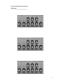
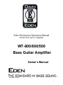
Eden Electronics Operation Manual
World Tour Series Amplifier
WT-800/600/500
Bass Guitar Amplifier
Owner’s Manual
Revised 3-5-2003
1
Forward
Congratulations on your purchase of the Eden WT-800/600/500 Bass Instrument
Amplifier. You have purchased what we feel is one of the finest bass amplifiers
in the world. The WT-800 produces 400 watts of pure power into 4 ohms (240
watts into 8 ohms) with 3db of dynamic headroom. The WT-600 produces 300
Watts per side @ 4 Ohms and 190 Watts @ 8 Ohms. The WT-500 produces 300
Watts @ 4 Ohms per side and 175 Watts @ * Ohms .The tube pre-amp section,
with its enhance control, powerful quasi-parametric tone control system, and
gentle auto -compression circuit allow you to achieve a wide array of sounds.
This compact, rack mountable package houses modular circuits made with
superior components and designed for years of trouble-free service.
Thank you for choosing Eden. Please take the time to review this manual and to
send i n your warranty registration card.
CAUTION!
Your ears are your most important piece of equipment. Unfortunately, they
cannot be replaced as easily as your other gear. Please take the following
warning seriously.
This product, when used in combina tion with a sound source and loudspeakers
or headphones, may be capable of producing sound levels that could cause
permanent hearing loss. DO NOT operate at high volume levels or at a level that
is uncomfortable. DO NOT place your ears next to the speakers. If you
experience any discomfort or ringing in the ears or suspect hearing loss, you
should consult a health care professional.
Please complete for your records:
Date of Purchase: __________________________
Model: ___________________________________
Serial Number: _____________________________
Dealer: ___________________________________
2
FRONT PANEL FEATURES
Frequency control – Provided for low,
Input Jack – Designed to accept a
mid, and high frequency ranges, these
controls select the frequencies you wish to
boost or cut.
standard ¼ inch mono phone plug. For best
results, use a high-quality, shielded cable to
connect your instrument to the amplifier.
Input Pad – By pushing the Pad switch in,
you engage a –12db pad, which will prevent
the system from being overdriven by highoutput instruments.
Boost/Cut Controls– Located beneath
each frequency selection control, these
controls will boost or cut the selected
frequency by 15 db. They are flat at their
12: 00 setting.
Treble – This is a traditional shelving-type
Pad Indicator – Lights to indicate that the
Gain Control – Regulates the first gain
tone control. It provides 15 db of boost or
cut. The knee of the filter is at
approximately, 2KHz. The control is flat at
the 12:00 position.
stage of the preamplifier and controls the
amount of signal available to the system.
EQ Clip Indicator – Flashes to indicate
Set Level Indicator – Lights to indicate
clipping within the tone control circuit of the
preamplifier. This should never be lit up.
pad is engaged.
that the preamp is sitting right on the sweet
spot of the gain balance and is at optimum
signal to noise as well as best overall head
room.
Compressor Indicator – Lights to
indicate that the signal has crossed the
threshold of the compression circuit and that
compression is taking place.
Compressor Bypass – Pushing the
switch in will disengage the compressor. It
will also turn on the set level light and turn
off the compressor active light.
Enhance Control – Called the “Magic
Knob” by some, this complex control
simultaneously boosts the very low-bass,
upper middle, and high frequencies while
putting a dip in the lower middle frequencies.
It is flat when set to its minimum level.
Tone Control Section
Master Level Control – Adjusts overall
system output.
Balance Control- This control adjusts
the balance between the left and right
channels of the amplifier. When the
Amplifier is in the Bi-Amp mode the
Balance control also adjusts the Hi and
Low balance.
Cross Over Control -This knob controls
the center frequency that the crossover
works at. This is a 12 dB per octave
crossover. Note. (This feature is not
available on the WT -500)
Stereo / Bi-Amp Mode switch - This
switch sits just behind the panel in the
stereo mode it moves forward when
switched to the Bi-Amp mode. You will
need to use a pen tip to engage the
switch.
Bass – This traditional shelving tone control
provides 15 dB of boost or cut at 30 Hz.
Quasi-Parametric Tone Control –
These three pairs of controls, with
overlapping frequencies, allow you to boost
or cut the tone at the desired frequency
center. The one octave fixed bandwidth
(Q=1) allows the controls to interact
smoothly and musically.
Bridge Mono Switch – This switch turns
the amplifier from stereo to bridged Mono.
This switch is recessed to prevent it being
turned on or off by accident. In mono bridge
this amplifier produces an 800 Watts RMS
output @ 8 Ohms. Please be very careful
when using the bridge mode you can
severely damage loudspeakers that are not
rated for this amount of power.
3
Headphone Jack – It accepts a standard
¼ stereo or mono headphone plug.
Output Limit Indicators – Lights to
indicate activity of the power amplifier
limiting circuit, which protects the speaker
system from severe distortion. This LED
indicates that the amplifier has reached its
maximum output level.
On/Off Switch – This switch turns the
system power on or off. The switch
illuminates to indicate the presence of
current prior to the fuse. The light in the
switch may flicker depending on local
voltage conditions. This is normal and
nothing to be concerned about
REAR PANEL FEATURES
Combination Power Cord Jack and
Fuse Holder – The removable power cord
is attached here. Pulling the holder out of
the top of the power inlet accesses the fuse
carrier. Your unit was shipped with a spare
fuse inserted in the fuse carrier. USE ONLY
THE SAME SIZE AND TYPE FOR
REPLACMENT. U.S. users should make
sure the fuse holder is installed so the “115
VOLTS” reads right side up. For Europe the
230 should be right side up. Some European
models come with a holder marked (FUSE)
they are configured for 230 / 240 only and
must be adapted by a service tech for U.S.
standard voltage. The standard fuse for U.S.
use is (10) Amp slow blow or time delay.
Do not use fast blow fuses.
Right Amp Out –This jack is also the
Low output when the Amp is in the Biamp mode. Low out not used on the
WT-500.
Bridged Mono Out- Use this jack only
for Mono bridging. Do not use any other
output in conjunction with this. Note
(The Minimum load in Bridged Mono
is 8 Ohms). Use caution this is a high
voltage and high power connection
point.
Mono Pre Tone Effects Send/Return –
These standard ¼ jacks allow you to
send and receive your signal to and
from external devices. The effects loop
is positioned post (behind) the
compressor and enhance control and
prior to the tone section.
Stereo Post Tone effects
Send/Return – This loop allows you to
send the effects in mono and return
them in stereo. The left return also
functions as a mono return if you are not
running stereo.
Recording Out – This fully balanced XLR
output allows you to send a post-EQ/premaster signal to a recording or sound
reinforcement mixing console. This output
is designed to allow use with phantom
powered systems.
D.I. Level – This Controls the level being
sent from the XLR balanced output jack.
Amp Outs left and Right – These
consist of two ¼ inch jacks and a 5 way
binding post on each channel. Or on newer
models the NL-4 connector replaces the
binding post. The jacks are wired in parallel.
The total speaker load impedance should
not exceed 4 ohms minimum for each
channel.
Left Amp out/ Hi out - This is also the
High out put when the amp is in Bi-Amp
mode. The Hi Out is not used on the
WT-500.
Ground Lift Switch – This switch lifts the
ground within the balanced output system to
allow you to eliminate excessive noise when
connected to external systems.
AUX In - The standard ¼ mono jack is
designed to accept the signal from an
external source such as a CD or cassette
player, drum machine, synth. module, etc.
The signal is summed prior to the master
volume control. The signal enters the
system post the tone controls. These jacks
can also be used to return a studio cue
signal, allowing the WT-800/600/500 to
4
provide you with your own headphone mix in
the studio.
Tuner Out Jack – This standard ¼ inch
jack is designed to provide a post-tube, pregain signal for connection to a tuner. It can
also be used to provide pre-tone signal to
other devices such as a direct box or
console.
made with high-quality shielded cables. The
use of speaker cables for line connections
will result in excess noise. Speaker
connections should be made with highquality 16 gauge or larger unshielded
speaker cables. We recommend 10 or 12
gauge cables. The use of shielded line or
instrument cables for speaker connections
can damage your amplifier. The speaker
cable should be as short as possible.
Cooling System – Your amplifier features
a thermostatically controlled fan, which will
switch on when the internal temperature
reaches 130 degrees F. In low volume
situations (into 8 Ohm loads) the fan may
not come on at all. The system also
features a high temperature thermal safety
system which will activate if the operating
temperature goes above 190 degrees F.
This circuit will turn the system off in the
event of overheating. It will automatically
reset itself as soon as the unit cools down to
a safe operating temperature. Usually it
takes from 1 to 5 minutes before the unit will
begin to operate again. (Note: the D.I. will
continue to operate normally even when the
amplifier is in thermal shut down only the
stage sound will be lost.) The system is set
up so that each amplifier is separately
protected.
OPERATING INSTRUCTIONS
MECHANICAL AND THERMAL
ISSUES – Your amplifier should always be
placed for operation away from sources of
moisture or heat. Care should be taken not
to obstruct the ventilation holes on the top
and sides of the unit. In the event of thermal
shutdown, you should eliminate the cause of
the thermal problem (poor ventilation,
speaker loads lower than 4 ohms)
immediately. The supplied rack ears can be
used to install your amplifier in a
conventional equipment rack for protection
during transportation.
ELECTRICAL requires 15 Amps of
correctly wired alternating current for proper
operations. The WT-600 and 500 require 12
Amps. The 800 should have 15 Amps
available.
CONNECTIONS – All line connections
(everything but the speakers) should be
TURN ON – We recommend turning your
system on with the master volume control
set to its minimum position. This will prevent
any unexpected signal from being sent to
your speakers. A crackling sound heard
through the system when it is first turned on
is the result of the tube warming up. This is
normal.
SETTING YOUR LEVEL – Effective use
of the gain control will ensure the best
signal-to-noise ratio. The Set Level,
Compressor, and EQ Clip indicators are all
provided to assist you in setting your level
correctly. You should begin the process
with your master control set to a low, or off
position, and your tone controls set flat.
While playing your instrument normally,
bring the gain control up until the set level
light or the compressor light winks on the
peaks that result from your strongest normal
attack. This will generally show up most on
your lower strings. You will use the
compressor light if the compressor is
engaged (enhance knob pushed in) and the
Set Level light if the compressor is disabled
(enhance knob pulled out). If more
compression is desired, increase the gain
control so the compressor light comes on
more readily. Having set your initial level,
you are now ready to proceed with setting
up your tone controls. Since tone
adjustments have an impact on the overall
preamp gain level, you may well need to
return to the gain control and repeat this
process once you have completed your EQ
adjustments.
SETTING UP YOUR EQ
Begin with all tone controls set flat and with
the Enhance Control set to its minimum
position. After setting your Gain level, bring
the Master control up to a moderate level.
Slowly bring the Enhance control up, playing
5
as you make each adjustment. Many
players find that there is a small amount of
boost on the Enhance control that will get
them very close to the sound they are after.
If it doesn’t, return it to its minimum or 0
position.
Overall bass and treble adjustments can be
made with the Bass and Treble controls.
These controls cover a fairly broad range of
the frequency spectrum. Many players use
these controls to compensate for acoustic
situations, relying on the Enhance and
Parametric controls to achieve their basic
sound.
Effective use of the quasi-parametric section
can help you boost and/or cut more narrow
sections. In each band, you will need to
“find” the frequency you wish to boost or cut.
The fastest way to do this is to boost the
Level control of one section significantly,
then rotate the Frequency control above it.
If you hear more of a frequency than you
like, leave the Frequency control at that spot
and reset the level to the desired amount of
boost. Conversely, if you hear a frequency
which is undesirable, leave the Frequency
control at that spot and reduce the Level
control to the desired amount of cut.
The frequencies that you will need to boost
or cut are dependent upon your instrument,
playing style, speaker cabinets, and venue.
Extreme settings of boost or cut are unlikely
to be necessary or helpful.
We are frequently asked to provide
suggested settings for various styles of play.
We have discovered though, that most of
our endorsers tend to set their EQ generally
flat, using varying amounts of the Enhance
Control. We encourage you to experiment
with different settings to obtain the sound
you desire. We have included some EQ
panel diagrams at the back of this manual to
help you record your settings.
EQ Clip Light – This indicator will flash if
clipping occurs in the EQ section of the
preamp. This can be remedied by
decreasing the amount of boost in the EQ
section or by decreasing the Gain control.
This light should never be on while playing.
Other EQ Considerations – If you find
yourself running out of amplifier headroom,
cut a little in the lower frequencies, which
require the most power from your amp.
Two areas are a frequent source of
frustration for bassists trying to achieve their
sound: frequency masking and frequency
enhancement. Frequency masking occurs
when other instruments (particularly cymbals
and electric guitars) obscure the important
upper harmonic content of your sound. As a
result, you find that the EQ settings that
were so perfect at home lack definition in a
live setting. On the other hand, the stage
settings that worked so well sound harsh
and/or thin in the absence of other
instruments. Frequency enhancement
results from cabinet placement and room
acoustics. A cabinet placed on the floor will
have the lower frequencies boosted by
about 3 db. Placement against a wall adds
another 3 db. A corner adds 3 db more.
Consequently you may find a surprising
boominess to your sound. Certain qualities
in the room itself can also enhance the lower
frequencies, further contributing to this
problem. Frequently this effect is more
noticeable in the audience than it is on
stage. Compensating for it may result in a
stage sound that may seem a little thin.
However the sound is actually quite full out
in front.
OTHER CONSIDERATIONS
Suggested Speaker Systems – Your
speaker system, should be chosen to
accommodate the characteristics of your
amplifier and your predominant application.
If you will only be using one cabinet per
side, a 4 Ohm model will draw the most
current from your amplifier. If you will
generally be using two cabinets, they should
both be 8 Ohm models so their combined
impedance will be 4 ohms. If you are
uncertain about your future needs always go
with the 8 Ohm speaker option so that you
can add another speaker later if you need
to.
Headphone Jack as a Line Driver –
On some occasions (such as high-volume or
outdoor situations) it may be desirable to
use the WT-800/600/500 along with an
6
additional power amplifier and added
cabinets. A standard shielded instrument
cable may be used to connect from the
headphone jack of the WT-800/600/500 to
an unbalanced input of a standard power
amplifier. This will provided a signal that is
post EQ and master volume controls,
allowing the entire system to be controlled
from the WT-800/600/500.
of several years is not at all uncommon.
Symptoms of tube failure include signal loss,
distortion, and increased noise. The tube is
easily replaced by removing the unit’s cover.
Always disconnect the power cord from
the back of the unit prior to removing the
cover. Gently remove the tube and replace
with a 7025 or high quality 12AX7 or
equivalent tube.
Using the WT -800/600/500 With out
Speakers -
Service – In the event of amplifier
This amplifier is designed to be used safely
with headphones only, without the loud
speaker plugged in. No harm will result from
using the amplifier in this fashion. This
allows the use of the unit for practice with
headphones and as a preamplifier with other
amplifiers.
MAINTENANCE
Your Eden amplifier has been designed to
require minimal routine maintenance.
Attention to the following areas will ensure
optimum performance of your amplifier.
Contact Point Cleaning – One of the
weakest links in most bass amplification
systems are the solderless connection
points where instruments, speaker cabinets,
effects, and other devices are connected to
the amplifier. (The most vulnerable of these
types of connection is the jack on your
instrument). In addition to contamination
from airborne pollutants, these points are
frequently assaulted by connectors that
have picked up debris from dirty stages,
cases, etc. These points should be cleaned
regularly with a cotton swab soaked in
denatured alcohol or a commercially
available deoxidant. Frequent cleaning of
the plugs on your cords is also
recommended.
Dust Removal – You should periodically
malfunction, or questions about your unit’s
operating features, you should contact your
Dealer, the factory or one of our authorized
service centers for assistance.
Please call our Customer Service dept. at
1-800-USSOUND
(1-800-877-6863)extension 5120
for more information or to obtain a Return
Authorization number and instructions for
factory returns.
Please ship Authorized Returns for
service to:
Eden Electronics
115 2 nd St.
Montrose, MN 55363
763-675-1890
Eden Electronics
C/O U.S. Music Corp.
444 E. Courtland Rd.
Mundelein, IL 60060
(847) 949-0444
(847) 949-8444(fax)
[email protected]
http://www.eden-eletronics.com
inspect the ventilation openings on the top
and sides of the unit to ensure that they
have not become blocked by accumulated
dust. Vacuum the openings to remove any
dust buildup.
Tube Replacement – Tube life varies
greatly depending upon use, vibration, and
tube quality. It is uncommon for a tube to
last less than a year in our circuits. Tube life
7
Your Favorite Tone Control
Settings______________
8