1
$/3+$
0,&526<67(06
5,*+7 )520 7+( 67$57
$/3+$
0,&526<67(06
5,*+7 )520 7+( 67$57
$/3+$
0,&526<67(06
5,*+7 )520 7+( 67$57
$/3+$
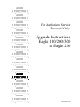
For Authorized Service
Personnel Only:
0,&526<67(06
5,*+7 )520 7+( 67$57
$/3+$
0,&526<67(06
5,*+7 )520 7+( 67$57
$/3+$
0,&526<67(06
Upgrade Instructions
Eagle 100/200/300
to Eagle 250
5,*+7 )520 7+( 67$57
$/3+$
0,&526<67(06
5,*+7 )520 7+( 67$57
$/3+$
0,&526<67(06
5,*+7 )520 7+( 67$57
$/3+$
0,&526<67(06
5,*+7 )520 7+( 67$57
$/3+$
0,&526<67(06
5,*+7 )520 7+( 67$57
$/3+$
0,&526<67(06
5,*+7 )520 7+( 67$57
$/3+$
0,&526<67(06
5,*+7 )520 7+( 67$57
$/3+$
0,&526<67(06
5,*+7 )520 7+( 67$57
PDI-00138-15, A00
© 2000 ALPHA MICROSYSTEMS
FIRST EDITION: July 2000
To re-order this document, request part number PDI-00138-15.
FCC Notice
This equipment has been tested and found to comply with the limits for a Class A digital device, pursuant to Part 15 of the FCC Rules.
These limits are designed to provide reasonable protection against harmful interference when the equipment is operated in a
commercial environment. This equipment generates, uses and can radiate radio frequency energy and, if not installed and used in
accordance with the instruction manual, may cause harmful interference to radio communications. Operation of this equipment in a
residential area is likely to cause harmful interference in which case the user will be required to correct the interference at his own
expense.
Canadian Department of Communications Compliance Statement
This equipment does not exceed Class A limits per radio noise emissions for digital apparatus set out in the Radio Interference
Regulations of the Canadian Department of Communications. Operation in a residential area may cause unacceptable interference to
radio and TV reception requiring the owner or operator to take whatever steps are necessary to correct the interference.
Avis de Conformité aux Normes du Ministère des Communications du Canada
Cet équipment ne deapsse pas les limits de Classe A d'émission de bruits radioélectriques pour les appareils numeriques tels que
prescrites par le Règlement sur le brouillage radioélectrique établi par le ministère des Communications du Canada. L'exploitation faite
en milleu résidential peut entrainer le brouillage des réceptions radio et tele, ce qui obligerait le propriétaire ou l'opératour à pendre les
dispositions nécessaires pour en éliminer les causes.
Battery Warning
CAUTION: Danger of explosion if battery is incorrectly replaced. Replace only with the same or equivalent type recommended by the
manufacturer. Discard used batteries according to the manufacturer's instructions.
ATTENTION: Il y a danger d'explosion s'il y a replacement incorrect de la batterie. Remplacer uniquement avec une batterie du même
type ou d'un type recommandé par le constructeur. Mettre au rébut les batteries usagées conformément aux instructions du fabricant.
For AM-3500-E100, -E200, -E300, -E400, -E500 and AM-990-01 systems replace battery with Panasonic or Ray-O-Vac BR2325 only.
For AM-3500-E250, AM-3500-E450, AM-3500-E550, AM-3500-6000, and AM-990-04 systems, replace batteries with Panasonic or
Ray-O-Vac BR1225 only. Use of other batteries may present a risk of fire or explosion. Replacement batteries may be ordered from
your authorized Alpha Micro reseller.
Safety Warning
This computer contains no user-configurable components that require opening the computer case. Because the power supply in this
computer is capable of outputting high current levels hazardous to your safety, the computer case should only be opened by an
authorized service technician.
Cet ordinateur ne contient aucune pièce configurable par l’utilisateur qui nécessite l’ouverture du boitier. L’alimentation de cet
ordinateur peut preduire des nivaeux de tensions dangereux, le boitier ne devrait donc être ouvert que par un technician autoriaé.
SOFTWARE SECURITY DEVICE IDENTIFICATION NUMBER: _________________
The Alpha Micro Software Security Device (SSD) is a customized integrated circuit that personalizes the computer, providing identity
verification for it. Certain Alpha Micro and non-Alpha Micro software may require that your computer contain an SSD in order to run
software that has been customized to run only on your computer.
Please enter the identification of your SSD above. The SSD identification number should be on your computer ID label under "SSD
Serial No." (Another way of finding the number is to look at the SSD itself. The SSD is located in an integrated circuit location on the
CPU board; its identification number is printed on the SSD itself.) Software vendors may ask you for the SSD number if they are
customizing software to run only on your computer.
This document may contain references to products covered under the following U.S. Patent Number(s): 4,530,048
ALPHA MICROSYSTEMS
2722 Fairview Street
Santa Ana, CA 92704
Table of Contents
CHAPTER 1 -INTRODUCTION
1
ABOUT THIS DOCUMENT
Graphic Conventions
1
2
CHAPTER 2 -COMPATIBILITY
SOFTWARE COMPATIBILITY
HARDWARE COMPATIBILITY
SCSI TAPE AND HARD DISK DRIVE REQUIREMENTS
The SCSI Floppy Drive
SCSI Tape Drives
SCSI Hard Disk Drives
SCSI-2 Dispatcher
CHAPTER 3 -UPGRADING EAGLE 250 ON-BOARD MEMORY
ELECTRONIC EQUIPMENT HANDLING PRECAUTIONS
INSTALLING MEMORY
Setting Memory Jumpers
Changing Memory SIMMs
3
3
3
3
4
4
4
4
5
5
6
7
8
CHAPTER 4 -CONFIGURING THE AM-138-10
9
AM-138-10 BOARD ILLUSTRATION
AM-138-10 Jumpers
AM-138-10 Connectors
THE CMOS MENU
ETHERNET PORT
REMOTE RESET CAPABILITY
INSTALLING THE SSD CHIP
ON-BOARD SERIAL PORTS
FRONT PANEL STATUS DISPLAY CODES
SERIAL UPS MONITORING
9
11
12
12
13
13
14
14
15
15
CHAPTER 5 -BEGINNING AN EAGLE 250 UPGRADE
ELECTRONIC EQUIPMENT HANDLING PRECAUTIONS
STEP 1 - PROTECTING YOUR DATA
STEP 2 - INSTALL THE CORRECT VERSION OF AMOS
STEP 3 - UPGRADE CIRCUIT BOARDS AND PERIPHERALS
STEP 4 - CREATE A NEW SYSTEM MONITOR
Eagle 250 Upgrade Instructions, Rev. A00
17
17
18
18
18
19
Page ii
Table of Contents
STEP 5 - CREATE A NEW SYSTEM INITIALIZATION FILE
STEP 6 - CREATE NEW SUBSYSTEM DISK DRIVERS
STEP 7 - NETWORK CONFIGURATION
STEP 8 - PROTECT YOUR DATA AGAIN
STEP 9 - INSTALL THE EAGLE 250 HARDWARE
CHAPTER 6 -EAGLE 100 UPGRADE HARDWARE INSTALLATION
PREPARING FOR THE UPGRADE
REMOVING THE CHASSIS COVER
REMOVING THE AM-137 BOARD
PREPARING THE AM-138-10 BOARD
INSTALLING THE NEW REAR PANEL AND AM-138-10 (OLD STYLE CHASSIS)
INSTALLING THE NEW REAR PANEL AND AM-138-10 (NEW STYLE CHASSIS)
HOOKING UP THE AM-138-10
FINISHING UP
CHAPTER 7 -EAGLE 200/300 UPGRADE HARDWARE INSTALLATION
PREPARING FOR THE UPGRADE
REMOVING THE CHASSIS COVER
REMOVING THE ROADRUNNER BOARD
Removing a Vertically-mounted Roadrunner
Removing a Horizontally-mounted Roadrunner
REMOVING THE AM-319 BOARD
PREPARING THE AM-138-10 BOARD
INSTALLING THE NEW REAR PANEL AND AM-138-10 (OLD STYLE CHASSIS)
INSTALLING THE NEW REAR PANEL AND AM-138-10 (NEW STYLE CHASSIS)
HOOKING UP THE AM-138-10
FINISHING UP
CHAPTER 8 -TESTING THE NEW SYSTEM
19
21
22
22
22
23
23
23
24
26
26
28
29
32
33
33
33
34
34
37
38
39
39
41
42
46
47
RUNNING A SELF-TEST
SET YOUR CMOS CONFIGURATION AND BOOT
RENAMING THE SYSTEM MONITOR AND INITIALIZATION FILES
BACK UP AND MAKE A NEW WARM BOOT TAPE
ADDITIONAL DOCUMENTATION
APPENDIX A -SCSI TERMINATION
47
47
48
48
48
49
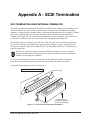
SCSI TERMINATION USING EXTERNAL TERMINATOR
ATTACHING EXTERNAL DEVICES
TERMINATOR POWER
49
50
50
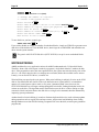
APPENDIX B -READ-AHEAD AND WRITE BUFFERING
51
READ-AHEAD
51
Eagle 250 Upgrade Instructions, Rev. A00
Table of Contents
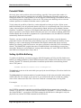
Controlling Read-Ahead
WRITE BUFFERING
Potential Pitfalls
Setting Up Write Buffering
FINAL NOTES
Eagle 250 Upgrade Instructions, Rev. A00
Page iii
51
52
53
53
54
LIST OF ILLUSTRATIONS
Figure 3-1: ESD Wrist Strap.................................................................................................................... 5
Figure 3-2: AM-138-10 SIMM Module Installation................................................................................. 6
Figure 3-3: JP7 Memory Jumpers............................................................................................................ 7
Figure 4-1: AM-138-10 Board............................................................................................................... 10
Figure 4-2: SSD Chip Removal Tool..................................................................................................... 14
Figure 6-1: Deskside Chassis Cover Removal ....................................................................................... 24
Figure 6-2: AM-137 Mounting Bracket Removal .................................................................................. 25
Figure 6-3: Removing the Old Rear Panel ............................................................................................. 27
Figure 6-4: Eagle 250 Rear Panel (Old Style Chassis) ........................................................................... 30
Figure 6-5: Eagle 250 Rear Panel (New Style Chassis) .......................................................................... 31
Figure 7-1: Deskside Chassis Cover Removal ....................................................................................... 34
Figure 7-2: Roadrunner Mounting Bracket, Early-Model Eagles............................................................ 35
Figure 7-3: Roadrunner Removal, Early-Model Eagles.......................................................................... 36
Figure 7-4: Roadrunner Removal, Late-model Eagles............................................................................ 37
Figure 7-5: AM-319 Mounting Bracket Removal .................................................................................. 38
Figure 7-6: Removing the Old Rear Panel ............................................................................................. 40
Figure 7-7: Eagle 250 Rear Panel (Old Style Chassis) ........................................................................... 44
Figure 7-8: Eagle 250 Rear Panel (New Style Chassis) .......................................................................... 45
Figure A-1: Active External Terminator Installation .............................................................................. 49
Eagle 250 Upgrade Instructions, Rev. A00
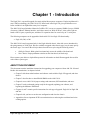
Chapter 1 - Introduction
The Eagle 250 is a powerful upgrade for certain Alpha Microsystems computers. Employing Motorola’s
new ColdFire technology, the AM-138-10 CPU board used in the Eagle 250 gives performance never
before available in an Alpha Micro entry level computer.
The AM-138-10 board includes a Motorola ColdFire CPU, one or two memory SIMMs for up to 256MB
of memory, 10BaseT Ethernet interface, and either a narrow or Wide SCSI bus. It also offers eight onboard serial I/O ports, a parallel port, and three I/O expansion slots for a total of up to 32 serial ports.
The following computers can be upgraded with the AM-138-10 to Eagle 250 functionality:
• Eagle 100, 200, or 300
The AM-138-10 board is supported only in the Eagle deskside chassis, either old or new (introduced in
the spring/summer of 1998) style. Kits are available to upgrade either chassis type, but you must specify
the chassis type. You can tell the old style chassis from the new style using the following criteria:
•
•
Old Style Chassis: Black plastic horizontal strip across the middle of the front bezel
New Chassis: Purple pushbutton switches on the front bezel (no black strip)
Please contact your dealer or Alpha Microsystems for information on the different upgrade kits used for
each of these system types.
ABOUT THIS DOCUMENT
This document contains installation instructions for upgrading your computer with an AM-138-10 board.
Besides this introduction, its chapters include:
• Chapter 2 talks about what hardware and software works with the Eagle 250 upgrade, and what
doesn’t.
• Chapter 3 describes how to install RAM SIMMs on the AM-138-10.
• Chapter 4 covers AM-138-10 jumper settings and connectors, SSD installation, and more.
• Chapter 5 leads you through getting ready for the upgrade, updating your software, and
beginning the hardware installation.
• Chapters 6, and 7 contain specific instructions for each type of upgrade: Eagle 100 or Eagle 200
and 300.
• Chapter 8 tells you how to test the new configuration and close the chassis.
• Appendices discuss important SCSI bus termination issues and using the read-ahead and writecaching options.
Eagle 250 Upgrade Instructions, Rev. A00
Page 2
Chapter One
In addition to this manual, you should have received a copy of the Eagle 250 Installation and
Technical Manual, DSO-00222-00. Keep that book handy during the upgrade procedure; these
instructions refer to it several times. It also includes details on the features and performance of
the AM-138-10 board and Eagle 250, and environmental and electrical requirements.
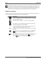
Graphic Conventions
Like other Alpha Micro documents, this manual uses some standard symbols and special typefaces to
make our examples and explanations easier to read and understand:
Symbol
Description
This means STOP!, and signals an important warning or restriction.
Be sure to read the text next to this symbol carefully, as it could help
you avoid serious problems.
This marks a hint—a shortcut or an easier way to do something.
This indicates a note: information which relates to the current topic,
and may be important for you to remember.
Text
We show characters the computer displays on your screen, such as
prompts and information messages, in this typeface.
TEXT
In examples, we use this typeface for the characters you type on your
keyboard.
KEY
CTRL
/C
This symbol tells you to press the indicated key. For example: DIR
ENTER tells you to press the ENTER key at the end of the DIR
command.
This combination of symbols tells you to hold down the first key and
press the second key. For example, to type a CTRL /C (Control-C),
press the CTRL key and, while holding it down, type a C.
Eagle 250 Upgrade Instructions, Rev. A00
Chapter 2 - Compatibility
Before you proceed with your upgrade, it’s important to make sure you have all the hardware and
software you’ll need. This chapter discusses the hardware and software compatibility issues that may
arise during your Eagle 250 installation.
SOFTWARE COMPATIBILITY
To be compatible with the AM-138-10 CPU board, the operating system must be AMOS 2.3A, PR 06/00
or later. You cannot use AMOS 1.x with the AM-138-10.
HARDWARE COMPATIBILITY
With the following exceptions, the I/O and other peripheral circuit boards supported in other Eagle series
computers are compatible with the AM-138-10 board in your new Eagle 250. The exceptions are:
• The AM-219 floppy controller board is not supported. A SCSI floppy drive is used instead (see
below).
• The AM-338 RJE controller SIMM is not supported.
For serial I/O, while we recommend the AM-318-10 as the best combination of features and port density,
the AM-314, AM-318-00, and AM-318-02 are also supported.
SCSI TAPE AND HARD DISK DRIVE REQUIREMENTS
The SCSI controller on the AM-138-10 provides two bus interfaces. One is a 50-pin SCSI bus interface,
the same as on the Roadrunner 030 and 040, Eagle 100, 200, 300, 400, 500, and 550, and the AM-4000.
The second is a 68-pin Wide SCSI bus interface, the same as on the Eagle 450, AM-6000 and AM-7000.
All devices must connect to one of the two busses; the other connector cannot be used. You cannot attach
peripherals to both busses in the same computer!
Either SCSI bus will support the SCSI disk and tape devices in your current Eagle. In addition, you can
attach Wide SCSI-2 drives to either bus, using the appropriate adapter to attach them to the narrow bus.
The Eagle 250 upgrade kit comes in both narrow and Wide SCSI-2 versions. The narrow version uses
your existing SCSI cable and connectors; the Wide SCSI-2 version includes a new SCSI cabling items.
For complete information on bus configuration, devices supported, and important termination rules,
please refer to Chapter 3 of the Eagle 250 Installation and Technical Manual. The following sections
briefly discuss some bus/device issues.
Never attach a device to or remove one from the SCSI bus while system power is on. The Eagle
250 SCSI bus uses tolerant active negation, which increases the probability that “hot plugging” a
SCSI device will damage the device, the SCSI controller, or both.
Eagle 250 Upgrade Instructions, Rev. A00
Page 4
Chapter Two
The SCSI Floppy Drive
Most previous Alpha Micro computers, including the Eagle you’re upgrading from, used a separate
floppy disk controller to interface to a diskette drive. The Eagle 250 does not support any of the floppy
controllers used in previous Alpha Micro systems (the AM-210, 212, 214, or 219). Instead, it can use a
SCSI floppy drive, the AM-212-20.
The AM-212-20 attaches to the SCSI cable like any other SCSI device. Though it is a 3.5” diskette drive,
it uses a 5.25” mounting bay.
SCSI Tape Drives
Any SCSI tape drive which works in your current Eagle will also work in your upgraded Eagle 250. No
firmware revisions are necessary.
In order to warm boot from a Tandberg streaming tape drive, make sure you enter it as the alternate boot
unit ID in the CMOS Configuration Menu.
SCSI Hard Disk Drives
For optimum performance, use Wide SCSI-2 drives attached to the Wide (68-pin) SCSI connector.
Mixing SCSI-1, SCSI-2, and Wide SCSI-2 disks on the same bus tends to degrade performance and is
not recommended.
SCSI-2 Dispatcher
You must define a SCSI dispatcher in the system initialization command file. AMOS uses the dispatcher
to communicate with the SCSI controller chip. The dispatcher handles all communications with the SCSI
controller chip.
There are two versions of the SCSI dispatcher for the AM-138-10 board:
• SCZ138.SYS is a high-performance version of the SCSI dispatcher, which supports command
queuing, synchronous transfers, multi-threaded operations, and scatter-gather operations.
• SIM138.SYS is a simplified version of the SCSI dispatcher and does not support the high
performance features supported in SCZ138.SYS. You would use SIM138.SYS when making
warm boot tapes and for temporary situations with computers which have not had the AMOS
PIC code installed.
While both of these dispatchers support both narrow and Wide SCSI-2 devices, using the SCZ138.SYS
dispatcher increases system performance greatly, and allows you to use DCACHE and write cache
efficiently. SCZ138.SYS also supports several option switches to let you modify its performance, as
described in Chapter 5.
Please refer to Chapter 5 for instructions on enabling the Eagle 250’s SCSI dispatcher.
Eagle 250 Upgrade Instructions, Rev. A00
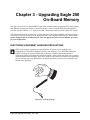
Chapter 3 - Upgrading Eagle 250
On-Board Memory
The AM-138-10 has two on-board SIMM (single inline memory module) expansion slots, which support
60ns DRAMs. Because the memory is located on-board, it can be accessed much faster than memory
accessed over the VME bus—i.e., AM-730 and AM-740 memory boards used with earlier CPU boards.
The following procedures describe how to install and remove the memory SIMMs, and set the memory
size jumpers. They are referred to in the appropriate place in the upgrade instructions in Chapters 6and 7.
Do not attempt install any SIMM until you reach the appropriate place in the installation procedure
for your configuration.
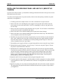
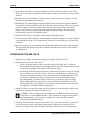
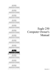
ELECTRONIC EQUIPMENT HANDLING PRECAUTIONS
While your computer's hardware is exposed and the AC power cord is unplugged, the
components are vulnerable to damage caused by static discharge. Your body and clothing are
capable of storing an electrical charge that can damage or destroy unprotected electronic
components. Before you handle any computer hardware, make certain your work area is properly
protected against static discharge. There are a number of commercially available static protection
devices, like the wrist strap shown below, designed specifically to protect your equipment from
harmful static discharge.
Figure 3-1: ESD Wrist Strap
Eagle 250 Upgrade Instructions, Rev. A00
Page 6
Chapter Three
INSTALLING MEMORY
The Eagle 250 supports from 4MB to 256MB of main memory: either one or two memory SIMMs of
4MB, 8MB, 16MB, 32MB, 64MB, or 128MB. Use 60ns SIMMs only; 70ns SIMMs will not work.
Unlike the AM-6000 and AM-7000, SIMMs do not have to be installed in pairs: you can use either one
or two SIMMs; if you use two, they do not have to be of equal size. For example, you can install one
32MB SIMM and one 16MB SIMM for a total of 48MB of memory.
The memory SIMMs install in connectors J10 and J11. See Figure 4-1 for the location of these
connectors. If you’re installing only one SIMM, it goes in J10. If you’re installing two SIMMs of
unequal capacity, the larger one goes in J10.
To install memory expansion SIMMs on the AM-138-10 board, use this procedure:
Remember, don’t follow this procedure until you’re at the proper place in the installation process
for your upgrade.
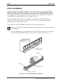
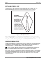
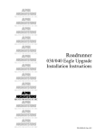
1. Insert one SIMM (the larger if the SIMMs aren’t of equal capacity) in connector J10. Align pin-1
at the notched end of the SIMM module with pin-1 on the connector, as in Figure 3-2.
MAKE SURE THIS CURVE
IN THE SIMM CARD ALIGNS
WITH PIN-1 IN THE SIMM
CONNECTOR.
SIMM (SINGLE INLINE
MEMORY MODULE)
RETAINER
CLIP
RETAINER
CLIP
SIMM
CONNECTOR
PIN-1 INDICATOR
Figure 3-2: AM-138-10 SIMM Module Installation
Eagle 250 Upgrade Instructions, Rev. A00
Upgrading Eagle 250 On-board Memory
Page 7
2. Insert the SIMM module into the connector at a slight angle.
Rotate into the upright position.
The SIMM will engage the metal retainer clips and click into position, locking the SIMM in
place.
3. If you are using two SIMMs, repeat steps 1 and 2 for the second one, at connector J11.
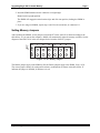
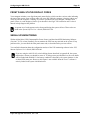
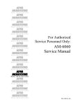
Setting Memory Jumpers
1
2
4
1
2
4
BANK1
BANK0
JP7
After installing the SIMMs, set the jumpers at location JP7 on the AM-138-10 board according to the
table below. As you turn on the computer, AMOS will automatically make the memory available. See the
diagram of the AM-138-10 in the next chapter for the location of the JP7 jumpers.
Figure 3-3: JP7 Memory Jumpers
The Bank 0 jumpers apply to the SIMM in J10; the Bank1 jumpers apply to the SIMM, if any, in J11.
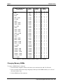
The correct jumper settings for each possible memory combination are shown in the table below. X
indicates the jumper is installed; O indicates it is not.
Eagle 250 Upgrade Instructions, Rev. A00
Page 8
Chapter Three
Memory Module Size
Combinations:
4MB
2 x 4MB
8 MB
8MB + 4MB
2 x 8MB
16MB
16MB + 4MB
16MB + 8MB
2 x 16MB
32MB
32MB + 4MB
32MB + 8MB
32MB + 16MB
2 x 32MB
64MB
64MB + 4MB
64MB + 8MB
64MB + 16MB
64MB + 32MB
2 x 64MB
128MB
128MB + 4MB
128MB + 8MB
128MB + 16MB
128MB + 32MB
128MB + 64MB
2 x 128MB
Total
Memory
4MB
8MB
8 MB
12MB
16MB
16MB
20MB
24MB
32MB
32MB
36MB
40MB
48MB
64MB
64MB
68MB
72MB
80MB
96MB
128MB
128MB
132MB
136MB
144MB
160MB
192MB
256MB
Bank0
Settings
1
2
4
X X X
X X X
O X X
O X X
O X X
X O X
X O X
X O X
X O X
O O X
O O X
O O X
O O X
O O X
X X O
X X O
X X O
X X O
X X O
X X O
O X O
O X O
O X O
O X O
O X O
O X O
O X O
Bank1
Settings
1
2
4
O
O
O
X
X
X
O
O
O
X
X
X
O
X
X
O
O
O
X
X
X
O
X
X
X
O
X
O
O
O
X
X
X
O
X
X
X
O
X
O
O
X
O
O
O
X
X
X
O
X
X
X
O
X
O
O
X
X
X
O
O
O
O
X
X
X
O
X
X
X
O
X
O
O
X
X
X
O
O
X
O
Table 3-1: AM-138-10 Memory Module Jumper (JP7) Settings
Changing Memory SIMMs
To remove a SIMM from its connector:
1. Power down the computer. Remove the chassis cover and access the AM-138-10 board.
2. Press out on the metal retainer clips and gently tilt the top of the SIMM module, so it is free of
the metal retainer clips.
3. Lift the SIMM out of the connector
Eagle 250 Upgrade Instructions, Rev. A00
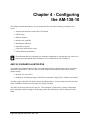
Chapter 4 - Configuring
the AM-138-10
This chapter contains information you may need both before and after installing your Eagle 250. It
covers:
• Jumpers and connectors on the AM-138-10 board
• CMOS setup
• Ethernet interface
• Remote reset capability
• Installing the SSD chip
• On-board serial ports
• Front panel status display codes
• UPS monitoring information
We recommend that you safeguard your computer components by insuring that your work area is
properly protected against static discharge. For more information, refer to Chapter 3.
AM-138-10 BOARD ILLUSTRATION
Your AM-138-10 board has been factory tested and shipped with its configuration jumpers set in their
standard default positions. There are only two areas on the board which may require you to change
jumper settings:
• Memory size select (JP7)
• Enabling or disabling the supply of SCSI bus termination voltage (JP3)—default set at enabled.
All other jumpers should be left in their factory-installed positions. You may want to check your board
before installation to make sure all jumpers are properly installed.
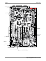
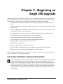
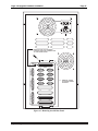
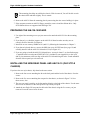
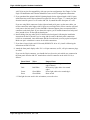
The AM-138-10 board is shown in Figure 4-1. The illustration is followed by a jumper configuration
table, showing the default setting for each jumper, and a table defining the various connectors on the
board.
Eagle 250 Upgrade Instructions, Rev. A00
Page 10
Chapter Four
Remote reset
jumper
On-board
serial ports
SSD goes
here
Wide SCSI
connector
Narrow SCSI
connector
Serial I/O
expansion slots
Memory
Remote reset
adapter attaches
here.
First memory SIMM
Second memory SIMM
Figure 4-1: AM-138-10 Board
Eagle 250 Upgrade Instructions, Rev. A00
Configuring the AM-138-10
Page 11
AM-138-10 Jumpers
Jumper
Number
JP1
Jumper Name
RR-EN
Default
Setting
out
JP2
Level7 Select
UPS
JP3
20
16
TERMPWR
IN
out
EN
DISC
Memory Size
Select
32
16
25
20
33
33
50
66
SP
IN
See Table 3-2
JP5
JP6
JP7
JP8
JP9
out
out
out
out
IN
out
out
IN
out
Notes
When IN, enables remote reset through serial
port 0 (this is not supported through AM-90
card); when out, allows remote reset cable
attachment at P8. See page 13.
3-pin jumper; set to two pins at UPS side. When
set to FP, front panel Turbo switch enables
Level7 diagnostic. Not user configurable.
Ethernet bus clock select. Not user configurable.
SCSI bus termination voltage,
EN = Enabled, DS = Disabled. User may change.
Not user configurable
Memory size configuration. Installer must
configure.
Not user configurable.
Not user configurable.
Table 4-1: AM-138-10 Board Jumper Configuration
Eagle 250 Upgrade Instructions, Rev. A00
Page 12
Chapter Four
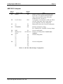
AM-138-10 Connectors
The following table provides a brief overview of the connectors on the AM-138-10 board.
Connector
Number
Connector
Name
Connector
Type
J1
J2
J4
J7
J8
J9
J10
J11
J13
UPS
Parallel port
Ethernet
Ports 10-17
Ports 20-27
Ports 30-37
Bank 0
Bank 1
SCSI-2 Wide
9-pin
25-pin
TPI
42-pin
42-pin
42-pin
SIMM
SIMM
68-pin
P1
P2
P3
P4
P5
40-pin
40-pin
Molex
Molex
P6
P7
Ports 0 - 3
Ports 4 - 7
Power
Power
Option
Connector
Program
SCSI-2
P8
Run
Disk
2-pin
2-pin
Power
2-pin
Reset
2-pin
26-pin
20-pin
P9
P10
50-pin
Cable Description and How to Use
Cable pin-1 up, use keyed cable
Cable pin-1 up, use keyed cable
RJ-45.
Serial expansion
Serial expansion
Serial expansion
First memory SIMM
Second memory SIMM
Cable pin-1 down, use keyed cable. Cannot use
both this and P7.
First four on-board ports
Second four on-board ports
For +5V, +12V, -12V and GND
For +5V and GND
FOR FUTURE USE
FOR FACTORY USE ONLY
Cable pin-1 down, use keyed cable. Cannot use
both this and J13.
Run light if using 20-pin front panel display at P10
Disk activity light if using 20-pin front panel
display at P10
Power light if using 20-pin front panel display at
P10
Optionally, connect PDB-10323-00 to inner pin.
Front panel status display (AM-966-10)
Front panel status
Table 4-2: AM-138-10 Connectors
THE CMOS MENU
The Eagle 250 does not use boot ID switches; instead it has a CMOS configuration menu to let you
choose primary and secondary boot devices, as well as set other system options, such as the system
monitor file to use. After installing the AM-138-10, as described later in this document, you can access
the CMOS menu before booting the new computer for the first time. You’ll need to do this if you aren’t
using the default boot configuration. The default settings are:
• Primary boot device: Disk at SCSI ID 0
• Secondary boot device: Streamer tape at SCSI ID 3
Eagle 250 Upgrade Instructions, Rev. A00
Configuring the AM-138-10
Page 13
• Monitor file name: AMOS32.MON
• Initialization file name: AMOS32.INI
• Network interface: TPI
• Serial port 0 speed: 19.2K baud
• Boot messages on console?: Yes
For information on changing the CMOS configuration , please refer to Chapter 4 of the Eagle 250
Installation and Technical Manual.
ETHERNET PORT
The AM-138-10 board contains a 10BaseT Ethernet connector. To use this Ethernet port, you'll need
Alpha Micro's networking software, AlphaTCP, which is included with AMOS 2.3A and later. There are
two software drivers for the AM-138-10's Ethernet port: AM138.LDV, which is only TCP compatible
(and supports ITC tunneling) and AM138.NDV, which is AlphaNET compatible. In most configurations,
AM138.LDV provides better performance.
For instructions on configuring AMOS to use the AM-138-10 Ethernet port, please see Chapter 5.
Additional information on configuring your networking software and hardware is in the AlphaTCP
Administrator’s Guide, DSO-00187-00.
REMOTE RESET CAPABILITY
The AM-138-10 board has an option to enable remote hardware reset, either through serial port 0, or by
using the Remote Reset Adapter, PDB-10323-00.
You cannot use remote reset through port 0 if port 0 uses an AM-90 card for its back panel
connection; the AM-90 does not support this feature. If you use an AM-90, which we
recommend, you must use the Remote Reset Adapter if you want remote reset ability.
To enable remote reset through serial port 0, you must do two things:
1. Install the JP1 jumper. The factory default is not installed.
2. Connect a push-button switch between pin-1 and pin-7 (signal ground) at the terminal end of the
terminal cable attached to serial port 0.
Once you’ve enabled remote reset, you can reset the computer by activating the push-button switch.
The remote reset adapter allows you to reboot the computer from anywhere in your facility by wiring an
external switch to the location you want. To install the remote reset adapter, follow the instructions in
PDI-10323-00. The JP1 jumper must not be installed. Attach the adapter’s single-wire connector to the
connector labeled RESET at location P8. Attach it to the pin away from the edge of the board.
Eagle 250 Upgrade Instructions, Rev. A00
Page 14
Chapter Four
INSTALLING THE SSD CHIP
You must remove the SSD chip from your existing computer and install it in on the AM-138-10.
Removing the SSD requires a special tool. See the illustration below for more information.
WARNING!
The SSD chip and boot
PROM on the AM-138
board require a
specialized tool for
their removal. If you
attempt to remove
the SSD chip or
boot PROM using
a screwdriver or
pocketknife, you
could easily damage
both the chip and the
socket. This type of chip
extraction tool is available
at retail stores specializing
in electronic components.
Figure 4-2: SSD Chip Removal Tool
Before installing the SSD chip in the AM-138-10, write the SSD number in a secure place for future
reference. Install the SSD at its clearly marked socket at U34 (see Figure 4-1), by inserting and pressing
down gently on the chip. Make sure you align pin-1 on the SSD chip with the SSD socket.
ON-BOARD SERIAL PORTS
The AM-138-10 contains eight on-board serial ports. These are standard, fully functional ports, to which
you can attach any supported terminal, printer, or modem. When you define these terminals, use the
A31810 interface driver, as described in Chapter 5. Port 0 is the system boot port.
You can also use the AM318.IDV interface driver for the on-board serial ports. However, since
this driver doesn’t support full modem control, we recommend the A31810.IDV driver.
In any upgrade, these ports can use either DB-9 connectors or AM-90 cards with RJ-45 connectors on the
back panel, depending on the internal cable kit ordered. The AM-90 card has the advantage of lightning
protection. The ports support full modem control with either cabling option, as long as they use the
A31810 interface driver.
Eagle 250 Upgrade Instructions, Rev. A00
Configuring the AM-138-10
Page 15
FRONT PANEL STATUS DISPLAY CODES
Your computer includes a two-digit front-panel status display, which can show various codes indicating
the state of the system. Some of these codes will occur only while the computer is booting; others may
occur any time the computer is running. If you have a problem with your computer, check the front
panel; if there is a code displayed, look it up in the table in the Eagle 250 Installation and Technical
Manual to help diagnose the problem.
A separate set of codes appears on the front panel during the system self-test. Those codes are
listed in the System Self-test User’s Guide, DSO-00157-00.
SERIAL UPS MONITORING
With an Alpha Micro UPS (Uninterruptible Power Source) and the related UPS Monitoring Software
(Version 1.3(176) or later) installed, you can monitor the UPS from any terminal on the system. If any
problem arises, you can check the front panel status code, as described in the previous section.
You can find information about the configuration and use of the UPS monitoring software in the UPS
Monitor Software User's Guide, DSS-10394-00.
If you are using the AM-138-10's write buffering feature described in Appendix B, the system
monitor has a feature you should be aware of. To help prevent possible data loss, the write buffer
will be flushed and disabled if a low battery condition is detected by the system monitor via the
on-board UPS status port. However, this feature is not available when the Level 7 software is
actively loaded in the system initialization file.
Eagle 250 Upgrade Instructions, Rev. A00
Chapter 5 - Beginning an
Eagle 250 Upgrade
When you upgrade your computer to an Eagle 250, it’s important that you perform the proper hardware
and software steps in the correct order, taking all the necessary precautions to protect your data in case of
a problem. Here is a brief summary of the steps you must follow to complete your upgrade:
1. Safeguard your data by performing a complete backup and preparing and testing a warm boot
tape.
2. Install the correct version of AMOS, following the instructions detailed in the appropriate AMOS
Release Notes.
3. If you are updating other components, such as disk drives or serial I/O boards, you may want to
install them before the AM-138-10 upgrade.
4. Use MONGEN to create a new monitor file, called AM138.MON, for the AM138-10 board.
5. Use FIXLOG to create new disk drivers for any subsystem disks.
6. Create a new initialization file for the Eagle 250, called AM138.INI.
7. If your computer is on a network, modify the network configuration file.
8. Back up DSK0: and prepare and test a warm boot tape.
9. Install the Eagle 250 hardware.
10. Turn the computer back on and perform self-test.
11. Set your CMOS configuration options to match the new system hardware and software.
12. Boot up your system. Ensure that all peripherals are working correctly.
The rest of this chapter describes steps 1 - 8, then tells you where to look in this manual for instructions
on step 9. Steps 10 - 12 are covered in Chapter 8.
ELECTRONIC EQUIPMENT HANDLING PRECAUTIONS
While your computer's hardware is exposed and the AC power cord is unplugged, the components
are vulnerable to damage caused by static discharge. Your body and clothing are capable of
storing an electrical charge that can damage or destroy unprotected electronic components. Before
you handle any computer hardware, make certain your work area is properly protected against
static discharge. There are a number of commercially available static protection devices, like the
wrist strap shown in Chapter 3, designed specifically to protect your equipment from harmful
static discharge.
Eagle 250 Upgrade Instructions, Rev. A00
Page 18
Chapter Five
STEP 1 - PROTECTING YOUR DATA
Perform a Complete Back Up
When doing a major upgrade to a computer, you want to be absolutely sure you have a recent and
complete system backup. Although it is very unlikely that data stored on your hard disk drive would be
corrupted when upgrading your computer, you should be prepared for anything. Before you loosen the
first screw or download any new software, make sure all your data is copied onto some form of
backup media. Make certain you are able to read the backed-up data; be absolutely sure it is readable
and restorable.
Create a Warm Boot Tape
A warm boot tape allows you to boot the computer when you cannot do so from the hard disk drive.
When doing an Eagle 250 upgrade, you'll be updating your system software, modifying the system
initialization command file, and using the MONGEN program to embed a new driver in your AMOS
monitor. A mistake during any of these operations could result in a computer that won't boot. If you have
a properly prepared warm boot tape, you will be able to restore the computer and correct the problem.
Without such a tape, it is extremely difficult to access the computer and correct the problem. See the
WRMGEN sheet in the Systems Command Reference Manual for information on how to create a warm
boot monitor and a bootable tape.
You must make a warm boot tape. You cannot create a bootable diskette as an emergency boot
method. The Eagle 250 uses only a SCSI floppy drive, and does not support booting from
diskettes created on any other type of floppy drive.
STEP 2 - INSTALL THE CORRECT VERSION OF AMOS
The Eagle 250 is compatible only with AMOS 2.3A, PR 06/00 and later. Make sure your computer is
using a version of AMOS which will work with your new hardware. If you do need to install a new
version of AMOS, do it now, on your existing CPU, before upgrading your hardware. Follow the
instructions in the AMOS Release Notes and make sure all parts of your system are working properly
using the new software before you continue.
To insure all aspects of your system are running properly under the new operating system, we
strongly recommend that you wait to perform the hardware upgrade until after your system has
run successfully for a few days on the new operating system.
STEP 3 - UPGRADE CIRCUIT BOARDS AND PERIPHERALS
If you’re updating other hardware as part of your Eagle 250 upgrade—for example, changing from AM314 boards to AM-318-10 boards for serial I/O—we recommend you install the new peripherals before
beginning the Eagle 250 upgrade. This lets you make sure the new equipment is working properly before
you add the extra variables of new software and a new CPU. Please refer to the documentation that came
with the other hardware for specific installation instructions.
Eagle 250 Upgrade Instructions, Rev. A00
Beginning an Eagle 250 Upgrade
Page 19
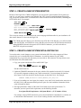
STEP 4 - CREATE A NEW SYSTEM MONITOR
Because of the Eagle 250’s CMOS configuration, you can give the system monitor file any name you
want. So, you can create a monitor to use after the AM-138-10 board is installed without affecting the
way your system performs now. Use MONGEN to create a monitor called AM138.MON, containing the
SCZ138 disk driver. For example:
LOG SYS: ENTER
MONGEN ENTER
Input monitor name: AMOS.MON ENTER
New disk driver: SCZ138.DVR ENTER
New language definition table name: ENGLSH
New monitor name: AM138.MON ENTER
SAVE AM138.MON
ENTER
ENTER
This is only an example; be sure to choose the correct language definition table for your installation. All
other entries shown are correct for the Eagle 250.
The CMOS menu also allows you to boot from any SCSI disk. If the disk drive you will boot from
is not at SCSI ID 0, use FIXLOG to create a disk driver for the correct SCSI ID and use that driver
during MONGEN instead of the generic SCZ138.DVR. Otherwise, you will not be able to
MONTST using the new monitor.
STEP 5 - CREATE A NEW SYSTEM INITIALIZATION FILE
You need to make several changes to your system initialization (INI) file so the computer will boot
correctly after you’ve installed the Eagle 250 hardware. As with the monitor file, the CMOS
configuration lets you give this file any name you want, with an .INI extension. The steps below create
an initialization file called AM138.INI.
1. Copy your system initialization file to AM138.INI. Type:
LOG SYS: ENTER
COPY AM138.INI=AMOS32.INI
ENTER
Edit the AM138.INI file.
2. Update the TRMDEF statements for the ports which will be attached to the AM-138-10 board.
It’s especially important to change port 0 (the boot terminal). You must change the interface
driver name to A31810, the driver used by the ports on the AM-138-10. For example:
TRMDEF TRMN,A31810=0:19200,AM62A,100,100,100
3. If you will be adding new serial ports (for example, a new AM-318-10 board) at the same time as
the AM-138-10, add statements defining the new ports. See the installation instructions for the
serial I/O board for details.
4. The high-performance features of the AM-138-10 board require more queue blocks. To
determine your new queue block requirement, use the following formula:
New Queue Block Requirement = Old Queue Blocks + (13 X Number of Jobs)
For example, if the QUEUE statement in your system initialization command file is currently set
to 200 and the JOBS statement is set to 50, the resulting formula would look like this:
Eagle 250 Upgrade Instructions, Rev. A00
Page 20
Chapter Five
New Queue Block Requirement = 200 + (13 x 50)
This example results in a setting of 850 queue blocks. However, we strongly recommend that you
use a minimum a 2,500 queue blocks, even if the formula results in a lower number.
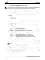
5. Since you will be booting from a SCSI disk drive connected to the AM-138-10 board, you need
to define the SCSI dispatcher for the Eagle 250 (described in Chapter 3) in the system
initialization command file. Add this command to the INI file after the JOBALC statements, but
before the first DEVTBL statement:
SCZDSP SCZ138.SYS
For example:
:T
JOBS 1
JOBALC
;
TRMDEF
VER
SCZDSP
;
DEVTBL
JOB1
TERM1,AM318=0:19200,AM62A,100,100,100,EDITOR=15
SCZ138.SYS/ET
DSK
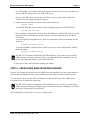
The SCZ138 dispatcher supports several option switches, as shown in the following table:
Switch
Description
/ET
Enable tolerant active negation
/EW
/EW:{id#}
Enable Wide SCSI negotiation for all devices
Enable Wide SCSI negotiation for SCSI device ID#
/NQ
/NQ:{id#}
Disable Command Queuing for all devices
Disable Command Queuing for SCSI device ID#
/NS
/NS:{id#}
Disable Synchronous Negotiation for all devices
Disable Synchronous Negotiation for SCSI device ID#
/NP
Disable Parity Checking (Parity still generated) on all devices
Table 5-1: Dispatcher Switch Table
We recommend that all Eagle 250s use the /ET switch (as shown above) to enable tolerant active
negation. Using active negation improves bus integrity when using synchronous data transfers.
Never attach a device to or remove a device from the SCSI bus while system power is
on. This is never a good idea, but active negation makes it even more likely that doing so
will damage the device, the SCSI controller, or both.
The most common of the other switches is /EW, to enable Wide SCSI operation when using the
optional Wide SCSI bus. If you have both Wide and narrow SCSI devices attached to the Wide
bus, enable Wide SCSI operation only for the Wide devices. For example, if you have a Wide
SCSI disk drive at SCSI ID 0 of the Wide bus, and narrow devices at other IDs, enter this
statement to enable Wide SCSI operation for just that drive:
SCZDSP SCZ138/ET/EW:0
Eagle 250 Upgrade Instructions, Rev. A00
Beginning an Eagle 250 Upgrade
Page 21
Use /EW without a device ID (to enable Wide operation for the entire bus) only if all devices on
the bus, both disk and tape drives, are Wide SCSI devices.
Do not use the /EW switch with the narrow SCSI bus, even if you have Wide SCSI devices
attached to the bus using the appropriate adapters.
6. Add or modify the DEVTBL statement for the parallel printer port:
DEVTBL /EGP0
To load EGP.DVR into system memory, add the following statement to the SYSTEM area:
SYSTEM DVR:EGP.DVR
7. If the computer is connected to a network, in the SYSTEM area of AM138.INI, add a line to load
the network driver for the Ethernet interface. (Remove any line loading the driver for the old
CPU board.)
To use the AlphaTCP compatible driver, which we recommend in almost all situations, use this
statement:
SYSTEM DVR:AM138.LDV/N
To use the AlphaNET compatible driver, which is necessary in certain configurations, add this
statement instead:
SYSTEM DVR:AM138.NDV/N
The AM-138-10 supports write buffering for SCSI disk drives. If you want to use this feature,
which can improve system performance, please read Appendix B before continuing. You may
need to make additional changes to your initialization file.
8. Save and exit from AM138.INI after making your changes.
STEP 6 - CREATE NEW SUBSYSTEM DISK DRIVERS
In step 4, you created a new disk driver for the DSK device and embedded it in a new system monitor. If
you have any non-DSK disk devices (subsystem disks), you also need to create new drivers for them.
To create the new drivers, use the FIXLOG command. See the FIXLOG sheet in the AMOS System
Commands Reference Manual for instructions.
The AM-138-10 supports read-ahead for SCSI hard disk drives. If you want to use this feature,
which can improve system performance, please read Appendix B before continuing. It will affect
the choices you make while using FIXLOG.
After creating the new disk drivers, be sure to save them to disk.
Eagle 250 Upgrade Instructions, Rev. A00
Page 22
Chapter Five
STEP 7 - NETWORK CONFIGURATION
In step 5, you changed a SYSTEM statement in the AM138.INI file to load the correct network interface
driver for the Eagle 250 Ethernet port you will be using. You must make the same change to the
AlphaTCP configuration file, CONFIG. To do this:
1. Log to TCP:.
2. Edit the CONFIG. File.
3. Change the IFCONFIG statement to AM138.LDV.
4. Save the file.
If the Eagle 250 won’t be using AlphaTCP, you can skip this step.
STEP 8 - PROTECT YOUR DATA AGAIN
Now that you’ve installed a new operating system, you should make a complete backup of DSK0:, and
create a new warm boot tape and/or bootable floppy disk. That way, in the unlikely event that you do
have to warm boot and restore your disk drive, you won’t have to repeat the installation of the new
operating system.
If you have an available logical disk device, you can copy DSK0: to it rather than making a
backup tape.
STEP 9 - INSTALL THE EAGLE 250 HARDWARE
The hardware installation procedure differs depending on the type of system you are upgrading from. For
specific installation instructions, please turn to the correct chapter for your upgrade:
• Eagle 100 — Chapter 6
• Eagle 200 or 300 — Chapter 7
Eagle 250 Upgrade Instructions, Rev. A00
Chapter 6 - Eagle 100 Upgrade
Hardware Installation
In this upgrade the AM-138-10 replaces the AM-137 CPU board. This upgrade procedure involves
removing the old CPU and rear panel and installing the AM-138-10 and a new rear panel. The following
instructions walk you through this process.
PREPARING FOR THE UPGRADE
Before starting the hardware upgrade, make sure you have completed all of the steps in Chapter 5,
"Beginning an Eagle 250 Upgrade." Do not begin the hardware installation until you've performed all of
the necessary preliminary processes.
While your computer's hardware is exposed and the AC power cord is unplugged, the components
are vulnerable to damage caused by static discharge. Your body and clothing are capable of
storing an electrical charge that can damage or destroy unprotected electronic components. Before
you handle any computer hardware, make certain your work area is properly protected against
static discharge. There are a number of commercially available static protection devices, like the
wrist strap shown in Chapter 3, designed specifically to protect your equipment from harmful
static discharge.
REMOVING THE CHASSIS COVER
1. Power down your computer and unplug the power cord.
2. Label and unplug all external cables.
3. At the rear of the computer, remove the four screws that attach the top cover to the chassis.
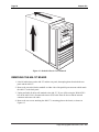
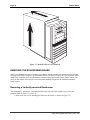
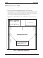
4. Slide the top cover back and lift the rear edge up (as indicated by the arrows on Figure 6-1).
Remove the cover and place it out of the way.
The pictures in this chapter show the chassis used for most Eagle computers. Your chassis may
look slightly different, but the installation procedure is essentially the same.
Eagle 250 Upgrade Instructions, Rev. A00
Page 24
Chapter Six
Figure 6-1: Deskside Chassis Cover Removal
REMOVING THE AM-137 BOARD
1. Label all cables between the AM-137 and the rear panel, then unplug them from both the rear
panel and the AM-137.
2. Remove the two male-female standoffs on either side of the parallel port connector which attach
the AM-137 to the back panel.
3. Unplug and label all cables still attached to the AM-137. If you will be using the Wide SCSI-2
bus on the AM-138-10, disconnect the narrow SCSI cable from all devices and the external
connector and remove the cable.
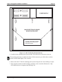
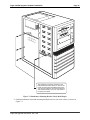
4. Remove the two screws attaching the AM-137’s mounting plate to the chassis, as shown in
Figure 6-2.
Eagle 250 Upgrade Instructions, Rev. A00
Eagle 100 Upgrade: Hardware Installation
Page 25
1
POWER SUPPLY
2
3
4
5
MAIN ELECTRONICS BOARD
MOUNTING BRACKET
6
To remove the board mounting
assembly, you must remove
these two screws.
Figure 6-2: AM-137 Mounting Bracket Removal
5. Carefully lift the mounting plate up and forward, toward the front of the chassis, then out.
The mounting plate helps to stabilize the chassis. With it removed, you will be able to rock the
chassis back and forth slightly. This is normal.
6. Remove the AM-137 from the mounting plate by unscrewing the nine screws holding it in place.
7. If the computer contains an AM-219 floppy controller, remove it and the diskette drive. Only
SCSI diskette drives are supported with the Eagle 250.
Eagle 250 Upgrade Instructions, Rev. A00
Page 26
Chapter Six
PREPARING THE AM-138-10 BOARD
1. Use eight of the mounting screws you just removed to attach the AM-138-10 to the mounting
plate.
2. If you haven’t yet, check the jumpers on the AM-138-10 board to make sure they are set
correctly. Refer to the table in Chapter 4.
3. Install one or two memory SIMMs at J10 (and J11), following the instructions in Chapter 3.
4. If you haven’t already done so, remove the SSD from your old CPU board (see page 16) and
carefully install it into the AM-138-10 board at U34 (see Figure 4-1).
5. If you are going to install the AM-138-10 board into a “new style chassis”, as described on page
1, install the small rear sub-panel (DWF-20765-10), included in your upgrade kit, to the 9-pin
and 25-pin connectors at the rear edge of the AM-138-10 board using the male / female standoffs
from the old rear panel yet to be removed.
INSTALLING THE NEW REAR PANEL AND AM-138-10 (OLD STYLE
CHASSIS)
If you have the new style chassis, skip ahead to the next section.
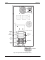
1. Remove the five screws attaching the rear panel to the chassis, as shown in Figure 6-3.
2. Attach the new Eagle 250 rear panel to the back of the chassis using the five screws you just
removed. Leave the screws loose for now.
3. Reinstall the CPU mounting plate, which now has the AM-138-10 attached. First slide the
connector end of the AM-138-10 into place in the rear panel. Then, move the other end into the
proper orientation and press down over the small locating bumps in the chassis bottom. You may
have to rock the chassis top slightly forward or back to lock the locating bumps in place, with the
mounting plate flush against the chassis bottom. Once the plate is placed properly, install its two
mounting screws.
4. Attach the AM-138-10 to the back panel using the provided male/female standoffs at the UPS
status port and the parallel port.
5. From the outside of the back panel, install the adhesive backed rectangular cover plate contained
in the upgrade kit over the 15-pin connector hole in the new rear panel next to the Parallel 0
connector.
6. Tighten the five screws attaching the rear panel to the back of the chassis.
7. Install cover plates over any connector mounting holes that will not be used to mount connectors.
The appropriate filler plates should either be obtained from the old rear panel or be provided in
your upgrade kit.
Eagle 250 Upgrade Instructions, Rev. A00
Eagle 100 Upgrade: Hardware Installation
Page 27
110
REMOVE THE TWO SCREWS
HOLDING THE SCSI CONNECTOR
TO THE REAR PANEL
MAIN
ALT
BOOT
H1
SCSI
H2
ETHERNET
PARALLEL 0
PARALLEL 1
G1
G2
F1
F2
E1
E2
D1
D2
C1
C2
B1
B2
A1
A2
REMOVE THESE
FIVE REAR PANEL
SCREWS
Figure 6-3: Removing the Old Rear Panel
Eagle 250 Upgrade Instructions, Rev. A00
Page 28
Chapter Six
INSTALLING THE NEW REAR PANEL AND AM-138-10 (NEW STYLE
CHASSIS)
If you have the old style chassis, you should have already performed this function in the previous section.
Skip ahead to the next section.
You will be removing the entire rear panel assembly in this section and replacing it with the new panel
contained in your upgrade kit.
1. Carefully position the computer chassis on its side to facilitate the rear panel removal.
2. Remove the four screws attaching the power supply to the rear panel and carefully lower the
power supply to rest on the work surface. You’ll be reinstalling it to the new rear panel in the
next few steps.
3. Remove any other connectors already attached to the rear panel. You will need to re-install these
once the new rear panel is assembled to the chassis.
4. Remove the three screws and nuts attaching the rear panel to the chassis bottom.
5. Remove the three screws and nuts attaching the rear panel to the chassis top. This should allow
you to completely remove the old rear panel.
6. Install the new rear panel to the chassis using the same six screws and nuts you just removed in
steps 3 and 4. Make sure the rear panel is oriented so that the power supply mounts toward the
top of the chassis when it is reoriented to its normal operating position. Figure 6-5 shows the
correct orientation for the new style chassis.
7. Re-attach the power supply to the new rear panel using the four screws removed in step 2 above.
8. Reinstall the rear panel connectors, removed in step 3, to the new rear panel. Figure 6-5 shows
the position of the standard I/O connectors.
9. Reinstall the CPU mounting plate, which now has the AM-138-10 and rear sub-panel attached.
First slide the connector end of the AM-138-10 into place in the rear panel. Then, move the other
end into the proper orientation and press down over the small locating bumps in the chassis
bottom. You may have to rock the chassis top slightly forward or back to lock the locating
bumps in place, with the mounting plate flush against the chassis bottom. Once the plate is
placed properly, install its two mounting screws.
10. Attach the AM-138-10 rear sub-panel to the back panel using three screws.
11. From the outside of the back panel, install the adhesive backed rectangular cover plate contained
in the upgrade kit over the 15-pin connector hole in the new rear sub-panel next to the Parallel 0
connector.
12. Install cover plates over any connector mounting holes that will not be used to mount connectors.
The appropriate filler plates should either be obtained from the old rear panel or be provided in
your upgrade kit.
Eagle 250 Upgrade Instructions, Rev. A00
Eagle 100 Upgrade: Hardware Installation
Page 29
HOOKING UP THE AM-138-10
1. Attach two 6-pin cables from the power supply at P3 and P4 on the AM-138-10.
2. Attach the SCSI cable to the AM-138-10:
• If you’re using the narrow SCSI bus, plug the existing SCSI cable into P7. Install the
active SCSI terminator supplied in your upgrade kit into the SCSI external connector at the
rear panel. See Appendix A for further SCSI terminator details.
• For the Wide SCSI-2 bus, detach and remove the narrow SCSI cable if you haven’t already
done so. Plug the new wide cable into J13. Route it to each SCSI device, and then to the
external cutout on the back panel. Use the wide SCSI-to-50-pin adapter (PRA-00259-50)
to mount the external 68-pin connector. Attach the connector to the adapter using the
provided standoffs. If you have narrow SCSI devices, you must use a 50-pin to 68-pin
adapter (PDB-00440-91) to attach each to the wide SCSI cable. Install the active SCSI
terminator supplied in your upgrade kit into the SCSI external connector at the rear panel.
See Appendix A for further SCSI terminator details.
3. Attach I/O cables to any serial I/O boards you’ll be installing. You must attach the cables to the
boards before installing the boards in the AM-138-10.
CAUTION: Take care when removing or adding any I/O SIMM board. Do not force the
board into or out of the SIMM connector. These connectors are fragile and may break if
not handled properly. Do not remove or attach an I/O cable while the I/O board is
plugged into the SIMM connector.
4. Install any serial I/O boards (AM-314, AM-318-00, -02 or -10) into the slots at J7, J8, and J9. If
you are mixing I/O boards, we generally recommend you begin with an 8-port AM-318-xx
boards in J7, and place any AM-314 boards in the last used slots. However, you can place the
AM-314 in any slot for compatibility with your previous configuration. See Chapter 3 of the
Eagle 250 Installation and Technical Manual for more serial I/O configuration information.
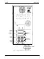
5. If you purchased the optional AM-90 Lightning boards for the eight on-board serial I/O ports,
install them into each of the two bottom rear panel I/O slots (see Figure 6-4). Attach the cable
from the board for ports 0-3 at P1 on the AM-138-10; attach the cable from ports 4-7 at P2.
If you are using DB-9 connectors for the eight on-board serial ports, use the same cables you
used to connect the on-board ports on the AM-137 to the back panel. Use the dual DB-9
connector adapter plates to mount the DB-9 connectors to the back panel. If you choose this
option, you’ll need the bottom four back panel slots, instead of two, for the eight on-board ports.
6. Install cabling from any other serial I/O boards to the back panel, following the installation
instructions for the I/O board. If you’re using AM-90 cards for the back panel connections
(which we recommend), insert the bottom AM-90s first and work your way up the back panel.
Make sure pin-1 orientation is correct for all cable connections.
7. If you have a brace for the serial I/O boards (DWB-20791-00 or -01), install it following the
instructions in PDI-20791-00.
Eagle 250 Upgrade Instructions, Rev. A00
Page 30
Chapter Six
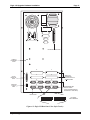
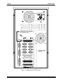
115
EXTERNAL SCSI PORT
10-BaseT
ETHERNET
PORT
INSTALL
COVER PLATE
HERE
SERIAL I/O
EXPANSION
SLOTS
25-PIN
PARALLEL
PORT
8 STANDARD
SERIAL PORTS
9-PIN UPS
STATUS
PORT
BOOT PORT
OPTIONAL
AM-90 BOARDS
Figure 6-4: Eagle 250 Rear Panel (Old Style Chassis)
Eagle 250 Upgrade Instructions, Rev. A00
Eagle 100 Upgrade: Hardware Installation
Page 31
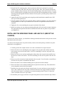
0
SCSI
115
EXTERNAL SCSI PORT
10-BaseT
ETHERNET
PORT
25-PIN
PARALLEL
PORT
9-PIN UPS
STATUS
PORT
6
7
4
5
2
3
0
1
SERIAL I/O
EXPANSION
SLOTS FOR RJ-45
CONNECTORS
8 STANDARD DB9
SERIAL PORTS
(RJ-45 CONFIGURATION
OPTIONALLY AVAILABLE)
BOOT PORT
OPTIONAL
AM-90 BOARDS
Figure 6-5: Eagle 250 Rear Panel (New Style Chassis)
Eagle 250 Upgrade Instructions, Rev. A00
Page 32
Chapter Six
8. Attach the front panel display cable. If it’s a 26-pin connector, use P9; a 20-pin connector plugs
in at P10.
If you use the 20-pin connector, you should also have four wire pairs which were connected to
the front panel from the AM-137. Attach these to the P8 connector on the AM-138-10, as
follows:
Board Label
Run
Wires
Yellow/White
Disk
Red/White
Power
Reset
Green/White
Green/Black
Purpose/Notes
Run light; white wire goes toward
edge of board.*
Disk activity light; white wire toward
edge.*
Power light; white wire toward edge*
Reset switch
*: If the light does not work in this orientation, reverse the wires.
FINISHING UP
The hardware portion of the upgrade is complete. Continue with Chapter 8 to test and boot the new Eagle
250. Perform these procedures before attaching the computer's cover, in case you need to make some
adjustments.
Once your system completes the testing procedures successfully, shut it off again and reattach the top
cover.
Eagle 250 Upgrade Instructions, Rev. A00
Chapter 7 - Eagle 200/300 Upgrade
Hardware Installation
In this upgrade the AM-138-10 replaces the AM-172 Roadrunner board and the AM-319 system board.
This upgrade procedure involves removing these two boards and the rear panel and installing the AM138-10 and a new rear panel. The following instructions walk you through this process.
PREPARING FOR THE UPGRADE
Before starting the hardware upgrade, make sure you have completed all of the steps in Chapter 5,
"Beginning an Eagle 250 Upgrade." Do not begin the hardware installation until you've performed all of
the necessary preliminary processes.
While your computer's hardware is exposed and the AC power cord is unplugged, the components
are vulnerable to damage caused by static discharge. Your body and clothing are capable of
storing an electrical charge that can damage or destroy unprotected electronic components. Before
you handle any computer hardware, make certain your work area is properly protected against
static discharge. There are a number of commercially available static protection devices, like the
wrist strap shown in Chapter 3, designed specifically to protect your equipment from harmful
static discharge.
REMOVING THE CHASSIS COVER
1. Power down your computer and unplug the power cord.
2. Label and unplug all external cables.
3. At the rear of the computer, remove the four screws that attach the top cover to the chassis.
4. Slide the top cover back and lift the rear edge up (as indicated by the arrows on Figure 7-1).
Remove the cover and place it out of the way.
The pictures in this chapter show the chassis used for most Eagle computers. Your chassis may
look slightly different, but the installation procedure is essentially the same.
Eagle 250 Upgrade Instructions, Rev. A00
Page 34
Chapter Seven
Figure 7-1: Deskside Chassis Cover Removal
REMOVING THE ROADRUNNER BOARD
Where your Roadrunner board is located in your chassis depends on when you purchased your computer.
On early-model Eagle computers, the Roadrunner board is mounted vertically on a special bracket. Later
model Eagle computers have their Roadrunner boards mounted horizontally on the chassis bottom. The
screen on the bottom of the chassis has four threaded standoffs designed to the hold the Roadrunner
board in place.
Removing a Vertically-mounted Roadrunner
The Roadrunner is attached to a mounting bracket on the left side of the computer (as you face the
computer from the front). To remove it:
1. Remove the four screws attaching the bracket to the chassis, as shown in Figure 7-2.
Eagle 250 Upgrade Instructions, Rev. A00
Eagle 300/500 Upgrade: Hardware Installation
Page 35
DW
F-2
0
DW or754-0
0
F-2
075
4-0
1
The Roadrunner board is mounted on the
DWF-20754-00 bracket shown.To remove the
board, remove these four Phillips-head screws.
You can then fold down the mounting bracket
and board assembly onto your work surface
to unplug the cables.
Figure 7-2: Roadrunner Mounting Bracket, Early-Model Eagles
2. Fold the Roadrunner board and mounting bracket down onto your work surface, as shown in
Figure 7-3.
Eagle 250 Upgrade Instructions, Rev. A00
Page 36
Chapter Seven
ROADRUNNER 030
BOARD
Before removing the Roadrunner board, unplug
the two cables from the X-Bus connectors, the
SCSI cable, and the 4-pin power cable. Then,
remove the entire Roadrunner board/mounting
bracket assembly.
Figure 7-3: Roadrunner Removal, Early-Model Eagles
3. Unplug all cables from the Roadrunner board, including the SCSI cable, power cable, X-bus
cables, etc.
4. Lift out the entire Roadrunner/bracket assembly.
Eagle 250 Upgrade Instructions, Rev. A00
Eagle 300/500 Upgrade: Hardware Installation
Page 37
Removing a Horizontally-mounted Roadrunner
The Roadrunner is attached to a screen on the bottom of the chassis using four male/female standoffs and
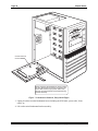
four 6-32 Phillips-head screws. To remove it:
1. Unplug all cables from the Roadrunner board, including the SCSI cable, power cable, X-bus
cables, etc.
2. Unscrew the four Phillips-head screws holding the Roadrunner to the standoffs and lift the board
out.
3. Unscrew the standoffs from the screen on the chassis bottom. They aren’t needed in the Eagle
250.
6-32 PHILLIPS-HEAD
SCREW
In this configuration, the Roadrunner board is
mounted on top of four standoffs which are
attached directly to the screen on the bottom
of the chassis.
Figure 7-4: Roadrunner Removal, Late-model Eagles
Eagle 250 Upgrade Instructions, Rev. A00
Page 38
Chapter Seven
REMOVING THE AM-319 BOARD
1. Label all cables between the AM-319 and the rear panel, then unplug them from both the rear
panel and the AM-319.
2. Remove the two male-female standoffs attaching the AM-319 to the back panel.
3. Unplug all cables still attached to the AM-319 (the X-bus cables, power cables, SCSI cable, and
front panel display cable). Label the power and display cables, as they’ll be used in the Eagle
250. If you will be using the Wide SCSI-2 bus on the AM-138-10, disconnect the narrow SCSI
cable from all devices and the external connector and remove the cable.
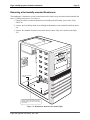
4. Remove the two screws attaching the AM-319’s mounting plate to the chassis, as shown in
Figure 7-5.
1
POWER SUPPLY
2
3
4
5
MAIN ELECTRONICS BOARD
MOUNTING BRACKET
6
To remove the board mounting
assembly, you must remove
these two screws.
Figure 7-5: AM-319 Mounting Bracket Removal
5. Carefully lift the mounting plate up and forward, toward the front of the chassis, then out.
Eagle 250 Upgrade Instructions, Rev. A00
Eagle 300/500 Upgrade: Hardware Installation
Page 39
The mounting plate helps to stabilize the chassis. With it removed, You will be able to rock
the chassis back and forth slightly. This is normal.
6. Remove the AM-319 from the mounting plate by unscrewing the nine screws holding it in place.
7. If the computer contains an AM-219 floppy controller, remove it and the diskette drive. Only
SCSI diskette drives are supported with the Eagle 250.
PREPARING THE AM-138-10 BOARD
1. Use eight of the mounting screws you just removed to attach the AM-138-10 to the mounting
plate.
2. If you haven’t yet, check the jumpers on the AM-138-10 board to make sure they are set
correctly. Refer to the table in Chapter 4.
3. Install one or two memory SIMMs at J10 (and J11), following the instructions in Chapter 3.
4. If you haven’t already done so, remove the SSD from your old CPU board (see page 16) and
carefully install it into the AM-138-10 board at U34 (see Figure 4-1).
5. If you are going to install the AM-138-10 board into a “new style chassis”, as described on page
1, install the small rear sub-panel (DWF-20765-10), included in your upgrade kit, to the 9-pin
and 25-pin connectors at the rear edge of the AM-138-10 board using the male / female standoffs
from the old rear panel yet to be removed.
INSTALLING THE NEW REAR PANEL AND AM-138-10 (OLD STYLE
CHASSIS)
If you have the new style chassis, skip ahead to the next section.
1. Remove the four screws attaching the fan to the back panel and the back of the chassis. Save the
screws.
2. Remove the five screws attaching the rear panel to the chassis, as shown in Figure 7-6. Save
these screws, also.
3. The new rear panel is smaller, so the fan attaches directly to the back of the chassis. Use the same
four screws to reattach it in the same position it previously occupied.
4. Attach the new Eagle 250 rear panel to the back of the chassis using the five screws you just
removed. Leave the screws loose for now.
Eagle 250 Upgrade Instructions, Rev. A00
Page 40
Chapter Seven
110
REMOVE THE TWO SCREWS
HOLDING THE SCSI CONNECTOR
TO THE REAR PANEL
MAIN
ALT
BOOT
H1
SCSI
H2
ETHERNET
PARALLEL 0
PARALLEL 1
G1
G2
F1
F2
E1
E2
D1
D2
C1
C2
B1
B2
A1
A2
REMOVE THESE
FIVE REAR PANEL
SCREWS
Figure 7-6: Removing the Old Rear Panel
Eagle 250 Upgrade Instructions, Rev. A00
Eagle 300/500 Upgrade: Hardware Installation
Page 41
5. Reinstall the CPU mounting plate, which now has the AM-138-10 attached. First slide the
connector end of the AM-138-10 into place in the rear panel. Then, move the other end into the
proper orientation and press down over the small locating bumps in the chassis bottom. You may
have to rock the chassis top slightly forward or back to lock the locating bumps in place, with the
mounting plate flush against the chassis bottom. Once the plate is placed properly, install its two
mounting screws.
6. Attach the AM-138-10 to the back panel using the provided male/female standoffs at the UPS
status port and the parallel port.
7. From the outside of the back panel, install the adhesive backed rectangular cover plate contained
in the upgrade kit over the 15-pin connector hole in the new rear panel next to the Parallel 0
connector.
8. Tighten the five screws attaching the rear panel to the back of the chassis.
9. Install cover plates over any connector mounting holes that will not be used to mount connectors.
The appropriate filler plates should either be obtained from the old rear panel or be provided in
your upgrade kit.
INSTALLING THE NEW REAR PANEL AND AM-138-10 (NEW STYLE
CHASSIS)
If you have the old style chassis, you should have already performed this function in the previous section.
Skip ahead to the next section.
You will be removing the entire rear panel assembly in this section and replacing it with the new panel
contained in your upgrade kit.
1. Carefully position the computer chassis on its side to facilitate the rear panel removal.
2. Remove the four screws attaching the power supply to the rear panel and carefully lower the
power supply to rest on the work surface. You’ll be reinstalling it to the new rear panel in the
next few steps.
3. Remove the four screws and nuts attaching the exhaust fan to the rear panel and carefully lower
the fan to rest on the work surface. You’ll be reinstalling it to the new rear panel in the next few
steps.
4. Remove any other connectors already attached to the rear panel. You will need to re-install these
once the new rear panel is assembled to the chassis.
5. Remove the three screws and nuts attaching the rear panel to the chassis bottom.
6. Remove the three screws and nuts attaching the rear panel to the chassis top. This should allow
you to completely remove the old rear panel.
7. Install the new rear panel to the chassis using the same six screws and nuts you just removed in
steps 3 and 4. Make sure the rear panel is oriented so that the power supply mounts toward the
top of the chassis when it is reoriented to its normal operating position. Figure 6-5 shows the
correct orientation for the new style chassis.
8. Re-attach the power supply to the new rear panel using the four screws removed in step 2 above.
Eagle 250 Upgrade Instructions, Rev. A00
Page 42
Chapter Seven
9. Re-attach the fan to the new rear panel using the four screws and nuts removed in step 3 above.
Make sure it is oriented to exhaust air out of the chassis, in the same orientation it was previously
installed.
10. Reinstall the rear panel connectors, removed in step 3, to the new rear panel. Figure 6-5 shows
the position of the standard I/O connectors.
11. Reinstall the CPU mounting plate, which now has the AM-138-10 and rear sub-panel attached.
First slide the connector end of the AM-138-10 into place in the rear panel. Then, move the other
end into the proper orientation and press down over the small locating bumps in the chassis
bottom. You may have to rock the chassis top slightly forward or back to lock the locating
bumps in place, with the mounting plate flush against the chassis bottom. Once the plate is
placed properly, install its two mounting screws.
12. Attach the AM-138-10 rear sub-panel to the back panel using three screws.
13. From the outside of the back panel, install the adhesive backed rectangular cover plate contained
in the upgrade kit over the 15-pin connector hole in the new rear sub-panel next to the Parallel 0
connector.
14. Install cover plates over any connector mounting holes that will not be used to mount connectors.
The appropriate filler plates should either be obtained from the old rear panel or be provided in
your upgrade kit.
HOOKING UP THE AM-138-10
1. Attach two 6-pin cables from the power supply at P3 and P4 on the AM-138-10.
2. Attach the SCSI cable to the AM-138-10:
• If you’re using the narrow SCSI bus, plug the existing SCSI cable into P7. Install the
active SCSI terminator supplied in your upgrade kit into the SCSI external connector at the
rear panel. See Appendix A for further SCSI terminator details.
• For the Wide SCSI-2 bus, detach and remove the narrow SCSI cable if you haven’t already
done so. Plug the new wide cable into J13. Route it to each SCSI device, and then to the
external cutout on the back panel. Use the wide SCSI-to-50-pin adapter (PRA-00259-50)
to mount the external 68-pin connector. Attach the connector to the adapter using the
provided standoffs. If you have narrow SCSI devices, you must use a 50-pin to 68-pin
adapter (PDB-00440-91) to attach each to the wide SCSI cable. Install the active SCSI
terminator supplied in your upgrade kit into the SCSI external connector at the rear panel.
See Appendix A for further SCSI terminator details.
3. Attach I/O cables to any serial I/O boards you’ll be installing. You must attach the cables to the
boards before installing the boards in the AM-138-10.
CAUTION: Take care when removing or adding any I/O SIMM board. Do not force the
board into or out of the SIMM connector. These connectors are fragile and may break if
not handled properly. Do not remove or attach an I/O cable while the I/O board is
plugged into the SIMM connector.
4. Install any serial I/O boards (AM-314, AM-318-00, -02 or -10) into the slots at J7, J8, and J9. If
you are mixing I/O boards, we generally recommend you begin with an 8-port AM-318-xx
boards in J7, and place any AM-314 boards in the last used slots. However, you can place the
Eagle 250 Upgrade Instructions, Rev. A00
Eagle 300/500 Upgrade: Hardware Installation
Page 43
AM-314 in any slot for compatibility with your previous configuration. See Chapter 3 of the
Eagle 250 Installation and Technical Manual for more serial I/O configuration information.
5. If you purchased the optional AM-90 Lightning boards for the eight on-board serial I/O ports,
install them into each of the two bottom rear panel I/O slots (see Figure 7-7). Attach the cable
from the board for ports 0-3 at P1 on the AM-138-10; attach the cable from ports 4-7 at P2.
If you are using DB-9 connectors for the eight on-board serial ports, use the same cables you
used to connect the initial eight serial I/O ports on-your Eagle 200 or 300 to route the on-board
serial ports to the back panel. Use the dual DB-9 connector adapter plates to mount the DB-9
connectors to the back panel. If you choose this option, you’ll need the bottom four back panel
slots, instead of two, for the eight on-board ports.
6. Install cabling from any other serial I/O boards to the back panel, following the installation
instructions for the I/O board. If you’re using AM-90 cards for the back panel connections
(which we recommend), insert the bottom AM-90s first and work your way up the back panel.
Make sure pin-1 orientation is correct for all cable connections.
7. If you have a brace for the serial I/O boards (DWB-20791-00 or -01), install it following the
instructions in PDI-20791-00.
8. Attach the front panel display cable. If it’s a 26-pin connector, use P9; a 20-pin connector plugs
in at P10.
If you use the 20-pin connector, you should also have four wire pairs which were connected to
the front panel from the AM-319. Attach these to the P8 connector on the AM-138-10, as
follows:
Board Label
Run
Wires
Yellow/White
Disk
Red/White
Power
Reset
Green/White
Green/Black
Purpose/Notes
Run light; white wire goes toward
edge of board.*
Disk activity light; white wire toward
edge.*
Power light; white wire toward edge*
Reset switch
*: If the light does not work in this orientation, reverse the wires.
Eagle 250 Upgrade Instructions, Rev. A00
Page 44
Chapter Seven
115
EXTERNAL SCSI PORT
10-BaseT
ETHERNET
PORT
INSTALL
COVER PLATE
HERE
SERIAL I/O
EXPANSION
SLOTS
25-PIN
PARALLEL
PORT
8 STANDARD
SERIAL PORTS
9-PIN UPS
STATUS
PORT
BOOT PORT
OPTIONAL
AM-90 BOARDS
Figure 7-7: Eagle 250 Rear Panel (Old Style Chassis)
Eagle 250 Upgrade Instructions, Rev. A00
Eagle 300/500 Upgrade: Hardware Installation
Page 45
0
SCSI
115
EXTERNAL SCSI PORT
10-BaseT
ETHERNET
PORT
25-PIN
PARALLEL
PORT
9-PIN UPS
STATUS
PORT
6
7
4
5
2
3
0
1
SERIAL I/O
EXPANSION
SLOTS FOR RJ-45
CONNECTORS
8 STANDARD DB9
SERIAL PORTS
(RJ-45 CONFIGURATION
OPTIONALLY AVAILABLE)
BOOT PORT
OPTIONAL
AM-90 BOARDS
Figure 7-8: Eagle 250 Rear Panel (New Style Chassis)
Eagle 250 Upgrade Instructions, Rev. A00
Page 46
Chapter Seven
FINISHING UP
The hardware portion of the upgrade is complete. Continue with Chapter 8 to test and boot the new Eagle
250. Perform these procedures before attaching the computer's cover, in case you need to make some
adjustments.
Once your system completes the testing procedures successfully, shut it off again and reattach the top
cover.
Eagle 250 Upgrade Instructions, Rev. A00
Chapter 8 - Testing the New
System
After you’ve installed the new hardware, you need to test the system to make sure it works properly in its
new configuration. To do so:
1. Run self-test.
2. If the system passes the self-test, access the CMOS Configuration menu to define your
configuration, then boot the computer. Make sure it boots correctly with your new configuration.
3. Rename your new system monitor and initialization files.
4. Back up the entire system and make a new warm boot tape.
The sections below give more information on each step.
RUNNING A SELF-TEST
Once you have completed the hardware installation, run the Self Test program to make sure each
subsystem is functional. The self test diagnostics are incorporated into the boot PROMs on the AM-13810. Refer to the System Self Test User's Guide, DSO-00157-00, for more information.
To begin the self-test procedure, hold the reset button and turn on the computer. When the front panel
displays "56", press SPACE several times on the boot terminal. The CPU will output the results of the selftest to that terminal.
If any problem arises, contact the Alpha Micro Technical Assistance Center.
SET YOUR CMOS CONFIGURATION AND BOOT
Once you have completed the self test, press the reset button and access the CMOS Configuration menu,
as described in the Eagle 250 Installation and Technical Manual. After setting the correct monitor and
initialization file names (AM138.MON and AM138.INI), save your configuration and the system will
reboot itself. As the computer boots, watch the boot terminal for error messages. After the computer
finishes booting, at the AMOS prompt, type:
SYSTAT
ENTER
Check the system status information displayed by the SYSTAT program and insure all disks are
accessible and all jobs are up and running—terminals, printers, task manager, network jobs, etc.
To check on the status of all jobs, we recommend that you type:
STAT
ENTER
Eagle 250 Upgrade Instructions, Rev. A00
Page 48
Chapter Six
RENAMING THE SYSTEM MONITOR AND INITIALIZATION FILES
Once the system has passed the self-test and you have made sure that all jobs are up and running:
1. Make archive copies of your previous monitor and initialization files. For example:
LOG SYS: ENTER
COPY OLDMON.MON=AMOS32.MON
COPY OLDINI.INI=AMOS32.INI
ENTER
ENTER
2. Rename the AM138.MON and AM138.INI files to AMOS32.MON and AMOS32.INI:
COPY AMOS32.MON=AM138.MON
COPY AMOS32.INI=AM138.INI
ENTER
ENTER
3. Access the CMOS Configuration menu and change its settings to reflect the new monitor and
initialization file names. CMOS Configuration is described in the Eagle 250 Installation and
Technical Manual.
BACK UP AND MAKE A NEW WARM BOOT TAPE
Now that you’ve finished the upgrade installation, you need to safeguard your data in the new
configuration. Use your normal backup procedure to make and verify a complete system backup, as
discussed in Chapter 5. Then, create and test a new warm boot tape (and/or bootable diskette) which
reflects the new system configuration.
If you do not back up your system and make a good warm boot tape, you risk losing your data and/or
having to repeat large portions of the upgrade procedure!
ADDITIONAL DOCUMENTATION
For additional hardware information, refer to the following:
•
•
•
•
•
•
System Self Test User's Guide, DSO-00156-00
Alpha Micro Installation and Planning Guide, DSO-00034-00
Eagle 250 User’s Manual, DSO-00221-00
Eagle 250 Installation and Technical Manual, DSO-00222-00
Eagle Service manual, DSO-00223-00
The installation instructions for any other hardware you are installing, such as serial I/O cards.
For additional software information, refer to the following:
•
•
•
•
AMOS System Operator's Guide, DSO-00001-00.
AMOS System Operator’s Guide to the System Initialization Command File, DSO-00002-00
AMOS System Commands Reference Manual, DSO-00043-00.
The Release Notes for your version of AMOS
Eagle 250 Upgrade Instructions, Rev. A00
Appendix A - SCSI Termination
SCSI TERMINATION USING EXTERNAL TERMINATOR
The preferred method of terminating the SCSI bus in an AMOS based computer is the installation of an
external terminator. In April 1993, the external SCSI bus terminator became standard on all AMOS
computers. Using an external terminator makes installing an add-on subsystem (like a portable CD-ROM
drive) easier, eliminating the need to remove terminators from a SCSI device located in the host
computer. In the Eagle 250, the external terminator must be an “active” terminator. Do not continue to
use the passive terminator from your earlier system after you upgrade to the Eagle 250.
The SCSI bus must be terminated at each end of the cable. The AM-138-10 terminates one end of the
bus. The other end must be terminated by an active external terminator. An active terminator for the
SCSI bus you ordered—either narrow (PRA-00222-21) or Wide (PRA-00222-20)—is included in your
Eagle 250 upgrade kit.
The AM-138-10 board is sensitive to incorrect SCSI bus termination. If you are using the
external terminator and one of the SCSI devices inside the computer also has its terminators
installed, you will experience problems.
To use the external terminator, make sure none of the SCSI peripherals inside the computer are
terminated. The termination power for the SCSI bus is provided by the AM-138-10 board.
An external narrow terminator is shown in Figure A-1:
NARROW SCSI TERMINATOR
BAIL LOCKS
I
S
SC
(PRA-00222-21)
EXTERNAL SCSI BUS
ACTIVE TERMINATOR
Figure A-1: Active External Terminator Installation
Eagle 250 Upgrade Instructions, Rev. A00
Page 50
Appendix A
Figure A-1 shows an extended active external narrow SCSI connector and bail locks for holding the
terminator in place. The terminator is installed by sliding it over the connector and then latching the bail
locks into the notches in the terminator.
ATTACHING EXTERNAL DEVICES
To attach an external SCSI device, you must remove the terminator from the external SCSI port.
However, you must make sure the SCSI bus is still terminated at both ends. To do so, install the external
active terminator in the unused SCSI I/O port of the external SCSI device.
Attaching an external narrow SCSI device, such as a CD-ROM drive, to a system using the Wide SCSI
bus is a special case. You must make sure all 16 lines of the Wide SCSI bus are properly terminated. To
do so:
1. Use an external wide to narrow SCSI cable which actively terminates the “high” nine lines of the
Wide SCSI bus. Alpha Micro offers this cable in both three foot and six foot lengths
(PDB-00440-80 and PDB-00440-81).
2. Plug the narrow active external terminator provided with your Roadrunner mounting kit
(PRA-00222-21) into the unused SCSI I/O port of the external device. This terminates the “low”
half of the SCSI bus.
Notice that, in this configuration, the Wide SCSI active external terminator (PRA-00222-20), which is
normally plugged into the external SCSI port, is not used.
TERMINATOR POWER
For information on how to configure terminator power, see the installation instructions for your tape
drive and/or the configuration document accompanying your disk drive. In almost all cases, all devices
should be configured to accept termination power from the SCSI bus. The host controller on the AM138-10 supplies termination power.
Eagle 250 Upgrade Instructions, Rev. A00
Appendix B - Read-ahead and
Write Buffering
The AM-138-10 board uses a programmable RISC DMA controller for SCSI bus communications and
for data transfer to and from the AM-138-10's SCSI bus. The ColdFire CPU is only involved with setup
before and cleanup after a SCSI command is sent to a devicethe rest of the command, including data
transfer, is handled by the RISC processor.
Having the RISC processor take care of these details allows both read-ahead and write buffering without
the need for a separate controller.
READ-AHEAD
The AM-138-10's SCSI disk driver, SCZ138.DVR, is able to perform read-ahead directly into the AMOS
(DCACHE) disk cache. When any program attempts to read a physical block from a disk, the SCZ138
driver will also read up to an additional seven sequential blocks from the disk drive and store these readahead blocks in the cache.
This read-ahead scheme works very well when jobs on the system are doing a large number of sequential
reads. For example, data base searches and programs like REDALL may execute much faster because the
data they require is already in memory and only has to be transferred from the cache into the user
partition.
Programs that do significant random disk access (such as RNDRED) tend to slow down with this readahead scheme. Most of the slowdown is caused by "thrashing" of the disk cache, where cache entries that
will be used again are removed from the cache due to the allocation requirements of the read-ahead
blocks (which typically are never used). The actual data transfer overhead is very little, as most SCSI
disk drives (especially fast SCSI-2 drives) have a track cache built into the drive allowing both the target
and read-ahead blocks to be transferred over the SCSI cable without delay.
Controlling Read-Ahead
For read-ahead to occur on the AM-138-10, both the AMOS disk cache (DCACHE.SYS) and the full
SCSI dispatcher (SCZ138.SYS) must be installed. The number of read-ahead blocks to be transferred
into cache on every physical disk read is contained in the disk driver. You can set this using the FIXLOG
program to generate a disk driver with the appropriate read-ahead blocking factor.
When you use FIXLOG to create a driver for the AM-138-10 board, you are asked to specify the number
of read-ahead blocks. For example, type:
Eagle 250 Upgrade Instructions, Rev. A00
Page 52
Appendix B
FIXLOG ENTER
FIXLOG.LIT Version x.x(xxx)
1. Change the number of logicals.
2. Create a sub-system driver.
Enter choice: 2
ENTER
Enter name of generic driver to be used: SCZ138 ENTER
Enter number of logical units per physical unit: 10
Enter SCSI id (0-15): 0 ENTER
Enter number of read-ahead blocks (0-7): 5 ENTER
Enter new driver name: DSK ENTER
New driver is now in memory.
ENTER
To save the driver you have created, type:
SAVE DSK.DVR
ENTER
If you wish to disable or change the number of read-ahead blocks, simply use FIXLOG to generate a new
disk driver. If the disk driver is for the DSK: device, don't forget to use MONGEN and embed the new
driver into the system monitor.
The generic AM-138 SCSI disk driver (SCZ138.DVR) is set up for seven read-ahead blocks.
WRITE BUFFERING
AMOS (and therefore every application written for AMOS) understands only 512-byte disk blocks.
Therefore, when a disk write request is made by a program, a single block transfer is made to the disk
drive. If the program then writes the next sequential block, the system must wait the latency time of the
drive (i.e., the time it takes the drive to complete one revolution) before the next block can be written.
Latency, even on fast SCSI-2 drives, is around 7ms.
Write buffering can speed up the write process. When write buffering is enabled, all writes to the SCSI
disk are first transferred into a buffer. If the write buffer becomes at least half full, or around three
quarters of a second passes with no reads, or if a preset "guaranteed flush" time-out occurs, the
SCZ138.DVR disk driver will begin scanning through the write buffer, finding blocks that need to be
written out to the drive. The algorithm used to flush blocks out to the drive is able to find up to eight
consecutive blocks and write them to the disk drive as a single write command, therefore dramatically
improving system performance.
Another benefit of write buffering is it tends to eliminate duplicate disk writes, such as bitmap updates
during operations such as copying files and tape restores, and prevents head thrashing when reading
through random access data files and writing a sequential file out to the disk (as most report generation
programs do).
Eagle 250 Upgrade Instructions, Rev. A00
Read-ahead and Write Buffering
Page 53
Potential Pitfalls
Obviously, there can be problems with write buffering, especially if the system either crashes or is
powered off while writes are pending in the write buffer. If that happens, all pending writes are lost.
Though this sounds like a major problem, it can also happen if write buffering is not enabled. However,
write buffering increases the number of writes at risk. The primary write buffering risks are an errant
software operation or a hardware failure that causes a system crash.
To help reduce the possibility of data loss, certain safeguards have been put in place. Writes are not
buffered indefinitely; they are performed whenever the device is not performing reads. Even if the drive
is busy with read requests, the buffer is still periodically flushed, based on a user definable "absolute
flush time." In addition, if you have a UPS installed and connected to the AM-138-10's UPS status port,
and you experience a power failure and the UPS status port senses a low battery condition, AMOS will
flush and disable the write buffer in preparation for a system shutdown. Also, the MONTST command
automatically flushes the write buffer.
Therefore, you must weigh the potential for data loss (which is always there) versus the dramatic
performance increase seen when using write buffering. If you are worried about the reliability of write
buffering, it may be worth keeping in mind that the AM-520 disk controller has always used write
buffering on a track-by-track basis (however, not quite as efficiently as the AM-138-10 write buffering
scheme). The SMARTDRV program that comes with MS-DOS does write buffering (you may have
noticed the "Waiting for system shutdown" message when rebooting a PC with CTRL-ALT-DELETE)
and UNIX-based computers have always done it.
Setting Up Write Buffering
To enable write buffering, you must be using the full SCSI dispatcher (SCZ138-10.SYS). Enable write
buffering by adding parameters to the SYSTEM statement used to load the SCSI disk driver into system
memory. Append "/N" followed by the buffer size and flush period enables write buffering for that
device. The syntax is:
SYSTEM DVR:dev/N buffer-size flush-period
The buffer-size is the size of the write buffer (you specify the size in Kilobytes). We advise a buffer size
of 100K to 200K.
The flush-period is the maximum number of seconds data may be left in the write buffer without being
written to the disk. For example, if you specify 30, you will know that after 30 seconds any pending
writes will be written to the disk. This is true even if the disk is constantly busy servicing reads.
For example:
SYSTEM DVR:DSK/N 200K 60
One SYSTEM command is required for each different SCSI disk driver present in the system. For
example, if you have two 1.2GB SCSI-2 drives named DSK0-36 and DSK37-73 and one 540MB SCSI-2
drive named SUB0-17, you need one SYSTEM command for the DSK device (although it's really two
physical drives) and one SYSTEM command for the SUB device.
Eagle 250 Upgrade Instructions, Rev. A00
Page 54
Appendix B
When specifying write buffering for a device, two files are placed into system memory: .DVR
(loaded from disk) and .WRC (directly created in system memory), which are the driver and
cache buffer. This is true for all SCSI disk devices except the DSK device. For the DSK device,
the file DSK.DVR does not need to be created because it is already loaded into the system
monitor. Therefore, for the DSK device, only the file DSK.WRC will be created in system
memory.
In the three-drive example mentioned earlier, the added SYSTEM commands would look like this:
SYSTEM DVR:DSK/N 100K 60
SYSTEM DVR:SUB/N 100K 60
;Driver in AMOS will create DSK.WRC
;Load SUB.DVR and create SUB.WRC
This would set up 100K of write buffering for the DSK devices and 100K of write buffering for the SUB
device. All three drives would have their write buffers flushed every minute (or sooner if the drives are
not busy with read requests).
FINAL NOTES
Both read-ahead and write buffering schemes used on the AM-138-10 board dramatically improve system
performance in our lab tests. Both schemes are fine-tuned for the ColdFire processor and RISC SCSI
controller and do not take cycles away from AMOS like other commercially-available disk optimization
software.
Although our lab tests attempt to simulate the "real world" of user applications, they probably use the
resources of the AM-138-10 CPU and SCSI subsystem differently than your application does; therefore
we highly recommend you experiment with cache and write buffer sizes, read-ahead blocks, and flush
periods on an installed system to find the best possible combination for that system.
Eagle 250 Upgrade Instructions, Rev. A00