1
OPERATOR’S MANUAL
ZOOM® LATITUDE®
Programmer/Recorder/Monitor
Model 3120
CAUTION: Federal law
(USA) restricts this device
to sale by or on the order
of a physician trained or
experienced in device
implant and follow-up
procedures.
Table of Contents
INFORMATION FOR USE ............................................................................
Trademark Statement .................................................................................
Description and Use....................................................................................
Warnings .....................................................................................................
Precautions .................................................................................................
Adverse Effects ...........................................................................................
System Features .........................................................................................
System Accessories....................................................................................
Optional External Equipment ......................................................................
Warranty Information...................................................................................
1
1
1
1
2
3
3
5
5
6
PREPARING THE PRM FOR USE ...............................................................
6
USING THE PRM ........................................................................................
Startup Screen ..........................................................................................
ECG Display..............................................................................................
Quick Start Button .....................................................................................
Patient Data Management Utility...............................................................
Utilities Button ...........................................................................................
About Button .............................................................................................
Select PG Button.......................................................................................
Indicator Lights..........................................................................................
Keys ..........................................................................................................
10
10
13
14
14
19
19
19
20
20
MAINTENANCE ..........................................................................................
Loading the Paper.....................................................................................
Thermal Paper Storage.............................................................................
Cleaning the PRM and Accessories..........................................................
Patient Data Disk ......................................................................................
Operation and Storage..............................................................................
Maintenance Check and Safety Measures ...............................................
Service ......................................................................................................
22
22
22
23
23
25
26
27
HANDLING..................................................................................................
Troubleshooting ........................................................................................
Using an External ECG Monitor with the PRM..........................................
Symbols on Packaging..............................................................................
Environmental Protection and Disposal ....................................................
Compliance Standards..............................................................................
Safety Standards ....................................................................................
Electromagnetic Compatibility Standards ...............................................
IEC 60601-1-2:2007 Information ............................................................
Federal Communications Commission (FCC) ........................................
Electromagnetic Emissions and Immunity ................................................
27
27
30
31
34
34
34
35
35
35
35
Specifications ............................................................................................
40
INFORMATION FOR USE
Trademark Statement
The following are trademarks of Boston Scientific or its affiliates: LATITUDE,
Quick Start, ZIP, ZOOM.
Description and Use
The ZOOM LATITUDE Programming System, which includes the Model 3120
Programmer/Recorder/Monitor (PRM), Model 3140 Zoom Wireless Transmitter
(ZWT) and accessories, is a portable cardiac rhythm management system
designed to be used with Boston Scientific implantable pulse generators.
Intended Use
The PRM is intended to be used as part of the ZOOM LATITUDE Programming
System to communicate with Boston Scientific implantable pulse generators.
The software in use controls all communication functions for the pulse
generator. For detailed software application instructions, refer to the associated
product literature for the pulse generator being interrogated.
Intended Audience
This literature is intended for use by professionals trained or experienced in
device implant and/or follow-up procedures.
Essential Performance
In order for the PRM to meet its intended use, it must communicate with Boston
Scientific implantable pulse generators. Therefore those functions that pertain
to communications with the implanted pulse generator using the telemetry
wand are considered essential performance.
Contraindications
The PRM is contraindicated for use with any pulse generator other than a
Boston Scientific pulse generator. For contraindications for use related to
the pulse generator, refer to the associated product literature for the pulse
generator being interrogated.
WARNINGS
•
Use of unspecified cables and accessories. The use of any cables or
accessories with the PRM or ZWT other than those specified by Boston
Scientific in this manual may result in increased emissions or decreased
immunity of the PRM or ZWT. Anyone connecting such cables or
accessories to the PRM or ZWT may be configuring a medical system and
is responsible to ensure that the system complies with the requirements of
IEC/EN 60601-1, Clause 16 for medical electrical systems.
•
Connector contacts. Do not simultaneously touch the patient and any
accessible connector contacts on the PRM (e.g., USB, parallel port,
external VGA monitor, stimulation input, analog output, and expansion
port).
1
•
Special committee on radio interference. Other equipment may
interfere with the PRM and ZWT, even if that equipment complies with the
International Special Committee on Radio Interference (CISPR) emission
requirements.
•
Electric shock. To avoid the risk of electric shock, only connect the PRM
to a grounded/earthed power source.
•
PRM location. Do not use the PRM or ZWT adjacent to or stacked with
other equipment. If adjacent or stacked use is necessary, check the PRM
and ZWT for normal operation in that configuration.
•
PRM and ZWT must remain outside sterile field. The PRM and ZWT
are non-sterile and cannot be sterilized. They must both remain outside
the sterile field.
•
Physiological signals. Operation of the PRM with physiological signals
that are lower than the minimum detectable amplitude may cause
inaccurate results.
•
Printer parts. Do not simultaneously touch the patient and the parts
inside the printer door.
•
PRM is MR Unsafe. The PRM and ZWT are MR Unsafe and must remain
outside the MRI site Zone III (and higher) as defined by the American
College of Radiology Guidance Document for Safe MR Practices1. Under
no circumstances should the PRM be brought into the MRI scanner room,
the control room, or the MRI site Zone III or IV areas.
•
Modifications. No modification of this equipment is allowed unless
approved by Boston Scientific.
PRECAUTIONS
General
•
Use only appropriate PRM. Use only the appropriate Boston Scientific
PRMs equipped with the appropriate software to program Boston Scientific
pulse generators.
•
Wand use. Use only the Model 6577 Sterilizable Telemetry Wand with
the PRM.
•
Stylus use. Use the stylus supplied with the PRM; the use of any other
object could damage the touchscreen. Using the stylus may also improve
accuracy.
•
Leakage current. Although optional external equipment connected to the
PRM meets leakage-current requirements for commercial products, it may
not meet the more stringent leakage requirements for medical products.
Consequently, all external equipment must be kept outside the patient
environment (at least 1.5 m [4.9 ft] away from the patient).
1. Kanal E, et al., American Journal of Roentgenology 188:1447-74, 2007
2
Preparations for Use
•
Telemetry wand shipped nonsterile. The Model 6577 Telemetry Wand
is shipped nonsterile. If the telemetry wand is to be used in a sterile field, it
must be actively sterilized before use or enclosed in a disposable sterile
surgical sheath during use.
•
Telemetry wand sterilization. Remove the telemetry wand from all
packaging material before sterilizing it.
•
Electrical and magnetic interference. Avoid establishing telemetry
communication between the PRM and the pulse generator when the PRM
or ZWT are in close proximity to monitors, high-frequency electrosurgical
equipment, or strong magnetic fields. The telemetry link may be impaired.
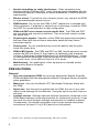
Maintenance and Handling
•
Cleaning the PRM. Do not use an abrasive cloth or volatile solvents to
clean any portion of the PRM or ZWT.
•
Disk handling. Keep disks away from magnets and magnetized objects,
including telephones, power-supply adapters, and monitors.
•
Magnet handling. Do not place a magnet on the PRM or ZWT.
•
PRM use. The PRM and ZWT are not waterproof or explosion-proof and
cannot be sterilized. Do not use them in the presence of flammable gas
mixtures including anesthetics, oxygen, or nitrous oxide.
•
Disconnecting the PRM. To completely disconnect the unit from the
power source, first use the On/Off button to turn the system off. Then
disconnect the power cord from the back of the unit.
•
PRM accessibility. Ensure the back of the unit is accessible at all times
so that the power cord can be disconnected.
Adverse Effects
None known.
System Features
The PRM uses the Model 6577 Sterilizable Telemetry Wand to communicate
with pulse generators and perform the following functions:
•
Interrogate and program the implantable pulse generator
•
Display records, store patient data, and allow the physician to evaluate
alternative prescription modes
•
Store patient session data that can be recalled later in the patient session
for analysis (for certain applications only)
•
Save patient data to the PRM hard drive or to a floppy disk
•
Generate printed reports that detail pulse generator functions, stored
patient data, and test results
•
Perform tests in an electrophysiology (EP) laboratory, in an operating
room, in an emergency room, or at a patient’s bedside
3
The PRM also:
•
Provides a direct interface between an external stimulator and an
implanted pulse generator for programmed electrical stimulation (PES)
during EP studies
•
May be used to support diagnostic activities pertaining to implanting,
programming, and monitoring Boston Scientific implantable pulse
generators. The PRM is not intended for use as an ECG monitor or
general diagnostic device
•
Prints simultaneous real-time surface ECG and telemetered signals
(intracardiac electrograms and event markers) using the internal
printer/recorder
•
Exports saved patient data from the fixed internal hard drive to a
removable USB pen drive
•
Provides the option to encrypt patient data prior to exporting to a USB
pen drive
•
Creates PDF report(s) from saved patient data and saves the report(s) to
the fixed internal hard drive or to an attached USB pen drive
•
Prints PDF report(s) to an external printer connected to the PRM
The PRM is equipped with the following features:
•
PRM function keys, including PROGRAM, STAT PACE, STAT SHOCK,
DIVERT THERAPY, and INTERROGATE
•
Printer/recorder function keys, including paper speed, calibrate, zero to
baseline, and paper feed
•
Touchscreen with tethered stylus
•
Color display screen
•
Floppy disk drive
•
Internal hard drive
•
High-speed thermal printer/recorder using 110 mm (4 in) wide paper
•
Connections for slaved stimulation via an external signal source (certain
applications only)
•
Parallel interface supports optional external printer
•
High-level analog outputs
•
USB ports used for patient data export to a standard USB pen drive,
connection to the 3140 Zoom Wireless Transmitter accessory, connection
to an external printer or used for software installation by Boston Scientific
personnel
4
•
ZIP™ telemetry, a cordless, hands-free radio frequency (RF)
communication option that allows the PRM to communicate with the pulse
generator
NOTE: To communicate wirelessly using ZIP telemetry, certain pulse
generators require the Model 3140 Zoom Wireless Transmitter. For
more information, refer to the associated product literature for the
pulse generator being interrogated. If ZIP telemetry performance is not
satisfactory, use the telemetry wand instead.
System Accessories
The ZOOM LATITUDE Programming System consists of the Model 3120 PRM
and the following accessories:
•
Model 3123 Antenna
•
Model 3140 Zoom Wireless Transmitter (ZWT)
•
Model 3141 USB Cable
•
Model 3124 Accessory Bag
•
Model 3130 Accessory Kit
•
Model 2902 AC Power Cord
•
Model 6577 Sterilizable Telemetry Wand
•
Model 6627 Patient Data Disks (10)
•
Model 6750 Surface ECG Patient Cable
•
Model 6979 Printer Paper (4)
•
Model 6629 ECG–BNC Slave Cable
To order accessories, contact Boston Scientific using the information on the
back cover.
WARNING: The use of any cables or accessories with the PRM or ZWT
other than those specified by Boston Scientific in this manual may result in
increased emissions or decreased immunity of the PRM or ZWT. Anyone
connecting such cables or accessories to the PRM or ZWT may be configuring
a medical system and is responsible to ensure that the system complies with
the requirements of IEC/EN 60601-1, Clause 16 for medical electrical systems.
Optional External Equipment
Optional external equipment can be used with the PRM. Contact your sales
representative to determine what external equipment can be used.
WARNING: Do not simultaneously touch the patient and any accessible
connector contacts on the PRM (e.g., USB, parallel port, external VGA monitor,
stimulation input, analog output, and expansion port).
CAUTION: Although optional external equipment connected to the PRM
meets leakage-current requirements for commercial products, it may not meet
the more stringent leakage requirements for medical products. Consequently,
all external equipment must be kept outside the patient environment (at least
1.5 m [4.9 ft] away from the patient).
5
External Printer
You can use an external printer if it is supported by the pulse generator
software application. Use only compatible external printers that have been
tested and qualified for use. Refer to the instructions to connect the cable
("Preparing the PRM for Use" on page 6).
PDF reports generated from saved patient data may be sent to an external
printer using the Patient Data Management utility. The utility is accessible from
the Patient Data Management button on the PRM startup screen.
External VGA Monitor
You can use an external VGA monitor that can synchronize to any horizontal
scan frequency.
NOTE: Equipment connected to the external connections must comply with
applicable standards (e.g., IEC/EN 60950-1 for data processing equipment
and IEC/EN 60601-1 for medical equipment). Anyone connecting such
cables or accessories to the PRM may be configuring a medical system and
is responsible to ensure that the system complies with the requirements of
IEC/EN 60601-1, Clause 16 for medical electrical systems.
Warranty Information
A limited warranty is packaged with the PRM. Unless otherwise agreed, the
PRM remains the property of Boston Scientific and Boston Scientific must
perform all necessary servicing and repair work. For additional copies, contact
Boston Scientific using the information on the back cover.
PREPARING THE PRM FOR USE
Make necessary external connections as directed below.
Prepare the Telemetry Wand
Prepare the 6577 Telemetry Wand for the sterile field by following the
sterilization procedures below, or by enclosing the wand in a sterile surgical
sheath.
CAUTION: The Model 6577 Telemetry Wand is shipped nonsterile. If the
telemetry wand is to be used in a sterile field, it must be actively sterilized
before use or enclosed in a disposable sterile surgical sheath during use.
Either ethylene oxide (EO) or steam may be used for active sterilization. Follow
the cleaning instructions ("Cleaning the PRM and Accessories" on page 23)
before beginning the sterilization process.
CAUTION: Remove the telemetry wand from all packaging material before
sterilizing it.
Ethylene oxide (EO) method: Follow the recommendations of the EO
sterilization equipment manufacturer and allow the specified aeration time
to fully elapse prior to use.
Steam method: Follow customary autoclave procedures for wrapped goods
and limit temperature to 132°C (-0°C, +5°C), 270°F (-0°F, +9°F).
6
NOTE: The Model 6577 Telemetry Wand has been tested for 25 sterilization
cycles and more than this number of sterilization cycles is not recommended.
Discard the wand any time surface cracks appear in the plastic and/or the
cable discolors or becomes worn, regardless of the number of completed
sterilization cycles.
Make Wand and Cable Connections
For connector locations, refer to the illustrations of the PRM right side, left
side, and rear panels (Figure 1 on page 7, Figure 2 on page 8, and Figure 3
on page 8).
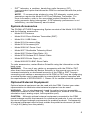
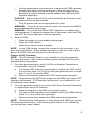
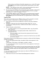
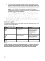
1.
Make the following connections on the right side of the PRM.
[1] Antenna for ZIP telemetry [2] Stimulator inputs [3] Air intake [4] Analog output channel [5]
Telemetry wand connector [6] ECG connector
Figure 1.
Right side panel of the PRM
•
Connect the telemetry wand to the telemetry wand connector.
•
Connect the Surface ECG Patient Cable to the ECG connector. This
connection is electrically isolated. Attach the surface electrodes to the
patient in a standard three-wire or five-wire configuration.
NOTE: The ECG subsystem may be sensitive to high-frequency
ambient noise when the ECG inputs are not terminated.
NOTE: The ECG function is intended to be used during patient
exams for tests such as pace threshold testing with body-contacting
connections.
NOTE: The surface ECG traces may exhibit noise interference
if the PRM is in close proximity to high-frequency electrosurgical
equipment. For corrective action, refer to the troubleshooting section
("Troubleshooting" on page 27).
•
2.
Connect a controller-stimulator cable to the PRM stimulator input
and then into the corresponding terminal on the electrical stimulation
source.
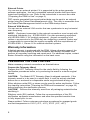
Make the following connections on the left side of the PRM.
7
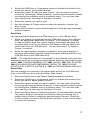
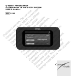
[1] On/Off button [2] External printer connector [3] USB ports [4] External VGA monitor connector
Figure 2.
Left side panel of the PRM
•
Connect the Model 3141 USB Cable to either USB port.
•
Connect the other end of the Model 3141 USB Cable to the Model
3140 Zoom Wireless Transmitter.
NOTE: To communicate wirelessly using ZIP telemetry, certain pulse
generators require the Model 3140 Zoom Wireless Transmitter. For
more information, refer to the associated product literature for the
pulse generator being interrogated. If ZIP telemetry performance is not
satisfactory, use the telemetry wand instead.
3.
•
Use a standard parallel printer or USB cable to attach an external
printer to the PRM printer connection.
•
Use a standard VGA cable to connect an external VGA monitor or
equivalent to the PRM VGA monitor connector.
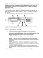
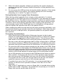
Make the following connections on the rear panel of the PRM.
[1] Equipotential stud [2] AC connector [3] Protective earth terminal
Figure 3.
•
8
Rear panel of the PRM
Connect the power cord to the alternating current (AC) connector on
the rear panel of the PRM.
•
Use the equipotential stud connection to equalize the PRM’s galvanic
potential with other electrical equipment. Using this terminal to
provide equalization may reduce electrical noise problems and the
possibility of indirect leakage currents between the PRM and other
electrical equipment.
CAUTION: Ensure the back of the unit is accessible at all times so that
the power cord can be disconnected.
•
Plug the power cord into the appropriate AC outlet.
WARNING: To avoid the risk of electric shock, only connect the PRM to
a grounded/earthed power source.
WARNING: Do not use the PRM or ZWT adjacent to or stacked with
other equipment. If adjacent or stacked use is necessary, check the PRM
and ZWT for normal operation in that configuration.
4.
Start the PRM.
•
Raise the screen to a comfortable viewing angle.
•
Press the On/Off button.
•
Wait for the startup screen to appear.
NOTE: During PRM startup, observe the screen for any messages. If an
error message appears, write a detailed description of the error and contact
Boston Scientific using the information on the back cover.
Prepare for ZIP Telemetry
NOTE: The ZIP telemetry feature is not available for all pulse generators.
For more information, refer to the associated product literature for the pulse
generator being interrogated.
1.
For pulse generators that use the 3140 Zoom Wireless Transmitter to
communicate using ZIP telemetry:
a.
For optimum ZIP telemetry communication, position the ZWT so that
it is no further than 3 m (10 ft) from the pulse generator and no closer
than 7.6 cm (3 in) from the PRM.
b.
Remove obstructions between the ZWT and the pulse generator.
NOTE: Repositioning the ZWT further away from the PRM may improve ZIP
telemetry performance. If ZIP telemetry performance is not satisfactory, use
the telemetry wand instead.
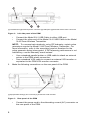
2.
For pulse generators that do not use the 3140 Zoom Wireless Transmitter
to communicate using ZIP telemetry:
a.
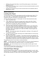
Raise the antenna on the PRM to its upright position.
b.
For optimum ZIP telemetry communication, position the PRM antenna
within 3 m (10 ft) of the pulse generator.
c.
Remove obstructions between the PRM and the pulse generator.
NOTE: Reorienting the PRM antenna or repositioning the PRM may improve
ZIP telemetry performance. If ZIP telemetry performance is not satisfactory,
use the telemetry wand instead.
9
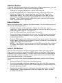
[1] Antenna
Figure 4.
Antenna in the upright position
USING THE PRM
Startup Screen
The PRM has a touchscreen and a tethered stylus allowing you to select items
such as buttons, checkboxes, and tabs that are displayed on the screen. Only
one item can be selected at a time.
CAUTION: Use the stylus supplied with the PRM; the use of any other object
could damage the touchscreen. Using the stylus may also improve accuracy.
10
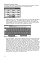
Figure 5.
Startup screen
When the PRM is powered On, the startup screen is displayed and contains
the following information:
•
The ECG Display, which shows four ECG traces for patient diagnosis
•
The Surface Rate, which displays the ventricular rate of the patient
•
The Details button, which expands the ECG Display to a full screen
•
The Quick Start® button, which is an automated method for starting the
appropriate application
•
The Patient Data Management button, which allows exporting, printing,
reading, or deleting patient data and/or reports on an attached USB pen
drive or the PRM hard drive
•
The Utilities button, which allows access to PRM information and setup
functions prior to accessing the application software
•
The About button, which allows the user to view, print, and save the PRM
configuration information (applications installed on the PRM and their
associated version numbers)
•
The Select PG button, which allows the desired PG (pulse generator)
application software to be selected and started
•
The date, time, and PRM information, which are located at the bottom,
center area
11
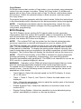
Changing Parameter Values
The screens for many of the features contain parameter information that can
be changed via either a palette window or a keyboard window.
Figure 6.
•
Palette window—To change a parameter value, first select the appropriate
parameter’s value box. A palette window will appear. Select a value
from the palette window by touching the desired value; the window will
automatically close when a selection is made. To close a window without
making a selection, touch the screen outside the window.
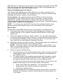
Figure 7.
•
Palette window
Keyboard window
Keyboard window—Some screens display value boxes that require unique
data to be entered, typically from a keyboard window. To enter data from
a keyboard window, first select the appropriate value box. A keyboard
window will appear. Touch the first character of the new value; it will appear
in the data-entry box in the graphic keyboard. Continue until the entire new
value appears in the box. To delete one character at a time, starting with
the last character, select the left arrow key on the graphic keyboard. Each
time the left arrow key is selected, a character will be deleted in the box.
To cancel any deletions or additions just made, select the Cancel Changes
button on the graphic keyboard. When all the appropriate characters have
been selected, select the Accept Changes button on the graphic keyboard.
NOTE: If, when the keyboard window initially appears, it contains data
in the data-entry box, select the Clear button on the graphic keyboard to
delete all the characters in the data-entry box.
12
Copy Button
On those screens that contain a Copy button, you can simply copy parameter
values from one screen to another. Select the Copy button. A window will
appear with a Copy From column and a Copy To column, with buttons below
the columns. Select the desired buttons in both columns, and then select
the Copy button.
To program the pulse generator with the copied values, follow the instructions
in the associated product literature for the pulse generator being interrogated.
NOTE: If additional parameters require reprogramming, repeat the copy
instructions. Multiple parameter changes can be programmed at one time
using batch programming.
ECG Display
The ECG Display shows surface ECG signals without pulse generator
interrogation when the surface ECG patient cable is connected to the PRM
and the electrodes are attached to the patient. (However, if a report is being
printed, the surface ECG does not display).
NOTE: The surface ECG may be printed on the internal printer/recorder;
press any speed key on the left-side keypad to record a surface ECG.
The PRM can display four surface traces of up to six limb leads or one chest
lead. The top displayed lead will be annotated with the pacing spike marker
if that feature is selected. To display the pacing spike markers correctly, the
Lead II electrodes must be connected to the patient regardless of which lead is
displayed. The Surface Rate will display the ventricular rate as the trace runs.
NOTE: The ECG functionality of the PRM is intended to support diagnostic
activities pertaining to implanting, programming, and monitoring Boston
Scientific implantable pulse generators. The PRM is not intended for use as an
ECG monitor or general diagnostic device.
WARNING: Operation of the PRM with physiological signals that are lower
than the minimum detectable amplitude may cause inaccurate results.
To expand the ECG Display to a full screen, select the Details button on the
startup screen. Use the following screen buttons to change the values and
appearance of the traces:
•
Trace Speed—Select the desired speed on the ECG display: 0 (stop),
25, or 50 mm/s
•
Trace 1, Trace 2, Trace 3, and Trace 4—Select the lead traces to be
displayed
•
Gain—Select the appropriate value to adjust the surface gain of the traces
that are captured on printouts
•
Enable Surface Filter—Select the checkbox to minimize noise on the
surface ECG
•
Display Pacing Spikes—Select the checkbox to show detected pacing
spikes, annotated by a marker on the top waveform
13
NOTE: The values as set up on the startup screen will be the defaults used
for the application traces. The corresponding values can be changed from
the Trace Selections screen while in the application. For detailed application
programming instructions, refer to the associated product literature for the
pulse generator being interrogated.
Intracardiac Electrogram
You can display intracardiac electrograms on the PRM screen. Also, you can
print both intracardiac electrograms and event markers on the internal printer.
For detailed instructions, refer to the associated product literature for the pulse
generator being interrogated.
Quick Start Button
The Quick Start button on the startup screen is used to automatically identify
and interrogate the implanted pulse generator. Place the telemetry wand over
the pulse generator, and select the Quick Start button.
A message window will appear, indicating one of the following conditions,
based on the implanted pulse generator:
•
Application startup in progress—If the software for the implanted pulse
generator is installed on the PRM, the PRM will identify the pulse
generator, start the correct application, and automatically interrogate the
pulse generator.
•
Software not installed—If the software application for the implanted pulse
generator is available for the PRM but not installed on it, a message
window will appear, identifying the pulse generator and stating that the
software is not installed on the PRM.
•
Software not available on PRM—If an older model of a pulse generator
is identified, a message window will appear, informing the user to use a
Model 2035 or Model 2901 programmer to interrogate and/or program the
pulse generator. The model number of the software module or application
will also be identified.
•
PG not identified—If a non-Boston Scientific pulse generator or one of
certain older models of Boston Scientific pulse generators is implanted,
a message window will appear, notifying the user that the wand is out of
range, telemetry noise is present, or the pulse generator is not identified.
To access the demonstration (DEMO) mode (or the Read Disk feature, which
is available in some applications), use the Select PG button located on the
toolbar below the startup screen to choose the pulse generator family instead
of using the Quick Start button.
Patient Data Management Utility
Saving patient data to the USB pen drive is a two-step process: (1) The PRM
allows you to save pulse generator data to the hard drive or a removable
floppy data disk. (2) Data saved to the hard drive can then be transferred to
a removable USB pen drive.
If a floppy disk is not inserted in the PRM disk drive, any disk operations
initiated within any application will be performed on space allocated on the
14
PRM hard drive. Data saved to the hard drive can then be exported to the USB
pen drive through the Export Data feature of the Patient Data Management
utility, accessible from the PRM startup screen.
Patient Data Management Features
The Patient Data Management utility allows you to export, transfer, print,
read, and delete patient data. On the Startup screen, select the Patient Data
Management button to access these features.
Privacy Notice: By exporting data from the PRM, you are assuming
responsibility for the privacy and security of that data. Printing, storing,
transferring, reading, and deleting of patient data must be performed in
compliance with applicable data privacy and security laws. Using the available
secure export methods is recommended.
NOTE: For information about PDF functionality available with the pulse
generator being interrogated, refer to the associated product literature.
Export Data
Patient data on the PRM hard drive can be exported to a USB pen drive.
1.
Select the Export tab on the Patient Data Management interface. The
system displays a list of patient records currently saved on the PRM
hard drive.
2.
Select the patient records you want to export. You can select all patient
records by selecting the Select All button, or select specific patient records
by selecting the checkbox next to a patient’s name. You can also undo
your selections by selecting the Deselect All button.
3.
Select the reports you want to export. The selected reports are created as
a PDF file from the data for each selected patient.
NOTE: Selecting a report is not required to export patient data. If you
want to export patient data only, leave the reports selections unchecked
and proceed to the next step.
4.
Select an export method below.
a.
To initiate export of the selected patient data, select the Export button.
Patient data in plain format is neither encrypted nor compressed on
the USB pen drive.
b.
To initiate export of the selected patient data with encryption, select
the Export with Password Protection button. Password protection
encrypts Protected Heath Information on the USB pen drive.
If a pen drive is being used to store patient data for the first time, the
system will prompt you to enter and confirm a password:
i.
Enter and confirm the password. The password must be
alphanumeric and contain at least six characters.
ii.
Select the Initialize button.
If the password does not meet the system requirements, the system
displays the Password Creation Failed dialog box and prompts you
to try again.
15
When using a non-Boston Scientific computer (e.g., a clinic PC), enter
your password to access encrypted patient data stored on the USB
pen drive.
NOTE: The USB pen drive used to store exported patient data cannot
contain both encrypted and non-encrypted patient data.
5.
Do not remove the USB pen drive during the export operation. If the export
operation fails for any reason, the system displays an error message
prompting you to select Try Again or Cancel.
6.
If the storage capacity of the USB pen drive is reached during the export
operation, the system displays a message stating that the export failed.
Insert another pen drive and select the Try Again button to continue with
the export.
Transfer Data
Files can be extracted from the USB pen drive to a PC, and can be viewed,
saved, e-mailed, or attached to an Electronic Medical Record.
1.
Insert the pen drive into any USB port on the PC and open Windows
Explorer.
2.
Navigate to the pen drive and locate the folder titled “bsc” (in the
root directory of the pen drive). Double-click this folder to access the
sub-folders.
3.
Select a transfer method below.
a.
To initiate transfer of non-encrypted patient data, copy the patient
data to the PC.
b.
To initiate transfer of encrypted patient data, double-click the
“ExtractAll.bat” file.
i.
When prompted, enter the pen drive password and choose a
destination folder.
ii.
Press the Extract All button to extract all of the files from the USB
pen drive to the PC.
Each patient record on the USB pen drive is stored in a folder with the following
naming conventions:
•
For non-encrypted patient data, the patient folder name appears in this
format:
<last name>-<first name>-<birth date>-<model>-<serial>
•
For encrypted patient data, the patient folder name appears in this format:
<model>-<serial>
The Export Data operation transfers the most recent patient data from the PRM
to the USB pen drive. It also moves the patient data from the previous sessions
to the “old” subfolder within the same patient folder on the USB pen drive.
Print Data
You can print reports for patient data saved on either the PRM hard drive or
an attached USB pen drive.
1.
16
Select the Print tab on the Patient Data Management interface.
2.
Select the USB Drive or Programmer option to indicate the location from
which you want to print patient records.
3.
Select the patient records you want to print. You can select all patient
records by selecting the Select All button, or select specific patient records
by selecting the checkbox next to a patient’s name. You can also undo
your selections by selecting the Deselect All button.
4.
Select the reports you want to print.
5.
Use the Number of Copies button to select the quantity of copies you
want to print.
6.
Select the Print button to print selected patient records and any associated,
selected reports.
Read Data
You can read patient data from the PRM hard drive or the USB pen drive.
1.
When you attempt to read data from the PRM hard drive or the USB pen
drive, the appropriate application is initiated. If the operation is unable
to read the patient data, the system displays a message indicating that
the application could not be started in Disk Mode or that the data could
not be read from the USB pen drive. You can then select Try Again or
Cancel to continue.
2.
When the read operation initiates successfully, the system displays a
message stating that Protected Health Information is being read from the
USB pen drive or the PRM hard drive.
NOTE: The Read Data feature is unavailable on the following pulse generator
applications which do not support reading patient data from removable storage
media: 2865 (CONTAK RENEWAL TR), 2880 (VIGOR), 2881 (DELTA/VISTA),
2890 (PULSAR/DISCOVERY/MERIDIAN/CONTAK TR), 2891 (PULSAR
II/DISCOVERY II/VIRTUS II/INTELIS II), 2892 (ALTRUA/INSIGNIA I/NEXUS I).
Delete Data
You can manage the contents of the patient data archive on the PRM hard
drive or the USB pen drive using the Delete Data feature.
1.
Select the Delete tab on the Patient Data Management interface.
2.
Select the USB Drive or Programmer option to indicate the location from
which you want to delete patient records.
3.
Select the patient records you want to delete. You can select all patient
records by selecting the Select All button, or select specific patient records
by selecting the checkbox next to a patient’s name. You can also undo
your selections by selecting the Deselect All button.
4.
Select the Delete button to initiate the deletion of selected patient records.
The system displays the Delete Confirmation dialog box asking you to
confirm that you want to delete the selected patient records. Select the
Confirm button to continue with the delete operation, or the Cancel button
to cancel the operation.
17
5.
When the delete operation initiates successfully, the system displays a
message stating that Protected Health Information is being deleted from
the system.
6.
Do not remove the USB pen drive during the delete operation. If the delete
operation fails for any reason, the system displays an error message
prompting you to select Try Again or Cancel.
Saving Episodes from Legacy Pulse Generators
When saving patient episodes from a legacy pulse generator, if a record
already exists on the PRM hard drive for that patient, new episodes are added
to the patient record. The patient record, however, contains an episode index
file which lists only the episodes saved during the most recent patient session.
Therefore, when saving patient episodes from a legacy pulse generator, if a
record already exists on the PRM hard drive for that patient, saving patient
data will replace the episode index file in the patient record.
When reading the patient record back into the pulse generator application, only
the episodes listed in the episode index file are displayed. When exporting the
patient record to a USB pen drive, all episodes present in the patient record
are exported.
Processing Considerations
•
When performing multiple patient follow-ups, be sure to start a new
session for each patient through the QUICK START or Select PG options
(rather than the application’s New Patient option). This will ensure that
data saved to the PRM hard drive during the previous session is not lost.
•
Be sure to save all pulse generator data to either a floppy disk or USB pen
drive before returning a PRM to Boston Scientific, as all patient and pulse
generator data will be erased from the PRM when it is returned for service.
•
No more than 400 unique patient records may be saved to the PRM. When
a pulse generator is interrogated, the PRM evaluates if there is a record on
file for this pulse generator, or if a new record needs to be created. If a new
record is needed, and the PRM is at the 400 record capacity, the oldest
record on file will be deleted to create space for the new patient record.
•
Up to 200 episodes can be saved to the PRM hard drive during a session
with a patient. Performing the Save All to Disk operation with a patient
who has more than 200 episodes will save only the oldest 200 episodes.
The system will then notify you that the disk is full and you will need to
restart the session and save up to 200 selected episodes.
•
If a patient has more than 200 episodes, it is recommended that you
perform a selective save operation instead of the Save All to Disk
operation.
•
With VITALITY applications, ensure a floppy disk is inserted when saving
profile data to Disk. Otherwise, the system will not prompt you to insert a
floppy disk and the profile data will be lost.
18
Utilities Button
If desired, before accessing the pulse generator software application, you can
select the Utilities button to perform the following actions:
•
Change the language displayed—Select the Setup tab.
•
Enable ZIP telemetry (if it is approved for use)—Select the Setup tab.
•
Modify the PRM clock—Select the Date and Time tab. Select the
appropriate date or time value box to change any of the date or time
parameters, and then select the appropriate value in the window that
displays. (The PRM and pulse generator clocks may be synchronized
once the application is accessed.)
About Button
Select the About button to display the About screen. Use the About screen to
perform the following actions:
•
Change the name of the institution. Select the value box next to
“Institution.” Refer to detailed instructions for entering new data using the
keyboard window (Figure 7 on page 12).
•
View the PRM model and serial number information.
•
Select the System Information tab and view the PRM system information
including the version numbers of the system software and the installed
software applications.
•
Print the PRM system information (known as the About report). To print the
About report, select the type of printer (internal or external), the number of
copies, and select the Print button.
NOTE: If a USB pen drive is inserted in the PRM when the About report
is printed, the report is also converted to a PDF and saved to the USB
pen drive.
Select PG Button
You can manually select the software application rather than using Quick
Start. Use this option to access the DEMO mode (or the Read Disk feature
available in some applications). You also can use this option to interrogate a
pulse generator, but you may find it more convenient to use the Quick Start
button described earlier in this manual.
To manually access the desired software application, perform the following
steps:
1.
Select the Select PG button on the startup screen.
2.
Select the applicable software application from the icons that represent
the available software applications. Each application communicates with
its pulse generator family.
3.
Choose the desired option to interrogate the pulse generator or use the
DEMO mode. (Some applications also will display the option to read
a patient data disk.)
19
a.
To become familiar with the software without interrogating a pulse
generator, select the DEMO button; the main application screen will
appear and the DEMO logo will appear at the top of the screen. The
software application screens displayed during the DEMO mode reflect
the features and programmable values of the pulse generator family.
NOTE: STAT PACE, STAT SHOCK, and DIVERT THERAPY
commands are functional in DEMO mode only if the telemetry wand is
positioned over the pulse generator.
b.
4.
To exit the DEMO mode, depending on which application you are
using, select the New Patient or Quit options from either the Utilities
button or the Exit button in the software application. For more
information about these options, refer to the associated product
literature for the pulse generator being interrogated.
To proceed with an interrogation session, or read data from a patient data
disk if available, refer to the associated product literature for the pulse
generator being interrogated.
Indicator Lights
The PRM has indicator lights on the upper left corner, above the screen. The
functions are described below.
Table 1.
Symbol
Indicator Lights
Indicator Light
Function
ZIP telemetry
Lit when ZIP telemetry
has been established
and interrogation or
programming of a
ZIP-enabled PG is
occurring
Wanded telemetry
Lit when wanded telemetry
has been established
and interrogation or
programming is occurring
On
Lit when the PRM is On
Keys
General PRM key functions are summarized below. For specific instructions
on how to operate the PRM keys and use the telemetry wand, refer to the
associated product literature for the pulse generator being interrogated.
20
[1] STAT PACE [2] DIVERT THERAPY [3] STAT SHOCK [4] PROGRAM [5] INTERROGATE
Figure 8.
Right-side keypad
The following description of the right-side keypad corresponds to the labels
in the illustration (Figure 8 on page 21). The PRM must be in telemetry
communication with the pulse generator for these functions to be available.
•
[1] Press STAT PACE to initiate emergency bradycardia pacing at
predetermined high-output parameters.
•
[2] Press DIVERT THERAPY to divert tachycardia therapy delivery.
•
[3] Press STAT SHOCK to initiate the delivery of an emergency maximum
energy shock.
•
[4] Press PROGRAM to transmit new parameter values to the pulse
generator.
•
[5] Press INTERROGATE to obtain information stored in the pulse
generator memory.
[1] Speed keys [2] Paper-feed key [3] Calibration key [4] Baseline Key
Figure 9.
Left-side keypad
The following description of the left-side keypad corresponds to the labels in
the illustration (Figure 9 on page 21).
•
[1] Press the speed keys to specify the paper speed for the internal
printer/recorder. The printout will show the date and time, lead(s)
being printed, gain setting, chart speed, and filter setting. To stop the
printer/recorder, press the speed key labeled “0” (zero).
21
•
[2] Press the paper-feed key to scroll the printer paper on the internal
printer/recorder.
•
[3] Press the calibration key to cause the internal printer/recorder to print a
1-mV calibration pulse.
•
[4] Press the baseline key to force the trace back to the baseline after a
defibrillation shock.
MAINTENANCE
Loading the Paper
The internal printer/recorder uses thermosensitive printing paper that is 110
mm (4 in) wide. To order Model 6979 printer paper refills, contact Boston
Scientific using the information on the back cover.
Use the following procedure to load paper into the internal printer/recorder:
1.
Open the printer door.
2.
If any sheets from the previous paper pack remain but did not feed,
remove them and rotate the roller with clean fingertips to remove any
small pieces of paper still under the printhead.
3.
Remove any packaging that might be present.
4.
Orient the pack such that the pagination mark (which is the small black
box that is visible inside the pack if you lift up the top sheet of paper) is
located nearest to the front of the PRM. (For a visual of how to orient
the paper, refer to the paper liner inside the PRM.) Insert the pack into
the printer/recorder.
NOTE: You must use paper with pagination markings or the paper will
not paginate properly.
5.
Unfold one sheet of paper, and allow the unfolded sheet to lie flat across
the well of the stylus.
6.
Close the printer door completely. The printer/recorder automatically will
begin the paper-loading sequence and will stop at the first pagination mark
after paper is detected. If the paper’s edges are wrinkled, let four or five
pages feed through the printer to self-align the paper to its proper position.
The printer/recorder is now ready to resume printing.
NOTE: To clear paper jams, open the printer door and use clean fingertips to
both remove the paper and rotate the roller in a clockwise direction.
WARNING: Do not simultaneously touch the patient and the parts inside
the printer door.
For information regarding loading paper into the optional external printer, refer
to the user manual for the external printer.
Thermal Paper Storage
Store the heat-sensitive paper for the internal printer/recorder in a cool, dark
environment. Do not attempt to erase the printer/recorder paper. Printed paper
will last approximately 30 days under direct fluorescent light. To ensure the
22
permanence of a patient’s record, store the printed paper away from direct
sunlight, heat, or fumes from organic compounds. Storage temperatures
above 60°C (140°F), sustained exposure to direct sunlight, or exposure to
high humidity, acetone, ammonia, alcohols, or other organic compounds may
cause the paper to discolor.
NOTE: If printed reports are to be kept for prolonged periods, you must make
a photocopy of the thermosensitive paper as this paper is not intended for
long-term retention and will lose legibility over time.
NOTE: Contact with adhesive tape or page protectors will fade the printing
after 30 days.
Cleaning the PRM and Accessories
Clean the housing and touchscreen of the PRM with a soft cloth lightly
dampened with water, isopropyl alcohol, a 5% bleach solution, or window
cleaner.
Clean the ZWT housing with a soft cloth lightly dampened with water, isopropyl
alcohol, a 5% bleach solution, or window cleaner. Do not allow any amount of
cleaning solution or moisture to come in contact with the USB port.
Clean the printer/recorder with a dry, soft brush to eliminate dust and particles
that may accumulate during printing and storage.
Clean the printer roller with an alcohol wipe.
CAUTION: Do not use an abrasive cloth or volatile solvents to clean any
portion of the PRM or ZWT.
The cables used with the PRM are not sterile when packaged and cannot
be sterilized. When necessary, clean the cables with a soft cloth dampened
with a mild cleaning solution such as green soap, green soap tincture (U.S.
Pharmacopeia), Borax, or alcohol-free hand soap. Use a fresh soft cloth
dampened with sterile water to remove residue. Towel-dry or air-dry the cables.
DO NOT use an ultrasonic cleaner. DO NOT immerse the cables. When
necessary, disinfect the ECG cable using a 2% glutaraldehyde solution (such
as Cidex) or a 10% bleach solution.
NOTE: Discard the ECG cables any time surface cracks appear in the
cables and/or the cables discolor, become visibly worn, or if labeling becomes
unreadable.
Clean the sterilizable telemetry wand in the same manner. DO NOT use an
ultrasonic cleaner. DO NOT immerse the telemetry wand. DO NOT allow
fluid to enter the wand cavity. Refer to "Preparing the PRM for Use" on page
6 for sterilization instructions.
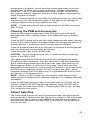
Patient Data Disk
The Patient Data Disk can be used to save patient data. Be certain that the
write-protect tab is closed on the disk (Figure 10 on page 24). The write-protect
tab must be closed in order to record data to the disk and to print reports. If
data cannot be recorded to the disk, check to see that the tab is positioned
to cover the hole.
23
[1] Write-protect tab closed (black tab covering hole) [2] Sliding shuttle
Figure 10.
Patient Data Disk
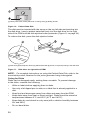
The disk must be inserted with the arrow on the top left side and pointing into
the disk drive. Insert a patient data disk firmly into the disk drive on the right
side of the PRM until the disk ejection button protrudes (Figure 11 on page 24).
To retrieve the disk, press the disk ejection button.
[1] Disk drive [2] Disk ejection button [3] Patient data disk [4] Arrow on top and pointing to the disk drive
Figure 11.
Disk drive on right side of PRM
NOTE: For complete instructions on using the Patient Data Disk, refer to the
associated product literature for the pulse generator being interrogated.
Caring for Disks
Disks can be damaged easily, making them unusable. To prevent damage
to the disks, consider the following:
•
Write on labels before applying them to disks.
•
Use only a felt-tipped pen to write on a label that is already applied to a
disk.
•
Keep food and beverages away from disks and away from the PRM.
•
Keep disks away from heat or direct sunlight. Disks should be stored at
temperatures between 5°C and 60°C (41°F and 140°F).
•
Keep disks dry and stored in a dry area (with a relative humidity between
8% and 80%).
•
Do not bend disks.
24
•
Do not attach paper clips, staples, or rubber bands to disks.
•
Do not try to open the sliding shutter that covers the disks (Figure 10 on
page 24).
•
Never touch the exposed disk area beneath the sliding shutter.
CAUTION: Keep disks away from magnets and magnetized objects, including
telephones, power-supply adapters, and monitors.
Operation and Storage
The PRM and ZWT require special handling. The hard-disk drive and the
floppy-disk drive of the PRM must be protected from abusive handling. To
protect the PRM and ZWT from damage, refer to the following information:
•
Do not turn off the PRM while the drive is accessing data.
•
Do not subject the PRM and ZWT to abusive shocks or vibrations.
•
When transporting the PRM and ZWT from an outside environment to an
inside environment, allow the PRM to acclimate to ambient temperature
before use.
•
Do not place heavy objects on the PRM surface when closed or when
in operation.
•
Do not place a magnet on the PRM or ZWT.
•
Do not pour or splash liquid into or onto the PRM or ZWT.
•
Do not strike, scratch, nick, or otherwise abuse the touchscreen surface.
•
Do not disassemble the PRM or ZWT.
•
Remove any disks from the drive prior to transporting the PRM.
•
Turn off the PRM, close all covers and doors, and put down the antenna
prior to transporting the PRM.
•
Unplug all external cables and cords prior to transporting the PRM.
•
Carefully secure the stylus in its holding tray before closing the PRM’s
cover.
Operate the PRM, ZWT and accessories within the following conditions:
•
Temperature range of 10°C to 35°C (50°F to 95°F)
•
Humidity between 25% and 90%
Transport and store the PRM and ZWT within the following conditions:
•
Temperatures between -40°C and 70°C (-40°F and 158°F)
•
Humidity of 25% to 95%
•
Pressure of 50 kPa to 106 kPa (7.252 psi to 15.374 psi)
If the PRM has been stored in cold conditions (less than 10°C [50°F]) or warm
conditions (more than 35°C [95°F]), turn it on and let the fan run for at least
one hour before use. The PRM and ZWT are capable of continuous operation
and will not shut off automatically if they are unused for an extended period
of time or if the PRM runs out of paper. Keep the air intake and outlet free
from obstruction.
25
CAUTION: The PRM and ZWT are not waterproof or explosion-proof and
cannot be sterilized. Do not use them in the presence of flammable gas
mixtures including anesthetics, oxygen, or nitrous oxide.
PRM Storage
1.
If using a patient data disk, remove the disk from the disk drive, and store
the disk in a safe place. You are responsible for the security of this disk
and the associated patient data.
2.
Exit the current software application.
3.
Press the On/Off button to turn off the power.
NOTE: Before unplugging the power cord to move the PRM, always exit the
software application and press the On/Off button to turn off the PRM.
4.
Unplug the power cord from the wall.
5.
Unplug all equipment cables from the back and side panels of the PRM.
6.
Lower the screen until the front latch locks in place.
NOTE: The PRM is not intended to be stored in an upright position (resting
on rear panel with handle on top).
NOTE: See each accessory’s product literature for transport and storage
conditions. Ensure each accessory is maintained within the appropriate limits.
Maintenance Check and Safety Measures
Maintenance Check
Prior to each use, you should perform a visual inspection and verify the
following:
•
Mechanical and functional integrity of the PRM, ZWT, cables, and
accessories.
•
Legibility and adherence of the PRM and ZWT labels.
•
Startup screen appears a few seconds after you turn on the PRM. (The
normal power-up process verifies that the PRM has passed its internal
checks and is ready for use.)
The PRM and ZWT contain no user-accessible components and must be
returned for replacement of any internal components.
Safety Measurements
National regulations may require that the user, manufacturer, or manufacturer
representative periodically perform and document safety tests of the device. If
such testing is required in your country, follow the testing interval and extent of
testing as regulated in your country. If you do not know the national regulations
in your country, please contact your local Boston Scientific representative.
If IEC/EN 62353 is a required standard in your country, but no specific testing
or interval is specified, it is recommended that you perform these safety tests
using the direct method as specified in IEC/EN 62353 at an interval of every 24
months. Refer to the Specifications table ("Specifications" on page 40).
26
Service
For questions regarding operation or repair of the PRM or ZWT, contact Boston
Scientific using the information on the back cover. The PRM and ZWT must be
serviced by Boston Scientific personnel only.
If the PRM or ZWT malfunction and require repair, help to ensure efficient
service by following these guidelines:
1.
Leave the configuration of the instrument exactly as it was at the time
of malfunction. Contact Boston Scientific using the information on the
back cover.
2.
Write a detailed description of the malfunction(s).
3.
Save printouts or other materials that illustrate the problem.
4.
If the PRM or ZWT must be returned to Boston Scientific for service,
pack it in the shipping container in which it was received or in a shipping
container provided by Boston Scientific.
5.
For the shipping address, contact Boston Scientific using the information
on the back cover.
For problems or questions that arise regarding operation or repair of the
optional external printer, contact the printer manufacturer or agent.
HANDLING
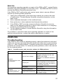
Troubleshooting
If the PRM or ZWT does not operate properly, check that electrical cords and
cables are securely connected and that cords and cables are in good working
order (i.e., free of visible defects). Possible causes and corrective actions for
problems are shown below. For external printer problems, refer to the manual
for the external printer.
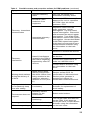
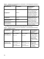
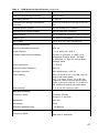
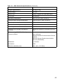
Table 2.
Possible causes and corrective actions for PRM problems
Symptom
Possible Cause
Corrective Action
No AC line voltage
Check that the power cord is
plugged securely into the rear
panel of the PRM.
Change to a different electrical
outlet.
Paper jam
Open the printer door and use
clean fingertips to both remove
the paper and rotate the roller in
a clockwise direction.
No paper
Add paper.
Paper misaligned
Reload paper.
Paper-feed obstruction
Clear obstruction from around
the paper supply.
Internal
printer/recorder does
not function
Internal
printer/recorder: paper-feed problems
27
Table 2.
Possible causes and corrective actions for PRM problems (continued)
Symptom
Possible Cause
Corrective Action
Internal
printer/recorder: no
print visible
Paper loaded upside
down
Reload paper.
Internal printer/record:
printing stops
Application did not
handle print request
If the touchscreen is not
responsive, turn off the PRM.
Turn on the PRM and try printing
any incomplete items again.
External printer does
not function
No paper; paper jam;
printer door open;
toner cartridge not
installed properly;
printer power not On;
printer not connected
Consult the manual for the
external printer to determine the
issue and corrective action.
Using disk created for
a previous model of
PRM or unformatted
floppy disk
Use only the Patient Data Disk.
Write-protect tab open
Close the write-protect tab.
Improper patient
connections
Recheck patient leads for
adequate skin contact and
correct limb lead placement.
Excessive radio
emissions from
equipment
Check surrounding area for
electrical equipment that is
powered on and not needed.
Move unneeded equipment
away from patient and/or PRM,
or turn off unneeded equipment.
Consult ECG textbooks for
additional ECG techniques.
Check for building-outlet ground
resistance less than 10 Ω, when
measured with low impedance
techniques, between the outlets
and from the outlets to other
grounded points in the room
(e.g., room bonding point,
cold-water pipe, exam table,
etc.).
Incorrect application
software or incorrect
PRM for pulse
generator
Install proper application
software for pulse generator in
use.
Incomplete telemetry
communication
Reposition wand over the pulse
generator; repeat interrogation.
Patient data disk error
Noise problems: ECG
Telemetry: no
communication
28
Table 2.
Possible causes and corrective actions for PRM problems (continued)
Symptom
Possible Cause
Corrective Action
Incorrect telemetry
wand
Use only the Model 6577
Sterilizable Telemetry Wand.
Excessive radio
emissions from
equipment
Reorient the PRM antenna (if
approved for use) or reposition
the PRM. Also see Noise
problems: ECG.
Incomplete telemetry
communication
Reposition wand over the
pulse generator; repeat
interrogation. Flip over wand;
repeat interrogation. Disconnect
and reconnect the wand; repeat
interrogation. Turn off the PRM,
and then turn on the PRM; repeat
interrogation. Use another Model
3120 PRM; repeat interrogation.
If this does not correct the issue,
contact Boston Scientific using
the information on the back
cover.
Telemetry: intermittent
communication
Reorient or relocate the devices.
Telemetry:
interference
Harmful interference
caused by the PRM or
the PRM is negatively
impacted by other RF
devices
Increase the separation between
the devices.
Connect the equipment to an
outlet on a different circuit.
Contact Boston Scientific using
the information on the back
cover.
Missing shock markers
during the delivery of
a shock
Noise during shock
delivery may prevent
the shock marker from
being received at the
maximum telemetry
distance of 6 cm (2.35
in)
Review surface ECG for
confirmation of delivered shock.
Review pulse generator’s
Arrhythmia Logbook for
confirmation of delivered shock.
Displayed clock does
not consistently keep
time after setting
Low battery
Return the PRM to Boston
Scientific for replacement of
clock battery.
Selecting inactive
buttons on the
touchscreen
Select active buttons.
Touchscreen does not
respond
Touchscreen not
functioning
Screen goes blank
Screen not functioning
PRM not responding
PRM not functioning
Turn off the PRM, and then turn
on the PRM. If this does not
correct the issue, contact Boston
Scientific using the information
on the back cover.
29
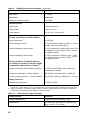
Table 3.
Possible causes and corrective actions for ZWT problems
Symptom
Green indicator light
on ZWT does not light
within 60 seconds of
powering on PRM
Telemetry: intermittent
communication
Possible Cause
Corrective Action
USB cable not
securely connected
to ZWT
Remove and reconnect both
ends of USB Cable.
USB cable damaged
Replace with Model 3141 USB
Cable only.
ZWT fault
Contact Boston Scientific using
the information on the back
cover.
Telemetry RF signal
obstructed
Assure that a clear line-of-sight
path exists between ZWT
and pulse generator. Repeat
interrogation.
Telemetry RF signal
interference
Reposition or reorient ZWT at
least 7.6 cm (3 in) or further from
the PRM. Repeat interrogation.
USB cable not
securely connected
to ZWT and PRM
Remove and reconnect both
ends of USB cable. Reposition
wand over the pulse generator
and repeat interrogation.
RF Telemetry fails
Reposition wand over
pulse generator and repeat
interrogation.
PRM software version
not current
Contact Boston Scientific using
the information on the back
cover.
Reorient or relocate the devices.
Telemetry:
interference
Harmful interference
caused by the ZWT or
the ZWT is negatively
impacted by other RF
devices
Increase the separation between
the devices.
Connect the equipment to an
outlet on a different circuit.
Contact Boston Scientific using
the information on the back
cover.
Using an External ECG Monitor with the PRM
Use the following accessories to set up the configuration described in this
section:
•
Model 6750 Surface ECG Patient Cable
•
Model 6629 ECG–BNC Slave Cable
•
Model 6577 Sterilizable Telemetry Wand
30
Figure 12.
External ECG Monitor Configuration
To display a tracing on an external ECG monitor and the PRM, set up
equipment as shown above (Figure 12 on page 31). In this example, the
surface ECG travels via the ECG cable (1) to the external ECG monitor (2),
then to the PRM via the ECG-BNC slave cable (3), connected to the PRM’s
ECG connector (4). Connect the telemetry wand (5) to the PRM’s telemetry
wand connector (6), ensuring that its cable does not cross any other cable.
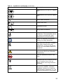
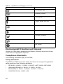
Symbols on Packaging
The following symbols may be used on packaging and labeling (Table 4 on
page 31):
Table 4.
Symbol
Symbols on packaging
Description
Reference number
Serial number
Use by
31
Table 4.
Symbol
Symbols on packaging (continued)
Description
Lot number
Date of manufacture
Non-ionizing electromagnetic
radiation; ZIP telemetry indicator
light
Sterilized using ethylene oxide
Consult instructions for use
Follow instructions for use
Temperature limitation
Authorized Representative in the
European Community
Manufacturer
Alternating current
On/Off button
USB
Parallel connector for printer
VGA output for external monitor
Analog output
Telemetry wand input and wanded
telemetry indicator light
32
Table 4.
Symbol
Symbols on packaging (continued)
Description
Defibrillation-proof type CF applied
part
Defibrillation-proof type BF applied
part
ECG cable connector
Paper form feed
Calibration pulse
Bring trace to baseline
Indicates the potential equalization
conductor. This connection allows
a common ground with other
equipment in a clinical setting.
Mark for nationally recognized
testing for safety standards
ONLY
RESTRICTED DEVICE: Federal
law (USA) restricts the sale,
distribution, or use of this device
to, by, or on the lawful order of a
physician.
Attention: consult accompanying
documents (ECG and Telemetry
connectors)
Port for authorized service use
only
Indicates the risk of electric shock;
do not remove the cover (or
back). Refer servicing to Boston
Scientific.
Waste, Electrical, and Electronic
Equipment (WEEE). Indicates
separate collection for electrical
and electronic equipment (i.e., do
not throw this device in the trash).
33
Table 4.
Symbols on packaging (continued)
Symbol
Description
On indicator light
Assembly number
This side up
Fragile, handle with care
Keep dry
Do not use hooks
Humidity limitations
Atmospheric pressure limitations
MR Unsafe
Environmental Protection and Disposal
Return the PRM and/or accessories to Boston Scientific at the end of their
useful lives for appropriate disposal.
Compliance Standards
The following standards apply to the PRM.
Safety Standards
The PRM and ZWT have been tested and found to comply with applicable
safety portions of the following standards:
•
IEC 60601-1:2005 + C1:2006 + C2:2007 + INT1:2008 + INT2:2009
•
ANSI/AAMI ES60601-1:2005 + C1:2009 + A2:2010
•
BS EN 60601-1:2006 + C1:2006 + C2:2007 + C3:2010
•
CAN/CSA-C22 No. 60601-1-08
34
Electromagnetic Compatibility Standards
The PRM has been tested and found to comply with the applicable portions of
the electromagnetic compatibility (EMC) standards:
•
FCC Part 15.209:2004 + 15.207:2004 + 15.249:2004
•
EN 302 195-2 V1.1.1:2004
•
EN 300 220-2 V2.1.2:2007
•
EN 301 489-1 V1.8.1:2008
•
EN 301 489-3 V1.4.1:2002
The ZWT has been tested and found to comply with the applicable portions of
the electromagnetic compatibility (EMC) standards:
•
EN 301 489–1 V1.9.2:2011
•
EN 301 489–27 V1.1.1:2004
•
EN 301 839–2 V1.3.1:2009
•
IC RSS-243:2010
NOTE:
Use special precautions regarding EMC during the installation and the use
of the PRM and ZWT, according to the EMC instructions given throughout
this manual. Refer to the details about the PRM and ZWT electromagnetic
emissions and immunity (Table 5 on page 36, Table 6 on page 36).
NOTE:
Use caution when using RF portable and mobile equipment in close
proximity to the PRM and ZWT. Refer to the details about the PRM and ZWT
electromagnetic immunity (Table 7 on page 38, Table 8 on page 39).
IEC 60601-1-2:2007 Information
This equipment has been tested and found to comply with the applicable
limits for medical devices to ANSI/AAMI/IEC 60601-1-2:2007 [or BS EN
60601-1-2:2007 + C1:2010 or Active Implantable Medical Device Directive
90/385/EEC]. This testing shows the device provides reasonable protection
against harmful interference in a typical medical installation. However, there is
no guarantee that interference will not occur in a particular installation.
Federal Communications Commission (FCC)
This device complies with Title 47, Part 15 of the FCC rules. Operation is
subject to the following two conditions:
•
This device may not cause harmful interference, and
•
This device must accept any interference received, including interference
that may cause undesired operation.
CAUTION: Changes or modifications not expressly approved by Boston
Scientific could void the user’s authority to operate the equipment.
Electromagnetic Emissions and Immunity
The electromagnetic emissions and immunity information is provided below.
35
Table 5. Guidance and manufacturer’s declaration - electromagnetic emissions for all equipment and systems
Emissions test
Electromagnetic
environment —
guidancea
Compliance
RF emissions
(CISPR 11)
Group 1
RF emissions
(CISPR 11)
Class A
Harmonic emissions
(IEC 61000-3-2)
Class A
Voltage fluctuations /
flicker emissions
(IEC 61000-3-2)
Complies
The PRM and ZWT
use RF energy only for
their internal function.
Therefore, RF emissions
are very low and are
not likely to cause any
interference in nearby
electronic equipment.
The PRM and ZWT are
suitable for use in all
establishments other
than domestic and those
directly connected to
the public low-voltage
power supply network that
supplies buildings used for
domestic purposes.
a. The PRM and ZWT are intended for use in the electromagnetic environment specified in the table.
The customer or the user should ensure they are used in such an environment.
Table 6. Guidance and manufacturer’s declaration - electromagnetic immunity for all equipment systems
Immunity test
IEC 60601 test
level
Compliance level
Electromagnetic
environment —
guidancea
Electrostatic
discharge (ESD)
(IEC 61000-4-2)
±6 kV contact
±6 kV contact
±8 kV air
±8 kV air
Floors should be
wood, concrete,
or ceramic tile. If
floors are covered
with synthetic
material, the
relative humidity
should be at least
30%.
±2 kV for
power-supply lines
±2 kV for
power-supply lines
±1 kV for
input/output lines
±1 kV for
input/output lines
Electrical fast
transient / burst
(IEC 61000-4-4)
36
Mains power
quality should
be that of a
typical commercial
or hospital
environment.
Table 6. Guidance and manufacturer’s declaration - electromagnetic immunity for all equipment systems (continued)
Immunity test
IEC 60601 test
level
Compliance level
Electromagnetic
environment —
guidancea
Surge (IEC
61000-4-5)
±1 kV line(s) to
line(s)
±1 kV differential
mode
±2 kV line(s) to
earth
±2 kV common
mode
Mains power
quality should
be that of a
typical commercial
or hospital
environment.
<5% UT (>95%
dip in UT ) for 0.5
cycleb
<5% UT (>95% dip
in UT ) for 0.5 cycle
40% UT (60% dip
in UT ) for 5 cycles
40% UT (60% dip
in UT ) for 5 cycles
70% UT (30% dip
in UT ) for 25 cycles
70% UT (30% dip
in UT ) for 25 cycles
<5%UT (>95% dip
in UT ) for 5 sec
<5%UT (>95% dip
in UT ) for 5 sec
3 A/m
3 A/m
Voltage dips, short
interruptions, and
voltage variations
on power-supply
input lines (IEC
61000-4-11)
Power frequency
(50/60 Hz)
magnetic field (IEC
61000-4-8)
Mains power
quality should
be that of a
typical commercial
or hospital
environment. If the
user of the PRM
requires continued
operation during
power mains
interruptions, it
is recommended
that the PRM be
powered from an
uninterruptible
power supply or
a battery.
Power frequency
magnetic fields
should be at levels
characteristic of a
typical location in a
typical commercial
or hospital
environment.
a. The PRM and ZWT are intended for use in the electromagnetic environment specified in the table.
The customer or the user should ensure they are used in such an environment.
b. UT is the AC mains voltage prior to application of the test level.
37
Table 7. Guidance and manufacturer’s declaration - electromagnetic immunity for equipment and systems that are not life supporting
Immunity test
IEC 60601 test
level
Compliance level
Electromagnetic
environmenta —
guidanceb
Conducted RF
(IEC 61000-4-6)
3 Vrms
150 kHz to 80 MHz
3 Vrms
Radiated RF
(IEC 61000–4-3)
3 V/m
80 MHz to 2.5 GHz
3 V/m
Portable and
mobile RF
communications
equipment should
be used no closer
to any part of
the PRM or
ZWT, including
cables, than the
recommended
separation
distance calculated
from the equation
applicable to the
frequency of the
transmitter.
Recommended
separation
distance
d = 1.2 √P
d = 1.2 √P (80 MHz
to 800 MHz)c
d = 2.3 √P (800
MHz to 2.5 GHz)
where P is the
maximum output
power rating of the
transmitter in watts
(W) according to
the transmitter
manufacturer
and d is the
recommended
separation
distance in meters
(m).
38
Table 7. Guidance and manufacturer’s declaration - electromagnetic immunity for equipment and systems that are not life supporting (continued)
Immunity test
IEC 60601 test
level
Compliance level
Electromagnetic
environmenta —
guidanceb
Field strengths
from fixed RF
transmitters, as
determined by an
electromagnetic
site surveyd should
be less than the
compliance level
in each frequency
range.e
Interference may
occur in the vicinity
of equipment
marked with the
following symbol:
a. The PRM and ZWT are intended for use in the electromagnetic environment specified in the table.
The customer or the user should ensure they are used in such an environment.
b. These guidelines may not apply in all situations. Electromagnetic propagation is affected by
absorption and reflection from structures, objects, and people.
c. At 80 MHz and 800 MHz, the higher frequency range applies.
d. Field strengths from fixed transmitters, such as base stations for radio (cellular/cordless)
telephones and land mobile radios, amateur radio, AM and FM radio broadcast, and TV broadcast
cannot be predicted theoretically with accuracy. To assess the electromagnetic environment due
to fixed RF transmitters, an electromagnetic site survey should be considered. If the measured
field strength in the location in which the PRM and ZWT are used exceeds the applicable RF
compliance level shown in the table, they should be observed to verify normal operation. If
abnormal performance is observed, additional measures may be necessary, such as reorienting
or relocating the PRM and ZWT.
e. Over the frequency range 150 kHz to 80 MHz, field strengths should be less than 3 V/m.
Table 8. Recommended separation distances between portable and mobile RF
communications equipment, and the PRM / ZWT
Rated maximum
output power of
transmitterb c
W
Separation distance according to frequency of transmittera
m
150 kHz to 80 MHz
d = 1.2 √P
80 MHz to 800
MHzd
d = 1.2 √P
800 MHz to 2.5
GHz
d = 2.3 √P
0.01
0.12
0.12
0.23
0.1
0.38
0.38
0.73
1
1.2
1.2
2.3
39
Table 8. Recommended separation distances between portable and mobile RF
communications equipment, and the PRM / ZWT (continued)
Rated maximum
output power of
transmitterb c
W
Separation distance according to frequency of transmittera
m
150 kHz to 80 MHz
d = 1.2 √P
80 MHz to 800
MHzd
d = 1.2 √P
800 MHz to 2.5
GHz
d = 2.3 √P
10
3.8
3.8
7.3
100
12
12
23
a. The PRM and ZWT are intended for use in an electromagnetic environment in which radiated
RF disturbances are controlled. The customer or the user can help prevent electromagnetic
interference by maintaining a minimum distance between portable and mobile RF communications
equipment (transmitters), the PRM, and ZWT as recommended in the table, according to the
maximum output power of the communications equipment.
b. These guidelines may not apply in all situations. Electromagnetic propagation is affected by
absorption and reflection from structures, objects, and people.
c. For transmitters rated at a maximum output power not listed in the table, the recommended
separation distance d in meters (m) can be estimated using the equation applicable to the
frequency of the transmitter, where P is the maximum output power rating of the transmitter in
watts (W) according to the transmitter manufacturer.
d. At 80 MHz and 800 MHz, the separation distance for the higher frequency range applies.
Specifications
Table 9.
PRM Nominal Specifications
Characteristic
Nominal
Safety classification
PRM: Class I.
ECG connection: Type BF,
defibrillation-protected.
Telemetry-wand connection: Type CF,
defibrillation-protected
Ingress protection rating: IPX0
Dimensions
47 cm (18.5 in) deep, 36.8 cm (14.5 in)
wide, 12.1 cm (4.75 in) high
Weight (approximate)
9.8 kg (21.5 lb)
Power rating
100–120 V 60 Hz, 220–240 V 50 Hz,
3.8/1.9 A
Power cord
2.4 m (8 ft), 100–240 V. Reliable
grounding is achieved only when
equipment is connected to receptacle
marked with “Hospital only” or “Hospital
grade.”
Duty cycle
Continuous
Operating temperature
10°C to 35°C (50°F to 95°F)
Transport and storage temperature
-40°C to 70°C (-40°F to 158°F)
Operating humidity
25% to 90%
40
Table 9.
PRM Nominal Specifications (continued)
Characteristic
Nominal
Transport and storage humidity
25% to 95%
Operating altitude
≤ 2000 m
Transport and storage atmospheric
pressure
50 kPa to 106 kPa (7.252 psi to 15.374
psi)
External printer support
DB 25 parallel port connector
External VGA monitor support
DB 15 VGA port connector
Analog output
± 1 V output via seven-pin DIN connector
Battery type
DL 2450 or equivalent
ECG cable
3.9 m to 4.3 m (12.7 ft to 14.0 ft)
ECG performance
Minimum amplitude detected
4.56 µV
Lead selection
I, II, III, aVR, aVL, aVF, V
Intrinsic ventricular rate display
30 bpm to 120 bpm ± 4 bpm on a
three-beat average basis; 120 bpm
to 240 bpm ± 8 bpm on a three-beat
average basis
Input impedance
> 2.5 M Ω
Electrode offset tolerance
300 mV
Storage resolution
800 samples/sec, 4.56 µV
Filter settings
ON: 0.5 Hz to 25 Hz, ± 0.2 dB, with 50
and 60 Hz notch filters;
OFF: 0.5 Hz to 70 Hz, ± 0.2 dB, flat
response, without 50 and 60 Hz notch
filters; 0.05 Hz to 100 Hz, + 0.2 dB/-3.0
dB, without 50 and 60 Hz notch filters
Gain settings
1, 2, 5, 10, 20 mm/mV ± 25%
Wanded telemetry
Frequency band
Transmit: 50 kHz
Receive: 0–100 kHz
Bandwidth
100 kHz
Modulation
OOK
Effective radiated power
-1.2 dBµV/m
ZIP telemetry (ISM)
Frequency band
ISM (902 to 928 MHz)
41
Table 9.
PRM Nominal Specifications (continued)
Characteristic
Nominal
Bandwidth
< 1 MHz
Modulation
ASK/OOK
Effective radiated power
-1.3 dBm
Internal printer
Paper type
Thermosensitive
Paper width
110 mm (4 in)
Chart speed
10, 25, 50, 100 mm/sec
Electrical Safety Testing-Reference for
testing according to the IEC 60601b
Earth resistance
≤ 100 mΩ
Earth leakage current
≤ 5 mA Normal Condition (NC), ≤ 10 mA
Single Fault Condition (SFC)
Patient leakage current wand
≤ 10 µA Normal Condition (NC) and ≤ 50
µA Single Fault Condition (SFC) (mains
on applied parts)
Patient leakage current ECG
≤ 100 µA Normal Condition (NC), ≤ 500
µA Single Fault Condition (SFC) (mains
on applied parts)
Electrical Safety Testing-Reference
for testing according to the IEC 62353
(Installation, Maintenance, Repair)ab
Earthbond testing (Groundbond testing)
≤ 300 mΩ including power cable not
exceeding 3 meters
Equipment leakage — direct method
ECG (BF) and Wand (CF) : ≤ 500 µA
Patient leakage current — direct method
ECG (BF) ≤ 500 µA, Wand (CF): ≤ 50 µA
Safety Features
Defibrillator protection
to 5000 V 400 J
a. For questions regarding operation or repair of the PRM, contact Boston Scientific using the
information on the back cover. The PRM must be serviced by Boston Scientific personnel only.
b. After successfully completing safety testing, verify the PRM continues to meet the essential
performance as defined in the beginning of this manual.
Table 10.
ZWT Nominal Specifications
Characteristic
Nominal
Safety classification
Ingress protection rating: IPX0
Dimensions
17.6 cm (6.9 in) wide, 17.3 cm (6.8 in)
high, 4.6 cm (3 in) deep
42
Table 10.
ZWT Nominal Specifications (continued)
Characteristic
Nominal
Weight (approximate)
0.6 kg (1.3 lb)
Power rating
5 V DC
Power cord
Power supplied via USB data cable
Duty cycle
Continuous
Operating temperature
10°C to 35°C (50°F to 95°F)
Transport and storage temperature
-40°C to 70°C (-40°F to 158°F)
Operating humidity
25% to 90%
Transport and storage humidity
25% to 95%
Operating altitude
≤ 2000 m
Transport and storage atmospheric
pressure
50 kPa to 106 kPa (7.252 psi to 15.374
psi)
ZIP telemetry (MICS/MedRadio)
Frequency Band
402–405 MHz
Medical Implant Communication Service
(MICS)
Medical Device Radiocommunication
Service (MedRadio)
Bandwidth
< 300 KHz
Modulation
FSK
Effective radiated power
22.4 µW (-16.5 dBm)
43
44
Manufacturer
Boston Scientific
4100 Hamline Avenue North
St. Paul, MN 55112-5798 USA
www.bostonscientific.com
1.800.CARDIAC (227.3422)
+1.651.582.4000
© 2014 Boston Scientific Corporation or its affiliates.
All rights reserved.
357434-009 EN US 2014-01
FCC ID: ESCCRM312005
IC: 4794A-CRM31205
DISCARD WITH
ELECTRONIC
WASTE
*357434-009*