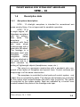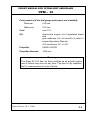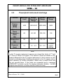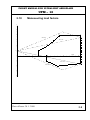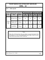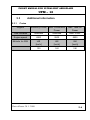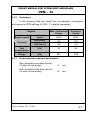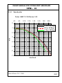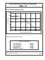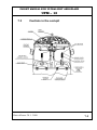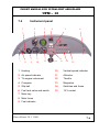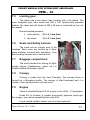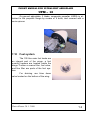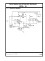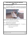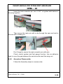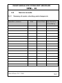
1
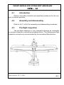
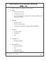
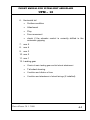
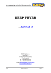
Operations and Flight Manual
UFM – 13 LAMBADA
Serial No. 105/13
Date of Issue: 30/01/2008
Urban Air s.r.o., T.G.Masaryka 897, 562 01 Ústí nad Orlicí, Czech Republic,
Tel./fax: +420 465 582 573, E-mail: [email protected]
FLIGHT MANUAL FOR ULTRALIGHT AEROPLANE
UFM – 13
0. Table of Contents
0.
Table of Contents...................................................................0-11
1.
General......................................................................................1-0
2.
Limitations ................................................................................2-0
3.
Emegency procedures ...........................................................3-0
4.
Normal procedures ..................................................................4-0
5.
Performance .............................................................................5-0
6.
Weight and Balance.................................................................6-0
7.
Aeroplane and Systems Description .....................................7-3
8.
Aeroplane handling, servicing and maintenance ...............8-13
9.
Supplements.............................................................................9-0
Date of Issue: 30. 1. 2008
0-1
FLIGHT MANUAL FOR ULTRALIGHT AEROPLANE
UFM – 13
Section 1
1. General
1.1
1.2
1.3
1.4
1.5
Introduction..................................................................................1-1
Certification basis ........................................................................1-1
Warnings, cautions and notes.....................................................1-3
Descriptive data...........................................................................1-4
Three-view drawing .....................................................................1-7
Date of Issue: 30. 1. 2008
1-0
FLIGHT MANUAL FOR ULTRALIGHT AEROPLANE
UFM – 13
1.1
Introduction
This Flight Manual provides information useful for the safe and efficient operation of UFM - 13 ultralight aeroplane.
It also contains supplemental data supplied by the aeroplane
manufacturer.
1.2
Certification basis
This type of aeroplane has been designed in compliance with
„Požadavky na letovou způsobilost Sportovních létajících zařízení
Ultralehké letouny řízené aerodynamicky UL-2 část I (Ultralight Airworthiness Requirements UL-2, part I)“, that is the valid Certification basis for
the ULTRALIGHT category aeroplanes approved by the Czech Amateur
Light Aircraft Association ( www.laacr.cz ).
Date of Issue: 30. 1. 2008
1-1
FLIGHT MANUAL FOR ULTRALIGHT AEROPLANE
UFM – 13
Date of Issue: 30. 1. 2008
1-2
FLIGHT MANUAL FOR ULTRALIGHT AEROPLANE
UFM – 13
1.3
Warnings, cautions and notes
The following definitions apply to warnings, cautions and notes in
the flight manual.
Warning
Means that the non-observation of the corresponding procedure leads to an immediate or important degradation of the flight
safety.
Caution
Means that the non-observation of the corresponding procedure leads to a minor or to a more or less long term degradation of the
flight safety.
Note
Draws the attention of any special item not directly related to
safety but which is important or unusual.
Date of Issue: 30. 1. 2008
1-3
FLIGHT MANUAL FOR ULTRALIGHT AEROPLANE
UFM – 13
1.4
1.4.1
Descriptive data
Aeroplane description
UFM - 13 ultralight aeroplane is intended for recreational and
cross-country flying. It is not approved for aerobatic operation.
UFM - 13 is
a single engine, allfibreglass aeroplane
with two side-byside seats. The
aeroplane
is
equipped with fixed
two main wheel
undercarriage with a
steer able tail wheel.
The fuselage is a
fibreglass shell with
fibreglass
seats
integrated.
Safety
belts are attached to
the seats and to a
shelf intended for
putting off lightweight objects (headphones, maps, etc.).
The wing is a monospar construction with a sandwich skin composed of two layers of fibreglass and special foam. Control surfaces and
empennage is of the same construction.
The aeroplane is controlled by dual push-pull control system, only
rudder drive is controlled by cable. The ailerons and elevator are controlled
by the control stick located between the pilot's legs (co-pilot's). The rudder
is controlled by the rudder pedals, flaps are operated by a control lever
located between the pilots on the fuselage main spar.
Date of Issue: 30. 1. 2008
1-4
FLIGHT MANUAL FOR ULTRALIGHT AEROPLANE
UFM – 13
1.4.2
Basic Technical data
Wing
Span/span with wing extension ........................ 12.94/14.95m
Area/area with wing extension.......................... 12.16/12.87m
2
MAC .................................................................... 0.987 m
Loading/loading area with wing extension ....... 37/34.9kg/m
2
Flaperon
area ..................................................................... 0.82 m
2
Fuselage
length .................................................................. 6.6
m
width.................................................................... 1.08 m
height .................................................................. 1.95 m
Horizontal tail unit
span .................................................................... 2.5
m
area ..................................................................... 1.3
m
2
elevator area ....................................................... 0.45 m
2
Date of Issue: 30. 1. 2008
1-5
FLIGHT MANUAL FOR ULTRALIGHT AEROPLANE
UFM – 13
Vertical tail unit
height .................................................................. 1.2
m
area ..................................................................... 1.1
m
2
rudder area ......................................................... 0.44 m
2
Landing gear
wheel track .......................................................... 1.54 m
wheel base.......................................................... 4.16 m
main wheel diameter........................................... 0.4
m
tail wheel diameter .............................................. 0.2
m
Date of Issue: 30. 1. 2008
1-6
FLIGHT MANUAL FOR ULTRALIGHT AEROPLANE
UFM – 13
1.5
Three-view drawing
Date of Issue: 30. 1. 2008
1-7
FLIGHT MANUAL FOR ULTRALIGHT AEROPLANE
UFM – 13
Section 2
2. Limitations
2.1
2.2
2.3
2.4
2.5
2.6
2.7
2.8
2.9
2.10
2.11
2.12
2.13
2.14
2.15
2.16
Introduction..................................................................................2-1
Airspeed ......................................................................................2-1
Airspeed indicator markings........................................................2-2
Powerplant ..................................................................................2-3
Powerplant instrument markings.................................................2-5
Miscellaneous instrument markings ............................................2-6
Weight .........................................................................................2-7
Centre of gravity ..........................................................................2-7
Approved manoeuvres ................................................................2-7
Manoeuvring load factors............................................................2-8
Crew ............................................................................................2-9
Kinds of operation .......................................................................2-9
Fuel............................................................................................2-10
Maximum passenger seating ....................................................2-10
Other limitations ........................................................................2-11
Limitation placards ....................................................................2-12
Date of Issue: 30. 1. 2008
2-0
FLIGHT MANUAL FOR ULTRALIGHT AEROPLANE
UFM – 13
2.1
Introduction
Section 2 includes Operating limitations, instrument markings, and
basic placards necessary for safe operation of the aeroplane, its engine,
standard systems and standard equipment.
2.2
Airspeed
Airspeed limitations and their operational significance are shown
below:
Airspeed
VNE
VNO
Never exceed
speed
Maximum
structural
cruising speed
IAS
[km/h]
200
145
VA
Manoeuvring
speed
135
VFE
Maximum Flap.
Extension speed
110
Date of Issue: 30. 1. 2008
Remarks
Do not exceed this speed in
any operation.
Do not exceed this speed
except in smooth air, and
then only with caution.
Do not make full or abrupt
control movement above
this speed, because under
certain conditions the aircraft may be overstressed
by full control movement.
Do not exceed this speed
with flaps extended
2-1
FLIGHT MANUAL FOR ULTRALIGHT AEROPLANE
UFM – 13
2.3
Airspeed indicator markings
Airspeed indicator markings and their colour-code significance are
shown below:
Marking
Range or value
[IAS km/h]
White
arc
Green
arc
Significance
70 - 110
Positive Flap Operating Range
80 – 145
Normal Operating Range
Yellow
arc
145 – 200
Manoeuvres must be conducted with caution and only in
smooth air.
Red
line
200
Maximum speed for all operations.
Date of Issue: 30. 1. 2008
2-2
FLIGHT MANUAL FOR ULTRALIGHT AEROPLANE
UFM – 13
2.4
Powerplant
Engine Manufacturer : Bombardier-Rotax GMBH
Engine Model:
Rotax 912 UL
Power:
Max. Take-off:
59,6 kW / 80 hp
Max. Continuous: 58 kW / 78 hp
at 5500 rpm
Cruising:
53 kW / 71 hp
at 4800 rpm
Engine RPM:
Max. Take-off:
5800 rpm, max. 5 min.
Max. Continuous: 5500 rpm
Cruising:
4800 rpm
Idling:
1400 rpm
Cylinder head temperature:
Minimum:
60 °C
Maximum:
150 °C
Oil temperature:
Minimum:
50 °C
Maximum:
140 °C
Opt. operating:
90 °C – 100 °C
Date of Issue: 30. 1. 2008
2-3
FLIGHT MANUAL FOR ULTRALIGHT AEROPLANE
UFM – 13
Fuel pressure (if the fuel gauge and sensor are installed):
Minimum:
0.40 bar
Maximum:
0.15 bar
Fuel:
see 2.13
Oil:
Automotive engine oil of registered brand
with
gear additives, but not aircraft oil (refer to
engine Operator’s Manual).
API classification „SF“ or „SG“.
Propeller:
VARIA 160/2/R
Propeller diameter:
1600 mm
Warning
The Rotax 912 UL has not been certified as an aircraft engine
and its failure may occur at any time. The pilot is fully responsible for consequences of such a failure.
Date of Issue: 30. 1. 2008
2-4
FLIGHT MANUAL FOR ULTRALIGHT AEROPLANE
UFM – 13
2.5
Powerplant instrument markings
Function
Engine
speed
(RPM)
Cylinder
Head
Temperature
(CHT)
[°C]
Oil
Temperature
[°C]
Oil
Pressure
[bar]
Minimum
Limit
Normal
Operating
Range
Caution
Range
Maximum
Range
1400
1400-5500
5500-5800
5800
60
60-100
100-150
150
50
90-110
110-140
140
1.5
1.5 – 4.0
4.0 – 5.0
7.0 cold
engine
starting
Note
st
In the TL engine instrument memory are stored the limits of 1 and
nd
2 level for Rotax 912 engine. The values of limits are stated in Operator’s Manual for the TL engine instrument. A limit overrun is indicated by indicating lamp flashing and stored in the TL engine instrument memory for further evaluation. Make note of these limits and
do not exceed them. If the limits are exceeded and a message
„SERVICE“ is shown on the TL engine instrument display - contact
engine manufacturer or Rotax Service Centre for help.
Date of Issue: 30. 1. 2008
2-5
FLIGHT MANUAL FOR ULTRALIGHT AEROPLANE
UFM – 13
2.6
•
Miscellaneous instrument markings
Fuel gauge
A fuel reserve of 7 litres is indicated by a yellow warning lamp.
Date of Issue: 30. 1. 2008
2-6
FLIGHT MANUAL FOR ULTRALIGHT AEROPLANE
UFM – 13
2.7
Weight
Empty weight …………………………………… 307 kg
NOTE
Actual empty weight is stated in SECTION 6, par. 6.2
Max. take-off weight........................................ 520 kg
Max landing weight ......................................... 520 kg
Max. baggage weight.......................................... 4 kg
2.8
Centre of gravity
Empty aeroplane C.G. position (standard) ... 32,0 %MAC
Operating C.G. range................................. 20 - 35 %MAC
2.9
Approved manoeuvres
Aeroplane Category: NORMAL
The aeroplane is approved for Normal and Manoeuvres listed below:
-
Steep turn not exceeding 60° bank
Warning
Aerobatics, intentional spins and stalls are prohibited!
Date of Issue: 30. 1. 2008
2-7
FLIGHT MANUAL FOR ULTRALIGHT AEROPLANE
UFM – 13
2.10
Manoeuvring load factors
6
5
A
D
4
Ude=15 m/s
Ude=7.5 m/s
3
2
n 1
v [km/h]
0
0
50
100
150
200
-1
Ude=-7.5 m/s
E
-2
Ude=-15 m/s
G
-3
-4
Date of Issue: 30. 1. 2008
2-8
FLIGHT MANUAL FOR ULTRALIGHT AEROPLANE
UFM – 13
2.11
Crew
Minimum crew..................................................... 1
Maximum crew.................................................... 2
2.12
Kinds of operation
Day VFR flights only.
Instruments and equipment for VFR flights:
1 Airspeed indicator (marked according to 2.3)
1 Altimeter
1 Vertical speed indicator
1 Magnetic compass
1 Bank indicator
2 Safety harnesses
Date of Issue: 30. 1. 2008
2-9
FLIGHT MANUAL FOR ULTRALIGHT AEROPLANE
UFM – 13
2.13
Fuel
-
automotive premium grade gasoline, leaded, according to DIN
516000,Ö-NORM C 1103
-
EUROSUPER RON 95 unleaded accord. to DIN 51607,ÖNORM 1100
-
AVGAS 100 LL
-
Due to higher lead content in AVGAS, the wear of valve seats
and deposits in the combustion chamber will increase. Therefore, use AVGAS only if other fuel types are not available.
-
BA 95 Natural is recommended for Czech Republic
For other suitable fuel types refer to the engine Operator’s Manual.
2.14
Maximum passenger seating
Number of seat .............................................. 2
Minimum crew weight .................................. 65 kg
Maximum crew weight ................................. see 6.2
Warning
Never exceed 520 kg Max. Take-Off Weight.
Date of Issue: 30. 1. 2008
2-10
FLIGHT MANUAL FOR ULTRALIGHT AEROPLANE
UFM – 13
2.15
•
Other limitations
No smoking aboard the aeroplane.
Date of Issue: 30. 1. 2008
2-11
FLIGHT MANUAL FOR ULTRALIGHT AEROPLANE
UFM – 13
2.16
Limitation placards
Caution
The owner (aeroplane operating agency) of this aeroplane is responsible for placards readability during aeroplane service life.
UFM 13
URBAN – AIR
Empty weight
Max. Take-off weight
Min. crew weight
Max. baggage weight
Never exceed speed
Stalling speed
Fuel tank capacity
Date of Issue: 30. 1. 2008
307 kg
520 kg
65 kg
4 kg
VNE 200 km/h
Vso 65 km/h
2 x 50 l
2-12
FLIGHT MANUAL FOR ULTRALIGHT AEROPLANE
UFM – 13
Manufactured:
URBAN – AIR s.r.o.
Model:
Date of produce:
S/N
Registration:
Empty weight:
Max. Take-Off Weight:
UFM 13
2008
105/13
307 kg
520 kg
Permitted crew weight
25 l in fuel tank
50 l in fuel tank
75 l in fuel tank
full fuel tank
half an hour flight
Date of Issue: 30. 1. 2008
148 kg
130 kg
112 kg
94 kg
157 kg
2-13
FLIGHT MANUAL FOR ULTRALIGHT AEROPLANE
UFM – 13
Section 3
3. Emergency procedures
3.1
3.2
3.3
3.4
3.5
3.6
3.7
3.8
Introduction..................................................................................3-1
Engine failure ..............................................................................3-1
In-Flight start ...............................................................................3-3
Smoke and fire ............................................................................3-3
Glide ............................................................................................3-6
Landing emergencies ..................................................................3-6
Recovery from unintentional spin................................................3-9
Other emergencies....................................................................3-10
Date of Issue: 30. 1. 2008
3-0
FLIGHT MANUAL FOR ULTRALIGHT AEROPLANE
UFM – 13
3.1
Introduction
Section 3 provides checklist and amplified procedures for coping
with emergencies that may occur.
Emergencies caused by aeroplane or engine malfunctions are extremely rare if proper pre-flight inspections and maintenance are practised.
However, should an emergency arise, the basic guidelines described in this section should be considered and applied as necessary to
correct the problem.
For best glide ratio, speeds and performance please see section 5.
performance.
3.2
3.2.1
3.2.2
Engine failure
Engine failure during take-off run
1. Throttle
- retard to idle
2. Ignition
- off
Engine failure immediately after take-off
1. Speed
- keep gliding speed at 100 km/h
- sinking rate cca. 1,25 m/s
2. Altitude
- below 50 m: land in take-off direction
- over 50 m: choose landing area
3. Wind
- evaluate direction and velocity
4. Landing area
- choose free area without obstacles,
into wind
5. Flaperon
- extend as needed
6. Air brake
- extend as needed
7. Fuel valve
- off
Date of Issue: 30. 1. 2008
3-1
FLIGHT MANUAL FOR ULTRALIGHT AEROPLANE
UFM – 13
8. Ignition
- off
9. Safety harness
- tighten
10. Master key
- switch off position before landing
11. Land
Note
Skip 6-10 if necessary.
3.2.3
Engine failure in flight (Forced landing)
1. Speed
- keep gliding speed at 100 km/h
- sinking rate cca. 1,25 m/s
2. Altitude
- below 50 m: land in take-off direction
- over 50 m: choose landing area
3. Wind
- evaluate direction and velocity
4. Landing area
- choose free area without obstacles
5. Flaperon
- extend as needed
6. Air brake
- extend as needed
7. Fuel valve
- off
8. Ignition
- off
9. Safety harness
- tighten
10. Master switch
- off before landing
11. Land
Date of Issue: 30. 1. 2008
3-2
FLIGHT MANUAL FOR ULTRALIGHT AEROPLANE
UFM – 13
3.3
1. Speed
- keep speed a bit higher at 120 km/h
2. Altitude
- check
3. Landing area
- choose according to altitude (safest area)
4. Master switch
- on
5. Fuel valve
- open
6. Choke
- as necessary (for cold engine)
7. Throttle
- for 1/3 power
8. Ignition
- on
9. Starter
- turn switch box key
3.4
3.4.1
In-Flight start
Smoke and fire
Fire on ground
1. Fuel valve
- off
2. Throttle
- full
3. Master switch
- off
4. Ignition
- off
5. Abandon the aeroplane
6. Extinguish fire if possible or call fire department.
Date of Issue: 30. 1. 2008
3-3
FLIGHT MANUAL FOR ULTRALIGHT AEROPLANE
UFM – 13
3.4.2
Fire during take-off
1. Fuel valve
- off
2. Throttle
- full
3. Speed
- 110 km/h
4. Master switch
- off
5. Ignition
- off
6. Land and brake
7. Abandon the aeroplane
8. Extinguish fire if possible or call fire department.
Date of Issue: 30. 1. 2008
3-4
FLIGHT MANUAL FOR ULTRALIGHT AEROPLANE
UFM – 13
3.4.3
Fire in flight
1. Fuel valve
- off
2. Throttle
- full
3. Master switch
- off
4. Ignition
- off after using up fuel in carburettors
and engine stopping
5. Choose of area
- heading to the nearest airport or choose
emergency landing area
6. Emerg. landing
- perform according to par.3.6.1
7. Abandon the aeroplane
8. Extinguish fire if possible or call fire department.
3.5
Note
Estimated time to pump fuel out of carburettors is of 30 sec.
Date of Issue: 30. 1. 2008
3-5
FLIGHT MANUAL FOR ULTRALIGHT AEROPLANE
UFM – 13
3.5.
Glide
Gliding may be used in case of engine failure.
1. Speed
- ~ 100 km/h
2. Flaperon
- retracted
3. Instruments
- within permitted limits
3.6
3.6.1
Landing emergencies
Emergency landing
1. An emergency landing may be carried out due to engine failure and when the engine cannot be restarted.
2. Speed
- 100 km/h
3. Trim
- trim the aeroplane
4. Safety harness
- tighten
5. Flaperon
- extend as needed
6. Air brake
- extend as needed
7. COMM
- if installed - report your location if it is
possible
8. Fuel valve
- off
9. Ignition
- off
10. Master switch
- off
Date of Issue: 30. 1. 2008
3-6
FLIGHT MANUAL FOR ULTRALIGHT AEROPLANE
UFM – 13
3.6.2
Precautionary landing
A precautionary landing may be carried out due to low fuel and/or
bad weather conditions.
1. Choose landing area, determine wind direction
2. If a COMM is installed - report your plan to land and land area
location to nearest ATC
3. Perform low-altitude passage into wind over the right-hand
side of the chosen area with flaps extended to the take-off
position at a speed of 110 km/h to thoroughly inspect the
area
4. Perform flight around the chosen area
5. Perform an approach at increased idling with fully extended
flaps
6. Reduce power to idle when over the runway threshold and
touch-down at the very beginning of the chosen area
7. After stopping the aeroplane switch off all switches, shut off
the fuel valve, lock the aeroplane and look for a help
Note
Watch the chosen area continuously during precautionary
landing.
3.6.3
Landing with a flat tire
1. Approach
-
2. Touch down -
Normal
good tire first, keep the damaged wheel
above ground as long as possible using
ailerons
3. Maintain the direction at landing run, applying braking control
Date of Issue: 30. 1. 2008
3-7
FLIGHT MANUAL FOR ULTRALIGHT AEROPLANE
UFM – 13
3.6.4
Landing with a defective landing gear
1. If the main landing gear is damaged, perform touch-down at
the Lowest speed possible and maintain direction during
landing run, if possible
2. If the tail wheel is damaged perform touch-down at the lowest
possible speed and maintain direction during landing run, if
possible.
Date of Issue: 30. 1. 2008
3-8
FLIGHT MANUAL FOR ULTRALIGHT AEROPLANE
UFM – 13
3.7
Recovery from unintentional spin
Warning
Intentional spins are prohibited!
There is no tendency of spontaneous uncontrollable spin entry if
normal pilot techniques are used.
Should an inadvertent spin occur, the following recovery procedure
should be used:
1. Throttle
-
retard to idle
2. Control stick
-
hold ailerons neutralized
3. Rudder pedals
-
apply full opposite rudder
4. Control stick
-
forward elevator control
as required to break the spin
5. Rudder pedals
-
immediately after the stopping
of a rotation neutralise the rudder
6. Recover from dive
Date of Issue: 30. 1. 2008
3-9
FLIGHT MANUAL FOR ULTRALIGHT AEROPLANE
UFM – 13
3.8
3.8.1
Other emergencies
Vibration
If vibrations appear::
1. Set engine speed to power setting where the vibrations are the
lowest.
2. Land at the nearest airfield or perform a precautionary landing
according to 3.6.2
3.8.2
Carburettor icing
Carburettor icing mostly occurs when getting into an area of ice
formation. The carburettor icing shows itself through a decrease in engine
power and an increase of engine temperatures.
To recover the engine power, the following procedure is recommended:
1. Speed
- 110 km/h
2. Throttle
- set for 1/3 power
3. If possible, leave the icing area
4. Gradually increase the engine power to cruise conditions
after 1-2 minutes.
If you fail to recover the engine power, land at the nearest airfield
(if possible) or depending on circumstance, execute a precautionary landing according to 3.6.2
Date of Issue: 30. 1. 2008
3-10
FLIGHT MANUAL FOR ULTRALIGHT AEROPLANE
UFM – 13
Section 4
4. Normal procedures
4.1
Introduction..................................................................................4-1
4.2
Assembly and disassembly.........................................................4-1
4.3
Pre-flight inspection.....................................................................4-1
4.4
Normal procedures......................................................................4-6
4.4.1
Before entering cockpit ........................................................4-6
4.4.2
After entering cockpit ...........................................................4-6
4.4.3
Before engine starting and Engine starting..........................4-7
4.4.4
Engine warm up, Engine check ...........................................4-8
4.4.5
Taxiing..................................................................................4-9
4.4.6
Before take-off ...................................................................4-10
4.4.7
Take-off ..............................................................................4-11
4.4.8
Climb ..................................................................................4-12
4.4.9
Cruise.................................................................................4-12
4.4.10 Descent ..............................................................................4-13
4.4.11 Check before landing .........................................................4-13
4.4.12 On base leg........................................................................4-14
4.4.13 On final...............................................................................4-14
4.4.14 Landing ..............................................................................4-14
4.4.15 Balked landing....................................................................4-15
4.4.16 After landing .......................................................................4-15
4.4.17 Engine shutdown................................................................4-16
4.4.18 Flight in rain........................................................................4-16
4.4.19 Feathering of the propeller.................................................4-17
4.4.20 Engine restarting ................................................................4-17
Date of Issue: 30. 1. 2008
4-0
FLIGHT MANUAL FOR ULTRALIGHT AEROPLANE
UFM – 13
4.1
Introduction
Section 4 provides checklist and amplified procedures for the conduct of normal operation.
4.2
Assembly and disassembly
Refer to 8.4.7 a 8.4.8 for assembly and disassembly procedures.
4.3
Pre-flight inspection
The pre-flight inspection is very important because an incomplete
or careless inspection could allow aeroplane failure. The following pre-flight
inspection procedure is recommended by the aeroplane Manufacturer:
Date of Issue: 30. 1. 2008
4-1
FLIGHT MANUAL FOR ULTRALIGHT AEROPLANE
UFM – 13
⇒ Check if ignition is switched off in the cockpit
1. Wing
•
Wing surface condition
•
Leading edge condition
•
check if the flaperon controls are correctly shifted in the
automatic gripping
2. Wing tips
•
Surface condition
•
Check of tips attachment
•
Condition and attachment of position lights (if installed)
3. Flaperon
•
Surface condition
•
Attachment
•
Play
4. Fuselage rear
•
Surface condition
5. Vertical tail unit
•
Surface condition
•
Play
•
Free movement
•
Pitot-tube inspection
Date of Issue: 30. 1. 2008
4-2
FLIGHT MANUAL FOR ULTRALIGHT AEROPLANE
UFM – 13
6. Horizontal tail
•
Surface condition
•
Attachment
•
Play
•
Free movement
•
check if the elevator control is correctly shifted in the
automatic gripping
7. see. 5
8. see. 4
9. see. 3
10. see. 2
11. see. 1
12. Landing gear
•
Check of main landing gear and tail wheel attachment
•
Tail wheel steering
•
Condition and inflation of tires
•
Condition and attachment of wheel fairings (if installed)
Date of Issue: 30. 1. 2008
4-3
FLIGHT MANUAL FOR ULTRALIGHT AEROPLANE
UFM – 13
13. Motor
•
Engine cowlings condition
•
Engine mount condition
•
Engine attachment check
•
Oil quantity check (after 1 minute engine run)
•
Cooling liquid quantity check
•
Fuel and Electrical system visual check
•
Fuel system drain
Caution
It is advisable to turn the propeller by hand with ignition off if
the engine has been out of operation for a long time. Avoid
excessive pressure on a blade tip and trailing edge.
14. Propeller
•
Propeller attachment
•
Blades, Hub, Spinner condition
15. Cockpit
•
Ignition key
- off
•
Switch box
- off
•
Master switch
- off
•
Instruments
- check of condition
•
Fuel gauge
- fuel quantity check (for fuel quantity
check switch on Switch box and Master switch, then switch off!)
Date of Issue: 30. 1. 2008
4-4
FLIGHT MANUAL FOR ULTRALIGHT AEROPLANE
UFM – 13
•
Controls
- visual check
-
check for proper function
-
check of plays
-
check of flaps extension
-
check of free movement up to the
stops
• Check for loose items
- secure papers
• Canopy
- Condition of attachment, cleanliness
Date of Issue: 30. 1. 2008
4-5
FLIGHT MANUAL FOR ULTRALIGHT AEROPLANE
UFM – 13
4.4
4.4.1
Normal procedures
Before entering cockpit
1. Aeroplane surface - check of covers and caps
4.4.2
2. Cockpit
- items inside the cockpit
3. Ignition
- off
4. Master switch
- off
After entering cockpit
1. Rudder control
- free movement check - Correct?
2. Brakes
- check of function
3. Hand control
- free movement check - Correct?
4. Trim
- check control movement
5. Flaperon
- check of function
6. Engine controls
- throttle and choke lever movement
7. Fuel valve
- off
8. Fuel gauge
- fuel quantity check
9. Switch box
- off
10. Circuit breakers
- off
11. Ignition
- off
12. Instruments, COMM- condition check
13. Safety harness
- check of integrity and attachment
14. Cockpit
- condition and canopy lock function
Date of Issue: 30. 1. 2008
4-6
FLIGHT MANUAL FOR ULTRALIGHT AEROPLANE
UFM – 13
4.4.3
Before engine starting and Engine starting
1. Fuel valve
- on
2. Switch box
- turn the key
3. Circuit breakers
- in
4. Throttle
- set for idling
5. Choke
- according to engine temperature
6. Control stick
- fully pulled
7. Check of free area
- clear
8. Master switch
- on
9. Ignition key
- on, start
10. After starting
- set throttle to idling
11. Oil pressure
- within 10 sec. min. pressure
12. Choke
- off
13. Engine warm
- according to 4.4.4
Date of Issue: 30. 1. 2008
4-7
FLIGHT MANUAL FOR ULTRALIGHT AEROPLANE
UFM – 13
Caution
The starter should be activated for max.10 sec., then 2 min.
pause for engine cooling.
After engine starting adjust the throttle for smooth running at
2500 rpm. Check oil pressure which should increase within
10 sec. Increase engine speed after oil pressure reaches2
bars and is steady.
To avoid shock loading start the engine with throttle lever set
for idling or max. 10 % opened, then wait 3 sec to reach constant engine speed before accelerating.
Use ignition key for magneto check.
4.4.4
Engine warm up, Engine check
Lock the main wheels by means of wheel chocks before engine
check. Refer to the Engine Manual for warming .
Set max. power.
Check acceleration from idling to max. power. If necessary cool the
engine prior to its shutdown.
Caution
Engine check should be performed with the aeroplane pointing upwind and not on loose terrain (the propeller will pick up
debris which can damage the propeller).
Date of Issue: 30. 1. 2008
4-8
FLIGHT MANUAL FOR ULTRALIGHT AEROPLANE
UFM – 13
4.4.5
Taxiing
The maximum recommended taxiing speed is 15 km/h The direction of taxiing can be controlled by the steer able rear wheel – rudder.
There is installed the lever on the control stick to operate the brakes. Keep
control stick always fully pulled during taxiing.
Date of Issue: 30. 1. 2008
4-9
FLIGHT MANUAL FOR ULTRALIGHT AEROPLANE
UFM – 13
4.4.6
Before take-off
1. Brakes
- fully applied
2. Rudder control
- check of free movement
3. Hand control
- check of free movement
4. Trim
- neutral position
5. Flaperon
- "TAKE-OFF" position
6. Engine controls
- choke off
7. Fuel valve
- open
8. Fuel gauge
- fuel quantity check
9. Circuit breakers
- in
10. Instruments, COMM,
- within limits, frequency set
11. Safety harness
- secured and tightened
12. Cockpit
- canopy condition, lock
Date of Issue: 30. 1. 2008
4-10
FLIGHT MANUAL FOR ULTRALIGHT AEROPLANE
UFM – 13
4.4.7
Take-off
Gradually increase the throttle (max. power) to set the aeroplane
into motion.
The direction of take-off run can be controlled by steerable tail
wheel and rudder. Slightly push the stick to lift the tail wheel – maximum to
the centre position. The aeroplane takes-off at a speed above 70 km/h,
then slightly push forward the stick to reach climb speed of 110 km/h. Refer
to the par. 5.2.5 for optimum climb speed. Max. flaps extended speed is
110 km/h.
Warning
The Take-off is prohibited if:
-
The engine run is unsteady
-
The engine instruments values are beyond operational
limits
-
The engine choke is on
-
The crosswind velocity exceeds permitted limits. 5.3.3
Date of Issue: 30. 1. 2008
4-11
FLIGHT MANUAL FOR ULTRALIGHT AEROPLANE
UFM – 13
4.4.8
Climb
1. Throttle
- Max. Continuous Power
2. Speed
- 110 km/h
3. Trim
- adjust as needed to reduce stick pressure
4. Instruments
- CHT, Oil temp. and pressure within limits.
Caution
If cylinder head or oil temperature exceed limits, reduce the
angle of climb to increase airspeed and allow better cooling.
4.4.9
Cruise
The aeroplane flight characteristics are very forgiving within permitted limits of airspeeds, configurations and C/G range. The aeroplane
can be controlled very easily. Refer to the Section 5 par. 5.3.1 .
Date of Issue: 30. 1. 2008
4-12
FLIGHT MANUAL FOR ULTRALIGHT AEROPLANE
UFM – 13
4.4.10 Descent
1. Throttle
- idling
2. Speed
- 110 km/h
3. Trim
- as necessary to reduce
stick pressure
4. Instruments
- within limits
Caution
When on long final or descending from a very high altitude, it is
not advisable to reduce the engine Throttle control lever to idle.
The engine becomes overcooled and a loss of power occurs.
When descending, apply increased idle so that engine instrument readings stay within the limits for normal use.
4.4.11 Check before landing
1. Fuel
- fuel quantity check
2. Safety harness
- tightened
3. Brakes
- check function
4. Trim
- adjust as required
5. Landing area check
- runway
- Base leg
Date of Issue: 30. 1. 2008
4-13
FLIGHT MANUAL FOR ULTRALIGHT AEROPLANE
UFM – 13
4.4.12 On base leg
1. Speed
- 110 km/h
2. Flaperon
- extend to "TAKE-OFF“ position
3. Trim
- adjust as required
4. Throttle
- as necessary
5. Instruments
- within limits
4.4.13 On final
1. Speed
- 110 km/h
2. Flaperon
- "LANDING“ position
3. Trim
- adjust as required
4. Throttle
- as necessary
5. Instruments
- within limits
4.4.14 Landing
The airspeed during final is slowly reduced, so that the touch down
speed is about 70 km/h.
Gradually pull the stick after touch down. The landing run can be
shortened by braking.
Caution
When the airplane rebounds hold the control stick fully pulled.
Date of Issue: 30. 1. 2008
4-14
FLIGHT MANUAL FOR ULTRALIGHT AEROPLANE
UFM – 13
4.4.15 Balked landing
1. Throttle
- full
2. Engine speed
- 5200 rpm
3. Flaperon
- set at the "TAKE-OFF" position
at a speed of 110 km/h
4. Trim
- as necessary
5. Flaperon
- retract at a height of 50 m
6. Trim
- as necessary
7. Engine speed
- Max. cont. power
8. Instruments
- within limits
9. Climb
- at 120 km/h
4.4.16 After landing
1. Engine speed
- set as necessary for taxiing
2. Flaps
- retracted and locked
3. Trim
- neutral position
Date of Issue: 30. 1. 2008
4-15
FLIGHT MANUAL FOR ULTRALIGHT AEROPLANE
UFM – 13
4.4.17 Engine shutdown
1. Engine speed
- idling
2. Instruments
- engine instruments within limits
3. COMM + intercom
- off
4. Ignition key
- off
5. Circuit breakers
- off
6. Master switch
- off
7. Fuel valve
- off
4.4.18 Flight in rain
When flying in the rain, no additional steps are required. Aeroplane
qualities and performance are not substantially changed.
Date of Issue: 30. 1. 2008
4-16
FLIGHT MANUAL FOR ULTRALIGHT AEROPLANE
UFM – 13
4.4.19 Feathering of the propeller
1 Shut off engine with ignition key (off position)
2 After the engine stops, turn propeller control lever to rear position
4.4.20 Engine restarting
1Turn the propeller control lever forward into the operating position.
Move the lever slowly!
2 Start with ignition key
Caution
After the engine off, the engine could be cooled down. Use the
choke in this case
Note
Whit the feathered propeller is disconnected the engine
starter circuit. It is impossible to start the engine.
Date of Issue: 30. 1. 2008
4-17
FLIGHT MANUAL FOR ULTRALIGHT AEROPLANE
UFM – 13
Section 5
5. Performance
5.1
Introduction..................................................................................5-1
5.2
Performance................................................................................5-2
5.2.1
Airspeed indicator system calibration ..................................5-2
5.2.2
Stall speeds..........................................................................5-3
5.2.3
Take-off performance...........................................................5-4
5.2.4
Landing ................................................................................5-4
5.2.5
Climb performance...............................................................5-5
5.3
Additional information..................................................................5-6
5.3.1
Cruise...................................................................................5-6
5.3.2
Endurance............................................................................5-7
5.3.3
Demonstrated crosswind performance ................................5-7
Date of Issue: 30. 1. 2008
5-0
FLIGHT MANUAL FOR ULTRALIGHT AEROPLANE
UFM – 13
5.1
Introduction
Section 5 provides approved data for airspeed calibration, stall
speeds and take-off performance and additional information.
The data in the charts has been computed from actual flight tests
with the aeroplane and engine in good condition and using average piloting
techniques.
If not stated otherwise the performance data given in this section is
valid for max. takeoff weight and under International Standard Atmosphere
(ISA) conditions.
Date of Issue: 30. 1. 2008
5-1
FLIGHT MANUAL FOR ULTRALIGHT AEROPLANE
UFM – 13
5.2
5.2.1
Performance
Airspeed indicator system calibration
V IAS
[km/h]
70
80
90
100
110
120
130
140
150
160
170
180
190
200
215
Date of Issue: 30. 1. 2008
δV
[km/h]
-5
-3
-2
-1
0
1
2
3
4
5
6
7
9
10
13
V CAS
[km/h]
65
77
88
99
110
121
132
143
154
165
176
187
199
210
228
5-2
FLIGHT MANUAL FOR ULTRALIGHT AEROPLANE
UFM – 13
5.2.2
Stall speeds
Stall
Wing
level
stall
Warning speed
Stalling Speed
IAS
[km/h]
CAS
[km/h]
IAS
[km/h]
CAS
[km/h]
idling
85
82
80
77
"TAKE-OFF“
idling
75
70
70
65
"LANDING“
idling
75
70
70
65
Flaps position
Engine
Power
RETRACTED
Note
When the stall develops the aeroplane moves downward without pitching, is fully controllable and level flight may be recovered without excessive loss of altitude.
Date of Issue: 30. 1. 2008
5-3
FLIGHT MANUAL FOR ULTRALIGHT AEROPLANE
UFM – 13
5.2.3
Take-off performance
Take-off distances stated in the following table are valid at sea
level and for MTOW.
Take-off run
distance
[m]
Take-off distance over
15 m obstacle
[m]
150
275
Grass
5.2.4
Landing
Landing distances stated in the following table are valid at sea
level and for MTOW.
Landing distance over Landing run distance
15 m obstacle
(full braking)
[m]
[m]
Grass
Date of Issue: 30. 1. 2008
285
80
5-4
FLIGHT MANUAL FOR ULTRALIGHT AEROPLANE
UFM – 13
5.2.5
Climb performance
Best Rate-of-climb speed is 110 km/h IAS, corresponding Rate of
climb is 5 m/s.
Date of Issue: 30. 1. 2008
5-5
FLIGHT MANUAL FOR ULTRALIGHT AEROPLANE
UFM – 13
5.3
5.3.1
Additional information
Cruise
Regime
Economy Cruise
Max. Continuous
Power
Max. Take-Off
Power
Time limitation
unlimited
unlimited
max. 5 min.
Engine speed
4500
5500
5800
Altitude [m ISA]
IAS
IAS
IAS
[km/h]
[km/h]
[km/h]
130
160
190
Date of Issue: 30. 1. 2008
5-6
FLIGHT MANUAL FOR ULTRALIGHT AEROPLANE
UFM – 13
5.3.2
Endurance
In the following table are stated fuel consumptions, endurances
and ranges for RPM settings of UFM – 13 ultralight aeroplane.
Regime
Max. Continuous
Power
Economy
Cruise
[rpm]
5500
4500
IAS [km/h]
160
130
CAS [km/h]
165
132
Fuel
consumption
[l/h]
20
9.5
Range
[km]
825
1390
Engine speed
Airspeed
5.3.3
Demonstrated crosswind performance
Max. permitted cross wind velocity
for take-off and landing
5
m/s
Max. permitted head wind velocity
for take-off and landing
12
m/s
Date of Issue: 30. 1. 2008
5-7
FLIGHT MANUAL FOR ULTRALIGHT AEROPLANE
UFM – 13
5.3.4
Speed polar
P o la r U M F 1 3 /1 5 /R o ta x 9 1 2
60
80
100
120
140
160
180
200
0
(1 3 m 4 5 0 k g )
-1
(1 5 m 4 5 0 k g )
(1 3 m 3 5 0 k g )
-2
m/s
-3
-4
-5
-6
-7
k m /h o d
Date of Issue: 30. 1. 2008
5-8
FLIGHT MANUAL FOR ULTRALIGHT AEROPLANE
UFM – 13
Section 6
6. Weight and Balance
6.1
6.2
Introduction..................................................................................6-1
Permitted payload range .............................................................6-2
Date of Issue: 30. 1. 2008
6-0
FLIGHT MANUAL FOR ULTRALIGHT AEROPLANE
UFM – 13
6.1
Introduction
This sections contains the payload range within which the UFM-13
aeroplane may be safely operated.
Procedures for weighing the aeroplane and the calculation method
for establishing the permitted payload range are contained in the Technical
Description, Operating, Maintenance and Repair Manual for UFM – 13
ultralight aeroplane.
Date of Issue: 30. 1. 2008
6-1
FLIGHT MANUAL FOR ULTRALIGHT AEROPLANE
UFM – 13
6.2 Permitted payload range
120
Fuel quantity [liter]
100
80
60
40
20
0
60
80
100
120
140
160
180
Crew and baggage weight [kg]
Empty weight of airplane is 306 kg.
Permitted crew weight
25 l in fuel tank
50 l in fuel tank
75 l in fuel tank
full fuel tank
half an hour flight
Section 7
Date of Issue: 30. 1. 2008
148 kg
130 kg
112 kg
94 kg
157 kg
6-2
FLIGHT MANUAL FOR ULTRALIGHT AEROPLANE
UFM – 13
7. Aeroplane and Systems Description
7.1
Introduction..................................................................................7-4
7.2
Airframe.......................................................................................7-4
7.2.1
Fuselage ..............................................................................7-4
7.2.2
Wing .....................................................................................7-4
7.2.3
Horizontal Tail Unit (HTU)....................................................7-4
7.2.4
Vertical tail unit (VTU) ..........................................................7-4
7.3
Controls in the cockpit.................................................................7-5
7.4
Instrument panel..........................................................................7-6
7.5
Landing gear ...............................................................................7-7
7.6
Seats and Safety harness ...........................................................7-7
7.7
Baggage compartment................................................................7-7
7.8
Canopy ........................................................................................7-7
7.9
Engine .........................................................................................7-4
7.10 Fuel system .................................................................................7-9
7.11 Electrical system .......................................................................7-10
7.12 Pitotstatic system ......................................................................7-11
7.13 Miscellaneous equipment..........................................................7-11
7.14 Avionics .....................................................................................7-12
Date of Issue: 30. 1. 2008
7-3
FLIGHT MANUAL FOR ULTRALIGHT AEROPLANE
UFM – 13
7.1
Introduction
This section provides description and operation of the aeroplane
and its system.
Refer to Section 9, Supplements, for details of optional systems
and equipment.
7.2
Airframe
UFM – 13 airframe is all-fibreglass monocoque construction.
7.2.1
Fuselage
All-fibreglass monocoque construction with integrated seats. There
are stiffening ribs inside the fuselage rear and the fin reinforced with foam.
7.2.2
Wing
The fibreglass wing has one main spar with carbon flanges, no
ribs; the stressed skin is of sandwich construction with a foam core.
7.2.3
Horizontal Tail Unit (HTU)
HTU is of the same construction as the wing, only the spar is
formed by a fibreglass profile.
7.2.4
Vertical tail unit (VTU)
VTU is of sandwich construction and without a spar.
Date of Issue: 30. 1. 2008
7-4
FLIGHT MANUAL FOR ULTRALIGHT AEROPLANE
UFM – 13
7.3
Controls in the cockpit
Date of Issue: 30. 1. 2008
7-5
FLIGHT MANUAL FOR ULTRALIGHT AEROPLANE
UFM – 13
7.4
Instrument panel
1
7
3
2
8
9
10
11
5
4
12
13
14
6
15
1 Heating
10
Vertical speed indicator
2 Air speed indicator
11
Altimeter
3 TL-engine instrument
12
Throttle
4 Compass
13
Magnetos
5 Slip ball
14
Switches and fuses
6 Fuel tank valve and switch
15
12 V socket
7 Main key
8 Main fuses
9 Fuel indicator
Date of Issue: 30. 1. 2008
7-6
FLIGHT MANUAL FOR ULTRALIGHT AEROPLANE
UFM – 13
7.5
Landing gear
The plane has a two wheel main landing with a tail wheel. The
main fibreglass legs, main wheel size 400 x 100, hydraulically operated
brakes. The steer able tail wheel of 200 x 60 size is controlled by the rudder pedals.
Recommended pressure:
7.6
main wheels
2,0 + 0,1 atm (bar)
tail wheel
1,6 + 0,1 atm (bar)
Seats and Safety harness
The seats are an integral part of the
fuselage. Back rests are formed by a fibreglass skeleton covered with upholstery. Four
points safety harness with a central lock.
7.7
Baggage compartment
The shelf intended for putting off lightweight objects (headphones, maps, etc.) is
located behind the heads of pilots.
7.8
Canopy
Canopy is made from the clear Plexiglas. The canopy frame is
formed by a fibreglass profile. The canopy is tilted backward and it is
locked in the closed position by three locks.
7.9
Engine
There is installed Rotax 912 UL engine in the UFM – 13 aeroplane.
Rotax 912 is 4-stroke, 4 cylinder horizontally opposed, spark ignition engine, one central camshaft-push-rods-OHV.
Liquid cooled cylinder heads, ram air cooled cylinders.
Date of Issue: 30. 1. 2008
7-7
FLIGHT MANUAL FOR ULTRALIGHT AEROPLANE
UFM – 13
Dry sump forced lubrication.
Dual breaker less capacitor discharge ignition. The engine
is fitted with electric starter, AC
generator and mechanical fuel
pump. Prop drive via reduction
gear with integrated shock absorber.
Oil quantity check
Coolant quantity check
Date of Issue: 30. 1. 2008
7-8
FLIGHT MANUAL FOR ULTRALIGHT AEROPLANE
UFM – 13
On-ground adjustable, 2 blade, composite propeller VARIA is attached to the propeller flange by means of 6 bolts, and covered with a
conic spinner.
7.10 Fuel system
The 100 litre main fuel tanks are
an integral part of the wings, a fuel
quantity sensors are located inside the
wings. Further a coarse filter, fuel valve,
and fine filter are parts of the fuel system.
For draining use blow down
valve located on the bottom of the wing.
Date of Issue: 30. 1. 2008
7-9
FLIGHT MANUAL FOR ULTRALIGHT AEROPLANE
UFM – 13
7.11 Electrical system
Date of Issue: 30. 1. 2008
7-10
FLIGHT MANUAL FOR ULTRALIGHT AEROPLANE
UFM – 13
7.12 Pitot-static system
The pitotstatic system consists of a pitot tube on the fin and static
ports located on the fuselage sides c. 1m behind the wing trailing edge.
Pressure distribution to individual instruments is done through flexible plastic hoses.
Keep the system clear to assure
its correct function. If water gets inside the system disconnect hoses from
the instruments and slightly blow into the system.
Cover or remove pitot tube during transport.
7.13 Miscellaneous equipment
Besides the standard instruments the UFM – 13 aeroplane is
equipped with following miscellaneous equipment:
•
Ballistic rescue system GALAXY
•
Cockpit heating
Date of Issue: 30. 1. 2008
7-11
FLIGHT MANUAL FOR ULTRALIGHT AEROPLANE
UFM – 13
7.14 Avionics
•
•
Flight instruments :
-
Airspeed indicator
-
Altimeter
-
Compass
-
Vertical speed indicator
-
Slip ball
Engine instruments :
The integrated engine instrument TL-engine instrument provides all
engine information.
• Engine rpm
• Engine hours
• Exhaust gases temperature
• Cylinder head temperature
• Oil temperature
• Oil pressure
• Overrun of data limits
Refer to the TL-engine instrument Operator’s Manual for more details.
The UFM – 13 aeroplane is additionally equipped with electric Fuel
Indicator.
Section 8
Date of Issue: 30. 1. 2008
7-12
FLIGHT MANUAL FOR ULTRALIGHT AEROPLANE
UFM – 13
8. Aeroplane handling, servicing and maintenance
8.1
Introduction................................................................................8-14
8.2
Aeroplane inspection periods`...................................................8-14
8.3
Aeroplane alterations or repairs ................................................8-14
8.4
Ground handling / Road transport.............................................8-15
8.4.1
Towing................................................................................8-15
8.4.2
Parking ...............................................................................8-15
8.4.3
Tieing-Down .......................................................................8-16
8.4.4
Jacking ...............................................................................8-17
8.4.5
Levelling ...............................................................................8-4
8.4.6
Road transport ...................................................................8-17
8.4.7
Aeroplane Assembly ..........................................................8-18
8.4.8
Aeroplane Disassembly .....................................................8-20
8.5
Cleaning and care .....................................................................8-21
Date of Issue: 30. 1. 2008
8-13
FLIGHT MANUAL FOR ULTRALIGHT AEROPLANE
UFM – 13
8.1
Introduction
This section contains factory-recommended procedures for proper
ground handling and servicing of the aeroplane.
It also identifies certain inspection and maintenance requirements
which must be followed if the aeroplane is to retain that new-plane performance and dependability.
It is wise to follow a planned schedule of lubrication and preventive
maintenance based on climatic and flying conditions encountered.
8.2
Aeroplane inspection periods`
Periods of overall checks and contingent maintenance depends on
the condition of the operation and on overall condition of the aeroplane.
The producer recommends to accomplish maintenance checks and periodic inspections in the following periods, at least:
After each year of operation clean and lubricate the bearings per
Lubricating Chart. Contact the Aeroplane Manufacturer when plays are
excessive.
Refer to the Engine Operator’s Manual for maintenance.
The propeller is maintained according to its condition. The inspection performed by the propeller manufacturer is highly recommended after
100 hours of operation.
Refer to the Operating, Maintenance and Repair Manual for UFM –
13 aeroplane for more details about periodical inspections.
8.3
Aeroplane alterations or repairs
It is essential that the aeroplane manufacturer be contacted prior to
any alternations on the aeroplane to ensure that airworthiness of the aeroplane is not compromised.
Date of Issue: 30. 1. 2008
8-14
FLIGHT MANUAL FOR ULTRALIGHT AEROPLANE
UFM – 13
If the aeroplane weight is affected by an alternation, a new weight
and balance will be necessary. A revised "Weight and Balance Record /
Permitted payload range" and Placard "LOAD LIMITS" must be filled out
and attached to the aeroplane.
Refer to the Operating, Maintenance and Repair Manual for
UFM – 13 aeroplane for repairs.
8.4
8.4.1
Ground handling / Road transport
Towing
It is easy to tow the aeroplane a short distance by holding the
blade root because the empty weight of this aeroplane is relatively low.
Suitable surfaces to hold the aeroplane airframe are the rear part
of the fuselage before the fin and wing roots..
Caution
Avoid excessive pressure at the aeroplane airframe - especially at the wing tips, elevator, rudder, trim etc.
Caution
Handle the propeller by holding the blade root - never the
blade tip! If starting the engine manually - always handle the
propeller on a blade surface i.e. do not hold only an edge
8.4.2
Parking
It is advisable to park the aeroplane inside a hangar or eventually
inside other weather proof space (such as a garage) with a stable temperature, good ventilation, low humidity and dust-free environment.
Date of Issue: 30. 1. 2008
8-15
FLIGHT MANUAL FOR ULTRALIGHT AEROPLANE
UFM – 13
It is necessary to tie-down the aeroplane when parking outside.
When the plane must be tied-down outdoors for extended periods,
it is advisable to cover the cockpit canopy, and if possible, the entire aeroplane using a suitable cover.
8.4.3
Teeing-Down
The aeroplane is usually tied-down after a flight day or when
needed. The teeing-down is necessary to protect the aeroplane against
possible damage caused by wind gusts.
For reason the aeroplane is equipped with tie-down strips on the
wing tips.
Procedure: :
-
Check: Fuel valve off, Circuit breakers and Master switch off,
Switch box off.
-
Block the control stick up e.g. by means of safety harness
-
Close and lock cockpit
-
Shut all the ventilation windows
-
Tie-down the aeroplane to the ground by means of the strips. It
is also necessary to tie-down the fuselage rear and nose wheel
landing gear (lace a rope through the wheel and fork).
Note
It is advisable to cover cockpit canopy, if possible the whole
aeroplane, by means of a suitable covering material attached
to the airframe for long term outside parking.
Date of Issue: 30. 1. 2008
8-16
FLIGHT MANUAL FOR ULTRALIGHT AEROPLANE
UFM – 13
8.4.4
Jacking
Because the empty weight of this aeroplane is relatively low it is
easy to lift the aeroplane using 2 persons.
First prepare two suitable jacks to support the aeroplane.
The aeroplane should be lifted by the following parts:
8.4.5
-
Press-down on the rear of the fuselage in front of the fin to lift
the front and then support under the firewall.
-
To jack the rear of the fuselage grab the fuselage near the
auxiliary tail skid, lift it upward and support.
-
To lift the wings, push on the wings lower surface at the main
spar. Do not lift by the wing tips.
Levelling
Refer to the Operating, Maintenance and Repair Manual for UFM13 ultralight aeroplane for more details about levelling.
8.4.6
Road transport
The aeroplane may be transported in a suitable trailer. It is necessary to dismantle aeroplane before loading.
Date of Issue: 30. 1. 2008
8-17
FLIGHT MANUAL FOR ULTRALIGHT AEROPLANE
UFM – 13
8.4.7
Aeroplane Assembly
Note
No special qualification needed for assembling/disassembling.
Degrease and clean all connecting parts and grease again using
suitable lubricants.
•
Horizontal Tail Unit (HTU) Installation:
Set the HTU on the two main
pins and at the same time insert the
elevator control bell into automatic gripping.
Then screw the front screw and
secure with safety pin.
Date of Issue: 30. 1. 2008
8-18
FLIGHT MANUAL FOR ULTRALIGHT AEROPLANE
UFM – 13
•
Wing Installation:
Set the left half of the wing on the pins
and check automatic connection of control
rods.
Then secure the rear auxiliary pin.
Follow with the right half of the wing, insert the wing in automatic
connection device and secure the rear
auxiliary pin.
Connect fuel sensor and fuel hose
from left and right fuel tank.
Date of Issue: 30. 1. 2008
8-19
FLIGHT MANUAL FOR ULTRALIGHT AEROPLANE
UFM – 13
Insert the main eccentric pin, turn it 180 ° to tig hten both halves of
the wing together.
Then secure the main pin with a clip through the spar end and at
the rear with a safety pin.
Don’t forget to secure the main eccentric pin with wire.
Check control system and fuel gauge function. Use an adhesive
tape to cover the gap between the centre section and the wing root.
8.4.8
Aeroplane Disassembly
Follow the Assembly steps in reverse order.
Date of Issue: 30. 1. 2008
8-20
FLIGHT MANUAL FOR ULTRALIGHT AEROPLANE
UFM – 13
8.5
Cleaning and care
Use cleaning detergents to clean aeroplane surface. Oil spots on
aeroplane surface (except the canopy!) may be cleaned with appropriate
degreasers.
The canopy clean should be cleaned only by washing it with lukewarm water and mild detergents, using clean, soft cloth sponge or deerskin. Then use suitable polishers to clean the canopy.
Caution
Never clean the canopy under "dry" conditions (it will scratch) and never
use gasoline or chemical solvents!
Upholstery and covers may be removed from the cockpit, brushed
or washed in lukewarm water with mild detergents. Dry the upholstery before reinstalling inside the cockpit.
Caution
For long term storage cover the canopy to protect the cockpit interior
from the direct sunshine..
Date of Issue: 30. 1. 2008
8-21
FLIGHT MANUAL FOR ULTRALIGHT AEROPLANE
UFM – 13
Section 9
9. Supplements
9.1
9.2
9.3
Introduction..................................................................................9-1
List of inserted supplements .......................................................9-1
Supplements inserted..................................................................9-2
Date of Issue: 30. 1. 2008
9-0
FLIGHT MANUAL FOR ULTRALIGHT AEROPLANE
UFM – 13
9.1
Introduction
This section contains the appropriate supplements necessary to
safely and efficiently operate the aeroplane when equipped with various
optional systems and equipment not provided with the standard aeroplane.
9.2
List of inserted supplements
Date
Date of Issue: 30. 1. 2008
Title of inserted supplement
9-1
FLIGHT MANUAL FOR ULTRALIGHT AEROPLANE
UFM – 13
9.3
Supplements inserted
Date of Issue: 30. 1. 2008
9-2
FLIGHT MANUAL FOR ULTRALIGHT AEROPLANE
UFM – 13
9.4
9.4.1
Service records
Summary of repairs, checking, parts changes etc.
Operation: (reason)
date
hours flown
sign: done by…
controlled by…
Date of Issue: 30. 1. 2008
9-3
FLIGHT MANUAL FOR ULTRALIGHT AEROPLANE
UFM – 13
Operation: (reason)
date
hours flown
sign: done by…
controlled by…
Date of Issue: 30. 1. 2008
9-4
FLIGHT MANUAL FOR ULTRALIGHT AEROPLANE
UFM – 13
9.4.2
Bulletin of producer
Serial
number
bulletin
number
Date of Issue: 30. 1. 2008
date
remarks
sign: done by…
controlled by…
9-5