1
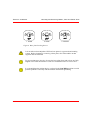
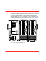
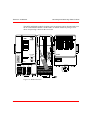
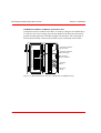
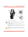
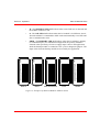
IndustrialIT
AC 800M and S800 I/O
Getting Started
IndustrialIT
AC 800M and S800 I/O
Getting Started
NOTICE
This document contains information about one or more ABB products and may include a
description of or a reference to one or more standards that may be generally relevant to
the ABB products. ABB may have one or more patents or pending patent applications
protecting the intellectual property in the ABB product(s) described in this publication.
The presence of any such description of a standard or reference to a standard is not a
representation that all of the ABB products referenced in this document support all of the
features of the described or referenced standard. In order to determine the specific features supported by a particular ABB product, the reader should consult the product specifications for the particular ABB product.
The information in this document is subject to change without notice and should not be
construed as a commitment by ABB. ABB assumes no responsibility for any errors that
may appear in this document.
In no event shall ABB be liable for direct, indirect, special, incidental or consequential
damages of any nature or kind arising from the use of this document, nor shall ABB be
liable for incidental or consequential damages arising from use of any software or hardware described in this document.
This document and parts thereof must not be reproduced or copied without written permission from ABB, and the contents thereof must not be imparted to a third party nor used
for any unauthorized purpose.
The software or hardware described in this document is furnished under a license and
may be used, copied, or disclosed only in accordance with the terms of such license.
This product meets the requirements specified in EMC Directive 89/336/EEC and in Low
Voltage Directive 72/23/EEC.
TRADEMARKS
All rights to copyrights, registered trademarks, and trademarks reside with their respective owners.
Copyright © 2003-2009 by ABB.
All rights reserved.
Release:
Document number:
March 2009
3BSE056248
TABLE OF CONTENTS
About This Book
General ..............................................................................................................................7
Document Conventions .....................................................................................................7
Warning, Caution, Information, and Tip Icons..................................................................7
Related Documentation .....................................................................................................8
Section 1 - Product Overview
Central Processing Unit (CPU) .......................................................................................10
Communication Interface ................................................................................................12
S800 I/O...........................................................................................................................12
Section 2 - Installation
Mounting AC 800M and S800 I/O Units onto DIN-Rail ................................................15
Mechanical Installation - Metal Sheet..................................................................15
Mechanical Installation - Prefabricated Aluminum Profile .................................17
Mounting and Removing PM8xx, CI8xx and S800L Units ............................................18
Mounting and Removing S800 I/O Units........................................................................20
Power Supply...................................................................................................................26
Section 3 - Configuration
Controller Configuration - Basic Rules and Examples ...................................................27
S800 I/O Configuration - Basic Rules and Examples .....................................................32
3BSE056248
5
Table of Contents
Section 4 - Operation
Hardware Indicators ........................................................................................................ 43
AC 800M Controller (PM8xx) ............................................................................ 43
LED Indicators..................................................................................................... 43
Switches and Push Buttons .................................................................................. 45
Communication Interface LEDs .......................................................................... 45
S800 I/O Module LEDs ....................................................................................... 46
S800L I/O Module LED ...................................................................................... 49
Start Modes ..................................................................................................................... 52
Section 5 - Maintenance/Replacement of
Faulty Units
Online Replacement of Unit............................................................................................ 53
Appendix A - IndustrialIT System 800xA
AC 800M Controller - Data Sheet ............................................................... 55
Appendix B - System 800xA S800 I/O System - Data Sheet ...... 59
Appendix C - Dimensions ............................................................................... 65
6
3BSE056248
About This Book
General
This manual is intended to give the reader a general knowledge about AC 800M,
S800 I/O and S800L hardware. It includes a general product overview, guidance for
installation, configuration examples, information valuable during operation and
maintenance considerations. Several other manuals forms the complete
documentation of AC 800M, S800 I/O and S800L hardware which are listed in the
subsection Related Documentation. However, this manual should give all needed
knowledge to get started with the use of the hardware.
Document Conventions
Microsoft Windows conventions are normally used for the standard presentation of
material when entering text, key sequences, prompts, messages, menu items, screen
elements, etc.
Warning, Caution, Information, and Tip Icons
This publication includes Warning, Caution, and Information where appropriate
to point out safety related or other important information. It also includes Tip to
point out useful hints to the reader. The corresponding symbols should be
interpreted as follows:
Electrical warning icon indicates the presence of a hazard which could result in
electrical shock.
Warning icon indicates the presence of a hazard which could result in personal
injury.
3BSE056248
7
Related Documentation
About This Book
Caution icon indicates important information or warning related to the concept
discussed in the text. It might indicate the presence of a hazard which could
result in corruption of software or damage to equipment/property.
Information icon alerts the reader to pertinent facts and conditions.
Tip icon indicates advice on, for example, how to design your project or how to
use a certain function
Although Warning hazards are related to personal injury, and Caution hazards are
associated with equipment or property damage, it should be understood that
operation of damaged equipment could, under certain operational conditions, result
in degraded process performance leading to personal injury or death. Therefore,
fully comply with all Warning and Caution notices.
Related Documentation
Document ID
8
Title
3BDS009029Rxxxx
IndustrialIT 800xA - Control and I/O, PROFIBUS DP, Wiring
and Installation
3BSE020923Rxxxx
IndustrialIT 800xA - Control and I/O, S800 I/O, General
Information and Installation
3BSE020924Rxxxx
IndustrialIT 800xA - Control and I/O, S800 I/O, Modules and
Termination Units
3BSE020927Rxxxx
IndustrialIT 800xA - Control and I/O, S800 I/O, Modules and
Termination Units with Intrinsic Safety Interface
3BSE036351Rxxxx
IndustrialIT 800xA - Control and I/O, AC 800M Controller
Hardware, Hardware and Operation
3BSE041880Rxxxx
IndustrialIT 800xA - Control and I/O, Getting Started,
Introduction and Basic Operation
3BSE056248
Section 1 Product Overview
The AC 800M controller consists of a selection of units mounted on horizontal
DIN-rails, which can be housed within an enclosure. The majority of units consist of
a base mounting plate and a removable module attached with screws.
The hardware units that form the AC 800 M controller are:
•
Central Processor unit (CPU)
•
Communication interface modules for different protocols
•
S800 I/O modules
•
Power supply modules
Figure 1. Example of an AC 800M Controller with an S800 I/O Unit
Various I/O systems can be connected to the AC 800M controller, either directly
(S800 I/O) or via PROFIBUS or FOUNDATION.
3BSE056248
9
Central Processing Unit (CPU)
Section 1 Product Overview
Central Processing Unit (CPU)
The CPU consist of a base plate TP830 (Terminal Plate) and a processor module
PM8XX with various speed and memory combinations.
The base plate TP830 carries the majority of the connections to processor, the power
supplies and communication interfaces, as well as to external buses.
Internal battery cover
Fuse
CEX-Bus
Socket
Modulebus
Socket
Power Supply
CPU
10
Base plate
3BSE056248
Section 1 Product Overview
LED
Status
Indicators
Central Processing Unit (CPU)
Compact Flash slot
INIT
Push button
CF Connector
RCU Link
Connector
(PM861/PM864/
PM865)
Tx/Rx
Optical ModuleBus
Electrical
ModuleBus
CEX-Bus
Tx/Rx
Status
Indicators
External Battery
Supply Socket
Power Supply
and
Supervision Signal
Socket (SS822/SS823)
CN1/CN2
Ports
DIN-rail
Locking Device
COM3/COM4
Ports
Lugs for extra screws to provide
secure mounting in locations subject
to vibration
Figure 2. Processor Unit - General View (here shown with PM861)
3BSE056248
11
Communication Interface
Section 1 Product Overview
Communication Interface
A number of communication modules can be connected to the controller. See
Appendix A, IndustrialIT System 800xA AC 800M Controller - Data Sheet for
more information on the various modules.
Communication Interface connected with CEX bus:
Up to 12 communication units can be placed on Communication Expansion Bus
(CEX) bus.
The CEX bus must be terminated if a communication unit is connected. A CEX bus
termination is delivered with the e CPU: tb850 (male) or TB851 (female).
An extension cable TK850 with connector DB25P with metal housing and a length
of 0.7meter (1.3') can be used for extending the CEX bus to a second din rail.
S800 I/O
S800 I/O is a distributed and modular I/O system that communicates with
controllers over PROFIBUS-DP/DPV1 or direct (via Modulebus).
The S800 I/O system is DIN rail mounted and consists of Fieldbus Communication
Interfaces, Modulebus Modems, S800 I/O modules and Module Termination Units
(MTU). S800 I/O modules (not S800L) are mounted on MTU's, this makes them
hot-swappable. Depended on the mounting requirement (horizontal or vertical) and
on the field termination needs (powering, fusing etc.) there are numerous of MTU's
to choose from.
The S800 I/O system supports fully redundant applications, redundancy can be built
in on both communication level and I/O module level.
S800 I/O connected with PROFIBUS- DP/DPV1:
12
•
Field Communication Interface CI801 or CI840 is the I/O station master
•
Maximum 24 I/O modules per I/O station
•
1 base I/O cluster with up to 12 I/O modules (connected via electrical
Modulebus)
•
1-7 additional I/O clusters with up to 12 I/O modules per cluster (connected via
optical Modulebus using Modulebus Modems)
3BSE056248
Section 1 Product Overview
S800 I/O
S800 I/O connected with Modulebus:
•
Connection via Electrical Modulebus (single controller only)
–
•
Up to 12 I/O modules
Connection via Optical Modulebus
–
1-7 I/O clusters with up to 12 I/O modules per cluster (connected using
Modulebus Modem TB820 or TB840A)
PM851 is restricted to one optical Modulebus cluster.
3BSE056248
13
S800 I/O
14
Section 1 Product Overview
3BSE056248
Section 2 Installation
Mounting AC 800M and S800 I/O Units onto DIN-Rail
AC 800M and S800 I/O units are DIN-rail mountable. Each unit has a DIN rail
locking mechanism that achieve mechanical locking and effective grounding.
The additional screw lugs, located in the lower part of the units are used to provide
extra fastening in environments subject to excessive vibrations. AC 800M units
(CPU and communication interfaces) must be mounted on horizontal DIN rails.
S800 I/O units can be mounted on both horizontal and vertical DIN rails.
There are two ways of mounting AC 800M and S800 I/O in cabinets, open rack or
other types of installations:
•
Mounting on DIN rail attached to a metal sheet
•
Mounting on prefabricated aluminium profile with DIN rail
All conductive structural components of the installation must be bonded together
with good and permanent connections for electrical safety and EMC reasons.
The bonding should preferably be made with self-tapping cutting head screws.
On painted surfaces where fastening is done by screw and nut, the paint must be
removed from the contact surfaces. Apply conductive grease on surfaces to ensure a
permanent connection. The cabinet/rack shall be properly connected to protective
earth/ground.
Mechanical Installation - Metal Sheet
The DIN-rail is mounted on an unpainted metal sheet with fastening screws every
100 mm to ensure good mechanical stability and a good chassis ground connection
in the cabinet or an open rack, see Figure 3.
3BSE056248
15
Mechanical Installation - Metal Sheet
Section 2 Installation
The metal sheet shall at least be 2.5 mm thick and at least 180 mm high with
preferably one side bend 90 degrees to increase the stability. The metal sheet shall
be mechanically fastened at least every 500 mm to the cabinet or rack with a
minimum of four screws. The fastening to the cabinet frame shall be performed with
self-tapping screws to get a good grounding connection.
DIN-rail type with height 7.5 mm shall be used. Refer to type NS 35/7.5 according
to standard EN50022.
For al l b olted join ts
Ensure goo d el ectri cal co nta ct to chassies
DIN-ra il 45 0 mm
70
100
10 0
100
1 00
D IN-ra il (he igh t 7, 5 mm) moun ted w it h
tap ping screws M6x1 0
Tap ping screws w ith scratche s M6x1 0
En d supp ort 2 x 3BSC02 24 71R1
178
266
Alte rnati ve ancho rin g
of exce ptio nal ca ble s.
Use ca ble sup por t bar
+ insul ating layer
+ str aps
Al tern ative an chori ng
of e.g . I/O cabl es in ap propria te ca ble du ct
Figure 3. Mechanical Installation
16
3BSE056248
Section 2 Installation
Mechanical Installation - Prefabricated Aluminum Profile
Figure 4. Cabinet with Controller and I/O on metal sheet
Mechanical Installation - Prefabricated Aluminum Profile
There are aluminum profiles for horizontal and vertical mounting. The aluminum
profile gives an excellent grounding and rigid mounting of products concerned.
The aluminum profile shall be fastened to the cabinet with at least 4 self-tapping
screws.
The profile has grooves for screws that can be used for fastening the modules in an
environment with excessive vibrations.
The aluminum profiles have one DIN-rail and one cable duct.
3BSE056248
17
Mounting and Removing PM8xx, CI8xx and S800L Units
Section 2 Installation
The aluminum profiles are available in different sizes. For horizontal mounting use
3BSE022255R1 (465 mm, 19") or 3BSE022256R1 (592 mm, 24") or
3BSE022257R1 719 mm, 28.31"). For vertical mounting use 3BSE049768R1 (1800
mm, 71").
Figure 5. Cabinet with Controller on prefabricated aluminium profiles
Mounting and Removing PM8xx, CI8xx and S800L Units
Before mounting any processor unit or communication interface onto the DIN-rail,
read carefully the installation instructions provided with the equipment. Since the
electronic unit and base plate are supplied as a single unit, there is no requirement to
separate them during the mounting procedure.
Mounting the units onto the DIN-rail only requires a blade screwdriver that fits
securely into the locking screw (1 mm slot).
18
3BSE056248
Section 2 Installation
1 . OPEN
Mounting and Removing PM8xx, CI8xx and S800L Units
2. SLIDE
3. LOCKED
Figure 6. Base plate Locking Device
It is not allowed to manipulate CEX bus base plates in a powered and running
system. Before changing or removing a base plate, all CEX modules on that
segment must be removed.
To prevent damage to the pins, be sure the base plate plugs and sockets are fully
aligned as the units interconnect. Under no circumstances use excessive force.
It is essential that the locking device is placed in the LOCKED position to avoid
possible problems caused by vibration and/or intermittent grounding.
3BSE056248
19
Mounting and Removing S800 I/O Units
Section 2 Installation
When disconnecting units from each other, use a screw driver according to Figure 7
F
R
Rx1
F
R
Rx/Tx
Tx1
RTS
F
R
P
B
Rx2
Tx2
INIT
CI851
CI853
COM1
COM2
PM860
CN1
CN2 COM3 COM4
Figure 7. Separating the Base Plates
Mounting and Removing S800 I/O Units
The S800 I/O is mounted on a standard DIN-rail according to EN 50022 NS35/7,5.
The DIN-rail is mounted in a cabinet or on an enclosure wall to a metal sheet with
fastening screws every 100 mm to ensure a good chassis ground connection in the
cabinet or an open rack. The ModuleBus master, ModuleBus Modem, MTUs and
S800L I/O modules are mounted to the DIN rail. In environments with major
vibrations, the MTUs shall also be screwed on the metal sheet. The FCI, ModuleBus
Modem and MTUs have a snap locking device that attaches it to the mounting rail.
It is possible to mount the FCI, ModuleBus Modem, MTUs and S800L I/O modules
both vertically and horizontally.
20
3BSE056248
Section 2 Installation
Mounting and Removing S800 I/O Units
To mount the FCI, ModuleBus Modem or MTU, place it on the top edge of the
DIN rail, release the rail latch with a flat blade screw driver and snap the bottom
mechanism into place. When the unit is in place on the DIN rail and in position, take
away the screw driver and the rail latch will fix the unit in position on the DIN rail.
Release the unit from the DIN rail in a similar way.
A flat blade screw driver can be used to release the latch to allow easier movement
along the DIN rail or removal of the unit (Figure 8).
DIN-rail
I/O Module
Lock/Switch
To
E
F
Lock
D
A
E
F
B
C
Ground
Clip Spring
A
D
B
C
L1+ C1 2
Move up to
release rail
latch
L1+ B1 2
L1- A1 2
3
3
4
4
3
5
5
4
6
6
5
7
7
6
C8 L2+
B8 L2+
7
A8 L2-
Pry down to
release rail
latch
Figure 8. MTU Latching System
3BSE056248
21
Mounting and Removing S800 I/O Units
Section 2 Installation
Snapping the FCI, ModuleBus Modem or MTU to the DIN-rail makes contact by a
grounding spring with the chassis.
Connection of the MTU, or S800L module, ModuleBus connector to the FCI,
ModuleBus Modem, next MTU or S800L module is made by sliding the MTU or
the S800L module along the mounting rail and then locking it in place (Figure 9).
F
R
T1
T2
D
D
E
F
E
F
D
A
B
C
D
AF100
1
A
B
C
SWX.X/Y
L+ L+ SA
L- L- SB
A
B
C
STN. ADDR.
4 56
3
7 x 10
2
8
109
4 56
3
7 x1
2
8
109
CI810
A
B
C
SERVICE
E
F
E
F
P
Tx Rx
2
+
+
-
-
SH
SH
SH
SH
Tx
L1+ C1 2
L1+ B1 2
3
3
4
4
5
5
6
6
7
7
C8 L2+
B8 L2+
L1+ C1 2
L1+ B1 2
3
3
4
4
5
5
6
6
7
7
C8 L2+
B8 L2+
Rx
L1- A1 2
3
4
5
6
7
A8 L2-
L1- A1 2
3
4
5
6
7
A8 L2-
Figure 9. I/O Station Installation Diagram
22
3BSE056248
Section 2 Installation
Mounting and Removing S800 I/O Units
The MTU and S800L module (locking screw in position) can be disconnected from
the FCI, ModuleBus Modem, another MTU or S800L module by using a screw
driver and pressing it between the two items.
F
R
T1
T2
E
F
P
D
D
AF100
1
A
B
C
SWX.X/Y
L+ L+ SA
L- L- SB
DO801
E
F
STN. ADDR.
4 56
3
7 x 10
2
8
109
4 56
3
7x1
2
8
109
CI810
A
B
C
SERVICE
Tx Rx
2
+
+
-
-
SH
SH
SH
Tx
L1+ C1 2
L1+ B1
SH
2
3
3
5 6 7
4
4
5
6
C8 L2+
B8 L2+
7
Rx
L1- A1
2
3
4
5
6
7
A8 L2-
Figure 10. Module Release
3BSE056248
23
Mounting and Removing S800 I/O Units
Section 2 Installation
I/O Module Installation on Module Termination Unit
Connection of the I/O module to the MTU is made by setting the I/O Module Keys
#1 and #2 to the correct setting, place the I/O Module Lock/Switch to the unlock
position and then push the I/O module straight onto the MTU. The I/O module is
locked and electrically connected to the MTU by the I/O Module Lock/Switch.
F
R
W
I/O Module Lock/Switch
(shown unlocked)
E
F
E
F
Turn clockwise
to lock I/O Module
D
E
F
D
D
E
F
I/O Module
Key #1
A
B
C
A
D
B
C
DI810
24V
A
B
C
A
B
C
1
2
3
4
5
6
7
8
9
10
11
12
13
14
15
16
I/O Module Lock/Switch
(shown locked)
I/O Module
Key #2
Figure 11. MTU Mechanical Keys for I/O Module and Module Lock
24
3BSE056248
Section 2 Installation
Mounting and Removing S800 I/O Units
Figure 12. Mounting of I/O module on MTU
At the mounting of a S800 I/O Box on a Termination Unit the following should
be observed:
Press the Box straight and right on to stop into the Termination Unit. Above
shown angle shall be 0°.
Turn the Locking Device clockwise to its end position. Above shown state with
the Locking Device in a position before end position shall not exist for an active
module.
Do not turn the I/O Module Lock/Switch counter-clockwise from the unlocked
position. This will cause it to break and will make the MTU and the I/O module
inoperative.
3BSE056248
25
Power Supply
Section 2 Installation
Power Supply
It is recommended to feed the system components and field equipment from
different power supplies. Example of system components are Controllers,
Communication Modules, Fieldbus Communication Interfaces and Modulebus
Modems, (for instance PM864A, CI854A, CI840A and TB840A). Example of field
equipment is transmitters, actuator as well as the field side of the S800 I/O modules
(terminals on MTU and S800L marked L+ and L-).
The power supplies can also be configured in a redundant configuration using
independent voting units.
Figure 13. Recommended Power Supply Concept
26
3BSE056248
Section 3 Configuration
Controller Configuration - Basic Rules and Examples
Information regarding limitations for the different controllers can be found in
IndustrialIT 800xA - Control and I/O, AC 800M Controller Hardware, Hardware
and Operation (3BSE036351Rxxxx).
3BSE056248
27
Controller Configuration - Basic Rules and Examples
Section 3 Configuration
Single CPU Configuration
28
3BSE056248
Section 3 Configuration
Controller Configuration - Basic Rules and Examples
Single CPU with Redundant CI Configuration
3BSE056248
29
Controller Configuration - Basic Rules and Examples
Section 3 Configuration
Redundant CPU with Non-Redundant CI Configuration
30
3BSE056248
Section 3 Configuration
Controller Configuration - Basic Rules and Examples
Redundant CPU with Redundant CI Configuration
3BSE056248
31
S800 I/O Configuration - Basic Rules and Examples
Section 3 Configuration
S800 I/O Configuration - Basic Rules and Examples
Information regarding limitations for the different I/O modules can be found in
IndustrialIT, Control and I/O, S800 I/O, General Information and Installation
(3BSE020923Rxxxx).
32
3BSE056248
Section 3 Configuration
S800 I/O Configuration - Basic Rules and Examples
Non-redundant PROFIBUS Node
In total max 24 modules per CI801 but limited by:
•
PROFIBUS data capability.
•
CI801/TB820 Power supply capability.
•
Required scan cycle time.
Modules not supported:
DI825, DO880, AI880A, DI830, DI831, DI880, DI885.
5 Mbit/s ABB Drives and SOE on DI840 are not supported.
3BSE056248
33
S800 I/O Configuration - Basic Rules and Examples
Section 3 Configuration
Line/Master-redundant PROFIBUS Node
In total max 24 modules per CI840A but limited by:
•
PROFIBUS data capability.
•
CI840A/TB820 Power supply capability.
•
Required scan cycle time.
Modules not supported:
DI825, DO880, AI880A, DI830, DI831, DI880, DI885.
ABB Drives and SOE on DI840 are not supported.
34
3BSE056248
Section 3 Configuration
S800 I/O Configuration - Basic Rules and Examples
Line/Master-redundant PROFIBUS Node with Redundant I/O
In total max 24 modules per CI840A (a redundant pair is 2 modules) but limited by:
•
PROFIBUS data capability.
•
CI840A/TB820 Power supply capability.
•
Required scan cycle time.
Modules not supported:
DI825, DO880, AI880A, DI830, DI831, DI880, DI885.
ABB Drives and SOE on DI840 are not supported.
3BSE056248
35
S800 I/O Configuration - Basic Rules and Examples
Section 3 Configuration
Direct I/O to non-redundant AC 800M Controller
In total max 96 modules but limited by:
•
PM8xx and TB820 Power supply capability.
•
Required scan cycle time.
•
Required CPU load.
Supported modules:
DI880, DO880, AI880A are supported if PM865 and TB840A (instead of TB820).
The optical ModuleBus can be configured for long distances and in star configurations using
TB825 see Long distance distribution in star as Direct I/O to AC 800M on page 42.
36
3BSE056248
Section 3 Configuration
S800 I/O Configuration - Basic Rules and Examples
Direct I/O to redundant AC 800M Controllers
In total max 84 modules but limited by:
•
TB840A Power supply capability.
•
Required scan cycle time.
•
Required CPU load.
Supported modules:
AI880A, DI880, DO880 are supported if PM865.
The optical ModuleBus can be configured for long distances and in star configurations using
TB825 see Long distance distribution in star as Direct I/O to AC 800M on page 42.
3BSE056248
37
S800 I/O Configuration - Basic Rules and Examples
Section 3 Configuration
Direct redundant I/O to redundant AC 800M Controllers
In total max 42 pairs of modules but limited by:
•
TB840A Power supply capability.
•
Required scan cycle time.
•
Required CPU load.
Supported redundant modules:
DI840, DO840, AI843, AO845, DP840, AI845. AI880A, DI880, DI880 are supported if
PM865. The optical ModuleBus can be configured for long distances and in star
configurations using TB825 see Long distance distribution in star as Direct I/O to AC 800M
on page 42. It is possible to mix clusters with and without redundant I/O, but not on the same
cluster. See non-redundant I/O for information.
38
3BSE056248
Section 3 Configuration
S800 I/O Configuration - Basic Rules and Examples
High Integrity I/O to non-redundant High Integrity Controller
In total max 96 modules but limited by:
•
PM8XX and TB840A Power supply capability.
•
Required scan cycle time.
•
Required CPU load.
The optical ModuleBus can be configured for long distances and in star configurations using
TB825 see Long distance distribution in star as Direct I/O to AC 800M on page 42.
3BSE056248
39
S800 I/O Configuration - Basic Rules and Examples
Section 3 Configuration
High Integrity I/O to redundant High Integrity Controllers
In total max 84 modules but limited by:
•
TB840A Power supply capability.
•
Required scan cycle time.
•
Required CPU load.
The optical ModuleBus can be configured for long distances and in star configurations using
TB825 see Long distance distribution in star as Direct I/O to AC 800M on page 42.
NOTE! In a configuration with redundant CPUs, COM3 and the electrical ModuleBus
cannot be used.
40
3BSE056248
Section 3 Configuration
S800 I/O Configuration - Basic Rules and Examples
HI redundant or hot replacement I/O to redundant PM865
In total max 42 pairs of modules but limited by:
•
TB840A Power supply capability.
•
Required scan cycle time.
•
Required CPU load.
Supported modules:
DI840, DO840, AI843, AO845, DP840, DI880, DO880, AI845, AI880A. The optical
ModuleBus can be configured for long distances and in star configurations using TB825 see
Long distance distribution in star as Direct I/O to AC 800M on page 42. It is possible to mix
clusters with and without redundant I/O but not on the same cluster. See non-redundant I/O
for information.
3BSE056248
41
S800 I/O Configuration - Basic Rules and Examples
Section 3 Configuration
Long distance distribution in star as Direct I/O to AC 800M
Calculation of the ModuleBus delay for the configuration in the figure above:
ModuleBus delay = (total delay in optical fiber) + 5 x (opto-to-opto delay in TB820) + 2 x
(delay in TB825) + (opto-to electrical delay in TB820) = (4 x 15 + 3 x 1.5 + 1000) x 0.01 +
5 x 4 + 2 x 2.4 + 6.5 = 42 s.
42
3BSE056248
Section 4 Operation
Hardware Indicators
AC 800M Controller (PM8xx)
Equipped with Control Software, the basic PM8xx/TP830 hardware units mounted
on the AC 800M hardware platform constitute an AC 800M Controller.
LED Indicators
See Figure 2, for description of placement.
Table 1. PM8xx - LED Indicators
Marking
Color
Function
F(ault)
Red
Normal state - OFF
Re-start (INIT) temporarily lit F(ault).
May also be operated by software program
R(un)
R(un)
Normal state - ON
Re-start (INIT) temporarily extinguishes R(un). At restart press the (INIT)
push button (3 sec. or more) until R(un) flashes.
May also be operated by software program.
P(ower)
Green
Normal state - ON
When lit, indicates that the CPU DC/DC converter is generating valid +5
V and +3.3 V DC supply voltages.
No software control.
3BSE056248
43
LED Indicators
Section 4 Operation
Table 1. PM8xx - LED Indicators (Continued)
Marking
Color
Function
B(attery)
Green
Normal state - ON
Lit when internal or external battery voltage is above 3.1 V. The LED is
controlled by a software battery voltage test(1).
Tx
Yellow
Data Transmission(2),
CN1 + CN2 and COM3 + COM4
Flashes in synchronization with Tx traffic
Rx
Yellow
Data Reception(2), CN1 + CN2 and COM3 + COM4
Flashes in synchronization with Rx traffic
Valid for PM8xx in redundant operation
PRIM(ary
Yellow
Lit in single and redundant configuration.
Indicates Primary CPU in redundant configuration. Controlled by
software.
DUAL
Yellow
Lit when the CPU is running in redundant configuration and
synchronized state.s
(1) The software performs cyclic battery voltage level tests via a dedicated LED control input. The battery provides
back-up power for both the application memory and the real time clock during power down. The battery is either
accessible via the PM8xx cover panel or externally connected to the external battery connector. Battery voltage is
checked by the software. Voltage is common for both the internal and external battery. For this reason the internal
battery should be removed when using the external battery, since having two batteries connected in parallel will
result in greatly reduced capacity.
(2) Only CN1 for PM851. Do not connect to CN2
44
3BSE056248
Section 4 Operation
Switches and Push Buttons
Switches and Push Buttons
Table 2. PM8xx - Switches and Push Buttons
Marking
INIT
Color
Function
Manual
Push
Button
Initiates
1. Cold Restart if INIT is held less than 2.5 seconds.
2. Controller Reset if INIT is held more than 3 seconds.
If INIT is pushed on the Primary CPU in redundant configuration a switch
over to the backup CPU will be initiated.
Communication Interface LEDs
Table 3 and Table 5 shows Indicators for the communication interface modules.
Table 3. Common LEDs for Communication Interfaces
Marking
Color
Description
F(Fault)
Red
Unit error detected
R(Run)
Green
Operating
Tx/Tx1/Tx2 (Transmit)
Yellow
Flashes if transmitting
Rx/Rx1/Rx2/RxA/RxB (Receive)
Yellow
Flashes if receiving
RxTx (Receive &Transmit)
Yellow
Flashes if transmitting or receiving
3BSE056248
45
S800 I/O Module LEDs
Section 4 Operation
Table 4. Common LEDs for Communication Interfaces in Redundant operation
Marking
Color
Description
PRIM(Primary)
Yellow
Indicates the primary unit in redundant
configuration. (LED is on in both single and
redundant configuration).
DUAL
Yellow
Indicates when unit is running in redundant
configuration.
Table 5. Special LEDs
Module
Marking
Color
Description
CI858
Tools
Yellow
Indicates reception / transmission of data frames
on the PC Tool buss.
CI862
Com Error
Yellow
Indicates traffic.
CI856
TO
Yellow
Flashes at S100 I/O access time-outs.
S800 I/O Module LEDs
Figure 14 shows examples of front panels for different types of I/O modules. On the
front of all I/O modules there are at least three LEDs (FAULT, RUN and
WARNING) indicating the module status. Additionally some modules have LEDs
indicating OSP or PRIMARY. Each digital channel also has one LED indicating
current state (on/off). For more information see the tables below.
46
•
F - The FAULT LED shall indicate when the I/O module detect a fatal error or
before first access after power up.
•
R - The RUN LED shall indicate when the I/O module is operational.
3BSE056248
Section 4 Operation
S800 I/O Module LEDs
•
W - The WARNING LED shall indicate when a non-fatal error is detected and
the module continues to run.
•
O - The OSP LED shall indicate when the I/O module is in OSP state, that is,
when the module is commanded to OSP or when automatically set to OSP state
due to communication error.
•
PRIM - The PRIMARY LED shall indicate when the I/O module is primary
(in a redundant pair). In a redundant configuration, the primary module is
scanned at the specified cycle time to supply input values to the application,
while the backup module is scanned at a low cycle for diagnostic purpose. The
input values from the backup module are not used by the application.
F
R
W
O
1
2
3
4
5
6
7
8
9
10
11
12
13
14
15
16
F
R
W
F
R
W
O
F
R
W
F
R
W
O
PX1
UP1
ST1
DI1
SY1
DO1
TP1
UL1
PX2
UP2
ST2
DI2
SY2
DO2
TP2
UL2
1
2
3
4
5
6
7
8
9
10
11
12
13
14
15
16
DO810
DI810
AO810/AO810V2
AI810
DP820
Figure 14. Examples of S800 I/O Modules LED Locations
3BSE056248
47
S800 I/O Module LEDs
Marking
Section 4 Operation
Color
Description
F (Fault)
Red
Internal fault in the module affecting all channels(1)
R (Run)
Green
Operational state
W (Warning)
Yellow
External fault or internal channel error
O (OSP)
Yellow
OSP state (Outputs Set as Predetermined)
P (Primary
Yellow
LED indicating that the module is operating as primary in a
redundant pair
Channel status
Yellow (+red)
This LED shows both value (Yellow ON/OFF) and error (red)
(1) Modules without self test function: The F-LED will switch on at power up or restart of the module and switch off after
the first successful access to the module. Modules with self test function: The F-LED will switch on at power up,
restart of the module or when the module goes to Error state. If the module has not gone to Error state it will switch
off the F-LED after the first successful access to the module.
Module State
Run
Fault
Warning
OSP
Primary
Channel Status
Off
Off
Off
DI On/Off(1), DO Off
Not configured Flashing/Off On/Off(2)
On/Off
Off
Off
DI On/Off(1), DO Off
Ready
Flashing/Off Off
On/Off
Off
Off
DI On/Off, DO Off
Operational
On
Off
On/Off
Off
On/Off
On/Off
OSP
On
Off
On/Off
Off
On/Off
On/Off
Error
Off
On
On/Off
Off
Off
DI On/Off, DO Off
Init
Off
On
(1) The DI signal status for module DI830, DI831, DI880, DI885, DP820 is only OFF0.
(2) Will be switched off after the first successful access to the module.
48
3BSE056248
Section 4 Operation
S800L I/O Module LED
S800L I/O Module LED
Figure 15 shows examples of front panels for different types of I/O modules. On the
front of each I/O module there is one LED indicating the module status. See the
tables below for information on the meaning and indications for these modules.
For modules with special LED indications see respectively module in Appendix A,
IndustrialIT System 800xA AC 800M Controller - Data Sheet.
The LED shall indicate:
•
Red when the I/O module detect a fatal error or before first access after power
up.
•
Green when the I/O module is operational.
Each digital channel has one LED indicating current state (on/off).
3BSE056248
49
S800L I/O Module LED
Section 4 Operation
S 1 2 3 4 5 6 7 8 9 10 1112 13 14 15 16
STATUS
STATUS
S
AI801
0(4)...20 mA
DO801
24 V 0.5 A
L+ L- 24 V
L+ L- 24 V
+
1
I
+
2
I
3
+
4
I
+
I
+
5
I
+
6
I
+
7
I
+
8
I
1 2 3 4 5 6 7 8 9 10 11 12 13 14 15 16
Figure 15. Example of S800L I/O Module LED Locations
50
3BSE056248
Section 4 Operation
Marking
S(Status)
S800L I/O Module LED
Color
Description
Red
Fault in the module(1)
Green
Operational state
(1) Modules without self test function, for example, DI/DO modules: The S-LED will switch on to red at power up or
restart of the module and switch off after the first successful access to the module. Modules with self test function for
example, AI/AO modules: The S-LED will switch on to red at power up, restart of the module or when the module
goes to Error state. If the module has not gone to Error state it will switch off the S-LED after the first successful
access to the module.
Module State
Init
Status
Red
Channel Status
Off
Not configured Red/Off(1)
Off
Ready
Off
DI On/Off, DO Off
Operational
Green
On/Off
OSP
Green
On/Off
Error
Red
DI On/Off, DO Off
(1) Will be switched off after the first successful access to the module.
3BSE056248
51
Start Modes
Section 4 Operation
Start Modes
The controller may be started with the following start modes:
Warm init
•
Power Off / On with a battery backed up CPU.
•
Applications restart with retain values.
Cold init
•
Press init <2.5 s.
•
Applications restart with cold retain values.
Reset
52
•
Press init >3 s or until RUN lead flashes.
•
Applications are deleted in controller.
3BSE056248
Section 5 Maintenance/Replacement of
Faulty Units
Online Replacement of Unit
Replacement online entails adding or removing units in a controller without
disturbing the execution of the running application program. Units are connected to
the CEX-Bus and the electrical ModuleBus (S800 I/O).
CEX-Bus
Communication interfaces ()
Can be removed or replaced online
Restrictions apply; refer to the installation section
for each interface.
Base plates for CI8xx (TP8xx)
It is not allowed to manipulate CEX bus base
plates in a powered and running system. Before
changing or removing a base plate, all CEX
modules on that segment must be removed.
ModuleBus
S800 I/O units
Can be removed or replaced online. (Not S800L)
Module Terminal Units (MTUs)
Must not be replaced online
Redundant CPUs
Processor unit
3BSE056248
Can be removed or replaced online by following a
specified sequence (see the next following pages)
53
Online Replacement of Unit
54
Section 5 Maintenance/Replacement of Faulty Units
3BSE056248
PM851
PM856
PM860
PM861A
PM864A
PM865
PM866
CPUs/Features
Appendix A IndustrialIT System 800xA
AC 800M Controller - Data Sheet
PM851K01
incl: 1
PM851
CPU and
required
optional
items
PM856K01
incl: 1
PM856
CPU and
required
optional
items
PM860K01
incl: 1
PM860
CPU and
required
optional
items
PM861AK0
1 incl: 1
PM861A
CPU and
required
optional
items
PM861AK0
2 incl: 2
PM861A
CPUs and
required
optional
items
PM864AK0
1 incl: 1
PM864A
CPU and
required
optional
items
PM864AK0
2 incl: 2
PM864A
CPUs and
required
optional
items
PM865AK0
1 incl: 1
PM864A
CPU and
required
optional
items
PM864AK0
2 incl: 2
PM864A
CPUs and
required
optional
items
PM866AK0
1 incl: 1
PM864A
CPU and
required
optional
items
PM864AK0
2 incl: 2
PM864A
CPUs and
required
optional
items
High Integrity No
Controller
No
No
No
No
Yes
No
Clock
frequency
48 MHz
Processor
unit
3BSE056248
48 MHz
together
with SM81x
48 MHz
48 MHz
96 MHz
96 MHz
133 MGHz
55
PM864A
PM865
PM866
8 Mb
8 Mb
16 Mb
32 Mb
32 Mb
64 Mb
CPU
redundancy
support
No
No
No
Yes
Yes
Yes
Yes
Performance
Relation
1.0 ms
1.0 ms
2.0 ms
2.0 ms
3.1 ms
3.1 ms
4.3 ms
12
12
12
PM860
8 Mb
PM856
Memory
(RAM)
PM851
PM861A
CPUs/Features
Appendix A IndustrialIT System 800xA AC 800M Controller - Data Sheet
Down to 1 ms
Cycle time
per
application
programs
Comm.
modules on
CEX bus
1
I/O capacity
on
ModuleBus
modules
modules
modules
modules
modules
modules
modules
max 24 I/O max 96 I/O max 96 I/O max 96 I/O max 96 I/O max 96 I/O max 96 I/O
Ethernet
channels for
Control
Network
1
Dimensions
56
12
2
12
2
12
(84 in
redundant
configuration)
(84 in
redundant
configuration)
(84 in
redundant
configuration)
(84 in
redundant
configuration)
2
2
2
2
W 119 x H 186 x D 135 mm (4.7 x 7.3 x 5.3 in.)
3BSE056248
Module
Protocol
Master or
slave
CI854A CI860
DP-V1
HSE
(PA via
Linking
Device)
(H1 via
Linking
Device)
CI853
1
CI855
2
CI858
CI856
CI862
CI865
CI867
Drivebus
S100
I/O
Trio I/O Satt I/O Modbus
TCP
IEC 61850
Modbus TCP
Satt I/O
TRIO I/O
S100 I/O interface
Drivebus
INSUM
CI857
Modbus MB300 IEEE
802.3
master,
Comlimaster/
slave,
Siemens
master,
User
defined
protocol
s
master master master/
slave
Number of 1
channels
MB300
RS-232 C
Foundation Fieldbus
PROFIBUS
Supported
Communication modules
Appendix A IndustrialIT System 800xA AC 800M Controller - Data Sheet
CI868
IEC
61850
master/ master master master master master master/ n/a
slave
slave
2
1
1 main, 1
2 aux
1
1
1 10/100
Mbps
1
1 10
Mbps
Max units
on CEX
bus
12
6
12
12
6
2
12
4
4
12
4
Cable
redundancy
yes
no
no
yes
no
no
no
no
no
no
no
3BSE056248
57
Module
redundancy
Dimensions
58
yes
yes
no
no
no
no
no
no
no
yes
IEC 61850
Modbus TCP
Satt I/O
TRIO I/O
S100 I/O interface
Drivebus
INSUM
MB300
RS-232 C
Foundation Fieldbus
PROFIBUS
Supported
Communication modules
Appendix A IndustrialIT System 800xA AC 800M Controller - Data Sheet
no
W 58 x H 186 x D 135 mm (2.3 x 7.3 x 5.3 in.)
3BSE056248
Appendix B System 800xA S800 I/O System Data Sheet
General specifications
Power supply
24V d.c. (19.2 - 30V)
Temperature range
0...55°C (non-condensing)(1)
Protection class
IP20
Standards complied with:
- Electrical safety
EN 3810, EN 50178, IEC 61131-2, UL508,
CSA 22.2 No. 142-M1987
- Hazardous locations (Class1 Zone 2
and Class 1 Division 2)
No. 213-M1987, FM 3600, FM 3611, UL 60079-15,
CSA 22.2 No.213-M1987 CAN/CSA-E60079-15:02
- Corrosive gases
ISA Class G2 or G3 (ISA-71.04)
Insulation test voltage
500/2000V a.c.
Communication media
Profibus DP
Twisted pair screened/fiber-optic cable. Up to 99
stations per bus. Up to 32 per twisted-pair segment.
Bus length: Up to 1200m (3937ft.) per twisted-pair
segment.
Communication interfaces
CI801
3BSE056248
For PROFIBUD-DP/V1. Hot Configuration In Run &
HART® pass-through. GSD-file provided.
59
Appendix B System 800xA S800 I/O System - Data Sheet
TB820/825/842
Optical cluster modem/ports for ModuleBus/drives
integration.
CI840A
For redundant PROFIBUS-DP/V1. Hot Configuration
in Run & HART® pass through. GSD file provided.
TB840A
Optical cluster modem for redundant or single
ModuleBus.
Installed on TU807/TU840/TU841/TU848/TU849.
Used with AC 800M.
Module Termination Units (MTU:s)
Compact, 50V applications
TU810
With screw terminals.
TU812
With 25 pin D-sub connector.
TU814
With 3 crimp snap-in connectors.
Compact, 250V applications
TU811
With screw terminals.
TU813
With 3 crimp snap-in connectors.
Compact for intrinsic safety
TU89X
With screw terminals & isolated power supply.
Extended, 50V applications
TU830/TU835/TU838/TU850
With screw terminal, pwr. distribution & fuse.
TU833
With spring-cage term., pwr distribution & fuse.
TU834
With screw terminals for shunt sticks.
Extended, 250V applications
TU831/TU836/TU837/TU839
With screw terminals, pwr. distribution & fuse.
Redundancy, 50V applications
TU842/843
(horiz./vert. mounting) With screw terminals.
TU844/845
(horiz./vert. mounting) With screw terminals and
shunt stick, TY80X.
Terminal Unit
TU805
For DI801 & DO801. With field power distribution
screw terminals.
60
3BSE056248
Appendix B System 800xA S800 I/O System - Data Sheet
S800 I/O modules
Digital input modules
DI810
16 channels, 2 groups of 8 ch., 24V d.c., current sink.
DI811
16 channels, 2 groups of 8 ch., 48V d.c., current sink.
DI814
16 channels, 2 groups of 8 ch., 48V d.c., current
source.
DI820
8 channels, separate returns, 110V d.c., 120V a.c.
DI821
8 channels, separate returns, 220V d.c., 230V a.c.
DI825
With time tagging. 8 channels, sep. returns, 125V d.c.
DI830
With time tagging. 16 channels, 2 groups of 8
channels, 24V d.c., current sink. Resolution: <0.5ms.
DI831
With time tagging. 16 channels, 2 groups of 8
channels, 48V d.c., current sink. Resolution: <0.5ms.
DI885
With time tagging. 8 channels, common return,
24-48V d.c. current sink. Time tagging resolution:
1ms.
Pulse input module
DP820
2 channels, separate returns, 0.25Hz -1.5MHz, signal
voltage: 5 / 24V d.c.
Digital output modules
DO810
16 channels, 2 groups of 8 channels, 24V, max 0.5A
d.c., transistor, current source, short-circuit-proof.
DO814
16 channels, 2 groups of 8 channels, 24V d.c., max
0.5A, transistor, current sink, short-circuit-proof.
DO815
8 channels, 2 groups of 4 channels, 24V d.c., max
2A, transistor, current source, short-circuit-proof.
DO820
8 channels, separate returns, 5-250V, max 3A
a.c./d.c., relay (N.O.).
3BSE056248
61
Appendix B System 800xA S800 I/O System - Data Sheet
DO821
8 channels, separate returns, 5-250V, max 3A
a.c./d.c., relay (N.C.).
Analog input modules
AI810
8 channels, single-ended, 0(4)-20mA, 0(2)-10V,
12bits.
AI815
8 channels, common return, 0(4)-20mA, 0(1)-5V,
HART
AI820
Differential inputs, 4 channels, 0(1)-5V, ±0(2)-10V,
±0(4)-20mA, 14 bits+sign.
AI825
Galvanically isolated, 4channels, ±0(2)-10V, ±0(4)20mA, 14 bits+sign.
AI830A
RTD inputs, 8 channels Pt100, Ni100, Ni120, Cu10,
resistor 0-400Ω, 14 bits, 3-wire.
AI835A
TC inputs, 8 channels, (7+ ref. junction), separate
returns, TC types B, C, D, E, J, K, L, N, R, S, T, U,
-30...75mV, 15 bits.
Analog output modules
AO810V2
8 channels, common return, 0(4)-20mA, 14 bits,
load: 850Ω (short-circuit-proof).
AO815
8 channels, common return, 4-20mA, HART
AO820
Isolated output, 4 channels, separate returns,
measuring range: ±0(2)-10V, ±0(4)-20mA,
resolution:12 bits + sign, load: ≤500Ω (current) ≥2kΩ
(voltage), short-circuit-proof.
S800 I/O modules for redundancy & SIL3
DI840
16 channels, common return, 24V d.c., current sink,
extended diagnostics.
DI880
16 channels, 24V d.c., current sink, SIL3, extended
diagnostics.
DP840
8 channels, separate returns, freq. measurement or
pulse counting, 0.5-20kHz, 12/24V d.c. or NAMUR.
62
3BSE056248
Appendix B System 800xA S800 I/O System - Data Sheet
DO840
16 channels, common return, 24V d.c., max 0,5A,
current source, short-circuit-proof, extended
diagnostics.
DO880
16 channels, 24V d.c., max. 0.5A, current source,
SIL3, short-circuit-proof, extended diagnostics.
AI843
TC input, 8 channels + ref. junction, TC types: B, C,
E, J, K, L, N,R, S, T, U, -30...75mV, 16 bits, extended
diagnostics.
AI845
8 channels, common return, 0(4)-20mA 0(1)-5V,
extended diagnostics, HART support.
AI880A
8 channels, common return, 0(4)-20mA, SIL3,
extended diagnostics, HART support.
AO845A
8 channels, common return, 4.20mA, extended
diagnostics, HART support.
S800L I/O modules
DI801
16 channels, 1 group, 24V d.c., current sink.
DI802
8 channels, 110V d.c., 120V a.c.
DI803
8 channels, 220V d.c., 230V a.c.
DO801
16 channels, common return, 24V, max 0.5A d.c.,
transistor, current source, short-circuit-proof.
DO802
8 channels, 5-250V, max 2A a.c./d.c., relay (N.O).
AI801
8 channels, single-ended, 0(4)-20mA, 12 bits.
AO801
8 channels, common return, 0(4)-20mA, 12 bits, load:
<750Ω.
I/O modules with intrinsic-safety interface
DI890
8 channels, separate returns, 24V d.c. current sink,
with wire-fault detection
DO890
4 channels, separate returns, load 150-5000Ω, 11V
@ 40mA, current source, short-circuit-proof, with
wire-fault detection.
3BSE056248
63
Appendix B System 800xA S800 I/O System - Data Sheet
AI890
8 channels, single-ended, 0(4)-20mA, 12 bits,
transmitter power supply.
AI893
8 channels, TV 7 + ref. junction, separate returns,
TC types B, C, E, J, K, L, N, R, S, T, U, -10...80mV,
RTD: Pt50-1000, Ni100-500, Cu10-100, resistor 04000Ω, 3-wire, 15 bits + sign., TC/RTD inputs.
AI895
8 channels, single-ended, 4-20mA, 12 bits,
transmitter power supply, HART interface.
AO895
8 channels common return, 0(4)-20mA, 12 bits,
load: 750Ω (short-circuit-proof), wire-fault detection
AO895
8 channels, common return, 4-20mA, 12 bits,
load: 750Ω (short-circuit-proof), HART interface &
wire-fault detection.
(1) Approvals are issued for +5 to +55°C.
64
3BSE056248
Appendix C Dimensions
Redundant Comm. Modules
Extended I/O
Intrinsic safety I/O
Compact I/O
Redundant I/O
Communication Interface
CPU
3BSE056248
CI801, S800L I/O
65
Appendix C Dimensions
66
3BSE056248
3BSE056248
Copyright © 2003-2009 by ABB. All Rights Reserved
® Registered Trademark of ABB.
™ Trademark of ABB.
http://www.abb.com
Automation Technology Products
Västerås, Sweden
www.abb.com/controlsystems
Automation Technology Products
Wickliffe, Ohio, USA
www.abb.com/controlsystems