1
TITLE PAGE
INFORMATION MANUAL
EXTRA 300LT
MANUFACTURER
EXTRA Flugzeugproduktions- und Vertriebs- GmbH
Flugplatz Dinslaken
46569 Hünxe, Federal Republic of Germany
WARNING
This is an Information Manual and may be used for general purposes only.
This Information Manual is not kept current.
It must not be used as a substitute for the official FAA/EASA Approved Pilot's Operating
Handbook required for operation of the airplane.
Left blank intentionally
Pilot´s Operating Handbook
EXTRA 300LT
LOG OF REVISIONS
Dates of issue for original and revised pages:
Date and sign of approval:
Original ............................................... 6. April 2010
EASA MAJOR CHANGE APPROVAL 10030180
Date of Approval ................................. 1. June 2010
Page Date: 6. April 2010
i
Pilot´s Operating Handbook
EXTRA 300LT
LOG OF EFFECTIVE PAGES
Page
Date
Page
Date
All ........................................... 6. April 2010
ii
Page Date: 6. April 2010
Pilot´s Operating Handbook
EXTRA 300LT
Left blank intentionally
Page Date: 6. April 2010
iii
Pilot´s Operating Handbook
EXTRA 300LT
INTRODUCTION
This handbook contains 9 sections, and includes the material required to be furnished to the
pilot by FAR Part 23. It also contains supplementary data supplied by EXTRA Flugzeugproduktions- und Vertriebs- GmbH.
THIS MANUAL IS FURNISHED TO THE CIVIL AVIATION AUTHORITIES AS A PART OF THE
CERTIFICATION MATERIAL FOR THIS MODEL.
NOTES
This Flight Manual applies only to the aircraft whose nationality and registration marks are
noted on the title page.
This Flight Manual is only valid in connection with the latest approved revision. Refer to the
EXTRA Homepage (direct link: http://www.extraaircraft.com/techserv.asp), where the POH
Revision Index always shows the current revision status.
It is the responsibility of the pilot to be familiar with the contents of this Flight Manual
including revisions and any relevant supplements.
Pages of this Airplane Flight Manual must not be exchanged and no alterations of or
additions to the approved contents may be made without the EXTRA Flugzeugproduktionsund Vertriebs- GmbH/EASA approval.
The editor has the copyright of this Flight Manual and is responsible for edition of revisions/
amendments and supplements.
Amendments, which affect the airworthiness of the aircraft will be announced in the
mandatory Service Bulletins issued by the manufacturer EXTRA Flugzeugproduktions- und
Vertriebs- GmbH coming along with the "Airworthiness Directive" (AD) publication issued by
the EASA. The owner is responsible for incorporating prescribed amendments and should
make notes about these on the records of amendments.
Should this Flight Manual get lost, inform EXTRA Flugzeugproduktions- und Vertriebs- GmbH,
Flugplatz Dinslaken 46569 Hünxe, Federal Republic of Germany.
Should this Flight Manual be found, kindly forward it to the civil board of aviation in the country
the aircraft is registered.
iv
Page Date: 6. April 2010
Pilot´s Operating Handbook
EXTRA 300LT
WARNINGS, CAUTIONS AND NOTES
The following definitions apply to Warnings, Cautions, and Notes:
WARNING
=> Operating procedures, techniques, etc., which could result in personal injury or
loss of life if not carefully followed.
CAUTION
=> Operating procedures, techniques, etc., which could result in damage to
equipment if not carefully followed.
NOTE
=> An operating procedures, technique, etc., which is considered essential to
emphasize.
"Shall, "Will", "Should" and "May"
The words "Shall" or "will" is used to express a mandatory requirement. The word "should" is
used to express nonmandatory provisions. The word "may" is used to express permissible.
Page Date: 6. April 2010
v
Pilot´s Operating Handbook
EXTRA 300LT
MAIN TABLE OF CONTENTS
Section
vi
Page
1
GENERAL
1-1
2
LIMITATIONS
2-1
3
EMERGENCY PROCEDURES
3-1
4
NORMAL PROCEDURES
4-1
5
PERFORMANCE
5-1
6
WEIGHT & BALANCE/EQUIPMENT LIST
6-1
7
AIRPLANE & SYSTEMS DESCRIPTIONS
7-1
8
AIRPLANE HANDLING, SERVICE & MAINTENANCE
8-1
9
SUPPLEMENTS
9-1
Page Date: 6. April 2010
Pilot´s Operating Handbook
EXTRA 300LT
Section 1
General
SECTION 1
GENERAL
Table of Contents
Paragraph
Page
1.0
DESCRIPTION .................................................................................................................... 1-3
1.1
SPECIFICATION OF CLASS ............................................................................................... 1-3
1.2
MANUFACTURER ............................................................................................................... 1-3
1.3
1.3.1
1.3.2
1.3.3
1.3.4
1.3.5
1.3.6
1.3.7
TECHNICAL DATA ..............................................................................................................
3-View Drawing ....................................................................................................................
Main Data ............................................................................................................................
Wing ....................................................................................................................................
Horizontal Tail ......................................................................................................................
Elevator ................................................................................................................................
Vertical Tail ..........................................................................................................................
Rudder .................................................................................................................................
1.4
ENGINE ............................................................................................................................... 1-5
1.5
1.5.1
PROPELLER ....................................................................................................................... 1-5
Exhaust System .................................................................................................................. 1-5
1.6
FUEL ................................................................................................................................... 1-5
1.7
OIL ...................................................................................................................................... 1-5
1.8
LOADING ............................................................................................................................ 1-6
1.9
TERMINOLOGY .................................................................................................................. 1-6
1.10
SECONDARY TERMINOLOGY ............................................................................................ 1-7
1.11
CONVERSION TABLE ......................................................................................................... 1-7
Page Date: 6. April 2010
1-3
1-3
1-4
1-4
1-4
1-4
1-4
1-4
1-1
Section 1
General
Pilot´s Operating Handbook
EXTRA 300LT
Left blank intentionally
1-2
Page Date: 6. April 2010
Pilot´s Operating Handbook
EXTRA 300LT
1.0
Section 1
General
DESCRIPTION
The fuselage of the EXTRA 300LT is built of a tig-welded steel-tube construction. Wings,
empennage and landing gear are manufactured from composite material.
The aircraft is a two-seater with the rear seat instrumented for pilot in command.
1.1
SPECIFICATION OF CLASS
The aircraft is certified in normal and acrobatic category.
1.2
MANUFACTURER
EXTRA Flugzeugproduktions- und Vertriebs- GmbH,
Flugplatz Dinslaken
46569 Hünxe,
Federal Republic of Germany.
1.3
TECHNICAL DATA
1.3.1
3-VIEW DRAWING
Page Date: 6. April 2010
1-3
Section 1
General
1.3.2
Pilot´s Operating Handbook
EXTRA 300LT
MAIN DATA
- Length
- Height
- Span
- Wheel base
- Wheel track
1.3.3
WING
- Wing span
- Wing-area
- Airfoil
- Chord
- MAC
- Aileron area
- Aileron deflection
1.3.4
1.38 m² (14.85 ft²)
Wortmann FX 71-L-150/30
RUDDER
- Area
- Rudder deflection
1-4
0.722 m² (7.77 ft²)
up 25°, toler. ±2°; down 25°, toler. -2°
up 35°, down 27°, tolerance ±2°
VERTICAL TAIL
- Area
- Airfoil
1.3.7
3.20 m (10.50 ft)
2.55 m² (27.45 ft²)
Wortmann FX 71-L-150/30
ELEVATOR
- Area
- Elevator-deflection
- Trim-tab-deflection
1.3.6
8.0 m (26.25 ft)
10.84 m² (116.68 ft²)
Root: NACA23015 (mod)
Tip: NACA23012 (mod)
Root: 1.88 m, (6.17 ft)
Tip: 0.843 m, (2.77 ft)
1.427 m ( 4.682 ft)
2 x 0.757 m² (2 x 8.15 ft²)
up 30°, down 20°, tolerance ± 2°
HORIZONTAL TAIL
- Span
- Area
- Airfoil
1.3.5
7.01 m (23.00 ft)
2.62 m ( 8.60 ft)
8.00 m (26.25 ft)
5.07 m (16.63 ft)
1.80 m ( 5.91 ft)
0.52 m² ( 5.60 ft²)
left/right 30°, tolerance ±2°
Page Date: 6. April 2010
Pilot´s Operating Handbook
EXTRA 300LT
1.4
Section 1
General
ENGINE
Manufacturer: Textron-Lycoming Williamsport Plant PA 17701 USA.
Type:
Lycoming AEIO-580-B1A
Rated power: 315 HP/235 kW @ 2700 RPM
303 HP/226 kW @ 2600 RPM
286 HP/213 kW @ 2400 RPM
1.5
PROPELLER
Manufacturer: MT-Propeller Entwicklung GmbH, Federal Republic of Germany.
Type:
MTV-9-B-C/C 198-25
3-blade constant speed.
1.5.1
EXHAUST SYSTEM
Manufacturer: Gomolzig Flugzeug- und Maschinenbau GmbH, Federal Republic of Germany
Complete 6 in 1 System with integrated Silencer.
1.6
FUEL
Fuel type AVGAS 100/100 LL (for alternate fuel grades see later issues of Textron Lycoming
S.I. No 1070)
Minimum 100/130 octane. Maximum 115/145 octane.
1.7
Total fuel capacity:
- Wingtanks (2 x 76 L):
- Center tank:
- Acro tank:
221 L (58.4 US.gal)
152 L (40.2 US.gal)
60 L (15.9 US.gal)
9 L (2.3 US.gal)
Usable fuel capacity in the system:
Usable fuel capacity for acrobatic:
209 L (55.2 US.gal)
67 L (17.7 US.gal)
OIL
Maximum sump capacity:
Minimum sump capacity:
15.13 L (16 US.qt)
8.51 L ( 9 US.qt)
Average ambient air
temperature
Mil-L6082
grades
Mil-22851
ashless dispersant grades
All temperatures
----
SAE 15W50 or 20W50
> 27°C (80°F)
SAE 60
SAE 60
> 16°C (60°F)
SAE 50
SAE 40 or 60
- 1°C til 32°C
(30°F - 90°F)
SAE 40
SAE 40
Page Date: 6. April 2010
1-5
Section 1
General
1.7
Pilot´s Operating Handbook
EXTRA 300LT
OIL (Cont.)
Average ambient air
temperature
Mil-L6082
grades
Mil-22851
ashless dispersant grades
- 18°C til 21°C
(0°F - 70°F)
SAE 30
SAE 30,40 or 20W40
- 18°C til 32°C
(0°F - 90°F)
SAE 20W50
SAE 20W50 or 15W50
< -12°C (10°F)
SAE 20
SAE 30 or 20W30
(single or multi - viscosity aviation grade oils see latest issue of Textron Lyc. S.I. No. 1014)
1.8
1.9
LOADING
Wing loading @ MTOW
Normal/Acrobatic III
Acrobatic II
Acrobatic I
87.64 kg/m²
80.26 kg/m²
75.65 kg/m²
(17.95 lbs/ft²)
(16.44 lbs/ft²)
(15.50 lbs/ft²)
Power loading @ MTOW
Normal/Acrobatic III
Acrobatic II
Acrobatic I
4.04 kg/kW
3.70 kg/kW
3.49 kg/kW
(6.65 lbs/hp)
(6.09 lbs/hp)
(5.74 lbs/hp)
TERMINOLOGY
Air Speeds
1-6
CAS
Calibrated Air Speed. CAS is the same as TAS
(True Air Speed) in standard atmospheric condition at sea level
KCAS
Calibrated speed in knots
GS
Ground speed
IAS
Indicated air speed
KIAS
Indicated speed in knots
TAS
True air speed. It's the same as CAS compensated for altitude,
temperature and density
VA
Maneuvering speed
VNE
Never exceed speed
VNO
Maximum structural crusing speed
VS
Stalling speed or minimum steady flight speed
VX
Best angle-of-climb speed
VY
Best rate-of-climb speed
Page Date: 6. April 2010
Pilot´s Operating Handbook
EXTRA 300LT
Section 1
General
Meteorological terminology
1.10
ISA
International standard atmospheric condition
OAT
Outside air temperature
SECONDARY TERMINOLOGY
fpm
Feet/minute
ft
Feet = 0.3048 m
in
inch = 2.54 cm
m
Meter
L
Litres
US.gal
US (liquid) gallon = 3.79 litres
US.qt
US (liquid) quart = 0.946 litres
hp
Horse power (english)
h
Hour
kts
Knots (nm/h) = 1.852 kilometer per hour
km/h
Kilometer per hour
lbs
English pound = 0.4536 kg
hPa
hekto Pascal
inHg
Inches of mercury
MP
Manifold pressure
PA
Pressure altitude (ft)
nm
Nautical miles = 1.852 km
rpm
Revolutions per minute
CG
Center of gravity
Arm
Arm is the horizontal distance from reference datum
Moment
is the product of weight of an item multiplied by its arm.
Page Date: 6. April 2010
1-7
Section 1
General
1.11
1-8
Pilot´s Operating Handbook
EXTRA 300LT
CONVERSION TABLE
Page Date: 6. April 2010
Pilot´s Operating Handbook
EXTRA 300LT
Section 2
Limitations
SECTION 2
LIMITATIONS
Table of Contents
Paragraph
Page
2.1
GENERAL ............................................................................................................................ 2-3
2.2
AIR SPEED (IAS) ............................................................................................................... 2-3
2.3
CROSS-WIND COMPONENT .............................................................................................. 2-3
2.4
2.4.1
2.4.2
ENGINE ............................................................................................................................... 2-3
Fuel ..................................................................................................................................... 2-3
Engine Limitations ............................................................................................................... 2-4
2.5
PROPELLER ....................................................................................................................... 2-5
2.6
WEIGHT LIMITS ................................................................................................................. 2-5
2.7
2.7.1
2.7.2
2.7.3
WEIGHT AND C.G. ENVELOPE ..........................................................................................
Normal Category and Acrobatic Category III (2 Seats) ..........................................................
Acrobatic Category II (2 Seats) ............................................................................................
Acrobatic Category i (1 Seat) ...............................................................................................
2.8
2.8.1
2.8.2
ACROBATIC MANEUVERS ................................................................................................. 2-6
Normal Flight ....................................................................................................................... 2-6
Acrobatic Flight .................................................................................................................... 2-6
2.9
2.9.1
2.9.2
LOAD FACTOR ................................................................................................................... 2-7
Normal Flight ....................................................................................................................... 2-7
Acrobatic Flight .................................................................................................................... 2-7
2.10
FLIGHT CREW LIMITS ....................................................................................................... 2-8
2.11
2.11.1
KINDS OF OPERATIONAL LIMITS ..................................................................................... 2-8
Structural Temperature/Colour Limitation .............................................................................. 2-8
2.12
MAXIMUM OPERATING ALTITUDE .................................................................................... 2-8
2.13
TIRE PRESSURE ................................................................................................................ 2-8
2.14
2.14.1
2.14.2
2.14.3
MARKINGS AND PLACARDS ............................................................................................. 2-8
Aircraft Identification Plate ................................................................................................... 2-8
Operating Placards .............................................................................................................. 2-9
Instrument Markings ...........................................................................................................2-14
2.15
KINDS OF OPERATION EQUIPMENT LIST .......................................................................2-15
2.16
NOISE LEVEL ....................................................................................................................2-16
2.17
BAGGAGE .........................................................................................................................2-16
Page Date: 6. April 2010
2-5
2-5
2-5
2-5
2-1
Section 2
Limitations
Pilot´s Operating Handbook
EXTRA 300LT
Left blank intentionally
2-2
Page Date: 6. April 2010
Pilot´s Operating Handbook
EXTRA 300LT
2.1
Section 2
Limitations
GENERAL
This section includes operating limitations, instrument markings, and basic placards
necessary for the safe operation of the aircraft, its engine, standard systems, and standard
equipment. The limitations included in this section have been approved by the EASA.
Observance of these operating limitations is required by national aviation regulations.
NOTE
In case of an aircraft equipped with specific options additional information required
for safe operation will be contained in Section 9 "Supplements".
Instrument markings and placards are provided for the acrobatic category only; for normal
category refer to corresponding limitations. This aircraft is certified under Type Certification
Data Sheet (T.C.D.S. EASA.A.362).
Any exceedance of given limitations has to be reported by the pilot so that necessary
inspection or maintenance procedures according to the MAINTENANCE MANUAL EA 300LT
can be performed .
2.2
AIR SPEED (IAS)
Never Exceed Speed
Max. Structural Cruising Speed (Normal Cat.)
Max. Structural Cruising Speed (Acro Cat. I , II, III)
Maneuver Speed (Normal Cat.)
Maneuver Speed (Acro Cat. I , II, III)
2.3
VNE
VNO
VNO
VA
VA
221 knots
143 knots
160 knots
143 knots
160 knots
(409 km/h)
(265 km/h)
(296 km/h)
(265 km/h)
(296 km/h)
CROSS-WIND COMPONENT
Max. demonstrated cross-wind component for take-off and landing is 15 knots (27 km/h).
2.4
ENGINE
Engine-type:
Rated maximum power:
2.4.1
Textron-Lycoming AEIO-580-B1A
235 kW (315 HP) @ 2700 rpm.
FUEL
Minimum grade aviation gasoline: 100/100LL; for alternate fuelgrades see latest revision of
Lycoming S.I. No. 1070.
Total fuel capacity:
221 L (58.4 US.gal)
Usable fuel capacity:
209 L (55.2 US.gal)
Total fuel capacity for acrobatic in acro & center tank:
69 L (18.2 US.gal)
Usable fuel capacity for acrobatic in acro & center tank:
67 L (17.7 US.gal)
For acrobatic flight wing tanks must be empty.
Page Date: 6. April 2010
2-3
Section 2
Limitations
2.4.2
Pilot´s Operating Handbook
EXTRA 300LT
ENGINE LIMITATIONS
a) Rotational Speed
Maximum Take-Off and Maximum Continuous: 2700 rpm
b) Oil-temperature
- Maximum
118°C
(245°F)
c) Oil capacity
- Maximum sump capacity:
- Minimum sump capacity:
15.13 L
8.51 L
(16 US.qt)
( 9 US.qt)
d) Oil pressure
- Minimum Idling
- Normal
- Starting,Warm up, Taxi and Take-Off
172 kPa
(25 psig)
379 - 655 kPa (55 - 95 psig)
793 kPa
(115 psig)
CAUTION
It is normal for the oil pressure to "flicker" from 69 to 207 kPa (10 to 30 psig) when
going from upright to inverted flight. During knife edge flights and zero-g flights oil
pressure may drop and the oil system may not scavenge resulting in engine failure
or damage if flight is prolonged. Knife edge and zero-g flight should not exceed 10
seconds.
WARNING
If oil pressure drops to 0 kPa (psig) the propeller pitch changes automatically to
coarse (high) pitch with a corresponding decrease in RPM. Apply positive g to avoid
engine stoppage.
e) Fuel pressure
at fuel flow divider:
- Maximum
97 kPa
(14 psig)
241°C
(465°F)
f) Cylinder head temperature
- Max
2-4
Page Date: 6. April 2010
Pilot´s Operating Handbook
EXTRA 300LT
2.5
Section 2
Limitations
PROPELLER
MT-Propeller Entwicklung GmbH, Federal Republic of Germany, Type: MTV-9-B-C/C198-25
Maximum rotational speed
- Take-Off and Maximum Continuous:
2.6
2.7
2700 rpm
WEIGHT LIMITS
Max allowed empty weight:
- Normal category
- Acrobatic category III
- Acrobatic category II
- Acrobatic category I
723 kg (1594 lbs)
742 kg (1636 lbs)
662 kg (1460 lbs)
686 kg (1513 lbs)
Max allowed T/O weight:
- Normal category & Acrobatic category III
- Acrobatic category II
- Acrobatic category I
950 kg (2095 lbs)
870 kg (1918 lbs)
820 kg (1808 lbs)
Max allowed landing weight:
950 kg (2095 lbs)
WEIGHT AND C.G. ENVELOPE
Vertical reference = fire-wall.
Horizontal reference = upper longerons in cockpit.
Straight lines between limits.
2.7.1
2.7.2
2.7.3
NORMAL CATEGORY AND ACROBATIC CATEGORY III (2 SEATS)
Weight:
forward C.G.
rear C.G.
950 kg (2095 lbs)
915 kg (2017 lbs)
820 kg (1808 lbs)
(and below)
73.0 cm (28.7")
84.1 cm (33.1")
88.0 cm (34.6")
88.0 cm (34.6")
70.7 cm (27.8")
ACROBATIC CATEGORY II (2 SEATS)
Weight:
forward C.G.
rear C.G.
870 kg (1918 lbs)
820 kg (1808 lbs)
(and below)
71.6 cm (28.2")
70.7 cm (27.8")
88.0 cm (34.6")
88.0 cm (34.6")
Weight:
forward C.G.
rear C.G.
820 kg (1808 lbs)
(and below)
70.7 cm (27.8")
88.0 cm (34.6")
ACROBATIC CATEGORY I (1 SEAT)
Page Date: 6. April 2010
2-5
Section 2
Limitations
Pilot´s Operating Handbook
EXTRA 300LT
2.8
ACROBATIC MANEUVERS
2.8.1
NORMAL FLIGHT
All acrobatic maneuvers are prohibited except stall, chandelle, lazy eight and turns up to 60
degrees bank angle.
2.8.2
ACROBATIC FLIGHT
The plane is designed for unlimited acrobatics (wing tank must be empty). Inverted flight
maneuvers are limited to max 4 min. Recommended basic maneuver entry speeds are listed
in the following list.
NOTE
If acrobatic maneuvers will be performed with co-pilot or passenger, the pilot has to
check and attend the physiological capability before and during acrobatic
maneuvers due to the high possible g-loads.
Check weight and C/G!
CAUTION
Particular caution must be exercised when performing maneuvers at speeds above
VA [160 KIAS (296 km/h)]. Large or abrupt control inputs above this speed may impose
unacceptably high loads which exceed the structural capability of the aircraft.
NOTE
For acrobatic maneuvers see Section 4. All maneuvers can be performed in upright and
inverted flight attitude.
2-6
Page Date: 6. April 2010
Pilot´s Operating Handbook
EXTRA 300LT
Section 2
Limitations
Maneuvers
Recommended entry speeds IAS
Symbol
Remarks
min knots (km/h)
max knots (km/h)
VS
VNE
80 (148)
VNE
90° up
VA
VNE
45° diving
VS
VNE
reduce throttle
90° diving
VS
VNE
reduce throttle
1/4 Loop climb.
100 (185)
190 (352)
Loop
100 (185)
190 (352)
Stall turn
100 (185)
190 (352)
Aileron roll
80 (148)
VA
Snap roll
80 (148)
140 (259)
100 (185)
190 (352)
Segment:
horizontal Line
45°climbing
"tail slide"
Spin
VS
Inverted spin
80 (148)
Knife edge
>150 (278)
Inverted Flight
>80 (148)
2.9
LOAD FACTOR
2.9.1
NORMAL FLIGHT
< 10 s
190 (352)
MTOW 950 kg (2095 lbs)
2.9.2
full deflection
< 4 min
+6g/-3g
ACROBATIC FLIGHT
Category I MTOW 820 kg (1808 lbs)
Category II MTOW 870 kg (1918 lbs)
Category III MTOW 950 kg (2095 lbs)
Page Date: 6. April 2010
+ 10 g / - 10 g for 1 seat occupied
+ 8 g / - 8 g for 2 seat occupied
+ 6 g / - 6 g for 2 seat occupied
2-7
Section 2
Limitations
2.10
Pilot´s Operating Handbook
EXTRA 300LT
FLIGHT CREW LIMITS
Minimum crew is one pilot in the rear seat. Maximum 2 persons in both categories (Normal
and Acrobatic). Pilot in command seat is the rear seat, Co-pilot or passenger seat is the front
seat. Noise optimized headsets are required.
2.11
KINDS OF OPERATIONAL LIMITS
Only VFR flights at day are allowed. The A/C may be operated at OAT from -20°C (-4°F) to
+44°C (+111°F). Below temperatures of -10°C (+14°F) the oil vent line must be modified by
the low temperature kit (breather line). Flight in known icing-conditions is prohibited.Smoking
is prohibited.
2.11.1
STRUCTURAL TEMPERATURE/COLOUR LIMITATION
Structure is qualified up to 72°C (161.6°F). Structure temperatures (composite) above 72°C
(161.6°F) are not permitted. Not to exceed this temperature limit, color specification for
composite structure (manufacturer document EA-03205.19) has to be complied with.
To check the temperature inside the cockpit (potential "green house" effect) a reversible
temperature indicator (STRUCTURAL OVERHEAT INDICATOR) is applied on the upper side
of the wing main spar in the carry-through section. After reaching the temperature limit of
72°C (161,6°F) the word "RISK" appears and flying is prohibited.
STRUCTURAL
OVERHEAT
INDICATOR
RISK
EXTRA
2.12
CAUTION:
While the word
RISK
appears, flying
is prohibited !
MAXIMUM OPERATING ALTITUDE
Max. certified operating altitude is 10,000 ft (3048 m) MSL
2.13
TIRE PRESSURE
The tire pressure is 3.4 bar (49 psi).
2.14
MARKINGS AND PLACARDS
2.14.1
AIRCRAFT IDENTIFICATION PLATE
EXTRA
FLUGZEUGPRODUKTIONSUND VERTRIEBS-GMBH
MODEL:
EA 300/LT
SERIAL NUMBER: _______
TC-NUMBER: *
*/**
*)The latest national aviation regulations must be observed in determining whether the placard
is required.
**) call sign placard
2-8
Page Date: 6. April 2010
Pilot´s Operating Handbook
EXTRA 300LT
2.14.2
Section 2
Limitations
OPERATING PLACARDS
VA= 160 KTS (ACRO)
VA= 143 KTS (NORMAL)
or
VA= 296 km/h (ACRO)
VA= 265 km/h (NORMAL)
(near the airspeed indicator)
The markings and placards installed in this airplane contain
operating limitations which must be complied with when operating
this airplane in the acrobatic category. Other limitations that must
be complied with when operating this airplane in this category or in
the normal category are contained in the airplane flight manual.
Applicable RPM limitations must be observed.
(in the rear cockpit)
This airplane is certified for VFR day
operation. Operation under known
icing conditions prohibited.
(on the rear instrument panel)
FUEL
AVGAS 100/100LL
(near each filler cap)
OIL
(on the seperate hatch of the upper cowling)
(On the rear control stick)
TRIM
DOWN
UP
(On the rear instrument panel on the trim LED indicator)
Page Date: 6. April 2010
2-9
Section 2
Limitations
Pilot´s Operating Handbook
EXTRA 300LT
FUEL SELECTOR VALVE
WING TANKS
usable 142 L (37.5 US GAL)
CENTER
(ACRO)
TANK
usable 67 L
(17.7 US GAL)
OFF
(in both cockpits next to the fuel selector)
WING TANK
MUST BE EMPTY FOR ACROBATICS.
USABLE FUEL 142L (37.5 US GAL).
(On the rear instrument panel beneath wing tank fuel capacity indicator)
CENTER TANK INDICATION
SHOWS "ZERO" IN LEVEL FLIGHT
BELOW 9 L (2.4 US GAL).
UNUSABLE FUEL 2 L (0.5 US GAL)
(On the rear instrument panel beneath center tank fuel capacity indicator)
THE REMAINING FUEL IN LEVEL
FLIGHT CANNOT BE USED SAFELY
WHEN INDICATOR READS "ZERO"!
(On the rear instrument panel beneath the acro & center tanks fuel capacity indicators)
WING TANK INDICATION
WingFLIGHT
Tank
SHOWS "ZERO" IN LEVEL
BELOW 10 L (2.6 US GAL).
(On the rear instrument panel beneath the wing tank fuel capacity indicators)
ACROBATIC:
±10 G, 1 Pilot, MTOW: 820 kg (1808 lbs)
± 8 G, 2 Persons on board, MTOW: 870 kg (1918 lbs)
± 6 G, 2 Persons on board, MTOW: 950 kg (2095 lbs)
(In both cockpits)
NORMAL:+6G / -3G MTOW 950 KG (2095 LBS)
ACROBATICS INCL. SPIN NOT APPROVED!
(In both cockpits)
NO SMOKING
(In both cockpits)
USE OF HEADSET IS REQUIRED
USE OF PARACHUTE IS RECOMMENDED
(On the right side of both instrument panels)
2 - 10
Page Date: 6. April 2010
Pilot´s Operating Handbook
EXTRA 300LT
Section 2
Limitations
PROP
LOW RPM
HIGH RPM
(On RPM control in the rear cockpit)
MIXTURE
LEAN
RICH
(On mixture control in the rear cockpit)
THROTTLE
CLOSE
OPEN
(Near throttle control in both cockpits)
CANOPY LOCK
LOCK
UNLOCK
(near canopy locking handles of each cockpit)
VENT
OPEN
(Near the eyeball-type adjustable vents)
CAUTION
Particular caution must be exercised when performing maneuvers
at speeds above VA . Large or abrupt control inputs above this speed
may impose unacceptably high loads which exceed the structural
capability of the aircraft.
(In both cockpits)
WARNING:
SOLO FLYING FROM
REAR SEAT ONLY!
(In front instrumental panel)
CALLSIGN
(In both cockpits)
For
N
030 060
E
120 150
S
210 240
W
300 330
Steer
For
Steer
(Near Mag. Dir. Indicator)
Page Date: 6. April 2010
2 - 11
Section 2
Limitations
Pilot´s Operating Handbook
EXTRA 300LT
WING TANK DRAIN
(Near the LH drain valve in the bottom fuselage cover)
CENTER TANK DRAIN
(Near the RH drain valve in the bottom fuselage cover)
GASCOLATOR DRAIN
(Near the drain valve on the RH lower side of the firewall)
USE STRAIGHT MINERAL OIL
FOR A MINIMUM OF 50 HOURS
(On the inside of the separate hatch / upper cowling)
3.4 BAR
49 PSI
(On the outside of the wheel fairings)
TORQUE TUBE
LUBRICATION
(On the centreline of bottom fuselage cover)
////////
NO STEP! \ \ \ \ \ \ \ \
(In rear cockpit, on the aileron control rods)
NO HANDHOLD
(In rear cockpit, on the LH side of the panel cover)
NO BAGGAGE
(On the FOD protection cover behind the pilot seat)
Use baggage compartment
in Normal Category only.
Maximum baggage weight:
10 kg (22 lbs)
Secure baggage with tie down
straps and baggage net.
(On the inside of the baggage compartment access door in the upper main fuselage cover)
MI
CR
O
PH
ON
ES
(In both cockpits, on the RH side)
2 - 12
Page Date: 6. April 2010
Pilot´s Operating Handbook
EXTRA 300LT
Section 2
Limitations
Approved acrobatic maneuvers and recommended entry airspeeds
Maneuvers
Airspeeds
Maneuvers
Airspeeds
min KIAS
max KIAS
min KIAS
max KIAS
Horizontal Line
VS
VNE
Aileron roll
80
158
45°climbing
80
VNE
Snap roll
80
140
90° up
VA
VNE
"Tail-slide"
100
190
45° diving
VS
VNE
Spin
VS
----
90° diving
VS
VNE
Inverted spin
80
----
1/4 Loop climb.
100
190
> 80
190
Loop
100
190
Inverted flight
(Less than 4 min)
Stall turn
100
190
Knife edge
(Less than 10 s)
>150
----
Segment:
or
Approved acrobatic maneuvers and recommended entry airspeeds
Maneuvers
Airspeeds
Maneuvers
Airspeeds
min km/h
max km/h
min km/h
max km/h
VS
VNE
Aileron roll
148
293
45°climbing
148
VNE
Snap roll
148
259
90° up
VA
VNE
"Tail-slide"
185
352
45° diving
VS
VNE
Spin
VS
----
90° diving
VS
VNE
Inverted spin
148
----
1/4 Loop climb.
185
352
> 148
352
Loop
185
352
Inverted flight
(Less than 4 min)
Stall turn
185
352
Knife edge
(Less than 10 s)
>278
----
Segment:
Horizontal Line
(in both cockpits)
Page Date: 6. April 2010
2 - 13
Section 2
Limitations
2.14.3
Pilot´s Operating Handbook
EXTRA 300LT
INSTRUMENT MARKINGS
AIRSPEED INDICATOR
green arc
yellow arc
red line
65 KIAS (120 km/h) - 160 KIAS (296 km/h)
160 KIAS (296 km/h) - 221 KIAS (409 km/h)
221 KIAS (409 km/h)
OIL PRESSURE INDICATOR
red line
yellow arc
green arc
yellow arc
red line
25 psig
25 psig - 55 psig
55 psig - 95 psig
95 psig - 115 psig
115 psig
OIL TEMPERATURE INDICATOR
yellow arc
green arc
yellow arc
red line
< 140 °F
140°F - 210°F
210°F - 245°F
245°F
CYLINDERHEAD TEMPERATURE INDICATOR
yellow arc
green arc
yellow arc
red line
< 150°F
150°F - 435°F
435°F - 465°F
465°F
RPM INDICATOR
green arc
red line
700 rpm - 2700 rpm
2700 rpm
G - METER
green arc
yellow arc
red line
-5g
+8g
+ 10 g
-
+8g
+ 10 g
FUEL FLOW INDICATOR
green arc
red radial
2 - 14
0 gal/h - 35 gal/h
35 gal/h
Page Date: 6. April 2010
Pilot´s Operating Handbook
EXTRA 300LT
Section 2
Limitations
MANIFOLD PRESSURE INDICATOR
green range
2.15
10 " Hg - 30 " Hg
KINDS OF OPERATION EQUIPMENT LIST
The aircraft may be operated in day VFR when the appropriate equipment is installed and
operable. Flying under icing conditions is prohibited.
The following equipment list identifies the systems and equipment upon which type
certification for each kind of operation was predicated. The following systems and items of
equipment must be installed and operable for the particular kind of operation indicated.
NORMAL
ACROBATIC
1 seat
2 seats
COMMUNICATION
1. Transceiver-VHF
1
1
1
1
1
1
1
1
1
1
1
1
1
1
1
1
1
1
1
1
1
1
1
1
1
0
1
1
1
1
0
1
1
1
1
0
0
1
0
1
0
1
1
1
1
0
0
0
0
0
1
1
1
1
0
0
0
0
0
1
1
1
1
0
0
0
0
0
1
ELECTRICAL POWER
1. Battery
2. Alternator
3. Ammeter
4. Voltmeter
FLIGHT CONTROL SYSTEM
1. Elevator-trim control (electric)
2. Stall warning
FUEL
1. Boost pump
2. Fuel quantity indicator (wing tank)
3. Fuel quantity indicator (center tank)
5. Fuel flow indicator
6. Fuel pressure indicator
LIGHT
1. Wing-tip NAV lights
1. Wing-tip strobe lights
NAVIGATION
1. Altimeter
2. Airspeed indicator
3. Mag. direction indicator
4. OAT indicator
5. Vertical speed indicator
6. Turn and bank indicator
7. Artificial horizon
8. Directional gyro
9. Transponder1
1) In some airspaces Mode S Elementary Surveillance functionality is required
Page Date: 6. April 2010
2 - 15
Section 2
Limitations
Pilot´s Operating Handbook
EXTRA 300LT
NORMAL
ACROBATIC
1 seat
2 seats
ENGINE INDICATION
1. RPM indicator
4. Manifold pressure indicator
2. Exhaust gas temperature indicator
3. Cylinder head temperature indicator
1
1
0
0
1
1
0
0
1
1
0
0
1
1
1
1
1
1
0
0
1
1
1
1
*
0
1
0
1
0
*
*
1
1
1
1
OIL
1. Oil temperature indicator
2. Oil pressure indicator
FLIGHT CREW EQUIPMENT
1. Parachute rear
2. Parachute front
3. Seat belt rear
4. Seat belt front
5. Headset rear
6. Headset front
NOTE
The zeros ( 0 ) used in the above list mean that either the equipment or system, or
both were not required for type certification for that kind of operation.
Either equipment or systems in addition to those listed above may be required by the
national operating regulations.
The asterisks ( * ) used in the above list mean that latest national aviation regulations
must be observed in determining whether the equipment and/or system are required.
According FAR Part 91 „General Operating and Flight Rules" each occupant of an US
registered airplane must wear an approved parachute when performing acrobatic
maneuvers.
Extra Flugzeugproduktions- und Vertriebs- GmbH considers acrobatics without
wearing an approved parachute to be unsafe.
2.16
NOISE LEVEL
The noise level with silencer Gomolzig 606000 (6 in 1) and propeller MTV-9-B-C/C198-25 has
been established in accordance with ICAO Annex 16 Volume I, Part II, Chapter X, fourth
Edition, July 2005, as ??? dB(A)
Reserved
No determination has been made by the EASA for the FAA that the noise levels of this airplane
are or should be acceptable or unacceptable for operation at, into, or out any airport.
2.17
BAGGAGE
The use of baggage is limited to operation in the normal catgegory.
The maximum baggage mass is limited to 10 kg (22 lbs) of low density items.
2 - 16
Page Date: 6. April 2010
Pilot´s Operating Handbook
EXTRA 300LT
Section 3
Emergency Procedures
SECTION 3
EMERGENCY PROCEDURE
Table of Contents
Paragraph
Page
3.0
3.0.1
3.0.2
INTRODUCTION .................................................................................................................. 3-3
General ................................................................................................................................ 3-3
General Behaviour in Emergency Situations ......................................................................... 3-3
3.1
AIRSPEEDS FOR EMERGENCY OPERATION .................................................................... 3-4
3.2
3.2.1
3.2.2
3.2.3
3.2.4
3.2.5
OPERATIONAL CHECKLIST ...............................................................................................
Engine Failure during Take-off Roll .......................................................................................
Engine Failure immediately after Take-off .............................................................................
Engine Failure during Flight (Restart Process) .....................................................................
Oil System Malfunction ........................................................................................................
Alternator Failure .................................................................................................................
3.3
3.3.1
3.3.2
FORCED LANDINGS ........................................................................................................... 3-5
Emergency Landing without Engine Power ........................................................................... 3-5
Precautionary Landing with Engine Power ............................................................................ 3-6
3.4
3.4.1
3.4.2
3.4.3
FIRES ..................................................................................................................................
During Start on Ground .........................................................................................................
If Engine Fails to Start ..........................................................................................................
Engine Fire in Flight .............................................................................................................
3.5
3.5.1
ICING .................................................................................................................................. 3-7
Inadvertent Icing Encounter .................................................................................................. 3-7
3.6
UNINTENTIONAL SPIN ....................................................................................................... 3-7
3.7
MANUAL BAIL-OUT ............................................................................................................ 3-7
3.8
EMERGENCY EXIT AFTER TURN OVER ............................................................................ 3-8
3.9
ELEVATOR CONTROL FAILURE ........................................................................................ 3-8
Page Date: 6. April 2010
3-4
3-4
3-4
3-4
3-5
3-5
3-6
3-6
3-6
3-7
3-1
Section 3
Emergency Procedures
Pilot´s Operating Handbook
EXTRA 300LT
Left blank intentionally
3-2
Page Date: 6. April 2010
Pilot´s Operating Handbook
EXTRA 300LT
3.0
INTRODUCTION
3.0.1
GENERAL
Section 3
Emergency Procedures
This section contains the checklist and procedures coping with emergencies that may occur.
This checklist must be followed in various emergencies to ensure maximum safety for the
crew and/or aircraft.
Thorough knowledge of these procedures will enable the aircrew to better cope with an
emergency. The steps should be performed in the listed sequence. However the procedures
do not restrict the aircrew from taking any additional action necessary to deal with the
emergency.
3.0.2
GENERAL BEHAVIOUR IN EMERGENCY SITUATIONS
As soon as one of the crew member becomes aware that an emergency situation exists, he
must immediately alert the other crew member of the situation. In any emergency situation,
contact should be established with a ground station as soon as possible after completing the
initial corrective action. Include position, altitude, heading, speed, nature of the
emergency and pilot's intentions in the first transmission. There after the ground station
should be kept informed of the progress of the flight and of any changes or developments in
the emergency. Three basic rules apply to most emergencies and should be observed by
each aircrew member:
1. Maintain aircraft control
2. Analyze the situation and take proper action
3. Land as soon as possible/as soon as practical
The meaning of "as soon as possible" and "as soon as practical" as used in this section is
as follows:
Land AS SOON AS POSSIBLE (ASAP) =
Emergency conditions are urgent and require an
immediate landing at the nearest suitable
airfield, considering also other factors, such as
weather conditions and aircraft mass.
Land AS SOON AS PRACTICAL=
Emergency conditions are less urgent and in the
aircrews judgement the flight may be safely
continued to an airfield where more adequate
facilities are available.
WARNING
Make only one attempt to restore an automatically disconnected power source or
reset or replace an automatically disconnected CPD (circuit protection device) that
affects flight operations or safety. Each successive attempt to restore an
automatically disconnected power source, or the resetting of an automatically
disconnected CPD can result in progressively worse effects.
Page Date: 6. April 2010
3-3
Section 3
Emergency Procedures
3.1
Pilot´s Operating Handbook
EXTRA 300LT
AIRSPEEDS FOR EMERGENCY OPERATION
Stall speed
65 KIAS (120 km/h)
Engine failure after take-off
85 KIAS (157 km/h)
Best recommended gliding speed (glide angle 1 : 6,2)
-Normal & Acro III Category 950 kg (2095 lbs)
-Acro II
870 kg (1918 lbs)
-Acro I
820 kg (1808 lbs)
Precautionary landing with engine power
85 KIAS (157 km/h)
Landing without engine power
85 KIAS (157 km/h)
Maximum demonstrated cross wind
component
15 Knots (27 km/h)
3.2
OPERATIONAL CHECKLIST
3.2.1
ENGINE FAILURE DURING TAKE-OFF ROLL
1.
2.
3.
4.
5.
6.
3.2.2
90 KIAS (167 km/h)
87 KIAS (161 km/h)
85 KIAS (157 km/h)
Throttle
Brakes
Mixture
Ignition switch
Battery switch
Alternator switch
IDLE
APPLY
IDLE CUT OFF
OFF
OFF
OFF
ENGINE FAILURE IMMEDIATELY AFTER TAKE-OFF
Stall speed 65 KIAS (120 km/h)
1.
2.
3.
4.
5.
6.
7.
3.2.3
85 KIAS (157 km/h)
IDLE CUT OFF
OFF (Pull & Turn)
OFF
OFF
OFF
PERFORM as practical
ENGINE FAILURE DURING FLIGHT (RESTART PROCESS)
1.
2.
3.
4.
5.
3-4
Airspeed
Mixture
Fuel shutoff valve
Ignition switch
Battery switch
Alternator switch
Forced landing
Airspeed
Fuel shutoff valve
Mixture
Boost pump
Ignition switch
85 KIAS (157 km/h)
CENTER & ACRO
RICH
ON
BOTH
(or START if propeller has stopped)
Page Date: 6. April 2010
Pilot´s Operating Handbook
EXTRA 300LT
3.2.4
Section 3
Emergency Procedures
OIL SYSTEM MALFUNCTION
If oil pressure indicates low:
If oil pressure is not regained then:
1. Airspeed
2. Throttle
3. Engine oil temperature
4. Land
Apply positive "g"
85 KIAS (157 km/h)
REDUCE TO IDLE
OBSERVE INDICATION
ASAP
WARNING
If oil pressure drops to 0 psi (kPa) the propeller pitch changes automatically to coarse (high)
pitch with a corresponding decrease in RPM.
3.2.5
ALTERNATOR FAILURE
An alternator failure is indicated by the red light of the low voltage monitor.
If red light illuminates:
1. Digital voltage indication
CROSS CHECK
If indication is above 13 V, alternator is in function:
2. Flight
CONTINUE
if it is not:
3. rpm
4. Alternator switch
5. ALT FIELD Circuit breaker
6. Low voltage monitor
CHECK min. 2500 rpm
OFF AND ON
PULL AND RESET
CHECK INDICATION
If red light is off:
7. Flight
CONTINUE
If red light illuminates again:
8. Land
AS SOON AS PRACTICAL
3.3
FORCED LANDINGS
3.3.1
EMERGENCY LANDING WITHOUT ENGINE POWER
1.
2.
3.
4.
5.
6.
7.
8.
9.
Seat belts, shoulder harnesses
Airspeed
Mixture
Fuel shutoff valve
Ignition switch
Battery switch
Alternator switch
Touchdown
Brakes
Page Date: 6. April 2010
SECURE
85 KIAS (157 km/h)
IDLE CUT OFF
OFF (Pull & Turn)
OFF
OFF
OFF
SLIGHTLY TAIL LOW
OPTIMUM BRAKING
3-5
Section 3
Emergency Procedures
3.3.2
Pilot´s Operating Handbook
EXTRA 300LT
PRECAUTIONARY LANDING WITH ENGINE POWER
1. Seat belts, shoulder harnesses
2. Airspeed
3. Selected field
SECURE
85 KIAS (157 km/h)
FLY OVER,
noting terrain and obstructions, then
reaching a safe altitude and airspeed
OFF
OFF
SLIGHTLY TAIL LOW
OFF
IDLE CUT OFF
OFF (Pull & Turn)
APPLY HEAVILY
4. Battery switch
5. Alternator switch
6. Touchdown
7. Ignition switch
8. Mixture
9. Fuel shutoff valve
10.Brakes
3.4
FIRES
3.4.1
DURING START ON GROUND
1. Cranking
2.
3.
4.
5.
CONTINUE to get a start
which would suck the
flames and accumulated
fuel through the air
inlet and into the engine.
OFF (Pull & Turn)
1700 RPM for one minute.
SHUT DOWN
ABANDON aircraft and
inspect for damage
EXTINGUISH using fire
extinguisher if available
Fuel shutoff valve
Power
Engine
After engine stop
6. Fire
WARNING
Do not open engine compartment access doors while engine is on fire.
3.4.2
3-6
IF ENGINE FAILS TO START
1. Cranking
2. Throttle
3. Mixture
4. Fuel shutoff valve
CONTINUE
FULL OPEN
IDLE CUT OFF
OFF (Pull & Turn)
If fire is extinguished:
5. Battery switch
6. Alternator switch
7. Ignition switch
8. Engine compartment
OFF
OFF
OFF
INSPECT
Page Date: 6. April 2010
Pilot´s Operating Handbook
EXTRA 300LT
3.4.3
Section 3
Emergency Procedures
ENGINE FIRE IN FLIGHT
1.
2.
3.
4.
5.
Mixture
Fuel shutoff valve
Battery switch
Alternator switch
Airspeed
6. Land
3.5
ICING
3.5.1
INADVERTENT ICING ENCOUNTER
IDLE CUT OFF
OFF (Pull & Turn)
OFF
OFF
100 KIAS (185 km/h),
find your airspeed/attitude
which will keep the fire away
from the cockpit
AS SOON AS POSSIBLE
1. Turn back or change altitude to obtain an outside temperature that is less
conductive to icing.
2. Plan a landing at the nearest airfield. With extremely rapid ice build-up select a
suitable "off airport" landing field.
3.6
UNINTENTIONAL SPIN
Refer to section 4 (Normal Procedures) acrobatic maneuver, spin recovery.
3.7
MANUAL BAIL-OUT
When in an emergency situation that requires abandoning the aircraft and while wearing a
parachute, which is at least strongly recommended for acrobatics:
1.
2.
3.
4.
5.
6.
7.
8.
9.
Inform your passenger
Reduce speed to 100 KIAS (185 km/h) if possible
Pull mixture to lean
Open canopy (the low pressure over the canopy in normal flight
will flip the canopy full open immediately)
Take off headset
Open seat belt
Leave airplane to the left side
Try to avoid wing and tail
Open parachute
Page Date: 6. April 2010
3-7
Section 3
Emergency Procedures
3.8
Pilot´s Operating Handbook
EXTRA 300LT
EMERGENCY EXIT AFTER TURN OVER
1.
2.
3.
4.
5.
6.
Battery switch
Alternator switch
Fuel shutoff valve
Seat belts
Parachute harnesses (if wearing a parachute)
Canopy handle
OFF
OFF
OFF (Pull & Turn)
OPEN
OPEN
PULL TO OPEN
NOTE
If canopy fails to open break the canopy.
7. Aircraft
3.9
EVACUATE ASAP
ELEVATOR CONTROL FAILURE
In case of elevator control failure the aircraft can be flown with the elevator trim. In this case
trim nose up to the desired speed and control horizontal flight or descend with engine power.
For landing trim nose up and establish a shallow descend by adjusting throttle. To flair the
plane gently increase power to bring the nose up to landing attitude.
3-8
Page Date: 6. April 2010
Pilot´s Operating Handbook
EXTRA 300LT
Section 4
Normal Procedures
SECTION 4
NORMAL PROCEDURES
Table of Contents
Paragraph
Page
4.0
4.0.1
4.0.2
GENERAL ............................................................................................................................ 4-3
Airspeeds for Normal Operation ........................................................................................... 4-3
Checklist and Procedures .................................................................................................... 4-3
4.1
PREFLIGHT INSPECTION .................................................................................................. 4-4
4.2
CHECKLIST PROCEDURES ............................................................................................... 4-4
4.3
4.3.1
4.3.2
STARTING PROCEDURES .................................................................................................. 4-6
Cold Engines ....................................................................................................................... 4-6
Hot Engines ......................................................................................................................... 4-6
4.4
TAXIING THE AIRCRAFT .................................................................................................... 4-6
4.5
4.5.1
4.5.2
TAKE-OFF PROCEDURE ..................................................................................................... 4-7
Before Take-Off .................................................................................................................... 4-7
Take-Off ............................................................................................................................... 4-7
4.6
CLIMB ................................................................................................................................. 4-8
4.7
CRUISE ............................................................................................................................... 4-8
4.8
4.8.1
4.8.2
4.8.3
4.8.4
LANDING PROCEDURES ...................................................................................................
Descent ...............................................................................................................................
Approach .............................................................................................................................
Before Landing .....................................................................................................................
Normal Landing ....................................................................................................................
4.9
GO-AROUND ....................................................................................................................... 4-9
4.10
SHUTDOWN ........................................................................................................................ 4-9
4.11
LEAVING THE AIRCRAFT ................................................................................................... 4-9
4.12
4.12.1
4.12.2
4.12.3
ACROBATIC MANEUVERS ...............................................................................................4-10
General ...............................................................................................................................4-10
Maneuvers ..........................................................................................................................4-10
Spin .................................................................................................................................... 4-12
Page Date: 6. April 2010
4-8
4-8
4-8
4-8
4-9
4-1
Section 4
Normal Procedures
Pilot´s Operating Handbook
EXTRA 300LT
Left blank intentionally
4-2
Page Date: 6. April 2010
Pilot´s Operating Handbook
EXTRA 300LT
4.0
GENERAL
4.0.1
AIRSPEEDS FOR NORMAL OPERATION
CATEGORY
Section 4
Normal Procedures
ACRO I
820 kg
(1808 lbs)
KIAS (km/h)
ACRO II
870 kg
(1918 lbs)
ACRO III
950 kg
(2095 lbs)
NORMAL
950 kg
(2095 lbs)
KIAS (km/h) KIAS (km/h) KIAS (km/h)
Start:
-Rotating Speed
65 (120)
67 (124)
70 (130)
70 (130)
-Vx
70 (130)
72 (133)
75 (139)
75 (139)
-Vy
88 (163)
91 (169)
95 (176)
95 (176)
-Recommended Normal
Climb Speed
100 (185)
105 (194)
110 (204)
110 (204)
-Max. Cruise
205 (380)
205 (380)
205 (380)
205 (380)
-Approach
90 (167)
93 (172)
97 (180)
97 (180)
-on Final
79 (146)
81 (150)
85 (157)
85 (157)
-Go-Around Speed
102 (189)
105 (194)
110 (204)
110 (204)
Recommended Airspeed
For Flight In Rough Air (max.) (VA)
160 (296)
160 (296)
160 (296)
143 (265)
Max. Demonstrated Cross
Wind Component
15 kts (27)
15 kts (27)
15 kts (27)
15 kts (27)
Climb:
Landing:
4.0.2
CHECKLIST AND PROCEDURES
This handbook contains the checklist and procedures to operate the aircraft in normal and
acrobatic operation. The pilot should be familiar with all procedures contained in this Pilot's
Operating Handbook, which must be carried on board. The pilot has to comply with Checklist
for daily check and inspections (see Section 8, Handling, Servicing and Maintenance).
Page Date: 6. April 2010
4-3
Section 4
Normal Procedures
Pilot´s Operating Handbook
EXTRA 300LT
4.1
PREFLIGHT INSPECTION
4.1.1
EXTERIOR INSPECTION ILLUSTRATION
3
4
2
1
5
4.1.2
GENERAL
Visually check airplane for general condition during walk around inspection. Perform exterior
check as outlined in the picture above in counterclockwise direction.
4.2
CHECKLIST PROCEDURES
1) Cockpit
1. Pilot's Operating Handbook
2. Airplane weight and balance
3. Ignition switch
4. Battery switch
5. Fuel quantity indicators
6. Battery switch
7. Fuel selector *
(AVAILABLE)
CHECKED
OFF
ON
CHECK
OFF
ACRO & CENTER TANK
N O T E*
Although safe operation does not require the use of the tanks in a specific sequence,
it is recommended to set fuel selector to "ACRO & CENTER TANK" position!
2) Empennage
1. All round inspection, canopy, surfaces,
stabilizer, elevator, trim rudder and tailwheel
2. Horizontal stabilizer attachment bols
3. Baggage compartment
4. Baggage compartment door
CHECK
CHECK FOR FREEPLAY BY
MOVING THE TIP OF THE
HORIZ. STABILIZER UP- AND
DOWNWARDS
CHECK EMPTY or
baggage SECURED
CHECK CLOSED and LATCHED
3) Right Wing
1. Aileron, freedom of movement and security
4-4
CHECK
Page Date: 6. April 2010
Pilot´s Operating Handbook
EXTRA 300LT
2. Trailing edge
3. Fuel tank vent opening (right landing gear)
4. Fuel quantity
5. Fuel tank filler cap
6. Wing fuel tank drain
7. Right landing gear, wheel
8. Stall warning vane
Section 4
Normal Procedures
CHECK
CHECK
CHECK
CHECK
DRAIN FOR AT LEAST
4 SECONDS TO CLEAR SUMP OF
POSSIBLE WATER;
CHECK CLOSED
CHECK
CHECK
4) Nose
1. Engine oil dipstick
2. Propeller and spinner
3. Air inlet
4. Acro & center fuel tank drain
5. Fuel filter drain
6. Exhaust silencer
CHECK
CHECK
CHECK
DRAIN FOR AT LEAST
4 SECONDS TO CLEAR SUMP OF
POSSIBLE WATER;
CHECK CLOSED
DRAIN FOR AT LEAST
4 SECONDS TO CLEAR FILTER
OF POSSIBLE WATER;
CHECK CLOSED
CHECK FOR DAMAGE AND
SECURE ATTACHMENT
5) Left wing
1. Left landing gear, wheel and brakes
2. Fuel quantity
3. Fuel tank filler cap
4. Wing fuel tank drain
5. Pitot cover
6. Trailing edge
7. Aileron, freedom of movement and security
CHECK
CHECK
CHECK
DRAIN FOR AT LEAST
4 SECONDS TO CLEAR SUMP OF
POSSIBLE WATER;
CHECK CLOSED
REMOVE
CHECK
CHECK
6) Before starting engine
1. Preflight inspection
2. Passenger briefing
3. Parachute handling briefing
4. Seats, seatbelts, shoulder harnesses
5. Canopy
6. Brake
7. Battery switch
8. Avionics power switch
9. Electrical equipment
10. Alternator
11. Wingtip position/Strobe lights
Page Date: 6. April 2010
COMPLETE
COMPLETE
COMPLETE
ADJUST AND LOCK
CLOSE AND LOCK
CHECK
ON
OFF
OFF
ON
ON
4-5
Section 4
Normal Procedures
Pilot´s Operating Handbook
EXTRA 300LT
4.3
STARTING PROCEDURES
4.3.1
COLD ENGINES
The following starting procedures are recommended, however, the starting conditions may
necessitate some variation from these procedures.
1. Perform pre-flight inspection.
2. Set propeller governor control to "High RPM" position.
3. Open throttle approximately 1/4 travel.
4. Turn boost pump "ON".
5. Move mixture control to "FULL RICH" until a slight but steady fuel flow is noted (approximately
3 to 5 seconds) and return mixture control to "IDLE CUT-OFF". Turn bost pump "OFF".
6. Engage starter.
7. When engine fires release the ignition switch back to "BOTH".
8. Move mixture control slowly and smoothly to "FULL RICH".
9. Check the oil pressure gauge. If minimum oil pressure is not indicated within 30 seconds, shut
off the engine and determine trouble.
4.3.2
HOT ENGINES
Because of the fact that the fuel percolates and the system must be cleared of vapor, it is
recommended to use the same procedure as outlined for cold engine start.
4.4
TAXIING THE AIRCRAFT
1. Canopy
2. Brake
3. Altimeter
4.
5.
6.
7.
Avionic switch
Electrical equipment
Radio
Mixture
CLOSE AND LOCK
CHECK
Set on QFE or QNH
Scale error max. +60 ft
ON
ON
Set and test
Leave in "FULL RICH" position
Operate only with the propeller in minimum blade angle (High RPM).
Warm-up at approximately 1000-1200 RPM. The engine is ready for take-off when the
throttle can be opened without the engine faltering.
4-6
Page Date: 6. April 2010
Pilot´s Operating Handbook
EXTRA 300LT
4.5
TAKE-OFF PROCEDURE
4.5.1
BEFORE TAKE-OFF
Section 4
Normal Procedures
Before you line up at the runway for take-off:
Oil pressure and oil temperature
CHECK
Magnetos
CHECK as follows:
Engine RPM:
1800 min-1
Pay attation to the three small LEDs in the "Status" area on the upper left corner of
the P-1000 face:
Ignition switch position:
Status area:
Display:
LEFT
Left red LED illuminates
shows RPM drop
Ignition switch position:
Status area:
Display:
RIGHT
Right red LED illuminates
shows RPM drop
Ignition switch position:
Status area:
BOTH
Right and left red LED off illuminate
The middle LED is not allowed to alert,
otherwise the difference is more than
permissible.
NOTE
During the short circuit (grounding) of a single magneto, the respective red LED must
illuminate. The maximal allowed RPM drop at 1800 min-1 is 175 min-1 . The maximal
difference between the magnetos has not to be over 50 RPM (identify with the
illuminated yellow LED).
4.5.2
Alternator Output
CHECK
Propeller control
MOVE through its complete range to
check operation and return to full
HIGH RPM position.
Boost pump
ON (check indicator movement on the fuel
flow gauge).
TAKE-OFF
Set throttle smoothly to max and let the airspeed go up to 65-70 KIAS (120-130 km/h). A light
pressure on the stick lifts the tail to horizontal position. Rotate the aircraft at 70 KIAS
(130 km/h). On reaching climb speed of 110 KIAS (204 km/h) proceed with climb.
Page Date: 6. April 2010
4-7
Section 4
Normal Procedures
4.6
Pilot´s Operating Handbook
EXTRA 300LT
CLIMB
Climbs may be performed up to 2700 RPM. RPM above 2400 should, however, be used only
when necessary for maximum performance in order to avoid unnecessary noise.
Turn boost pump "OFF".
4.7
CRUISE
1. Altitude
2. Throttle/RPM
3. Mixture
4. Trim
5. Fuel
4.8
LANDING PROCEDURES
4.8.1
DESCENT
1.
2.
3.
4.
5.
As selected
ADJUST for cruising speed
ADJUST for minimum fuel consumption
As required
CHECK periodically
Throttle
Mixture
RPM Control
Trim
Fuel selector*
REDUCE
"FULL RICH"
SET to 2400 RPM
ADJUST
"ACRO & CENTER TANK"
N O T E*
Although safe operation does not require the use of the tanks in a specific sequence,
it is recommended to set fuel selector to "ACRO & CENTER TANK" position!
4.8.2
APPROACH
1.
2.
3.
4.
Boost pump
Mixture
Airspeed
Propeller
ON
SET to "RICH"
REDUCE to approach speed
SET to low pitch ("HIGH RPM")
NOTE
It is recommended to set the RPM to 2400 during approach and landing in order to
avoid unnecessary noise. In case of "Go Around", RPM control must be set to max.
RPM before applying power.
4.8.3
BEFORE LANDING
1. Landing approach
2. Airspeed on final
3. Elevator trim
4-8
PROCEED
maintain 85 KIAS (157 km/h)
ADJUST
Page Date: 6. April 2010
Pilot´s Operating Handbook
EXTRA 300LT
Section 4
Normal Procedures
NOTE
Stall speed will be:
MTOW = 820 kg (1808 lbs):
MTOW = 870 kg (1918 lbs):
MTOW = 950 kg (2095 lbs):
4.8.4
60 KIAS (111 km/h)
62 KIAS (115 km/h)
65 KIAS (120 km/h)
NORMAL LANDING
1. Landing
PERFORM as practicable with respect to
surface and weather condition
As desired
2. Landing light
NOTE
The rudder is effective down to 30 KIAS (56 km/h)
3. Touchdown
4. Throttle
5. Braking
4.9
3 point landing
CLOSE / IDLE
Minimum required
GO-AROUND
Decide early in the approach if it is necessary to go around and then start go-around before too
low altitude and airspeed are reached.
Proceed as follows:
1. RPM control
2. Throttle
3. Airspeed
4.10
SHUTDOWN
1.
2.
3.
4.
5.
6.
7.
8.
4.11
HIGH RPM / Full forward
OPEN / Take-off power
Minimum 110 KIAS (204 km/h)
rotate to go-around altitude
Boost pump
Landing light
Engine
Dead cut check
Avionic switch
Mixture
Ignition switch
Battery switch
OFF
OFF
RUN for 1 min. at 1000 RPM
PERFORM
OFF
IDLE CUT OFF
OFF
OFF
LEAVING THE AIRCRAFT
1. Canopy
2. Baggage compartment
3. Aircraft
4. Pitot cover
5. Log book
Page Date: 6. April 2010
CLOSE and LOCK
CLOSE and LOCK
SECURE
ATTACH
COMPLETE
4-9
Section 4
Normal Procedures
4.12
ACROBATIC MANEUVERS
4.12.1
GENERAL
Pilot´s Operating Handbook
EXTRA 300LT
NOTE
Prior to executing these maneuvers tighten harnesses and check all loose items are
stowed. Start the maneuvers at safe altitude and maximum continuous power setting
if not otherwise noted.
For maneuver limits refer to Section 2 LIMITATIONS.
After termination of acrobatic maneuvers the artificial horizon (if installed) must be reset if
possible.
At high negative g-loads and zero g-periods it is normal that oil pressure and RPM indication
might drop down momentarily returning to normal status at positive g-loads.
WARNING
The high permissible load factors of the airplane may exceed the individual physiological
limits of pilot or passenger. This fact must be considered when pulling or pushing high
g's.
4.12.2
MANEUVERS
CAUTION
Particular caution must be exercised when performing maneuvers at speeds above
VA [160 KIAS (296 km/h)]. Large or abrupt control inputs above this speed may impose
unacceptably high loads which exceed the structural capability of the aircraft.
Acrobatics is traditionally understood as maneuvers like loop, humpty bump, hammerhead
turn, aileron roll etc..
This manual does not undertake to teach acrobatics, however, it is meant to demonstrate
the plane's capabilities.
For this reason maneuvers are divided into segments. The segments are described.
Limitations are pointed out.
- Segment horizontal line:
A horizontal line may be flown with any speed between VS and VNE
- Segment line 45° climbing:
The plane will follow the line at max. power. The speed will not decrease below 80 KIAS
(148 km/h)
4 - 10
Page Date: 6. April 2010
Pilot´s Operating Handbook
EXTRA 300LT
Section 4
Normal Procedures
- Segment line 90° up:
Any entry speed may be used. Out of a horizontal pull-up at 200 KIAS (370 km/h) the
vertical penetration will be 2.500 ft. The speed will gradually decrease to 0.
NOTE
In extremely long lines a RPM decay may occur. This is related to a loss of oil
pressure. Positive g´s should be pulled immediately in order to protect the engine.
Oil pressure will return immediately.
- Segment line 45° diving:
Throttle must be reduced in order to avoid exceeding VNE.
- Segment line 90° diving:
Throttle must be reduced to idle in order to avoid exceeding VNE.
Above segments may be filled up with aileron rolls or snap rolls. Watch VA = 160 KIAS
(296 km/h) for aileron rolls with max. deflection.
Snap rolls should not be performed at speeds above 140 KIAS (259 km/h).
- Segment 1/4 loop, climbing:
The minimum recommended speed is 100 KIAS (185 km/h). If the maneuver is to be
followed by a vertical line, a higher entry speed is required depending on the expected
length of the line. A complete loop can be performed at speeds above 100 KIAS
(185 km/h).
NOTE
Since the maximum horizontal speed is 205 KIAS (380 km/h), higher speeds should
be avoided in acrobatics since an unnecessary loss of altitude would occur.
- Torque maneuvers:
All maneuvers with high angular velocity associated with high propeller RPM must be
considered dangerous for the engine crankshaft.
Although wooden composite propeller blades are used, the gyroscopic forces at the prop
flange are extremely high.
CAUTION
If performing a gyroscopic maneuver such as flat spin, power on, or knife edge spin,
reduce RPM to 2400 in order to minimize the gyroscopic forces.
Page Date: 6. April 2010
4 - 11
Section 4
Normal Procedures
4.12.3
Pilot´s Operating Handbook
EXTRA 300LT
SPIN
To enter a spin proceed as follows:
- Reduce speed, power idle
- When the plane stalls:
- Kick rudder to desired spin direction
- Hold ailerons neutral
- Stick back (positive spinning), Stick forward (negative spinning)
The plane will immediately enter a stable spin.
- Ailerons against spin direction will make the spin flatter.
- Ailerons into spin direction will lead to a spiral dive.
Above apply for positive and negative spinning.
To stop the spin:
-
Apply opposite rudder
Make sure, power idle
Hold ailerons neutral
Stick to neutral position
The plane will recover within 1/2 turn.
Recovery can still be improved by feeding in in-spin ailerons.
NOTE
If ever disorientation should occur during spins (normal or inverted) one method
always works to stop the spin:
- Power idle
- Kick rudder to the heavier side
(this will always be against spin direction)
- Take hands off the stick
The spin will end after 1/2 turn. The plane will be in a steep dive in a side-slip.
Recovery to normal flight can be performed easily.
NOTE
After six turns of spinning the altitude loss including recovery is 2750 ft.
4 - 12
Page Date: 6. April 2010
Pilot´s Operating Handbook
EXTRA 300LT
Section 5
Performance
SECTION 5
PERFORMANCE
Table of Contents
Paragraph
Page
5.1
5.1.1
5.1.2
5.1.3
GENERAL ............................................................................................................................
Performance Charts .............................................................................................................
Definitions of Terms ..............................................................................................................
Sample Problem ..................................................................................................................
5.2
ISA CONVERSION .............................................................................................................. 5-5
5.3
AIRSPEED CALIBRATION .................................................................................................. 5-6
5.4
STALL SPEED .................................................................................................................... 5-7
5.5
TAKE-OFF PERFORMANCE ............................................................................................... 5-8
5.6
RATE OF CLIMB PERFORMANCE .....................................................................................5-10
5.7
TIME, DISTANCE, FUEL TO CLIMB .................................................................................. 5-11
5.8
RANGE ...............................................................................................................................5-12
5.9
ENDURANCE ......................................................................................................................5-13
5.10
CRUISE SPEEDS ...............................................................................................................5-14
5.11
CRUISE PERFORMANCE ..................................................................................................5-15
5.12
TIME, DISTANCE, FUEL TO DESCENT .............................................................................5-16
5.13
LANDING PERFORMANCE ................................................................................................5-17
Page Date: 6. April 2010
5-3
5-3
5-3
5-3
5-1
Section 5
Performance
Pilot´s Operating Handbook
EXTRA 300LT
Left blank intentionally
5-2
Page Date: 6. April 2010
Pilot´s Operating Handbook
EXTRA 300LT
5.1
Section 5
Performance
GENERAL
Performance data charts on the following pages are presented to facilitate the planning of
flights in detail and with reasonable accuracy under various conditions. The data in the charts
have been computed from actual flight tests with the aircraft and engine in good condition and
using average piloting techniques.
It should be noted that the performance information presented in the range and endurance
charts allow for 45 minutes reserve fuel at specified speeds. Some indeterminate variables
such as engine and propeller, air turbulence and others may account for variations as high as
10% or more in range and endurance. Therefore, it is important to utilize all available
information to estimate the fuel required for the particular flight.
5.1.1
Performance Charts
Performance data are presented in tabular or graphical form to illustrate the effect of different
variables. Sufficiently detailed information are provided in the tables so that conservative
values can be selected and used to determine the particular performance figure with
reasonable accuracy.
All speeds in this chapter are Indicated Air Speeds (IAS) except otherwise stated. The
performance figures below are given under following conditions.
1.
2.
3.
4.
5.1.2
Maximum allowed weight 950 kg (2095 lbs) except otherwise stated
Take-off and landing on concrete surface.
No wind.
Standard atmospheric condition.
Definitions of Terms
For definition of terms, abbreviations and symbols refer to section 1, General.
5.1.3
Sample Problem
Except in § 5.6 all examples presented in the performance charts refer to the conditions of
the sample problem outlined here.
CONDITIONS
Takeoff:
Weight (MTOW):
Field Pressure Alt:
Temperature:
Wind Component (Headwind):
Field Length:
950 kg (2094 lbs)
2000 ft (610 m)
20°C
10 KT
3000 ft
Cruise:
Total Distance:
Pressure Altitude:
Temperature (ISA):
400 NM
8000 ft (2438 m)
-1°C
Landing:
Weight:
Field Pressure Alt:
Temperature:
Wind Component (Headwind):
Field Length:
870 kg (1918 lbs)
2000 ft (610 m)
10°C
5 KT
2000 ft
Page Date: 6. April 2010
5-3
Section 5
Performance
Pilot´s Operating Handbook
EXTRA 300LT
TAKE-OFF
§ 5.5 shows the Take-Off Distance.
Example:
T/O Weight:
950 kg (2095 lbs)
Ground Roll:
223 m (732 ft)
(decreased by 8% due to headwind):
205 m (673 ft)
Total Distance to clear a 50 ft obstacle:
385 m (1263 ft)
(decreased by 8% due to headwind):
354 m (1161 ft)
These distances are well within the available field length in this sample problem.
CLIMB
§ 5.6 shows the Rate Of Climb Performance.
(conditions outlined in Fig. 5.6 deviate from the sample problem given here).
Pressure altitude:
5000 ft
Outside air temperatur:
+5°C
Weight:
900 kg (1984 lbs)
Climb Rate:
2104 ft/min
§ 5.7 shows the Time, Fuel and Distance to Climb.
Example (climb from 2000 ft (610 m) to 8000 ft (2438 m)):
Time to Climb:
(3.52 - 0,77) min = 2.75 min
Fuel to Climb:
(7.63 - 1.67) Liters = 5.96 Liters
Distance to Climb:
(5.71 - 1.19) nm = 4.52 nm
CRUISE
Cruise Altitude and Power Setting should be determined for most economical fuel
consumption and several other considerations.
§ 5.11 shows the Cruise Performance data for a T/O Weight of 950 kg (2095 lbs) with
maximum fuel (209 L).
The conditions in the examples of the following Figures are:
Pressure altitude:
8000 ft (2438 m)
Power Setting:
65 %
§ 5.8 shows the range:
§ 5.9 shows the endurance:
§ 5.10 shows the cruise speed:
562 nm (1041 km)
3.3 h
173 kts (320 km/h)
The desired total distance in this sample problem is well within this value.
DESCENT
§ 5.12 shows Descent Time, Distance and Fuel data.
Example (descent from 8000 ft (2438 m) to 2000 ft (610 m)):
Time to Descent : (8 - 2) min = 6 min
Distance to Descent : (21 - 5) NM = 16 nm
Fuel to Descent : (4 - 1) Liters = 3 Liters (0.79 US Gal.)
5-4
Page Date: 6. April 2010
Pilot´s Operating Handbook
EXTRA 300LT
Section 5
Performance
LANDING
§ 5.13 shows the Landing Distance.
Example:
Landing Weight:
870 kg (1918 lbs)
Ground Roll:
202 m (663 ft)
(decreased by 15% due to headwind):
171 m (561 ft)
Total Distance to clear a 50 ft obstacle:
618 m (2028 ft)
(decreased by 15% due to headwind):
525 m (1722 ft)
These distances are well within the available field length in this sample problem.
5.2
ISA CONVERSION
ISA Conversion of pressure altitude and outside air temperature
Page Date: 6. April 2010
5-5
Section 5
Performance
5.3
Pilot´s Operating Handbook
EXTRA 300LT
AIRSPEED CALIBRATION
NOTE
Indicated airspeed assumes zero instrument error
5-6
Page Date: 6. April 2010
Pilot´s Operating Handbook
EXTRA 300LT
5.4
Section 5
Performance
STALL SPEED
CONDITION:
POWER IDLE
FORWARD C/G
STALL SPEEDS
ANGLE OF BANK
WEIGHT
CATEGORY
kg (lbs)
0°
1g
KIAS (km/h)
30°
1,15 g
45°
1,41 g
60°
2g
KIAS (km/h) KIAS (km/h) KIAS (km/h)
950
(2095)
NORMAL/ACRO III
65
(120)
70
(130)
77
(143)
92
(170)
870
(1918)
ACRO II
62
(115)
67
(124)
74
(137)
88
(163)
820
(1808)
ACRO I
60
(111)
65
(120)
71
(131)
85
(157)
Max altitude loss during stall recovery is approximately 100 ft (30 m)
Page Date: 6. April 2010
5-7
Section 5
Performance
5.5
Pilot´s Operating Handbook
EXTRA 300LT
TAKE-OFF PERFORMANCE
Power :
Runway:
T/O Power
Concrete
NOTE
For every 5 kts (9 km/h) headwind, the T/O distance can be decreased by 4%. For
every 3 kts (6 km/h) tailwind [up to 10 kts (19 km/h)], the T/O distance is increased by
10%. On a solid, dry and plain grass runway, the T/O is increased by 15%.
Take-off distance in meter for take-off roll (Roll) and take-off distance over 50 ft obstacle (50 ft)
Weight 820 kg (1808 lbs), Rotating speed: 65 KIAS (120 km/h)
OAT => -20°C (-4°F) -10°C (14°F) 0°C (32°F) 10°C (50°F) 20°C (68°F) 30°C (86°F) 40°C (104°F)
PA / ft (m) Roll 50 ft Roll 50 ft Roll 50 ft Roll 50 ft Roll 50 ft Roll 50 ft Roll 50 ft
SL
2000 (610)
4000 (1219)
6000 (1829)
8000 (2438)
10000 (3048)
102
119
138
162
198
243
176
204
239
280
342
418
114
133
155
182
222
272
196
229
267
313
383
469
127
148
173
203
248
304
219
255
298
349
427
524
141
164
192
225
275
338
243
283
331
388
475
583
156
182
212
249
305
374
269
313
366
430
526
646
172
200
234
275
337
414
296
346
404
475
581
713
189
220
258
303
371
456
326
380
445
522
640
786
Weight 870 kg (1918 lbs), Rotating speed: 67 KIAS (124 km/h)
OAT => -20°C (-4°F) -10°C (14°F) 0°C (32°F) 10°C (50°F) 20°C (68°F) 30°C (86°F) 40°C (104°F)
PA / ft (m) Roll 50 ft Roll 50 ft Roll 50 ft Roll 50 ft Roll 50 ft Roll 50 ft Roll 50 ft
SL
2000 (610)
4000 (1219)
6000 (1829)
8000 (2438)
10000 (3048)
111
129
150
176
215
264
191
222
259
304
371
455
124
144
168
197
241
295
213
249
290
340
416
510
138
161
188
220
269
330
238
277
324
380
464
569
153
178
208
244
299
367
264
308
360
422
516
633
169
197
231
271
331
407
292
340
398
467
572
701
187
218
255
299
366
449
322
375
439
516
631
775
205
239
280
329
403
495
354
413
483
567
695
854
Weight 950 kg (2095 lbs), Rotating speed: 70 KIAS (130 km/h)
OAT => -20°C (-4°F) -10°C (14°F) 0°C (32°F) 10°C (50°F) 20°C (68°F) 30°C (86°F) 40°C (104°F)
PA / ft (m) Roll 50 ft Roll 50 ft Roll 50 ft Roll 50 ft Roll 50 ft Roll 50 ft Roll 50 ft
SL
2000 (610)
4000 (1219)
6000 (1829)
8000 (2438)
10000 (3048)
5-8
125
146
170
199
243
298
216
251
293
344
420
514
140
163
190
223
273
334
241
281
328
385
471
576
156
182
212
249
304
373
269
313
366
429
525
644
173
202
236
277
338
415
298
348
407
477
584
716
191
223
261
306
375
460
330
385
450
528
647
793
211
246
288
338
414
508
364
425
497
583
714
877
232
271
317
372
456
560
400
467
546
642
786
966
Page Date: 6. April 2010
Pilot´s Operating Handbook
EXTRA 300LT
Section 5
Performance
Take-off distance in feet for take-off roll (Roll) and take-off distance over 50 ft obstacle (50 ft)
Weight 820 kg (1808 lbs), Rotating speed: 65 KIAS (120 km/h)
OAT => -20°C (-4°F) -10°C (14°F) 0°C (32°F) 10°C (50°F) 20°C (68°F) 30°C (86°F) 40°C (104°F)
PA / ft (m) Roll 50 ft Roll 50 ft Roll 50 ft Roll 50 ft Roll 50 ft Roll 50 ft Roll 50 ft
SL
2000 (610)
4000 (1219)
6000 (1829)
8000 (2438)
10000 (3048)
334
389
454
532
650
796
576
671
784
918
1122
1373
373
435
508
596
728
892
644
751
877
1028
1257
1539
416
485
567
664
813
996
718
837
978
1146
1402
1718
462
538
630
738
903
1108
797
929
1086
1274
1559
1911
511
596
697
818
1001
1228
881
1028
1202
1411
1727
2118
563
657
769
902
1105
1357
972
1134
1326
1557
1907
2341
619
723
846
993
1217
1495
1068
1247
1459
1713
2100
2579
Weight 870 kg (1918 lbs), Rotating speed: 67 KIAS (124 km/h)
OAT => -20°C (-4°F) -10°C (14°F) 0°C (32°F) 10°C (50°F) 20°C (68°F) 30°C (86°F) 40°C (104°F)
PA / ft (m) Roll 50 ft Roll 50 ft Roll 50 ft Roll 50 ft Roll 50 ft Roll 50 ft Roll 50 ft
SL
2000 (610)
4000 (1219)
6000 (1829)
8000 (2438)
10000 (3048)
363
422
493
578
706
865
626
729
851
997
1218
1492
406
473
552
647
791
969
700
816
953
1117
1365
1672
452
527
616
722
883
1082
780
909
1062
1245
1523
1867
502
585
684
802
981
1203
866
1009
1180
1384
1693
2076
555
647
757
888
1087
1334
958
1117
1306
1532
1876
2301
612
714
835
980
1201
1474
1056
1232
1441
1691
2072
2543
673
785
919
1079
1322
1624
1160
1354
1585
1861
2281
2801
Weight 950 kg (2095 lbs), Rotating speed: 70 KIAS (130 km/h)
OAT => -20°C (-4°F) -10°C (14°F) 0°C (32°F) 10°C (50°F) 20°C (68°F) 30°C (86°F) 40°C (104°F)
PA / ft (m) Roll 50 ft Roll 50 ft Roll 50 ft Roll 50 ft Roll 50 ft Roll 50 ft Roll 50 ft
SL
2000 (610)
4000 (1219)
6000 (1829)
8000 (2438)
10000 (3048)
410
478
558
654
799
978
Page Date: 6. April 2010
708
824
963
1128
1378
1687
459
535
625
732
895
1096
792
922
1078
1263
1544
1891
511
596
696
816
999
1224
882
1028
1202
1409
1723
2111
568
662
774
907
1110
1361
979
1141
1335
1565
1915
2348
628
732
856
1005
1230
1509
1083
1263
1477
1733
2122
2603
692
807
945
1109
1358
1667
1194
1393
1630
1913
2343
2876
761
888
1039
1220
1495
1837
1313
1532
1793
2105
2580
3169
5-9
Section 5
Performance
5.6
5 - 10
Pilot´s Operating Handbook
EXTRA 300LT
RATE OF CLIMB PERFORMANCE
Page Date: 6. April 2010
Pilot´s Operating Handbook
EXTRA 300LT
5.7
Section 5
Performance
TIME, DISTANCE, FUEL TO CLIMB
Page Date: 6. April 2010
5 - 11
Section 5
Performance
5.8
5 - 12
Pilot´s Operating Handbook
EXTRA 300LT
RANGE
Page Date: 6. April 2010
Pilot´s Operating Handbook
EXTRA 300LT
5.9
Section 5
Performance
ENDURANCE
Page Date: 6. April 2010
5 - 13
Section 5
Performance
5.10
5 - 14
Pilot´s Operating Handbook
EXTRA 300LT
CRUISE SPEEDS
Page Date: 6. April 2010
Pilot´s Operating Handbook
EXTRA 300LT
5.11
Section 5
Performance
CRUISE PERFORMANCE
Range and Endurance values for a T/O Weight of 950 kg (2095 lb) including fuel for warm-up
and Take-Off from SL, max. cont. Power climb to cruising altitude, and a reserve of 21 L
(5.55 US.gal) for 45 minutes with 45% Power. 5.5 L (1.45 US.gal) unusable fuel is taken into
account. (At ISA - Conditions.)
PA
Eng.
Power Setting
[rpm]
Manif.
Press.
[inHg]
[hp]
Fuel
Consumption
[L/h] (gal/h)
[ft] (m)
[%]
SL
(0)
2700
2600
2400
2200
2000
2000
29.3
29.3
25.4
24.6
23.8
20.7
2000
(610)
2700
2600
2400
2200
2000
2000
4000
(1219)
TAS
IAS
Endur.
Range
*1
*1
[h]
[nm] (km)
Mixture
*2
Best ...
[kts] (km/h)
[kts] (km/h)
100
90
75
65
55
45
315
284
236
205
173
142
99.5
85.2
69.9
51.5
43.2
37.1
26.3
22.5
18.5
13.6
11.4
9.8
202
193
177
165
149
131
374
357
328
305
276
243
203
194
179
167
152
134
376
360
332
309
281
249
1.72
2.01
2.45
3.32
3.96
4.61
347
387
434
546
591
604
642
717
804
1012
1094
1119
Power
Power
Power
Economy
Economy
Economy
28.7
27.0
24.8
24.1
23.3
20.3
98
90
75
65
55
45
309
284
236
205
173
142
98.0
85.2
69.9
51.5
43.2
37.1
25.9
22.5
18.5
13.6
11.4
9.8
204
196
180
167
151
132
377
363
333
309
280
245
200
193
177
164
150
132
370
357
328
305
277
244
1.76
2.02
2.45
3.31
3.94
4.58
356
394
439
551
594
607
659
729
814
1020
1100
1123
Power
Power
Power
Economy
Economy
Economy
2700
2600
2400
2200
2000
2000
26.0
26.8
24.2
23.6
22.8
20.0
91
90
75
65
55
45
285
284
236
205
173
142
85.6
85.2
69.9
51.5
43.2
37.1
22.6
22.5
18.5
13.6
11.4
9.8
200
200
183
169
153
134
371
370
338
313
283
247
191
191
175
162
147
130
354
353
324
300
273
240
2.03
2.04
2.46
3.31
3.92
4.55
399
400
445
555
597
609
740
741
825
1028
1106
1127
Power
Power
Power
Economy
Economy
Economy
6000
(1829)
2700
2600
2400
2000
2000
23.9
22.5
21.5
22.4
19.4
83
75
65
55
45
261
236
205
173
142
78.9
71.3
51.5
43.2
37.1
20.8
18.8
13.6
11.4
9.8
195
185
171
154
135
361
343
317
286
250
181
173
160
145
127
336
320
296
268
236
2.20
2.42
3.30
3.90
4.52
421
442
559
600
610
779
818
1036
1111
1130
Power
Power
Economy
Economy
Economy
8000
(2438)
2700
2400
2050
2000
21.5
21.1
21.5
19.2
75
65
55
45
236
205
173
142
73.4
51.5
43.2
37.1
19.4
13.6
11.4
9.8
188
173
156
136
348
321
289
252
170
157
142
125
315
291
263
231
2.36
3.29
3.88
4.49
434
563
602
612
805
1042
1116
1133
Power
Economy
Economy
Economy
10000
(3048)
2700
2600
2200
2000
19.4
19.4
19.4
18.7
67
65
55
45
211
205
173
142
68.4
51.5
43.2
37.1
18.1
13.6
11.4
9.8
178
175
158
137
330
325
292
254
157
155
140
122
292
287
259
227
2.52
3.27
3.85
4.45
441
565
604
612
817
1047
1118
1133
Power
Economy
Economy
Economy
*1 For temperatures above/below Standard (ISA), increase/decrease Range 1,7% and Endurance
1,1% for each 10°C (18°F) above/below Standard Day Temperature for particular altitude.
*2 Leaning with exhaust gas temperature (EGT) gage
For the adjustment "Best Power", first lean the mixture to achieve the top exhaust temperature (peak EGT) and then enrich again until the exhaust temperature is 100°F lower than
peak EGT. For the adjustment "Best Economy", simply lean the mixture to achieve the top
exhaust temperature (peak EGT).
CAUTION
Always return the mixture to full rich before increasing power settings.
Page Date: 6. April 2010
5 - 15
Section 5
Performance
5.12
5 - 16
Pilot´s Operating Handbook
EXTRA 300LT
TIME, DISTANCE, FUEL TO DESCENT
Page Date: 6. April 2010
Pilot´s Operating Handbook
EXTRA 300LT
5.13
Section 5
Performance
LANDING PERFORMANCE
Power :
Runway:
Brakes:
Idle
Concrete
maximum
NOTE
For every knot (1.852 km/h) headwind, the landing distance can be decreased by 3%.
On a solid, dry and plain grass runway, the landing is increased by 15%.
Landing distance in meter for landing roll (Roll) and landing distance over 50 ft obstacle (50 ft)
Weight 820 kg (1808 lbs), approach speed: 79 KIAS (146 km/h)
OAT => -20°C (-4°F) -10°C (14°F) 0°C (32°F) 10°C (50°F) 20°C (68°F) 30°C (86°F) 40°C (104°F)
PA / ft (m) Roll 50 ft Roll 50 ft Roll 50 ft Roll 50 ft Roll 50 ft Roll 50 ft Roll 50 ft
SL
2000 (610)
4000 (1219)
6000 (1829)
8000 (2438)
10000 (3048)
131
145
161
179
207
239
402
445
493
547
633
732
143
158
175
194
225
260
437
484
537
596
690
798
155
171
190
211
244
282
475
526
583
647
748
866
168
186
206
228
264
306
514
569
631
700
810
937
181
200
222
247
285
330
554
614
681
756
874
1011
195
216
239
265
307
355
597
661
733
814
941
1089
209
232
257
285
330
382
641
710
787
874
1011
1169
Weight 870 kg (1918 lbs), approach speed: 81 KIAS (150 km/h)
OAT => -20°C (-4°F) -10°C (14°F) 0°C (32°F) 10°C (50°F) 20°C (68°F) 30°C (86°F) 40°C (104°F)
PA / ft (m) Roll 50 ft Roll 50 ft Roll 50 ft Roll 50 ft Roll 50 ft Roll 50 ft Roll 50 ft
SL
2000 (610)
4000 (1219)
6000 (1829)
8000 (2438)
10000 (3048)
142
158
175
194
224
260
436
483
536
595
688
796
155
172
190
211
244
283
475
526
583
648
749
867
168
186
207
229
265
307
516
571
633
703
813
941
182
202
224
248
287
332
558
618
685
761
880
1018
197
218
241
268
310
358
602
667
740
821
950
1099
212
234
260
288
334
386
648
718
796
884
1023
1183
227
252
279
310
358
414
696
771
855
950
1098
1271
Weight 950 kg (2095 lbs), approach speed: 85 KIAS (157 km/h)
OAT => -20°C (-4°F) -10°C (14°F) 0°C (32°F) 10°C (50°F) 20°C (68°F) 30°C (86°F) 40°C (104°F)
PA / ft (m) Roll 50 ft Roll 50 ft Roll 50 ft Roll 50 ft Roll 50 ft Roll 50 ft Roll 50 ft
SL
2000 (610)
4000 (1219)
6000 (1829)
8000 (2438)
10000 (3048)
161
178
198
219
254
294
Page Date: 6. April 2010
493
546
606
673
778
900
175
194
215
239
276
320
537
595
660
733
847
980
190
211
234
259
300
347
583
646
716
795
920
1064
206
228
253
281
325
376
631
699
775
861
995
1151
222
246
273
303
350
405
681
754
836
929
1074
1243
239
265
294
326
377
436
733
812
901
1000
1157
1338
257
285
316
350
405
469
788
872
967
1074
1242
1437
5 - 17
Section 5
Performance
Pilot´s Operating Handbook
EXTRA 300LT
Landing distance in feet for landing roll (Roll) and landing distance over 50 ft obstacle (50 ft)
Weight 820 kg (1808 lbs), approach speed: 79 KIAS (146 km/h)
OAT => -20°C (-4°F) -10°C (14°F) 0°C (32°F) 10°C (50°F) 20°C (68°F) 30°C (86°F) 40°C (104°F)
PA / ft (m) Roll 50 ft Roll 50 ft Roll 50 ft Roll 50 ft Roll 50 ft Roll 50 ft Roll 50 ft
SL
2000 (610)
4000 (1219)
6000 (1829)
8000 (2438)
10000 (3048)
430
476
528
586
678
784
1317
1459
1617
1796
2077
2403
468
518
575
638
738
854
1435
1588
1761
1956
2262
2617
508
562
624
693
801
927
1557
1724
1912
2123
2456
2841
550
609
675
750
867
1003
1685
1866
2069
2298
2658
3074
593
657
729
809
936
1083
1819
2014
2233
2480
2869
3318
639
707
784
871
1008
1165
1958
2168
2404
2670
3088
3572
686
760
842
936
1082
1252
2103
2329
2582
2868
3317
3837
Weight 870 kg (1918 lbs), approach speed: 81 KIAS (150 km/h)
OAT => -20°C (-4°F) -10°C (14°F) 0°C (32°F) 10°C (50°F) 20°C (68°F) 30°C (86°F) 40°C (104°F)
PA / ft (m) Roll 50 ft Roll 50 ft Roll 50 ft Roll 50 ft Roll 50 ft Roll 50 ft Roll 50 ft
SL
2000 (610)
4000 (1219)
6000 (1829)
8000 (2438)
10000 (3048)
467
517
573
637
736
852
1431
1585
1757
1951
2257
2611
508
563
624
693
802
927
1558
1726
1913
2125
2458
2843
552
611
678
752
870
1007
1692
1873
2077
2307
2668
3086
597
661
733
814
942
1090
1831
2027
2248
2496
2887
3340
645
714
792
879
1017
1176
1976
2188
2426
2694
3117
3605
694
769
852
946
1095
1266
2128
2356
2612
2901
3355
3881
745
825
915
1016
1176
1360
2285
2530
2806
3116
3604
4168
Weight 950 kg (2095 lbs), approach speed: 85 KIAS (157 km/h)
OAT => -20°C (-4°F) -10°C (14°F) 0°C (32°F) 10°C (50°F) 20°C (68°F) 30°C (86°F) 40°C (104°F)
PA / ft (m) Roll 50 ft Roll 50 ft Roll 50 ft Roll 50 ft Roll 50 ft Roll 50 ft Roll 50 ft
SL
2000 (610)
4000 (1219)
6000 (1829)
8000 (2438)
10000 (3048)
5 - 18
528
585
648
720
833
963
1619
1792
1987
2207
2553
2953
575
637
706
784
907
1049
1763
1952
2164
2403
2780
3215
624
691
766
851
984
1139
1913
2119
2349
2609
3017
3490
676
748
829
921
1065
1232
2071
2293
2543
2824
3266
3778
729
807
895
994
1150
1330
2235
2475
2744
3048
3525
4078
785
869
964
1070
1238
1432
2406
2665
2955
3281
3795
4390
843
934
1035
1150
1330
1538
2585
2862
3173
3524
4076
4715
Page Date: 6. April 2010
Pilot´s Operating Handbook
EXTRA 300LT
Section 6
Weight and Balance and Equipment List
SECTION 6
WEIGHT & BALANCE & EQUIPMENT LIST
Table of Contents
Paragraph
Page
6.1
GENERAL ............................................................................................................................ 6-3
6.2
6.2.1
AIRCRAFT WEIGHING PROCEDURE ................................................................................. 6-3
Owners Weight and Balance Record .................................................................................... 6-4
6.3
6.3.1
6.3.2
CENTER OF GRAVITY CALCULATION (SAMPLE PROBLEM) ........................................... 6-5
Sample ................................................................................................................................ 6-7
Weight and Balance Record Sheet ...................................................................................... 6-7
6.4
LOADING WEIGHTS AND MOMENTS ................................................................................ 6-8
6.5
WEIGHTS AND MOMENTS LIMITS .................................................................................... 6-9
6.6
EQUIPMENT LIST ..............................................................................................................6-10
Page Date: 6. April 2010
6-1
Section 6
Weight and Balance and Equipment List
Pilot´s Operating Handbook
EXTRA 300LT
Left blank intentionally
6-2
Page Date: 6. April 2010
Pilot´s Operating Handbook
EXTRA 300LT
6.1
Section 6
Weight and Balance and Equipment List
GENERAL
This section describes the procedure for establishing the basic weight and moment of the
aircraft. Sample forms are provided for reference. Procedures for calculating the weight and
movement for various operations are also provided. A comprehensive list of all equipment
available for this aircraft is included. It is the responsibility of the pilot to ensure that the
aircraft is loaded properly.
6.2
AIRCRAFT WEIGHING PROCEDURE
The aircraft weight is determined by weighing all three wheel loads simultaneously by three
scales with the aircraft levelled.
(Upper fuselage reference line horizontal)
Datum line for weight arms x is the fire wall.
X1 = distance: fire wall - main wheel
X2 = distance: fire wall - tail wheel
XN = distance: fire wall - item N
XG = distance: fire wall - Center of Gravity
W1 = Sum of weights indicated by the two scales below the main wheels
W2 = Weight indicated by the scale below the tail wheel
W = Total weight = W1 + W2
XG = (W1 x X1) + (W2 x X2) = CG position
W
Reference Firewall (plane)
xG
x2
W2
W
x1
W1
W = W1 + W2 ,
XG =
Page Date: 6. April 2010
(W1 x X1) + (W2 x X2)
W
6-3
Section 6
Weight and Balance and Equipment List
Pilot´s Operating Handbook
EXTRA 300LT
If a new weight is added to the known old weight and CG position the resulting new weight
and CG can be obtained by a simple calculation:
Situation before adding item:
Wo, Xo = Airplane weight, CG position
Wn, Xn = Weight, distance from fire wall of item to add
New Weight of airplane and new CG:
W
= Wo + Wn
XG = Wo x Xo + Wn x Xn : CG position
W
6.2.1
Owners Weight and Balance Record
Enter below all weight change data from aircraft log book.
EXTRA 300LT
Date
SERIAL NUMBER:
Description of
modification
Weight change
Added (+), Removed (-)
Running empty
weight
Wt./kg Arm/cm Moment/kg*cm Wt./kg
[lbs]
[inch]
[lbs*inch]
[lbs]
Empty weight
as delivered
6-4
___
___
Moment/kg*cm
[lbs*inch]
_______
Page
Page
Date:
Date:
31.6.March
April 2010
2009
Pilot´s Operating Handbook
EXTRA 300LT
6.3
Section 6
Weight and Balance and Equipment List
CENTER OF GRAVITY CALCULATION (SAMPLE PROBLEM)
Position
on Sheet 2
PILOT
Rear Seat
COPILOT
Front Seat
BAGGAGE
(kg)
(lbs)
(kg)
(lbs)
(kg)
(lbs)
1
99
218.3
-
-
-
-
2
99
218.3
99
218.3
3
99
218.3
99
218.3
10
22
4
99
218.3
99
218.3
10
22
Page Date: 6. April 2010
FUEL
ACRO & CENTER
67 LTR
(17.7 US GAL)
(kg)
(lbs)
-
-
48.2
106.3
-
6-5
Section 6
Weight and Balance and Equipment List
Pilot´s Operating Handbook
EXTRA 300LT
CENTER OF GRAVITY CALCULATION (SAMPLE PROBLEM, SHEET 2)
6-6
Page Date: 6. April 2010
Pilot´s Operating Handbook
EXTRA 300LT
6.3.1
Section 6
Weight and Balance and Equipment List
Sample
Take-off Condition:
Aircraft Empty Weight
Pilot On Rear Seat
Copilot On Front Seat
Baggage
Center & Acro Tank Fuel 67 l
690.0 kg
99.0 kg
99.0 kg
10.0 kg
48.2 kg
========
946.2 kg
(1521.2 lbs)
( 218.3 lbs)
( 218.3 lbs)
( 22.0 lbs)
( 106.3 lbs)
==========
(2086.1 lbs)
To find C/G, follow line "Pilot 99 kg" from Empty Weight to the end.
Continue on line "Copilot 99 kg". Now follow line "Baggage 10 kg" and then the line "Fuel
C&A Tank 67 l" to the end.
FIND:
6.3.2
Weight
C/G
946.2 kg
83.4 cm
(2086.1 lbs)
(32.8 inch)
Weight and Balance Record Sheet
WEIGHT
ARM
MOMENT
EMPTY WEIGHT
PILOT
COPILOT
ACRO FUEL
WING FUEL
Σ W=
XG =
Page Date: 6. April 2010
Σ(WxX)
Σ W
Σ(WxX)=
=
6-7
Section 6
Weight and Balance and Equipment List
6.4
Pilot´s Operating Handbook
EXTRA 300LT
LOADING WEIGHTS AND MOMENTS
PILOT REAR SEAT
PILOT &
COPILOT FRONT SEAT
PARACHUTE
Arm = 207cm (81.5 inch)
Arm = 98 cm (38.4 inch)
WEIGHT
kg
(lbs )
MOMENT
kg x cm
(in x lbs)
MOMENT
kg x cm
(in x lbs)
60
65
70
75
80
85
90
95
100
(132)
(143)
(154)
(165)
(176)
(187)
(198)
(209)
(220)
BAGGAGE
12420
13455
14490
15525
16560
17595
18630
19665
20700
(10758)
(11654)
(12551)
(13447)
(14344)
(15240)
(16137)
(17034)
(17930)
5880
6370
6860
7350
7840
8330
8820
9310
9800
(5068)
(5491)
(5913)
(6336)
(6758)
(7180)
(7603)
(8026)
(8448)
BAGGAGE COMPARTMENT
Arm = 331cm (130.3 inch)
WEIGHT
kg
(lbs)
5
10
(11)
(22)
6-8
1655
3310
(1434)
(2867)
FUEL ACRO & CENTER TANK
FUEL WING TANK
Arm = 28 - 30 cm (11 - 12 inch)
Arm = 83 cm (32.7 inch)
CONTENTS
Liter
(US Gal)
9
20
25
30
35
40
45
50
55
60
65
MOMENT
kg x cm
(in x lbs)
(2.4)
(5.3)
(6.6)
(7.9)
(9.2)
(10.6)
(11.9)
(13.2)
(14.5)
(15.9)
(17.2)
WEIGHT
kg
(lbs)
6.5
14.4
18.0
21.6
25.2
28.8
32.4
36.0
39.6
43.2
46.8
(14.3)
(31.8)
(39.7)
(47.6)
(55.6)
(63.5)
(71.4)
(79.4)
(87.3)
(95.2)
(103.2)
MOMENT
kg x cm
(lbs x in)
182
420
529
638
746
855
964
1074
1183
1293
1403
(157)
(365)
(459)
(553)
(648)
(742)
(836)
(932)
(1027)
(1122)
(1218)
CONTENTS
Liter
(US Gal)
10
20
40
60
80
100
120
140
(2.6)
(5.3)
(10.6)
(15.9)
(21.1)
(26.4)
(31.7)
(37.0)
WEIGHT
kg
(lbs)
7.2
14.4
28.8
43.2
57.6
72.0
86.4
100.8
(15.9)
(31.8)
(63.5)
(95.3)
(127.0)
(158.8)
(190.5)
(222.2)
MOMENT
kg x cm
(in x lbs)
598
1195
2390
3586
4781
5976
7171
8366
(519)
(1037)
(2075)
(3112)
(4150)
(5187)
(6224)
(7262)
Page Date: 6. April 2010
Pilot´s Operating Handbook
EXTRA 300LT
6.5
Section 6
Weight and Balance and Equipment List
WEIGHTS AND MOMENTS LIMITS
Example:
At 850 kg (1874 lbs) and 68000 kgcm (59031 in lbs) the C/G
location is 80.0 cm (31.5") aft of ref datum
Page Date: 6. April 2010
6-9
Section 6
Weight and Balance and Equipment List
6.6
QTY
EQUIPMENT LIST
ITEM
MANUFACTURER
Pilot´s Operating Handbook
EXTRA 300LT
EXTRA 300LT
MODEL NO
S/N:
PART NO
WEIGHT ARM INST.
(kg)
(m)
R*
O*
A*
Mooring (10)
2
Wing Tie Down Rings
Extra
83801.002-01-FB
0.05
1.07
O
1
Canopy Lock
Extra
83401.001-LK
0.25
1.90
O
Option 300/LT KBS01
3.70
0.20
O
03617
10.40
0.23
R
Venting and Heating (21)
1
Heater
Extra
Electrics (24)
1
Battery
Concorde
RG-25XC
1
Avionic Master CB 40A
Potter&Brumfield
03618
0.05
1.60
R
1
Alternator 65 Amps
Bosch
FT0001
4.60
0.86
R
1
Shunt (50A, 50mV)
Electronics Intern.
FA3008
0.09
1.50
R
1
Volt/Ammeter
Electronics Intern.
FA3007-PG
0.22
1.62
R
1
External Power Socket
(Piper Type)
Cole Hersee
31731
0.29
2.33
O
1
Batt. Charger Plug 12 V
Extra
02636
0.02
0.17
O
Cockpit (25)
1
Harness, front
Hooker
FK0004
3.30
1.03
R
1
Harness, rear
Hooker
FK0002
3.30
2.12
R
Hartmann
33423
0.39
2.70
R
Ray Allen
31668
0.40
4.24
R
01207
1.10
-0.04
R
Emergency Equipment
1
First Aid Pack
Flight Controls (27)
Electric Trim System
Fuel System (28)
1
Elec. Fuel Pump
Weldon Tool
B8120-M
1
Fuel Selector
Allen
390144
0.19
0.73
R
+
Fuel Lines in Fuselage
Parker/Stratoflex
33315
1.65
0.70
R
1
Fuel Cont. Probe Wing
VDO
FM4006
0.12
0.89
R
1
Fuel Cont. Probe Wing
VDO
FM4006
0.12
0.89
O
1
Fuel Cont. Probe
Fuselage Tank
VDO
01920
0.20
0.44
R
3.90
0.33
R
Landing Gear (32)
2
Main Wheel Tires
Goodyear/McCreary 5.00-5/6PR
02323
2
Tube
div.
FF0016
3.90
0.33
R
2
Wheel assembly
Cleveland
02497
6.40
0.33
R
2
Master Brake Cyl. front
Matco
FB0001
0.55
0.15
R
2
Master Brake Cyl. rear
Matco
FB0001
0.55
1.15
R
1
Tail Wheel 6" Assy
(Soft)
Special Products
Aviation Inc.
32477-VB
1.28
5.23
R
*) R = Required, O = Optional, A = Alternative
6 - 10
Page Date: 6. April 2010
Pilot´s Operating Handbook
EXTRA 300LT
Section 6
Weight and Balance and Equipment List
QTY
ITEM
1
Tail Wheel 5"
Extra
1
Wheel fairing LH
(CFRP)
1
Wheel fairing RH
(CFRP)
Brake Fluid Reservoir
1
MANUFACTURER
MODEL NO
53201.007-VB
0.90
5.23
R
O
A
A
Extra
5D102.301-01-LV
1.11
0.33
O
Extra
5D102.301-02-LV
1.11
0.33
O
ACS
02889
0.20
0.04
R
125/50-75ZL
PART NO
WEIGHT ARM INST.
(kg)
(m)
Lights (33)
1
Strobe/Nav Light (RH)
Whelen
32989
0.30
1.35
R
1
Strobe/Nav Light (LH)
Whelen
32990
0.30
1.35
R
1
Strobe Power Supply
Whelen
33427
0.96
1.41
R
1
Landing Light
Xevision
33079
0.50
-0.57
O
Kollsman or Pioneer
or Bendix
FI3001
0.40
1.60
R
Navigation / Flight Instruments / Avionics (34)
1
Accelerometer 3-1/8"
1
Accelerometer 2-1/4"
Kollsman or Pioneer
or Bendix
01206
0.30
1.60
A
1
Magnetic Compass
SIRS Navigation Ltd
33085
0.13
1.62
R
1
Magnetic Compass
Airpath
00189
0.25
1.62
A
1
Air Speed Indic., front
United Instr.
33424
0.22
0.65
O
1
Air Speed Indic., rear
United Instr.
33424
0.22
1.61
R
1
Alternate Static Valve
Extra
300/L Option StatLei
0.15
1.60
O
1
Altimeter, front
United Instr.
30416
0.60
0.66
O
1
Altimeter, front (km)
Winter
31393
0.60
0.66
A
1
Altimeter, rear
United Instr.
30416
0.60
1.62
R
1
Altimeter, rear (km)
Winter
31393
0.60
1.62
A
1
Vertical Speed Indic.
Winter
5 STVM 15
0.24
1.62
O
1
Attitude Gyro
(electronic. 2 1/4")
RC Allen
RCA2600-2
33027
0.24
1.63
O
Attitude Gyro
(electronic. 3 1/8")
RC Allen
RCA2600-3
33217
0.45
1.63
A
1
Stall Sensor
Extra
7D106.001-VB
0.07
0.45
R
1
Stall Warn Horn
EMAG
01600
0.13
1.60
R
1
Optional Primary Flight Display (ASPEN)
1
EFD1000
Aspen
910-00001-001
1.32
1.55
O
1
CM Pilot
Aspen
920-00004-001
0.04
1.50
O
1
CM Pro
Aspen
920-00004-002
0.04
1.50
O
1
RSM w GPS
Aspen
910-00003-001
1
RSM Install. bracket
Extra
EA-86206.10
0.91
3.95
O
0.19
3.95
O
Optional Multi-Function Display (ASPEN)
1
EFD1000
Aspen
910-00001-001
1.32
1.55
O
1
EFD500
Aspen
910-00001-003
1.09
1.55
O
Page Date: 6. April 2010
6 - 11
Section 6
Weight and Balance and Equipment List
QTY
ITEM
MANUFACTURER
Pilot´s Operating Handbook
EXTRA 300LT
MODEL NO
PART NO
WEIGHT ARM INST.
(kg)
(m)
1
CM EFD 1000 MFD
Aspen
920-00004-004
0.04
1.50
R
O
A
O
1
CM EFD 500 MFD
Aspen
920-00004-005
0.04
1.50
O
1
RSM w/o GPS
Aspen
910-00003-002
0.91
3.95
O
FI0004
0.14
1.60
O
Optional Clock
1
Digital Clock
Astrotech
1
Aresti-Card Holder
Extra
Assy
0.09
1.66
O
1
Sighting Device LH
Extra
8D801.030-01
0.37
1.48
O
1
Sighting Device RH
Extra
8D801.030-02
0.37
1.48
O
1
VHF-Com
Becker
AR 4201
00652-PG
0.67
1.54
R
1
GPS/COM
Garmin
GNC 420W
32734-PG
2.65
1.54
O
1
GPS/NAV/COM
Garmin
GNS 430W
32773-PG
2.95
1.54
A
1
COM Antenna
Pointer
P1 3001-10
FE4254
0.05
4.38
R
1
GPS-Antenna
Garmin
GA 35
32620
0.21
3.90
O
1
NAV-Antenna
Comant Industries
CI-158C
33035
0.16
3.90
R
1
Transponder (Mode S)
Becker
BXP6401-2-(01)
31860-PG
0.80
1.60
O
1
Transp. (Mode A&C)
Garmin
GTX 327
FA3009-PG
0.95
1.75
O
1
Transponder (Mode S)
Garmin
GTX 328
32839-PG
1.50
1.73
O
1
Transponder (Mode S)
Garmin
GTX 330
30334-PG
1.50
1.73
O
1
Transp. (mode A&C)
Becker
ATC-4401
31002-PG
0.73
1.60
O
1
Blind Encoder Module
Becker
BE-6400-01
32100
1.10
1.39
O
1
Altitude Blind Encoder
ACK
A-30
02239
0.20
1.50
O
1
Altitude Blind Encoder
ACK
A-30.8
32960
0.20
1.50
O
1
Transponder Antenna
Comant Industries
CI 105
32269
0.11
0.14
O
1
ELT
Artex
ME 406
32173-PG
1.42
2.60
O
1
Intercom
Northern Airborne
NAT AA83-001
31659-PG
0.28
1.55
O
Extra
8D001.020-VB
6.00
-0.57
R
Optional Aerobatics Equipment
Avionics (34 & 23)
Cowling (54)
1
Cowling-lower (incl.
Landing light provision)
Canopy (56)
1
Standard Canopy
Extra
26301.000-VF
13.50
1.69
R
1
Single Seat Canopy
Extra
86411.001-VF
13.20
1.69
A
Propeller (61)
1
3-Blade Propeller
MT-Propeller
MTV-9-B-C/C198-25
32285
30.50
-1.15
R
1
Spinner
MT-Propeller
P-810-2
31415
0.80
-1.20
R
1
Governor
MT-Propeller
P-880-5
31509
1.10
-0.91
R
1
Governor
Woodward
A-210988
01209
1.10
-0.91
A
6 - 12
Page Date: 6. April 2010
Pilot´s Operating Handbook
EXTRA 300LT
QTY
ITEM
Section 6
Weight and Balance and Equipment List
MANUFACTURER
MODEL NO
PART NO
WEIGHT ARM INST.
(kg)
(m)
R
O
A
31429
191.72
-0.72
R
Powerplant (71)
Engine (72)
1
Engine
Lycoming
AEIO-580-B1A
4
Shock Mount
Barry
01817
1.70
-0.29
R
1
Fuel. Oil & Sense Lines
in Eng. Comp. (Set)
Parker/Stratoflex
33315
3.70
-0.15
R
Engine Fuel System (73)
1
Fuel Injector
Precision
RSA 10 AD 1
3.90
-0.68
R
1
Mech. Fuel Pump
Crane Lear Romec
RG9080-J4A
0.57
-0.30
R
00185
0.15
1.63
R
Ignition (74)
1
Ignition Switch
TCM
1
Magneto, LH
Slick
6393
32860
2.30
-0.15
R
1
Magneto, RH
Slick
6350
02337
2.00
-0.15
R
1
Slick Start;
Magneto Start Booster
Unison
SS1001
32598
0.27
-0.02
R
Engine Controls (76)
1
RPM Vernier Control
ACS Products Co.
00113
0.71
0.82
R
1
Mixture Vernier Control
ACS Products Co.
00112
0.65
0.94
R
1
Throttle Control
Teleflex Marine
33052
0.56
0.60
R
P100-230-643-00
02489
0.68
1.60
R
D2-OP130UOT300U-00
33428
0.09
0.08
0.12
1.62
-0.11
0.04
R
R
R
UI6331-HXXX
33448
0.49
1.60
R
Engine Indicating (77)
Conventional engine gauges
1
RPM Indicator digital
Horizon
1
Oil Press/Oil Temp Ind.
(2 1/4")
Oil Temp. Probe
Oil Press. Sender
UMA
UMA
UMA
Manifold Pressure/
Fuel Flow Ind.
United Instr.
1
Fuel Cont. Ind. Wing
Datcon
33412
0.14
1.62
R
1
Fuel Cont. Ind.
Fuselage Tank
Datcon
33443
0.14
1.62
R
33438
0.07
0.06
0.05
1.62
-0.37
-0.20
O
O
O
1
1
1
Optional add on to convent eng. Gauges
1
EGT/CHT Indicator
UMA
D2-ET1K7KCT600J-01
1
1
EGT Probe
CHT Probe
UMA
UMA
1
Engine Instr. Display
Electronics Intern.
MVP-50P-EX-01
33108
0.86
1.55
O
1
Engine Data Converter
Electronics Intern.
EDC-33P
33283
1.00
0.42
O
1
Fuel Flow Transducer
Electronics Intern.
FT-60
33288
0.78
-0.57
O
Option Integrated Engine Instrument System
Page Date: 6. April 2010
6 - 13
Section 6
Weight and Balance and Equipment List
QTY
ITEM
MANUFACTURER
Pilot´s Operating Handbook
EXTRA 300LT
MODEL NO
PART NO
WEIGHT ARM INST.
(kg)
(m)
R
O
A
Exhaust (78)
1
1
Exhaust System 6 in 1
(incl. Silencer)
Gomolzig
EA300-606000 (a)
00293
8.20
-0.39
R
Exhaust System 6 in 1
(incl. Silencer and
heating preparation)
Gomolzig
EA300-606000 (b)
00661
8.20
-0.39
A
Oil System (79)
1
Single Oilcooler. rear
Aero Classics
31417
1.65
-0.22
R
1
Low Temperature
Breather Line Kit
Extra
300 Option
cold weath
0.20
-0.01
R
32865
3.65
-0.85
R
86112
9.20
0.30
O
Starting (80)
1
Starter. lightweight
Sky-Tec
149-12NL
Other
1
6 - 14
Smoke System
Extra
Page Date: 6. April 2010
Pilot´s Operating Handbook
EXTRA 300LT
Section 7
Description and Operation of Aircraft and Systems
SECTION 7
DESCPRIPTION & OPERATION OF AIRCRAFT AND SYSTEMS
Table of Contents
Paragraph
Page
7.1
THE AIRCRAFT ................................................................................................................... 7-3
7.2
FUSELAGE ......................................................................................................................... 7-3
7.3
WINGS ................................................................................................................................ 7-4
7.4
EMPENNAGE ...................................................................................................................... 7-4
7.5
7.5.1
7.5.2
7.5.3
7.5.4
7.5.5
FLIGHT CONTROL SYSTEM ..............................................................................................
Primary Control System .......................................................................................................
Longitudinal Flight Control System .......................................................................................
Lateral Flight Control System ...............................................................................................
Directional Flight Control System .........................................................................................
Secondary Control ...............................................................................................................
7.6
7.6.1
7.6.2
INSTRUMENTATION ........................................................................................................... 7-5
Instrument Panel (Rear Cockpit) .......................................................................................... 7-6
Instrument Panel (Front Cockpit) .......................................................................................... 7-8
7.7
LANDING GEAR .................................................................................................................. 7-8
7.8
SEATS, SEAT BELTS .......................................................................................................... 7-8
7.9
CANOPY ............................................................................................................................. 7-8
7.10
7.10.1
7.10.2
7.10.3
7.10.4
7.10.5
7.10.6
7.10.7
7.10.8
7.10.9
POWER PLANT .................................................................................................................. 7-9
Engine ................................................................................................................................. 7-9
Oil System .......................................................................................................................... 7-9
Engine Installation ..............................................................................................................7-10
Propeller ............................................................................................................................. 7-10
Throttle ...............................................................................................................................7-10
Mixture ...............................................................................................................................7-10
RPM-Control .......................................................................................................................7-10
Fuel Selector Valve .............................................................................................................7-10
Exhaust System .................................................................................................................7-10
7.11
FUEL SYSTEM ...................................................................................................................7-10
7.12
ELECTRICAL SYSTEM ......................................................................................................7-12
7.13
CABIN ENVIRONMENT CONTROL ....................................................................................7-12
7.14
BAGGAGE COMPARTMENT ..............................................................................................7-14
7.15
LANDING LIGHT ................................................................................................................7-14
Page Date: 6. April 2010
7-5
7-5
7-5
7-5
7-5
7-5
7-1
Section 7
Description and Operation of Aircraft and Systems
Pilot´s Operating Handbook
EXTRA 300LT
Left blank intentionally
7-2
Page Date: 6. April 2010
Pilot´s Operating Handbook
EXTRA 300LT
Section 7
Description and Operation of Aircraft and Systems
SECTION 7
DESCPRIPTION AND OPERATION
OF AIRCRAFT AND SYSTEMS
7.1
THE AIRCRAFT
The aircraft EXTRA 300LT is designed and developed by EXTRA Flugzeugproduktions- und
Vertriebs- GmbH, Flugplatz Dinslaken, 46569 Hünxe, Federal Republic of Germany, in
accordance with the U.S. Federal Aviation Regulations, part 23, categories normal and
acrobatic to fullfill the primary flight training, normal operation rules and acrobatic training
combined with excellent touring capabilities.
EXTRA 300LT is a light weight, robust, single piston-engined, two-seat aircraft with a fuselage
structure in tig-welded steel-tube construction.
The landing gear, wing, and tail are made of epoxy, reinforced with glass- and carbonfiber.
The items are qualified up to 72°C (161,6°F). Not to exceed this temperature limit an
appropriate colour specification for composite structure is given by the manufacturer
document EA-03205.19.
To check the temperature inside the cockpit (potential "green house" effect) a reversible
temperature indicator (STRUCTURAL OVERHEAT INDICATOR) is applied on the wing main
spar in the carry-through section. After reaching the temperature limit of 72°C (161,6°F) the
word "RISK" appears on the red spot of this structural overheat indicator immediately and
flying is prohibited. When the structure cools down below this temperature limit the word
"RISK" disappears and you may go on with the preflight checklist.
a) Below 72°C (161,6°F)
STRUCTURAL
OVERHEAT
INDICATOR
EXTRA
CAUTION:
While the word
RISK
appears, flying
is prohibited !
b) At 72°C (161,6°F) or above
STRUCTURAL
OVERHEAT
INDICATOR
EXTRA
RISK
CAUTION:
While the word
RISK
appears, flying
is prohibited !
The standard aircraft is designed to operate within a range of ambient air temperature from
-20°C to +44°C (-4°F to 111°F) at sea level. It is possible to start the engine using the aircraft
battery at -20°C (-4°F) without preheating. Below -10°C (+14°F) OAT a special oil breather line
must be adapted (available as kit).
7.2
FUSELAGE
The fuselage structure consists of a steel tube construction integrating the wing and
empennage connections as well as the seats. The fuselage except the rear lower part, is
faired with an aramid/carbon laminate shell. Within the exhaust area stainless steel sheet
metal is used. The upper fuselage body surface is one part from firewall to vertical stabilizer
including the correlated canopy frame and a baggage compartment, which is located aft of the
back seat. Only the lower rear part of the fuselage is covered with Ceconite® 102.
The canopy frame itself is constructed by carbon laminate. The canopy is one part, opens to
the right and is held in the open position by a belt. Emergency jettisonning is achieved by
simply unlatching the canopy. For additional pilot protection a roll bar is installed behind the
rear pilots seat.
Page Date: 6. April 2010
7-3
Section 7
Description and Operation of Aircraft and Systems
7.3
Pilot´s Operating Handbook
EXTRA 300LT
WINGS
The wing is of CRP construction. The dual chamber main spar - fullfilling the requirement for
fail safe design - consists of carbon roving caps combined with CRP webs. Core foam is a
PVC foam (Divinycell HT 50). The wing shell is built by a Honeycomb sandwich with CRP
Laminates. On the surface there is a protective layer of GRP. To prevent buckling of the shell
plywood ribs are used. In the area of the wingtanks is a layer of CRP laminate with an
incorporated aluminium thread bonded to the metal fuselage structure as means of lightning
protection.
The connection to the fuselage is arranged by two bolts piercing through the spar parallel to
the centerline of the fuselage and two brackets at the rear spars. Integral fuel cells are
provided behind the main spar of the wing extending from the root ribs to half the span of each
R/L and L/H wing. The ailerons are supported at three points in spherical bearings pressed
into aluminium brackets. To reduce pilot's hand forces the ailerons are equipped with
"spades" to decrease pilot forces. Ailerons are controlled via the center bracket. To prevent
flutter the ailerons are weight balanced in the overhanging leading edge.
7.4
EMPENNAGE
The EXTRA 300LT possesses a cruziform empennage with stabilizers and moveable control
surfaces. The rudder is balanced aerodynamically at the tip. Spars consist of PVC foam
cores, CRP caps and GRP laminates. The shell is built using honeycomb sandwich with
GRP laminates.
Deviating from the other control surfaces the spar webs of the surfaces of the elevator is built
by CRP. On the R/H elevator half a trim tab is fitted with two hinges. The control surfaces are
mounted in spherical bearings (exception: Trim tab). To prevent flutter rudder and elevator are
mass balanced. The balance weight for the rudder is installed in the rudder tip while the
balance weights for the elevator are mounted on the outside elevator tips.
7-4
Page Date: 6. April 2010
Pilot´s Operating Handbook
EXTRA 300LT
7.5
FLIGHT CONTROL SYSTEM
7.5.1
PRIMARY CONTROL SYSTEM
Section 7
Description and Operation of Aircraft and Systems
The EXTRA 300LT is standard equipped with full dual primary flight controls including
conventional stick-type control columns and adjustable rudder pedals. The primary control
surfaces are operated through a direct mechanical linkage.
7.5.2
LONGITUDINAL FLIGHT CONTROL SYSTEM
The two control columns are interconnected by a torque tube. The control movements are
from there transferred to the elevator by a push rod.
7.5.3
LATERAL FLIGHT CONTROL SYSTEM
Push and pull rods are connected by sealed ball bearings from the torque tube to the
ailerons.
The ailerons are statically as well as dynamically balanced (dynamically with spades).
The ailerons are supported by lubricated, sealed bearings.
7.5.4
DIRECTIONAL FLIGHT CONTROL SYSTEM
The dual rudder pedals with brake pedals are electric adjustable and operate the rudder
through a cable system. Springs keep the cables under tension when they are not operated.
7.5.5
SECONDARY CONTROL
The elevator trim tab is actuated by an electric trim servo located in the right rear fuselage. It
is controlled by a trim switch integrated in the control stick handle. Trim position is indicated
by a LED indicator on the instrument panel.
The canopy lock is operated from the outside by a handle on left side of the canopy by
reaching into the cockpit through the window. Inside a handle is located in both cockpits,
used for locking as well as for normal operation and for emergency release.
The starter/magneto switch is located on the right side of the instrument panel in front of the
rear seat.
7.6
INSTRUMENTATION
The Extra 300LT is equipped with flight instruments in both cockpits.
Instruments and placards can be provided with markings in either metric or English units. The
colour markings in instruments follow US-FAR, part 23 recommendation (see section 2).
Page Date: 6. April 2010
7-5
Section 7
Description and Operation of Aircraft and Systems
7.6.1
Pilot´s Operating Handbook
EXTRA 300LT
INSTRUMENT PANEL (REAR COCKPIT)
Figure 1, Instrument Panel
Figure 2, Switches, Circuit Breaker
7-6
Page Date: 6. April 2010
Pilot´s Operating Handbook
EXTRA 300LT
Position
Fig. 1
1
2
3
4
5
6
7
8
9
10
11
12
13
14
15
16
17
18
19
20
Position
Fig. 2
1
2
3
4
5
6
7
8
9
10
11
12
13
14
15
16
17
18
19
20
21
22
23
Section 7
Description and Operation of Aircraft and Systems
Item
COM
G-meter
Volt/Amperemeter
Airspeed indicator
Magn. direction indicator
Altimeter
Manifold pressure / fuel flow
Trim position indicator
RPM Indicator
Transponder
Magneto selector switch and starter
Oil pressure / oil temperature
EGT / CHT
Fuel quantity center tank
Trim switch
PTT switch
Fuel quantity center tank
Fuel quantity wing tank
Circuit breaker
Switches
Item
Alternator warning light incl. press-to-test feature
Battery switch (red cap)
Alternator switch (red cap)
Boost pump switch
Strobe light switch
NAV light switch
Avionic switch/circuitbreaker
Left pedal adjustment switch
Right pedal adjustment switch
Landing light switch
Stall warning circuit breaker
spare
Starter circuit breaker
Alternator field circuit breaker
Boost pump circuit breaker
Strobe light circuit breaker
NAV light circuit breaker
Instruments circuit breaker
Electric pedal adjustment circuit breaker
Electric trim system circuit breaker
Landing light circuit breaker
COM circuit breaker
Transponder circuit breaker
NOTE
This list may be modified by the minimum equipment requirements of individual
certifying authorities!
Page Date: 6. April 2010
7-7
Section 7
Description and Operation of Aircraft and Systems
7.6.2
Pilot´s Operating Handbook
EXTRA 300LT
INSTRUMENT PANEL (FRONT COCKPIT)
Normally the instument panel in the front cockpit is only equipped with:
- Airspeed indicator
- Altimeter indicator.
7.7
LANDING GEAR
The landing gear is a composite construction with a multichamber fiberglass spring in a tail-wheel
design.
The main wheels have a size of 5-5.50 and they are equipped with hydraulic disc brakes.
To reduce aerodynamic drag carbonfiber wheel fairings are installed. They feature a submerged
air intake for brake disc cooling and a small hatch to reach the valve of the wheel tube for inflation.
The tail wheel has a solid rubber tire with full-swivel capability.
7.8
SEATS, SEAT BELTS
The seats are ergonomically shaped composite designs. The rear seat angle can be adjusted
on the ground with 2 quickpins, there are different seat angle possibilities. The back rest is
also adjustable on the ground in different positions and angle. The rear pedal-to-seat distance
can be varied in different positions. In the front cockpit there is no possibility to adjust either
the pedals nor the seat. The seat belt assembly consists of a left and a right shoulder strap,
two left and two right lap belts and a negative-g-strap. All belts are adjustable. As each lap
belt features a single point release, they are redundant for safety during aerobatic maneuvers.
If one release is opened unintentionally, the second one guarantees full safety. For safe
operation the releases are arranged in a way that one has to be closed to the right side, the
other one to the left. During acrobatic maneuvers the seat belt system should be tightened
firmly.
7.9
CANOPY
The canopy is manufactured in one section and can be manually operated by interior locking
handles located on the left side on the canopy.
To open the canopy from inside proceed as follows:
Pull together the interior locking handles of the front or rear seat and lift canopy to the right.
The canopy strap will limit the opening angle.
To lock the canopy pull together the interior locking handles and then release.
To open the canopy from the outside use the aft interior handles by reaching through the
small window (bad weather window) and proceed as mentioned above.
Generally the emergency operation is equal to the normal procedure. When opening the
canopy in normal flight the low pressure over the canopy will flip the canopy fully open
immediately. However complete jettison of the canopy is possible. In this case the canopy
can be finally unlatched at its RH hinge line by the following action:
push canopy slightly forward while opening.
7-8
Page Date: 6. April 2010
Pilot´s Operating Handbook
EXTRA 300LT
7.10
POWER PLANT
7.10.1
ENGINE
Section 7
Description and Operation of Aircraft and Systems
The power plant consists of one Textron-Lycoming six-cylinder, horizontally opposed,
aircooled, direct drive, fuel injection engine type with inverted oil system.
The AEIO-580-B1A engine is characterized by the following performance data:
- Rated power at 2700 RPM: 315 HP (234.9 kW).
- Rated power at 2600 RPM: 303 HP (225.9 kW).
- Rated power at 2400 RPM: 286 HP (213.3 kW).
The engine is equipped on the left side with a retard type magneto. This magneto has a
retard breaker providing a fixed retard and long duration boosted spark for starting. A Slick
Start System completes the installation.
For the present TBO refer to latest issue of Textron - Lycoming SERVICE LETTER No. L 201.
The AEIO-580-B1A engine is equipped with special antivibration counterweights.
The following accessories are included in the power plant installation:
- Fuel Injector:
- Magnetos/Start System:
- Alternator:
- Starter:
- Fuel pump:
- Shielded ignition system
- Propeller governor drive
The engine is operated with the following manual controls:
- Throttle control, dual
- RPM control
- Fuel mixture control
The propeller governor monitors the RPM automatically and prevents overspeeding. In the
event that oil pressure is lost the propeller is automatically adjusted to coarse pitch in order
to avoid overspeeding.
The use of 100/130 aviation grade fuel (AVGAS 100) is the minimum grade recommended by
the manufacturer of the AEIO-580-B1A engine.
For continuous operation 115/145 aviation fuel is the maximum grade.
7.10.2
OIL SYSTEM
The oil is cooled by a Single Cooler System. The oil cooler is mounted on the aft, right hand
side of the engine. The oil level is determined by a dip-stick.
A thermostatic valve is fitted upstream of the oil cooler. This valve ensures a quick warm-up of
the oil after engine start.
Oil capacity and grades:
- Max sump capacity
- Min sump capacity
16 qts.
9 qts.
For temperatures and oil grades refer to Section 1.7.
Page Date: 6. April 2010
7-9
Section 7
Description and Operation of Aircraft and Systems
7.10.3
Pilot´s Operating Handbook
EXTRA 300LT
ENGINE INSTALLATION
The engine is supported by four shock mounts (type LORD or BARRY CONTROLS), to the
tig-welded steel tube engine mount which is attached to the fuselage with four bolts on the
firewall axis.
The engine cowling is divided into two parts, a lower and an upper part both made of glassfibre/carbonfibre reinforced epoxy. The parts are fixed by a number of screws and the upper
cowling has a separate hatch for easy access to the oil dip-stick.
7.10.4
PROPELLER
The standard propeller is a 3-blade wood composite, constant speed MTV-9-B-C/C 198-25 type
propeller. The propeller has a diameter of 1.98 m.
7.10.5
THROTTLE
Dual control (cub-type) mounted on the left side of the cockpit.
7.10.6
MIXTURE
Vernier-control located at the left side of the rear cockpit (red knob).
7.10.7
RPM-CONTROL
Vernier-control on the left side of the rear cockpit.
Preselection of RPM possible due to constant speed governor (blue knob).
7.10.8
FUEL SELECTOR VALVE
Dual control. A rotary fuel selector valve is mounted behind the firewall on the right side of the
fuselage. A torque tube connects the valve to both cockpit handles. Pull and turn the handle
90° to open the valve to the Acro & Center Tank. A further 90° turn switches to the Wing
Tank fuel supply.
Position down = CLOSED
Position left = ACRO & CENTER TANK
Position up = WING TANK
7.10.9
EXHAUST SYSTEM
A complete Gomolzig 6 in 1 System with integrated silencer is installed on the 300LT.
7.11
FUEL SYSTEM
The fuel system (refer to Figure 3) consists of two separate, independent tanks:
- Acro & center tank in the fuselage
- Wing tank (LH and RH)
7 - 10
Page Date: 6. April 2010
Pilot´s Operating Handbook
EXTRA 300LT
Section 7
Description and Operation of Aircraft and Systems
Figure 3, Fuel System
Page Date: 6. April 2010
7 - 11
Section 7
Description and Operation of Aircraft and Systems
Pilot´s Operating Handbook
EXTRA 300LT
Wing Tank:
The wing provides an integral fuel tank compartment on each side located behind the main
spar with a capacity of 76 liters (20.1 US Gal.) each. Each side of the wing has a 2" diameter
filler cap for gravity refueling. Unusable fuel of each tank is 5 liters (1.3 US Gal.)
Acro & Center Tank:
An Acro tank 9 liters (2,3 US Gal.) is mounted in the fuselage just behind the firewall and the
Center tank 60 liters (15.9 US Gal.) in front of the main spar of the wing. The Acro tank is
connected with the center tank in a gravity feed system. The center tank has a 2" diameter
filler cap for gravity refueling. Unusable fuel is 2 liters (0.5 US Gal.).
Adequate venting is provided in each tank to a main ventilation-tube, ending outside the
fuselage at the right side.
In addition to the engine driven fuelpump an electrically driven auxiliary fuel pump (boost
pump) with by-pass and having sufficient capacity to feed the engine at take-off power is fitted
as a safety device against failure of the engine-driven pump. The boost pump switch is
located on the instrument panel.
A fuel filter with drain is installed between the fuel selector valve and the boost pump.
Separate drains are located at the lowest point of each tank system.
Normal float type transducers and electrically operated fuel indicators are used.
7.12
ELECTRICAL SYSTEM
The electrical system (refer to Figure 4) is supplied by a 12 V alternator with integrated
rectifier, transistor voltage regulator. The alternator is mounted on and belt-driven by the
engine.
The field current is controlled by the voltage regulator to nominal 14.5 V under all load
conditions. The ALTERNATOR switch is located on the rear instrument panel.
Circuit protection against overvoltage is provided by the voltage regulator.
The alternator installation is rated for a maximum output of 60 amp.
A 12 V leak proof battery is connected across the alternator output to stabilize the supply
and to maintain all essential services in the event of an alternator failure and when the engine
is not operating. The battery is mounted behind the firewall. The BATTERY switch is located
on the rear instrument panel.
All electrical circuits are protected by circuit breakers located on the rear instrument panel
and they are easily accessible to the pilot during flight.
The electrical system features adequate noise suppression to ensure satisfactory operation of
the radio equipment.
All wires, switches, circuit breakers etc. are manufactured to related aeronautical
specifications.
7.13
CABIN ENVIRONMENT CONTROL
A ventilation system in the canopy on the left side is provided for the supply of fresh air to the
cabin. Left and right at the rear seat are eyeball-type adjustable vents.
7 - 12
Page Date: 6. April 2010
Pilot´s Operating Handbook
EXTRA 300LT
Section 7
Description and Operation of Aircraft and Systems
Figure 4, Electrical System
Page Date: 6. April 2010
7 - 13
Section 7
Description and Operation of Aircraft and Systems
7.14
Pilot´s Operating Handbook
EXTRA 300LT
BAGGAGE COMPARTMENT
A baggage compartment is installed behind the pilot’s seat in the aft main fuselage cover.
The compartment may be used only for low density items such as clothes. It is limited to a
baggage weight of 10 kg (22 lbs). The use of baggage is limited to operation in the normal
catgegory.
The compartment consists of a main (7, Figure 5) and a front partition (11). It is accessible
by a door (1) from the left aircraft outside. The door is hinged (2) on the upper edge and
latched by two lockes (3, 4) on the lower edge. The front lock is a key lock (4). In the open
position the door can be hold in place by a support rod (13) which is plugged into a hole (12)
at the forward edge of the door frame. This rod is fastened by a clamp (15) at the inside of the
door when not in use. The inside of the door also carries the baggage compartment placard
(14).
To open the door:
1. Unlock the front lock (4) with the key if applicable.
2. Press the buttons on the locks (5).
3. Swivel up the door and secure in the upper position by fastening the support rod (12, 13).
To close the door:
1. Fasten the support rod (13) in the clamp (15) inside the door.
2. Swivel down the door
3. Close the locks by pressing down the lock levers (6).
4. Lock the front lock (4) with the key if applicable.
Three tie-down straps (9) and a baggage net are provided to secure baggage and other items
in the compartment. The two tie-down straps in the main partition are arranged diagonally.
The straps are guided through slotted anchor plates (10) and can be fastened and tightened
by cam buckles (9). Eye-bolts (8, 10) are provided in which the baggage net hooks can be
clipped.
CAUTION
If not adequately restrained, baggage compartment items may pose a projectile
hazard to cockpit occupants and/or the aircraft structure in the event of rapid
deceleration. Secure all baggage items with tie-down straps and the baggage net.
Use the front partition of the baggage compartment preferential.
To secure the baggage:
1. Loosen the tie-down straps by means of the cam buckles (9).
2. Position baggage below the tie down straps.
3. Tighten the tie-down straps by means of the cam buckles (9).
4. Position baggage net over the baggage
5. Clip the baggage net hooks into the eye-bolts (8, 10).
7.15
LANDING LIGHT
To improve visibility during landing approach a landing light is integrated in the RH lower
cowling. The landing light is controlled by the LANDING LIGHT switch on the right instrument
panel. The system is protected by the LANDING LIGHT circuit breaker.
7 - 14
Page Date: 6. April 2010
Pilot´s Operating Handbook
EXTRA 300LT
Section 7
Description and Operation of Aircraft and Systems
Figure 5, Baggage Compartment
Page Date: 6. April 2010
7 - 15
Section 7
Description and Operation of Aircraft and Systems
Pilot´s Operating Handbook
EXTRA 300LT
Left blank intentionally
7 - 16
Page Date: 6. April 2010
Pilot´s Operating Handbook
EXTRA 300LT
Section 8
Handling, Servicing and Maintenance
SECTION 8
HANDLING, SERVICING & MAINTENANCE
TABLE OF CONTENTS
Paragraph
Page
8.1
INTRODUCTION .................................................................................................................. 8-3
8.2
AIRPLANE INSPECTION PERIODS .................................................................................... 8-3
8.3
PILOT CONDUCTED PREVENTIVE MAINTENANCE .......................................................... 8-3
8.4
ALTERATIONS OR REPAIR ................................................................................................ 8-3
8.5
SERVICING ......................................................................................................................... 8-4
8.6
GROUND HANDLING .......................................................................................................... 8-4
Page Date: 6. April 2010
8-1
Section 8
Handling, Servicing and Maintenance
Pilot´s Operating Handbook
EXTRA 300LT
Left blank intentionally
8-2
Page Date: 6. April 2010
Pilot´s Operating Handbook
EXTRA 300LT
Section 8
Handling, Servicing and Maintenance
SECTION 8
HANDLING, SERVICING AND MAINTENANCE
8.1
INTRODUCTION
a) The airplane owner should establish contact with the dealer or certified service station
for service and information.
b) All correspondence regarding the airplane must include its serial number which is
stamped on a plate on the L/H rear part of the fuselage.
c) A service manual with revision service may be procured from the manufacturer.
8.2
AIRPLANE INSPECTION PERIODS
As required by national operating rules all airplanes must pass a complete annual inspection
every twelve calendar months. In addition to the annual inspection airplanes must pass a
complete inspection after every 100 flights hours with a minor check after 50 hours.
The Airworthiness Authority may require other inspections by the issuance of airworthiness
directives applicable to the aircraft, engine, propeller and components. The owner is
responsible for compliance with all applicable airworthiness directives and periodical
inspections.
8.3
PILOT CONDUCTED PREVENTIVE MAINTENANCE
Pilots operating the airplane should refer to the regulations of the country of certification for
information of preventive maintenance that may be performed by pilots. All other maintenance
required on the airplane is to be accomplished by appropriately licensed personnel. Airplane
dealer should be contacted for further information
Preventive maintenance should be accomplished with the appropriate service manual.
8.4
ALTERATIONS OR REPAIR
Alterations or repairs of the airplane must be accomplished by licensed personel.
Page Date: 6. April 2010
8-3
Section 8
Handling, Servicing and Maintenance
8.5
Pilot´s Operating Handbook
EXTRA 300LT
SERVICING
In addition to the airplane inspection periods (8.2) information for servicing the aircraft with
proper oil and fuel is covered in Section 2 (Limitations) and Section 7 (Description and
Operation).
8.6
GROUND HANDLING
a) Due to its low weight and the free swiveling tail wheel two persons can easily move the
airplane by hand.
b) To tie down the airplane M6 eye bolts are provided, which can be screwed in the underside
of the wing tips. If a sighting device is installed a ring plate on the aft attachment point is
integrated for that purpose. The tail wheel leg can be used as third point to tie down the
airplane.
If the aircraft is parked in the open, it must be protected against the effects of weather, the
degree of protection depending on severity of the weather conditions and the expected
duration of the parking period. When the airplane is parked in good weather conditions for
less than a half day park the aircraft headed into the wind and place wheel chocks at the
main wheels.
c) To level the aircraft, the tail wheel is rested on a balance and jacked to a position that the
fuselage reference line (upper fuselage stringer tube) is horizontal. There are two engine
hoists provided on the top of the engine which can be used to lift the airplane with a crane.
(Tail wheel resting on ground)
8-4
Page Date: 6. April 2010
Pilot´s Operating Handbook
EXTRA 300LT
Section 9
Supplements
SECTION 9 SUPPLEMENTS
SUPPLEMENTS
SECTION
9 SUPPLEMENTS
Doc-No.
EA-0D701.1
9
SUPPLEMENTS .....................................................................................................................
3
Table of Contents
Section
9
Pages
Supplements ................................................................................................................... 4 p.
901
F
Steerable Tail Wheel ..................................................................................................... 4 p.
902
F
Electric Pedal Adjustment ............................................................................................. 4 p.
903
F
Cabin Heating System ................................................................................................... 4 p.
904
F
Accelerometer TL-3424_EXT ......................................................................................... 6 p.
905
F
External Power ............................................................................................................... 4 p.
906
F
Digital RPM Indicator ..................................................................................................... 6 p.
907
F
Smoke System ................................................................................................................ 8 p.
908
F
Single Seat Canopy ....................................................................................................... 4 p.
909
F
ARTEX ME-406 ELT ......................................................................................................... 8 p.
910
F
NAT AA83-001 Intercom .................................................................................................. 8 p.
911
F
BECKER ATC 4401 Transponder .................................................................................... 8 p.
912
F
BECKER BXP 6401 Transponder .................................................................................. 12 p.
913
F
GARMIN GTX 327 Transponder ..................................................................................... 6 p.
914
F
GARMIN GTX 328 Transponder ..................................................................................... 8 p.
915
F
GARMIN GTX 330 Transponder ..................................................................................... 8 p.
916
F
GARMIN GNC 420W/GNS 430W ..................................................................................... 8 p.
917
F
ASPEN EFD1000/500 System ........................................................................................ 10 p.
918
F
EI MVP-50P ...................................................................................................................... 6 p.
Page Date: 6. April 2010
9-1
Pilot´s Operating Handbook
EXTRA 300LT
Section 9
Supplements
Left blank intentionally
9-2
Page Date: 6. April 2010
Pilot´s Operating Handbook
EXTRA 300LT
9
SUPPLEMENTS
9.1
Introduction
Section 9
Supplements
Section 9 "Supplements" of the Pilot´s Operating Handbook contains all information, necessary for a safe and efficient operation of the airplane when equipped with one or more of the
various optional systems and equipment not provided with the standard airplane.
9.2
Notes
The described systems and equipment are certified by the EASA for the EXTRA 300LT. Pages
and contents of this section must not be exchanged and alterations of or additions to the
approved contents must not be made without the EXTRA Flugzeugproduktions- und VertriebsGmbH/EASA approval. The editor has the copyright of these Supplements and is responsible
for edition of revisions. The log of effective pages is found on the preceding pages of this Pilot´s
Operating Handbook.
Each Supplement section (e.g. steerable tailwheel) covers only a single system, device, or
piece of equipment and is a self-contained, miniature Pilot´s Operating Handbook. The owner is
responsible for incorporating prescribed amendments and should make notes about these on
the records of amendments. It is responsibility of the pilot to be familiar with the contents of
relevant supplements.
POH Supplements must be in the airplane for flight operations when the subject equipment is
installed or special operations are to be performed.
The Table of Contents shows all EXTRA Supplements available for the EXTRA 300LT. A check
mark in the Section column indicates that the corresponding supplement must be included in
this POH.
Page Date: 6. April 2010
9-3
Pilot´s Operating Handbook
EXTRA 300LT
Section 9
Supplements
Left blank intentionally
9-4
Page Date: 6. April 2010
Section 901
Steerable Tail Wheel
Pilot´s Operating Handbook
EXTRA 300LT
SECTION 901
STEERABLE TAIL WHEEL
Table of Contents
Paragraph
Page
901.1
GENERAL ......................................................................................................................... 901-3
901.2
LIMITATION ..................................................................................................................... 901-3
901.3
EMERGENCY PROCEDURES ........................................................................................... 901-3
901.4
NORMAL PROCEDURES ................................................................................................. 901-3
901.5
PERFORMANCE .............................................................................................................. 901-3
901.6
WEIGHT AND BALANCE ................................................................................................. 901-3
901.7
DESCRIPTION OF THE SYSTEM .................................................................................... 901-3
901.8
HANDLING, SERVICING AND MAINTENANCE ................................................................ 901-4
Page Date: 6. April 2010
901 - 1
Section 901
Steerable Tail Wheel
Pilot´s Operating Handbook
EXTRA 300LT
Left blank intentionally
901 - 2
Page Date: 6. April 2010
Pilot´s Operating Handbook
EXTRA 300LT
901
STEERABLE TAIL WHEEL
901.1
GENERAL
Section 901
Steerable Tail Wheel
To improve taxi and handling quality, the EXTRA 300LT can be equipped with an optional
steerable tailwheel. The deflection angle of this tailwheel is arranged by the rudder control
up to plus/minus 30°. Exceeding this deflection the tailwheel has a full-swivel capability by a
release mechanism.
901.2
LIMITATION
The operation limitations are not effected due to the use of the steerable tailwheel.
901.3
EMERGENCY PROCEDURES
There is no change of basic emergency procedures with the installation of the steerable
tailwheel.
901.4
NORMAL PROCEDURES
There are no changes for the described normal procedures after installation of the steerable
tailwheel. In addition to the existing normal procedures the light precompression of connector springs and movement of the rudder have to be checked during the preflight check.
901.5
PERFORMANCE
Changes in flight performance due to installation of the steerable tailwheel are not noticeable. The given basic performance data under section 5 are still valid.
901.6
WEIGHT AND BALANCE
A change of the running empty weight and resulting C/G position after installation of the
steerable tailwheel is neglectable, because of minor differences in weight and C/G between
standard and optional steerable tailwheel.
901.7
DESCRIPTION OF THE SYSTEM
The 5 inch tailwheel has a solid rubber tire and is rotatable by means of a wheelfork, which
is connected to a bearing steelsleeve. This steelsleeve itself contains also the release
mechanic, which gives the wheelfork a full-swivel capability exceeding plus/minus 30°
deflection. The steelsleeve is glued into the glasfiberspring, which is bolted to the tail
hardpoint of the aircraft. The steering of the tailwheel is accomplished by a direct mechanic
link (rudder control cable) from the rudder pedals. The steering deflection of the tailwheel is
controlled by the rudder movement and dampened by anti shimmy connector springs.
Page Date: 6. April 2010
901 - 3
Section 901
Steerable Tail Wheel
901.8
Pilot´s Operating Handbook
EXTRA 300LT
HANDLING, SERVICING AND MAINTENANCE
During 50 hour inspection, the bearing steelsleeve has to be lubricated on the point of
lubricating. Additionally all parts of the tailwheel have to be inspected visually for deformations, cracks and corrosion.
901 - 4
Page Date: 6. April 2010
Pilot´s Operating Handbook
EXTRA 300LT
Section 902
Electric Pedal Adjustment
SECTION 902
ELECTRIC PEDAL ADJUSTMENT
Table of Contents
Paragraph
Page
902.1
GENERAL ......................................................................................................................... 902-3
902.2
LIMITATIONS ................................................................................................................... 902-3
902.3
EMERGENCY PROCEDURES ........................................................................................... 902-3
902.4
NORMAL PROCEDURES ................................................................................................. 902-3
902.5
PERFORMANCE .............................................................................................................. 902-3
902.6
WEIGHT AND BALANCE ................................................................................................. 902-3
902.7
DESCRIPTION OF THE SYSTEM .................................................................................... 902-4
902.8
HANDLING, SERVICING AND MAINTENANCE ................................................................ 902-4
Page Date: 6. April 2010
902 - 1
Section 902
Electric Pedal Adjustment
Pilot´s Operating Handbook
EXTRA 300LT
Left blank intentionally
902 - 2
Page Date: 6. April 2010
Pilot´s Operating Handbook
EXTRA 300LT
902
ELECTRIC PEDAL ADJUSTMENT
902.1
GENERAL
Section 902
Electric Pedal Adjustment
To improve seat and control convenience, the EXTRA 300LT is equipped with an electric pedal
adjustment system. The pedal adjustment system provides an in-flight capability to adjust the
pedals according the pilots size and operation. For example a more relaxed, stretched
seating position for long cross-country flights is possible.
902.2
LIMITATIONS
An adjustment of the pedal position during takeoff and landing is not allowed. It is
recommended not to adjust the pedals when radio transmissions are made or when the
magnetic direction indicator is used.
902.3
EMERGENCY PROCEDURES
Pedal Run-away
902.4
Pedal switch
USE in reverse direction of run-away
if no effect:
PEDALS Circuit Breaker
PULL
NORMAL PROCEDURES
On ground:
Rudder pedals
ADJUST position using the pedal switches
CHECK full control inputs rudder and aileron
CHECK full rudder deflection while braking
In flight:
Rudder pedals
902.5
ADJUST position using the pedal switches
CHECK heels reach the pedal swivel axes
and aileron control rods are free
PERFORMANCE
Not affected.
902.6
WEIGHT AND BALANCE
Not affected.
Page Date: 6. April 2010
902 - 3
Section 902
Electric Pedal Adjustment
902.7
Pilot´s Operating Handbook
EXTRA 300LT
DESCRIPTION OF THE SYSTEM
The electrical pedal adjustment system consists of a foot rest and the rudder pedal itself,
including brake pedal and brake cylinder. An S-shaped cable leader is attached to the rudder
pedal, through which the control cable runs from the rudder actuator arm to the front cable
attachment at the steel frame. The connection to the front seat pedals is realized by a further
cable, which is fixed to the control cable by two Nicopress oval sleeves. The stepless pedal
adjustment is realized by electromechanical actuators which are controlled separately by
switches on the rear instrument panel (refer to Figure 1 below). The total travel of the system
is limited to 6.3" by a front and a rear stop switch at the slide tube attachment. A full travel
from the most rearward to the most forward position takes approximately 15 sec.
Figure 1, Switch/Circuit Breaker Location
902.8
HANDLING, SERVICING AND MAINTENANCE
Not affected.
902 - 4
Page Date: 6. April 2010
Pilot´s Operating Handbook
EXTRA 300LT
Section 903
Cabin Heating System
SECTION 903
CABIN HEATING SYSTEM
Table of Contents
Paragraph
Page
903.1
GENERAL ......................................................................................................................... 903-3
903.2
LIMITATIONS ................................................................................................................... 903-3
903.3
EMERGENCY PROCEDURES ........................................................................................... 903-3
903.4
NORMAL PROCEDURES ................................................................................................. 903-3
903.5
PERFORMANCE .............................................................................................................. 903-3
903.6
WEIGHT & CENTER OF GRAVITY ................................................................................... 903-3
903.7
SYSTEM DESCRIPTION .................................................................................................. 903-4
903.8
HANDLING, SERVICING AND MAINTENANCE ................................................................ 903-4
Page Date: 6. April 2010
903 - 1
Section 903
Cabin Heating System
Pilot´s Operating Handbook
EXTRA 300LT
Left blank intentionally
903 - 2
Page Date: 6. April 2010
Pilot´s Operating Handbook
EXTRA 300LT
903.1
Section 903
Cabin Heating System
GENERAL
The 300LT can be equipped with a cabin heating system, which allows feeding the front and rear
cockpit independently with warm air. The system uses fresh outside air, which is heated up by the
engine exhaust muffler. The system is controlled by two handles in the rear cockpit.
903.2
LIMITATIONS
The operation limitations are not affected due to the installation of the cabin heat system.
The following operation placards have to be attached to the aircraft:
FR
O
N
B T
O
TH
R
EA
R
HEATER
903.3
(next to the main handle)
O
N
O
FF
HEATER
(next to the distribution handle)
EMERGENCY PROCEDURES
Engine fire:
Heater
903.4
OFF
NORMAL PROCEDURES
Not affected.
903.5
PERFORMANCE
Not affected.
903.6
WEIGHT & CENTER OF GRAVITY
Refer to the equipment list in Section 6 of this Handbook.
Page Date: 6. April 2010
903 - 3
Section 903
Cabin Heating System
903.7
Pilot´s Operating Handbook
EXTRA 300LT
SYSTEM DESCRIPTION
On the left front engine baffle a 3” air intake (1, figure 1) with screen is positioned. From there fresh
air is routed through a 3" ducting (2) to the exhaust muffler heat shroud (3), where it is heated up.
A selector box (4) is placed on the engine side of the firewall. Using the main handle (9) the warm
air can there be guided into the cockpit or dumped overboard. A further selector box (5) is located
on the aft side of the firewall. Using the distribution handle (8) the ratio of warm air supply between
front and rear can be controlled there. The rear selector box incorporates the warm air dispensers
for the front occupant as well as the flange for the 2" ducting (6) to the air outlets (7) at the pilot’s
feet.
Figure 1
903.8
HANDLING, SERVICING AND MAINTENANCE
Not affected.
903 - 4
Page Date: 6. April 2010
Pilot´s Operating Handbook
EXTRA 300LT
Section 904
Accelerometer TL-3424_EXT
SECTION 904
ACCELEROMETER TL-3424_EXT
Table of Contents
Paragraph
Page
904.1
GENERAL ......................................................................................................................... 904-3
904.2
LIMITATIONS ................................................................................................................... 904-3
904.3
EMERGENCY PROCEDURES ........................................................................................... 904-3
904.4
NORMAL PROCEDURES ................................................................................................ 904-3
904.5
PERFORMANCE ............................................................................................................. 904-3
904.6
WEIGHT AND BALANCE ................................................................................................ 904-4
904.7
DESCRIPTION ................................................................................................................. 904-4
Page Date: 6. April 2010
904 - 1
Section 904
Accelerometer TL-3424_EXT
Pilot´s Operating Handbook
EXTRA 300LT
Left blank intentionally
904 - 2
Page Date: 6. April 2010
Pilot´s Operating Handbook
EXTRA 300LT
904
ACCELEROMETER TL-3424_EXT
904.1
GENERAL
Section 904
Accelerometer TL-3424_EXT
The TL-3424_EXT accelerometer can be installed as an option in the 300LT. It is used in a special
password protected configuration. This configuration helps the pilot to operate the aircraft within
limits.
In detail the TL-3424_EXT accelerometer allows:
1. displaying current acceleration values,
2. displaying the minimum and maximum acceleration,
3. recording of all acceleration and speed values into the long-term memory,
4. recording of any exceedance of limits,
5. warning the pilot before reaching load limits by a sound to hear on the head set,
6. indicating to the pilot, when he has exceeded a load or speed limit by a sound on the head set and
the G/V LIMITS WARNING LIGHT and
7. transferring recorded data to a computer.
904.2
LIMITATIONS
Markings and Placards:
904.3
next to the red warning light.
EMERGENCY PROCEDURES
Not affected.
904.4
NORMAL PROCEDURES
Not affected.
904.5
PERFORMANCE
Not affected.
6. August
April 2010
Page Date: 9.
2007
904 - 3
Section 904
Accelerometer TL-3424_EXT
904.6
Pilot´s Operating Handbook
EXTRA 300LT
WEIGHT AND BALANCE
Refer to the Equipment List in Section 6 of this Handbook.
904.7
DESCRIPTION
The complete installation consists of:
1 TL-3424_EXT Accelerometer
2 G/V LIMITS WARNING LIGHT
3 RS-232c (D-SUB 9 pins [female])
The TL-3424_EXT is complete weight acceleration management. The instrument incorporates a
high-precision sensor for measuring acceleration in the vertical axis. The instrument also
incorporates a sensor connected to the Pitot/static-system for measuring the indicated airspeed.
It is possible to download the measured values from the instrument via the serial cable RS-232c
into a PC.
Pressing the Control and Marker Button enters marks into the memory records and enables the
user manual control of the memory recording.
904 - 4
Page Date: 6. April 2010
Pilot´s Operating Handbook
EXTRA 300LT
Section 904
Accelerometer TL-3424_EXT
The TL-3424_EXT checks all measured values at two levels - for a warning and an alarm limit
signalization. If the measured values are above the warning limit and below the alarm limit an
intermitted sound is heard on the head set and the G/V LIMIT WARNING LIGHT flashes. If the
measured value exceeds the alarm limit a continuous sound is heard on the head set and the G/V
LIMIT WARNING LIGHT illuminates continuously.
When the alarm warning has been activated, the instrument will display a service message after
the next turn-on of the instrument to inform the user of the exceeded acceleration.
The USER BUTTON is programmed in the main set-up to display the minimum and maximum
acceleration overview.
MEMORY
The following memory types are included in the TL-3424_EXT:
1.) A long-term memory storing the last recorded ~30 minutes (20,000 lines, entries every 0.1
seconds).
2.) A „Scheck“-Report storing all cases of limit exceedance and the values in the immediate vicinity
of this event (160 lines per case).
3.) A Line Report storing the last 64 values of limit exceedance (acceleration and speed).
A rolling type memory is used. This means, that in case the available memory capacity is
exceeded, the oldest memory lines will be overwritten.
PRESETTINGS
The following values or definitions are preset in the special configuration of the TL-3424_EXT:
WARNING MAX
+9.5 g
WARNING MIN
-9.5 g
ALARM MAX
+10.1 g
ALARM MIN
-10.1 g
SPEED LIMIT
220 KIAS
Record begins at 50 KIAS
LANGUAGE
English
SAMPLE RATE
0.1
Page Date: 9.
6. August
April 2010
2007
904 - 5
Section 904
Accelerometer TL-3424_EXT
Pilot´s Operating Handbook
EXTRA 300LT
SYMBOLS
The following symbols are used in the TL-3424_EXT display.
Display Symbol
Meaning
Z
recording to memory
ll
Recording paused
ACC
Acceleration values indicated
up/down arrows
storing expected, release buttons when setting arrows vanish
CONTROLLING THE INSTRUMENT VIA NAV-MENU
There are black labels on the display. Each is affiliated to the left and the right button. The
left label is for the Left button. The right label is for the Right button. Before pressing a
button, read the information on the label. Its functions are different in every menu.
To store a value into the memory, press both buttons simultaneously. Release buttons when
the setting arrows vanish.
SETTING THE DISPLAY BRIGHTNESS
Press and hold both buttons while switching on the TL 3424 to enter the setup.
Follow the menu navigation.
904 - 6
Page Date: 6. April 2010
Pilot´s Operating Handbook
EXTRA 300LT
Section 905
External Power
SECTION 905
EXTERNAL POWER
Table of Contents
Paragraph
Page
905.1
GENERAL ....................................................................................................................... 905-3
905.2
LIMITATIONS .................................................................................................................. 905-3
905.3
EMERGENCY PROCEDURES ....................................................................................... 905-3
905.4
NORMAL PROCEDURES ............................................................................................... 905-3
905.5
PERFORMANCE ............................................................................................................ 905-4
905.6
WEIGHT AND BALANCE ............................................................................................... 905-4
905.7
DESCRIPTION OF THE SYSTEM .................................................................................. 905-4
905.8
HANDLING, SERVICING AND MAINTENANCE ............................................................. 905-4
Page Date: 6. April 2010
905 - 1
Section 905
External Power
Pilot´s Operating Handbook
EXTRA 300LT
Left blank intentionally
905 - 2
Page Date: 6. April 2010
Pilot´s Operating Handbook
EXTRA 300LT
Section 905
External Power
905
EXTERNAL POWER
905.1
GENERAL
The EXTRA 300LT can be equipped with an external power receptacle system. This system
provides the capability to start the engine independent of the board battery and further allows
feeding the electrical system for longer periods.
905.2
LIMITATIONS
The operation limitations are not affected due to the installation of the external power
receptacle system. For the location of the external power receptacle and protection of the
electrical connection cable against overheating the following placard has to be attached on
the rear instrument panel with an indicator arrow to the receptacle:
EXTERNAL POWER 12V
DO NOT CRANK FOR MORE THAN 10 SECONDS!
Allow 20 seconds to cool-down between attempts. Repeat up to 6 times.
Then let starter cool for 30 minutes.
905.3
EMERGENCY PROCEDURES
Not affected.
905.4
NORMAL PROCEDURES
The following starting procedures are recommended, however, the starting conditions may
necessitate some variation from these procedures.
1. Perform Pre-flight inspection.
2. Set propeller governor control to "High RPM" position.
3. Open throttle approximately 1/4 travel.
4. Battery switch "OFF"
5. Alternator switch "OFF"
CAUTION
Risk of damage of electrical system due to reversion of polarity! Check correct polarity
before connecting the power plug to the receptacle.
6. Put the external power plug into the board receptacle.
7. Check engine indicating to be operative
8. Turn boost pump "ON".
9. Move mixture control to "FULL RICH" until a slight but steady fuel flow is noted (approximately
3 to 5 seconds) and return mixture control to "IDLE CUT-OFF".
10.Turn boost pump "OFF".
Page Date: 6. April 2010
905 - 3
Section 905
External Power
Pilot´s Operating Handbook
EXTRA 300LT
CAUTION
Pay attention to objects and persons in the propeller operating area! Hold the canopy
tight!
8. Apply the brakes.
9. Engage starter.
10.When engine fires release the ignition switch back to "BOTH".
11.Move mixture control slowly and smoothly to "FULL RICH".
12.Check the oil pressure gauge. If minimum oil pressure is not indicated within 30 seconds,
shut off the engine and determine trouble.
13.Battery switch "ON".
14.Pull the external power plug from the board receptacle.
905.5
PERFORMANCE
Not affected.
905.6
WEIGHT AND BALANCE
Refer to the Equipment List in Section 6 of this Handbook.
905.7
DESCRIPTION OF THE SYSTEM
The external power receptacle with its spring-loaded door is attached left under the seat
and reachable from outside. It is directly connected to the aircraft electrical system and
does not feature an inverse-polarity protection (refer to Fig. 7-4). So it is advisable to check
correct polarity of the external power plug.
During the engine start, the battery switch has to be switched in "OFF"-position for the
disconnection of the battery from the aircraft electric circuit.
905.8
HANDLING, SERVICING AND MAINTENANCE
Not affected.
905 - 4
Page Date: 6. April 2010
Pilot´s Operating Handbook
EXTRA 300LT
Section 906
Digital RPM Indicator
SECTION 906
DIGITAL RPM INDICATOR
Table of Contents
Paragraph
Page
906.1
GENERAL ......................................................................................................................... 906-3
906.2
LIMITATIONS ................................................................................................................... 906-3
906.3
EMERGENCY PROCEDURES ........................................................................................... 906-3
906.4
NORMAL PROCEDURES ................................................................................................. 906-3
906.5
PERFORMANCE .............................................................................................................. 906-3
906.6
WEIGHT AND BALANCE ................................................................................................. 906-3
906.7
DESCRIPTION AND OPERATION OF THE SYSTEM ....................................................... 906-3
906.8
HANDLING, SERVICING AND MAINTENANCE ................................................................ 906-5
Page Date: 6. April 2010
Section 906
Digital RPM Indicator
Pilot´s Operating Handbook
EXTRA 300LT
Left blank intentionally
906 - 2
Page Date: 6. April 2010
Pilot´s Operating Handbook
EXTRA 300LT
Section 906
Digital RPM Indicator
906
DIGITAL RPM INDICATOR
906.1
GENERAL
The EXTRA 300LT is as standard equipped with the "P-1000" Digital rpm indicator
.
906.2
LIMITATIONS
Not affected.
906.3
EMERGENCY PROCEDURES
Not affected.
906.4
NORMAL PROCEDURES
Not affected
906.5
PERFORMANCE
Not affected.
906.6
WEIGHT AND BALANCE
Refer to the Equipment List in Section 6 of this Handbook.
906.7
DESCRIPTION AND OPERATION OF THE SYSTEM
The operation of the indicator is straight-forward. After power is supplied to the indicator, the
engine is started, and the self tests are performed, the default display of the engine rpm
appears on the display. The default display is insured via the use of internal timers that will
restore the display to the current rpm even in the event that one of the panel buttons becomes
stuck or defective.
Internally, two independent tachometers watch the pulses received from each magneto. Each
tachometer is accurate to less than 1 rpm and can be individually enabled/disabled via
buttons on the face of the indicator.
RPM RANGES
The face of the indicator is placarded with the unchanged engine rpm operating range.
Additionally the engine operating ranges are indicated by the large green, yellow, and red
LEDs. These LEDs are located on the upper right corner of the indicator face.
2400
2700
3500
Green -------- Yellow -------- Red -------700
2400
2700
Page Date: 6. April 2010
Section 906
Digital RPM Indicator
Pilot´s Operating Handbook
EXTRA 300LT
Magneto-Control
RPM range
RPMrestriction
Status
Display
Hours
L
buttons
Clear
Trap
DIM
R
Operation placard:
Press-and-hold
Operation placard:
Press-and-release
MAGNETO-CHECK
Three small LED magneto system alert indicator lights are located within the "Status" aera on
the upper left corner of the indicator face.
The left and right red LED alert indicator lights, when illuminated, indicate, because of loss of
ignition signal to the tachometer, a possible malfunction of the respective left or right magneto
ignition system.
While performing a magneto check during engine run-up, the red alert indicator lights will
illuminate, thus identifying the grounding of the respective right or left magneto systems.
Between the left and right magneto ignition system alert indicators is a yellow rpm
Synchronization indicator. This small yellow indicator is illuminated when there is a
difference of more than 50 rpm between the right and left tachometers.
This indicator also may flicker during extreme rpm excursions of the engine.
906 - 4
Page Date: 6. April 2010
Pilot´s Operating Handbook
EXTRA 300LT
Section 906
Digital RPM Indicator
OPERATION BUTTONS
There are three panel buttons. Each button has two modes of operation.
PRESS-AND-HOLD operation mode
(press and hold for more than 2/3 of a second)
This operation mode is placarded above each button.(Hours, Clear,Trap)
Engine time (Hours)
The left button, upon depression, will cause the tachometer to display the non-fractional
portion (0000.) of the current accumulated engine hours. When the button is released, the
fractional part of the engine hours (.00) is displayed for a short period of time. The clock is
started whenever the engine rpm exceeds 800 rpm and is recorded in real hours.
Clear (Clear)
The middle button clears the rpm trap. During depression of the switch, the rpm trap is
zeroed. When the button is released, the trap will record the current engine rpm.
Engine rpm (Trap)
The right button will cause the tachometer to display the current contents of the rpm trap.
This trap records the highest engine rpm achieved before the button was pressed.
PRESS-AND-RELEASE operation mode
(press and release in less than 2/3 of a second)
This operation mode is placarded below each button.(L , DIM , R)
Masks (L , R)
During normal operation, the tachometer presents the average of the left and right internal
tachometers on the display. However, a mechanism exists to mask either tachometer from
the display, leaving the remaining tachometer to determine magneto/ignition problems.
Quickly pressing and releasing the left button (L), causes the tachometer to mask the left
tachometer.
Quickly pressing and releasing the right button (R), causes the tachometer to mask the right
tachometer.
Dimmer (DIM)
Quickly pressing and releasing the middle button (DIM), causes the tachometer to alternately
dim or brighten the LED indicators (except the large red LED of the rpm Range).
906.8
HANDLING, SERVICING AND MAINTENANCE
Not affected.
Page Date: 6. April 2010
Section 906
Digital RPM Indicator
Pilot´s Operating Handbook
EXTRA 300LT
Left blank intentionally
906 - 6
Page Date: 6. April 2010
Pilot´s Operating Handbook
EXTRA 300LT
Section 907
Smoke System
SECTION 907
SMOKE SYSTEM
Table of Contents
Paragraph
Page
907.1
GENERAL ......................................................................................................................... 907-3
907.2
LIMITATIONS ................................................................................................................... 907-3
907.3
EMERGENCY PROCEDURES ........................................................................................... 907-3
907.4
NORMAL PROCEDURES ................................................................................................. 907-4
907.5
PERFORMANCE .............................................................................................................. 907-5
907.6
WEIGHT AND BALANCE ................................................................................................. 907-5
907.7
DESCRIPTION OF THE SYSTEM .................................................................................... 907-5
907.8
HANDLING, SERVICING AND MAINTENANCE ................................................................ 907-7
Page Date: 6. April 2010
907 - 1
Section 907
Smoke System
Pilot´s Operating Handbook
EXTRA 300LT
Left blank intentionally
907 - 2
Page Date: 6. April 2010
Pilot´s Operating Handbook
EXTRA 300LT
Section 907
Smoke System
907
SMOKE SYSTEM
907.1
GENERAL
For performing at airshows, the EXTRA 300LT may optionally be equipped with a smoke
system.
907.2
LIMITATIONS
For safe operation of the smoke system the following limitations have to be considered:
1) The load factor is limited to: +8g/-8g
2) Max. takeoff weight "MTOW": 870 kg
3) Specification of the smoke oil: Straight paraffin oil, viscosity 30-50cts at 20°C (68°F),
initial boiling point >330°C (626°F)
For example: Fauth FC05, Texaco Canopus 13 or equivalent
4) Local airfield and weather conditions have to be considered:
For the prevention of a fire alarm, inform the flight control before you activate the
smoke system
5) Recommended Manifold pressure: min. 20" Hg
6) The activation of the smoke system on ground is only allowable for a brief system
test.
7) Wearing a parachute is strongly recommended.
Operating Markings & Placards:
SMOKE-OIL
(straight paraffin oil)
40cSt, 31L, 8.2 USG
External: Next to the quick
connector at the fuselage bottom
ON
ON
OFF
OFF
SMOKE
ARM
SMOKE
REFILL
SMOKE
SYSTEM
BREAKER
907.3
ON
OFF
On switch of
the throttle
lever
On instrument panel
above control switch row
On instrument panel
below control switch row
For SINGLE PUMP SYSTEM:
On instrument panel
above circuit breaker row.
On instrument panel
below circuit breaker row
EMERGENCY PROCEDURES
FAILURE OF THE SMOKE-SYSTEM
1. Switch "SMOKE ARM" and "SMOKE REFILL": OFF
2. Circuit breaker
PULL
Page Date: 6. April 2010
907 - 3
Section 907
Smoke System
Pilot´s Operating Handbook
EXTRA 300LT
FIRE IN FLIGHT
1. Switch "SMOKE ARM"
OFF
CAUTION
If the fire (after the smoke system is shut off) will not extinguish proceed as follows:
2. Mixture
3. Fuel selector valve
4. Battery switch
5. Airspeed
6. Land
7. If fire persists or aircraft is uncontrollable
and wearing a parachute
IDLE CUT OFF
OFF (Pull & Turn)
OFF
100 KIAS (185 km/h)
find your airspeed/attitude that
will keep the fire away from the cockpit
AS SOON AS POSSIBLE
BAIL OUT
SMOKE IN THE COCKPIT
1. Switch "SMOKE ARM"
2. Bad weather window
3. Ventilation
4. If smoke persists in the cockpit, land
907.4
OFF
OPEN
OPEN
AS SOON AS PRACTICAL
NORMAL PROCEDURES
The smoke system includes features for refilling the smoke tanks and smoke generation:
A) REFILL
A separate refill hose is delivered with the smoke system which has to be used for filling the
smoke oil tanks from the paraffin oil supply cansister or barrel.
1. Refill hose
CONNECT hose nipple to quick
connector at the fuselage bottom;
IMMERSE the other end into the paraffin
oil in the canister/barrel
2. Switch "SMOKE REFILL"
ON
NOTE
The refilling should start within max. 30 sec. If this is not the case, the refill lines, fittings
and filter (if installed) have to be checked for soiling or leaks. Refilling procedure can
be supported by reducing the suction height e.g. lifting the canister. The fully filled status
is sensed by the floating device which automatically switches the refilling off.
After automatic refill shut-off :
3. Switch "SMOKE REFILL"
4. Refill hose
907 - 4
OFF
DISCONNECT
Page Date: 6. April 2010
Pilot´s Operating Handbook
EXTRA 300LT
Section 907
Smoke System
CAUTION
A shut-off failure of the refill process can be recognized by smoke oil spilling out of the
vent line. In this case, turn off refill switch. The floating device switch in the main smoke
oil tank has to be checked accordingly.
B) SMOKE GENERATION
1. Bad weather window and ventilation
2. "SMOKE ARM" Switch
3. Manifold Pressure
4. Switch in the throttle lever
for smoke generation
CLOSE
ON
minimum 20" Hg
ON - OFF
NOTE
It is recommended to operate the smoke system only in forward flight, because during
reverse maneuvers (for example tail slide) smoke might enter the cockpit via the air
vents.
907.5
PERFORMANCE
Not affected.
907.6
WEIGHT AND BALANCE
Capacity
Mass
Moment
Litre
US gal
Kg
lbs
K g cm
in-lbs
5
1.3
4.3
9.4
119
103
10
2.7
8.5
18.7
214
186
15
4
12.8
28.1
367
319
20
5.3
17
37.5
495
430
25
6.6
21.3
46.9
622
541
8.2
26.4
58.2
775
674
31
Specific Weight of the paraffin oil = 0.85 kg/Litre
NOTE
The smoke system does not feature a capacity dipstick. In the case of unknown filling,
the smoke oil tanks should be drained and refilled with a known quantity. If this is not
possible, the most adverse case has to be taken for CG calculation. (This may be either
completely full or completely empty tanks).
907.7
DESCRIPTION OF THE SYSTEM
On pilot's demand the smoke system produces a trail of smoke by injection of smoke oil (straight
paraffin oil) into the engine exhaust. The smoke oil is vaporised by the exhaust gas heat and is
visible as dense smoke after leaving the exhaust.
For smoke system activation the "SMOKE ARM" switch located on the pilot instrument panel
needs to be switched ON first. The smoke „ON-OFF“ toggle switch is located on top of the
Page Date: 6. April 2010
907 - 5
Section 907
Smoke System
Pilot´s Operating Handbook
EXTRA 300LT
throttle lever. For filling the smoke oil tanks the "SMOKE REFILL" switch needs to be ON. After
the refill process is completed the "SMOKE REFILL" has to switched OFF. When both switches
("SMOKE ARM" and "SMOKE REFILL") are in the ON position, the smoke system is not
energized and will not run.
A pump (reversed polarity) fills the floptube smoke oil tank through a quick connector located in
the aircraft belly fairing. This line includes a filter to prevent dirt to enter the smoke system. The
separate main smoke oil tank is finally filled through the interconnected floptube smoke oil tank.
Filled tanks are detected by a float switch placed in the main smoke oil tank which shuts the pump
off. The same pump (normal polarity) injects the smoke oil from the floptube smoke oil tank through
an overpressure/check valve and the injector nozzle into the hot exhaust gas to generate smoke.
The system consists of:
- Main smoke oil tank with float switch
- Floptube smoke oil tank
- Refill/Injection pump in the pilot compartment with quick connector in the belly fairing
- Overpressure/check valve in the smoke oil supply line to the nozzle
- Filter element in the refill line
- ON-OFF switch on the throttle lever
- Two relais (changeover contact type) for pump control
- "SMOKE ARM" switch to arm the system and "SMOKE REFILL" switch for refilling
placed at the instrument-panel
- Only 1 circuit breaker for pump and control placed at the instrument-panel
907 - 6
Page Date: 6. April 2010
Pilot´s Operating Handbook
EXTRA 300LT
907.8
Section 907
Smoke System
HANDLING, SERVICING AND MAINTENANCE
At every refilling:
- Check automatic shut-off
Additionally during the 100h Check for the DUAL PUMP SYSTEM
-
Check the system for leakage (lines, fittings, tanks)
Check the smoke oil tanks for proper attachment
Check the function of the solenoid valve
Clean the injector nozzle: if required, remove carbon debris
Additionally during the 100h Check for the SINGLE PUMP SYSTEM
-
Check the system for leakage (lines, fittings, tanks)
Check the smoke oil tanks for proper attachment
Clean the overpressure/check valve: if required, remove oil residue
Clean the injector nozzle: if required, remove carbon debris
Clean the filter element
After each flight with activated Smoke System
- Clean the aircraft belly fairing and the rudder cable from smoke oil contamination
NOTE
The rudder cables might suffer from increased wear, when they are covered with smoke oil
and dust.
Page Date: 6. April 2010
907 - 7
Section 907
Smoke System
Pilot´s Operating Handbook
EXTRA 300LT
Left blank intentionally
907 - 8
Page Date: 6. April 2010
Pilot´s Operating Handbook
EXTRA 300LT
Section 908
Single Seat Canopy
SECTION 908
SINGLE SEAT CANOPY
Table of Contents
Paragraph
Page
908.1
GENERAL ......................................................................................................................... 908-3
908.2
LIMITATIONS ................................................................................................................... 908-3
908.3
EMERGENCY PROCEDURES ........................................................................................... 908-3
908.4
NORMAL PROCEDURES ................................................................................................. 908-3
908.5
PERFORMANCE .............................................................................................................. 908-3
908.6
WEIGHT AND BALANCE AND EQUIPMENT LIST ........................................................... 908-3
908.7
DESCRIPTION OF THE SYSTEM .................................................................................... 908-3
908.8
HANDLING, SERVICE AND MAINTENANCE .................................................................... 908-3
Page Date: 6. April 2010
Section 908
Single Seat Canopy
Pilot´s Operating Handbook
EXTRA 300LT
Left blank intentionally
908 - 2
Page Date: 6. April 2010
Pilot´s Operating Handbook
EXTRA 300LT
908
SINGLE SEAT CANOPY
908.1
GENERAL
Section 908
Single Seat Canopy
For airshow performances the standard canopy can be replaced by a single seat canopy,
which gives a gorgeous appearance.
908.2
LIMITATIONS
With the single seat canopy installed the aircraft is limited to the categories
NORMAL and ACRO I.
In the NORMAL category the aircraft can be flown only with the pilot in the rear seat.
908.3
EMERGENCY PROCEDURES
Not affected.
908.4
NORMAL PROCEDURES
Befor starting engine, check front seat area and ensure seat belts and shoulder harness of
front seat are completely removed or fastened and secured, so that nothing can obstruct the
free movement of controls.
908.5
PERFORMANCE
Not affected.
908.6
WEIGHT AND BALANCE AND EQUIPMENT LIST
Refer to the equipment list in section 6.
908.7
DESCRIPTION OF THE SYSTEM
The single seat canopy has been designed to easily replace the standard canopy. This can be
achieved by using the same canopy frame, hinges and latches included. The front seat is
covered by the flat portion of the frame in front of the canopy. Operation of the locking
mechanism is feasible only from the rear seat.
908.8
HANDLING, SERVICE AND MAINTENANCE
Not affected.
Page Date: 6. April 2010
Section 908
Single Seat Canopy
Pilot´s Operating Handbook
EXTRA 300LT
Left blank intentionally
908 - 4
Page Date: 6. April 2010
Pilot´s Operating Handbook
EXTRA 300LT
Section 909
ARTEX ME-406 ELT
SECTION 909
ARTEX ME-406 ELT
Table of Contents
Paragraph
Page
909.1
GENERAL ......................................................................................................................... 909-3
909.2
LIMITATIONS ................................................................................................................... 909-3
909.3
EMERGENCY PROCEDURES ........................................................................................... 909-4
909.4
NORMAL PROCEDURES ................................................................................................. 909-4
909.5
PERFORMANCE .............................................................................................................. 909-4
909.6
WEIGHT & CENTER OF GRAVITY ................................................................................... 909-4
909.7
909.7.1
909.7.2
SYSTEM DESCRIPTION .................................................................................................. 909-5
Switch Operation .............................................................................................................. 909-5
Self Test Mode .................................................................................................................. 909-5
909.8
909.8.1
909.8.2
HANDLING, SERVICING AND MAINTENANCE ................................................................ 909-6
Transmitter Test ................................................................................................................ 909-6
Self Test ........................................................................................................................... 909-6
Page Date: 6. April 2010
909 - 1
Section 909
ARTEX ME-406 ELT
Pilot´s Operating Handbook
EXTRA 300LT
Left blank intentionally
909 - 2
Page Date: 6. April 2010
Pilot´s Operating Handbook
EXTRA 300LT
909.1
Section 909
ARTEX ME-406 ELT
GENERAL
To improve the passive security, the EXTRA 300LT can be equipped with an optional Emergency
Locator Transmitter ARTEX ME-406.
In the event of a crash, the ME-406 activates automatically (automatic fixed „AF“ configuration), and
transmits the standard swept tone on 121.5 MHz lasting until battery power is gone. This 121.5 MHz
signal is mainly used to pinpoint the beacon during search and rescue operations. In addition, for
the first 24 hours of operation, a 406 MHz signal is transmitted at 50-second intervals. This
transmission lasts 440 ms and contains identification data programmed into the beacon and is
received by Cospas-Sarsat satellites. The transmitted data is referenced in a database (maintained
by the national authority responsible for ELT registration) and used to identify the beacon and owner.
When the ELT is activated, the buzzer ‘beeps’ and the panel LED pulses periodically. The time
between pulses lengthen after a predetermined transmitter ‘on’ time.
NOTE
In October 2000 the International Cospas-Sarsat Program, announced at its 25th Council
Session held in London, UK that it plans to terminate satellite processing of distress signals
from 121.5 and 243 MHz emergency beacons on February 1, 2009.
Accuracy
Doppler positioning is employed using both 121.5 MHz and 406 MHz signals. Position accuracy
of the 121.5 MHz signal is within an area of approximately 15-20 km radius about the transmitter.
Due to the better signal integrity of the 406 MHz, its location accuracy is within about a 3 km radius.
909.2
LIMITATIONS
The operation limitations are not effected due to the installation of the ARTEX ME-406 ELT.
For the location and operation of the transmitter the following placards have to be attached to the
aircraft:
(outside on the left fuselage in the vicinity of the ELT unit)
ELT
(above the ELT circuit breaker)
(next to the ELT remote switch)
(as close to the ELT remote switch as practical)
Page Date: 6. April 2010
909 - 3
Section 909
ARTEX ME-406 ELT
909.3
Pilot´s Operating Handbook
EXTRA 300LT
EMERGENCY PROCEDURES
•
In case of a forced landing turn the remote switch in the rear panel to the "ON" position prior
to touch down.
Although the ELT will be activated automatically after an aircraft accident or forced landing with high
G-force,
•
turn additionally the remote switch in the rear panel to the "ON" position.
After sighting rescue aircraft:
•
Switch the remote switch to the "ARM" position to prevent radio interference.
•
Attempt contact with rescue aircraft with the radio transceiver set to a frequency of 121.5
MHz. If no contact is established, switch the remote switch to the "ON" position
immediately.
If the function of the remote switch is in doubt proceed as follows:
•
Remove quick pins from the backrest adjustment and swivel the backrest forward to get
access to the ELT unit.
•
Use the unit master switch at the ELT unit analogously.
FUNCTION CHECK OF THE ELT
If the aircraft receiver is operable listen on 121.5 MHz for ELT transmission. Ensure that the antenna
is clear of obstruction.
909.4
NORMAL PROCEDURES
Not affected.
909.5
PERFORMANCE
Not affected.
909.6
WEIGHT & CENTER OF GRAVITY
Refer to the equipment list in Section 6 of this Handbook.
909 - 4
Page Date: 6. April 2010
Pilot´s Operating Handbook
EXTRA 300LT
909.7
Section 909
ARTEX ME-406 ELT
SYSTEM DESCRIPTION
The ELT installation consists of the ELT unit and a buzzer, both fastened to the fuselage structure
aft of the back seat, an antenna located on the main fuselage cover behínd the cockpit, and a remote
switch with LED indication located on the instrument panel. The switch has the positions ARM and
ON.
909.7.1
SWITCH OPERATION
In a crash, an acceleration activated crash sensor (G-switch) turns the ELT ‘on’ automatically when
the ELT experiences a change in velocity (or deceleration) of 4.5 fps ±0.5 fps. Activation is also
accomplished by means of the cockpit mounted remote switch or the switch on the ELT. To
deactivate the ELT set either switch to the ‘ON’ position, then back to ‘ARM’.
The ELT does not have an ‘OFF’ position. Instead, a jumper between two pins on the front D-sub
connector must be in place for the G-switch to activate the unit. The jumper is installed on the mating
half of the connector so that when the connector is installed, the beacon is armed. This allows the
beacon to be handled or shipped without ‘nuisance’ activation (front connector removed).
NOTE
The ELT can still be manually activated using the local switch on the front of the ELT. Care should
be taken when transporting or shipping the ELT not to move the switch or allow packing material
to become lodged such as to toggle the switch.
909.7.2
SELF TEST MODE
Upon turn-off (from „ON“ back to „ARM“ state), the ELT automatically enters a self-test mode that
transmits a 406 MHz test coded transmission that monitors certain system functions before
returning to the ‘ARM’ mode. The transmission is ignored by any satellite that receives this signal,
but the ELT requires it to check output power and correct frequency. If the ELT is left activated for
approximately 50 seconds or more, a distress signal is generated that is accepted by the satellites.
In addition to 121.5 and 406 MHz signal integrity, other operating parameters are checked during
the self-test. Error codes are then generated if other problems are found. The error codes are
displayed by a series of „blinks“ of the ELT LED, remote LED and audio indicator. See „Installed
Transmitter Test“ section for more details and a description of the error codes.
NOTE
Any time the ELT is activated, it is transmitting a 121.5 MHz distress signal. Therefore, all
activations of the ELT should be kept to a minimum. Local or national regulations may limit testing
of the ELT or impose special requirements or conditions to perform testing. For the „self test“, Artex
recommends that the ELT be „ON“ for no more than 5 seconds. Testing should occur during the
first 5 minutes after the hour.
Page Date: 6. April 2010
909 - 5
Section 909
ARTEX ME-406 ELT
Pilot´s Operating Handbook
EXTRA 300LT
909.8
HANDLING, SERVICING AND MAINTENANCE
909.8.1
TRANSMITTER TEST
ARTEX recommends that the ELT be tested every 1-2 months. Follow the steps outlined in the
909.8.2 SELF TEST paragraph.
NOTE
The self-test time is accumulated in a register on the battery pack. The register records
activation time in 30 second increments so all activations will count as at least 30 seconds,
even if the actual time is much less. Total allowable time is 60 minutes as determined by
FAR 91.207 and RTCA DO-204. After this time has been accumulated a 7-flash error will be
presented after the self-test. The battery must be replaced at this point for the ELT to
remain in compliance. Always follow ELT testing requirements per local or national
authorities.
Always perform the tests within the first 5 minutes of the hour. Notify any nearby control tower of
your intentions, in accordance with AC 43.13. If outside of the US, always follow all local or national
regulations for testing of ELT’s.
CAUTION
Do not allow test duration to exceed 5 seconds. A false alarm may be generated.
Any time the ELT is activated, it is transmitting a 121.5 MHz distress signal. After approximately
50 seconds, a „live“ 406 MHz distress signal is transmitted and is considered valid by the satellite
system.
Whenever the ELT is switched from „ON“ to „ARM“ a 406 MHz signal is transmitted, however, it is
specially coded as a „self test“ signal that is ignored by the COSPAS-SARSAT satellites.
909.8.2
SELF TEST
• Tune a receiver (usually the aircraft radio) to 121.5 MHz. Turn the ELT aircraft panel switch „ON“
for about 1 second, then back to the „ARM“ position. The receiver should voice about 3 audio
sweeps.
• At turn-off (back to ‘ARM’ state) the panel LED should present 1 pulse (buzzer will not sound for
1 pulse). If more are displayed, determine the problem from the list below.
1 Flash
Indicates that the system is operational and that no error conditions were found.
3 Flashes
Bad load detected. Detects open or short condition on the antenna output or
cable. These problems can probably be fixed by the installer.
• Check that the RF cable is connected and in good condition. Perform continuity
check of center conductor and shield. Check for a shorted cable.
• Check for intermittent connection in the RF cable.
909 - 6
Page Date: 6. April 2010
Pilot´s Operating Handbook
EXTRA 300LT
Section 909
ARTEX ME-406 ELT
• If this error code persists there may be a problem with the antenna installation.
This can be checked with a VSWR meter. Check the antenna for opens, shorts,
resistive ground plane connection.
4 Flashes
Low power detected. Occurs if output power is below about 33 dBm (2 watts) for
the 406 signal or 17 dBm (50 mW) for the 121.5 MHz output. Also may indicate
that 406 signal is off frequency. For this error code the ELT must be sent back for
repair or replacement.
5 Flashes
Indicates that ELT has not been programmed, or is incorrectly programmed. Does
not indicate erroneous or corrupted programmed data.
6 Flashes
Indicates that the G-switch loop between pins 5 and 12 at the D-sub connector is
not installed. ELT will not activate during a crash.
• Check that the harness D-sub jumper is installed by verifying less than 1 ohm of
resistance between pins 5 and 12.
7 Flashes
Page Date: 6. April 2010
Indicates that the ELT battery has too much accumulated operation time (> 1hr,
see below). Battery may still power ELT; however, it must be replaced to meet
FAA specifications. May also indicate damage to the battery circuit.
909 - 7
Section 909
ARTEX ME-406 ELT
Pilot´s Operating Handbook
EXTRA 300LT
Left blank intentionally
909 - 8
Page Date: 6. April 2010
Section 910
NAT AA83-001 Intercom
Pilot´s Operating Handbook
EXTRA 300LT
SECTION 910
NAT AA83-001 INTECOM
Table of Contents
Paragraph
Page
910.1
910.1.1
GENERAL ....................................................................................................................... 910-3
Installation Adjustments ................................................................................................... 910-3
910.2
LIMITATIONS .................................................................................................................. 910-3
910.3
EMERGENCY PROCEDURES ....................................................................................... 910-4
910.4
NORMAL PROCEDURES ............................................................................................... 910-4
910.5
PERFORMANCE ............................................................................................................ 910-4
910.6
WEIGHT AND BALANCE ............................................................................................... 910-4
910.7
910.7.1
910.7.2
910.7.3
SYSTEM DESCRIPTION ................................................................................................ 910-4
Controls and Indicators ................................................................................................... 910-4
Operation ........................................................................................................................ 910-6
Functions ......................................................................................................................... 910-7
Page Date: 6. April 2010
910 - 1
Section 910
NAT AA83-001 Intercom
Pilot´s Operating Handbook
EXTRA 300LT
Left blank intentionally
910 - 2
Page Date: 6. April 2010
Section 910
NAT AA83-001 Intercom
Pilot´s Operating Handbook
EXTRA 300LT
910.1
GENERAL
The AA83-001 is a stereo voice-activated intercom, providing full intercom capabilities for pilot
and copilot. Further passenger features are not used in the configuration installed. The AA83-001
also provides transmit capability for pilot and co-pilot to a single COM radio or audio selector panel.
The AA83-001 accepts stereo music inputs from either portable or fixed entertainment systems
to produce high quality stereo headset output.
The stereo music audio is muted during transmit or intercom operation and when receive audio
is detected, permitting greater intelligibility of incoming transmissions. The AA83-001 muting
depth adjustment ranges from complete music muting to gentle background music on command,
with a fast attack and slow level return for optimum user comfort.
Each microphone is individually gated, for the best possible noise performance during VOX
operation. A panel annunciator allows easy visual setting of the VOX threshold, and also indicates
transmit operation. The AA83-001 provides full boom-mic transmit and ICS functions for the pilot
and copilot. Pilot priority on transmit and pilot isolation/fail-safe (direct connection to the aircraft
radio system) are standard features.
CAUTION
Ensure headsets are of good quality and are installed correctly. NEVER USE MONO
AIRCRAFT HEADSETS in this system unless the installation has been specifically
wired for mono operation, as they will short cut one side of the AA83-001 power
amplifier when installed in stereo jacks. This may result in eventual unit failure, which
IS NOT COVERED BY WARRANTY. Use only stereo headsets with this system.
910.1.1 INSTALLATION ADJUSTMENTS
Using individual level trimpots an approved dealer can adjust the following audio levels during
service, or at the time of installation.
- Music mute level
- Music Bass level
- Music balance
- RX Balance
- RX volume level
- ICS Balance
- ICS Bass level
910.2
LIMITATIONS
STEREO
HEADSET ONLY
(Next to the front audio sockets)
Page Date: 6. April 2010
STEREO
HEADSET ONLY
(Next to the rear audio sockets)
910 - 3
Section 910
NAT AA83-001 Intercom
910.3
Pilot´s Operating Handbook
EXTRA 300LT
EMERGENCY PROCEDURES
Not applicable
910.4
NORMAL PROCEDURES
Not applicable
910.5
PERFORMANCE
Not applicable
910.6
WEIGHT AND BALANCE
Refer to the Equipment List in Section 6 of this Handbook.
910.7
SYSTEM DESCRIPTION
910.7.1 CONTROLS AND INDICATORS
910 - 4
Page Date: 6. April 2010
Pilot´s Operating Handbook
EXTRA 300LT
Section 910
NAT AA83-001 Intercom
ICS VOL/PILOT VOX
This control is a fluted concentric rubber knob on the top of the panel.
The inner (front) knob is the ICS VOL control, which is used to set intercom volume. It is at
minimum volume when fully counterclockwise (ccw). As the knob is rotated clockwise (cw), the
ICS volume for the crew increases. The ICS is muted during transmit operations.
The outer (rear) knob is the PILOT VOX control, that controls VOX for the pilot only. For full
information on VOX operation, see section 910.7.2 below.
MUSIC VOL/COPILOT VOX
This control is a fluted concentric rubber knob on the bottom of the panel.
The inner (front) knob is the MUSIC VOL control, which is used to set normal music volume. The
volume can be adjusted from minimum (fully ccw) to maximum (fully cw).
The outer (rear) knob is the COPILOT VOX control, that controls VOX for the copilot and
passengers. For full information on VOX operation, see section 910.7.2 below.
ANNUNCIATOR
The panel annunciator is a bi-colour LED that shows intercom status.
If the LED is illuminated green, it indicates transmit activity, and if it is red, it indicates VOX activity.
For transmit with sidetone or mic activity, it will illuminate amber. The green LED also indicates
a possible stuck mic if still lit after transmission is concluded.
MODE CONTROL
The mode control is a three-position toggle switch used to select the operational mode of the unit.
The selectable positions are SPLIT, PIL ISO and NORMAL. These modes are described fully in
section 910.7.2 below.
PTT SWITCHES
PTT Switches are installed on the control sticks. They are used for radio transmittions. Further
PTT switches are installed on the power levers and are used for the intercom.
SOCKETS
Dual sockets for connecting the headsets are installed on the right side of each seat. The aft
cockpit also features a receptacle for music input.
Page Date: 6. April 2010
910 - 5
Section 910
NAT AA83-001 Intercom
Pilot´s Operating Handbook
EXTRA 300LT
910.7.2 OPERATION
VOX OPERATION
The VOX control is used to set the level of audio required to activate the microphones.
The AA83-001 provides three modes of intercom operation, selected by the position of the VOX
control.
LIVE ICS
When the VOX control is positioned fully ccw to the LIVE position, all mics will be
live, and any sound picked up will be processed by the ICS system (hot mic).
KEYED ICS When the VOX control is positioned fully cw to the MAX position, the intercom
will be in a keyed-only mode.
VOX ICS
When the VOX control is positioned between fully cw and fully ccw, the intercom
is in VOX mode. To establish the VOX threshold, rotate the control ccw until the
LED turns red, and then rotate the control cw until the LED goes dark. Continue
turning the control cw until the desired voice sensitivity is set.
NORMAL OPERATION
In normal use, the AA83-001 serves as a common intercommunication system, and a flowthrough interface for connection to the ship’s external communication system. The NORM mode
(default) permits everyone on the system to talk to each other, listen to music, and hear all radio
communications.
Radio transmit functions may be initiated by either the pilot or the copilot. The pilot has priority.
In NORM mode, external tie line users are included in the ICS communications.
PIL ISO (PILOT ISOLATION) OPERATION
In normal operation, the pilot and copilot hear the same signals from the aircraft communication
system. Sometimes this is not desirable from the pilot’s perspective, for instance during
communication with the tower on approach, or when discussions on the intercom would be a
distraction. Many times the copilot position is simply another passenger, and the pilot may wish
to be isolated from him.
PILOT ISO mode separates the radio communications without pilot from the intercom network,
allowing confidential interference from the copilot intercom or music. The pilot has no ICS
operation, and all signals are presented in mono format during this mode. The other user is
unaffected and continues to use the entertainment functions of the AA83-001.
While in PILOT ISO mode, the pilot maintains complete control of all the radio functions of the
intercom, and the pilot mic and TX keyline are directly connected to the transceiver. The pilot
phones are driven by the transceiver.
910 - 6
Page Date: 6. April 2010
Section 910
NAT AA83-001 Intercom
Pilot´s Operating Handbook
EXTRA 300LT
The copilot will be unable to monitor any transceiver activity, although he retains full ICS and music
functions.
This mode is ‚fail-passive‘ meaning that it requires no power to operate and is the same mode the
box goes into automatically when power is lost to the AA83-001. In this way, switch over is
immediate for the pilot and there is no possibility of lost communication because of a lack of pilot
action. Note that the pilot’s boom mic is sent directly to the radio in this mode, and only a PTT key
input is needed to transmit.
NOTE
In this mode, the receive/sidetone levels may require adjustment at the audio source.
SPLIT OPERATION
Operation in SPLIT Mode is similar to NORM mode, but if the AA83-001 is connected as part of
a multi-unit system, the SPLIT mode allows external users to be disconnected from the AA83-001
ICS communications without requiring adjustment of the ICS Audio level.
All users are permitted to talk to each other, listen to music, and hear all radio communications.
There is provision for an external ICS tie line load to maintain the ICS audio at the same level as
in NORM mode.
910.7.3 FUNCTIONS
RADIO FUNCTIONS
There are two PTT inputs: one each for the pilot and copilot on the control stick. Activation of either
PTT input connects the user’s MIC to the radio, and activates the output PTT to the radio.
Sidetone audio input is provided from the radio, not by the AA83-001 microphone circuits.
Transmit sideline audio utilizes AA83-001 Radio RX audio and phones driver circuits.
Radio RX/sidetone is a mono signal, but RX balance control may be adjusted to provide spatial
displacement to aid user in quick signal identification.
NOTE
A priority transmission feature allows the pilot to override the copilot.
MUTING LOGIC
When transmitting, any music will be muted quickly, and will slowly return when transmission is
completed. Music will also be muted when ICS or RX functions are active. The degree of muting
is set at the time of installation.
Page Date: 6. April 2010
910 - 7
Section 910
NAT AA83-001 Intercom
Pilot´s Operating Handbook
EXTRA 300LT
The relative volume of the music can be changed from the panel by the knob marked with a
musical note.
Below is a simple chart to aid in understanding audio switching in the NORMAL Operation mode.
The following terms are used:
Active
Muted
Idle
Function being used
Functions that are overridden by the active condition
Functions that are not active, but still available for use
AUTOMATIC FAIL-SAFE
In the event of a power failure, automatic fail-safe operation will be activated. It can also be
enabled by pulling the AA83-001 circuit breaker. Fail-safe mode routes the pilot’s phones, mic
audio, and mic PTT directly to the COM radio.
During transmit mode, the pilot mic is directly connected to the transceiver mic. Mic bias is
provided by the transceiver, not the AA83-001. The pilot TX keyline is directly connected to the
transceiver. The sidetone audio is directly connected from the audio source to the pilot phones.
During receive mode, receive audio is directly connected from the audio source to the pilot
phones.
In both modes, The copilot has no ICS, music, sideline, or receive functions.
NOTE
In Automatic Fail-safe mode, the receive/sidetone levels may require adjustment at the
audio source.
The pilot should confirm that all aspects of Automatic Fail-safe operation are working
before accepting the aircraft into service.
910 - 8
Page Date: 6. April 2010
Section 911
BECKER ATC 4401 Transponder
Pilot´s Operating Handbook
EXTRA 300LT
SECTION 911
BECKER ATC 4401 TRANSPONDER
Table of Contents
Paragraph
Page
911.1
911.1.1
911.1.2
911.1.3
911.1.4
911.1.5
911.1.6
911.1.7
911.1.8
GENERAL ......................................................................................................................... 911-3
Controls and indicators ..................................................................................................... 911-4
Switching on the unit (pre-flight check) .............................................................................. 911-4
Squawk selection .............................................................................................................. 911-5
Flight operation in Mode A (transponder reply code only) ................................................... 911-7
Flight operation in Mode A+C (reply code and altitude code) ............................................. 911-7
Squawk Ident .................................................................................................................... 911-7
Test .................................................................................................................................. 911-7
Configuration Mode ........................................................................................................... 911-8
911.2
LIMITATIONS ................................................................................................................... 911-8
911.3
911.3.1
EMERGENCY PROCEDURES ........................................................................................... 911-8
Important Codes ............................................................................................................... 911-8
911.4
NORMAL PROCEDURES ................................................................................................. 911-8
911.5
PERFORMANCE .............................................................................................................. 911-8
Page Date: 6. April 2010
911 - 1
Section 911
BECKER ATC 4401 Transponder
Pilot´s Operating Handbook
EXTRA 300LT
Left blank intentionally
911 - 2
Page Date: 6. April 2010
Section 911
BECKER ATC 4401 Transponder
Pilot´s Operating Handbook
EXTRA 300LT
911.1
GENERAL
The Becker panel mounted ATC 4401 Transponder is a radio transmitter and receiver that fulfills
the role of the airborne beacon equipment according to the requirements of the Air Traffic Radar
Beacon System (ATCRBS). Its functionality includes replying to ATCRBS Mode A and Mode C
interrogations.
It operates on radar frequencies, receiving ground radar interrogations at 1030 MHz and
transmitting a coded response of pulses to ground-based radar on a frequency of 1090 MHz. The
ATC 4401 is equipped with IDENT capability that activates the Special Position Identification (SPI)
pulse.
NOTE
The ATC 4401 owner accepts all responsibility for obtaining the proper license before
using the transponder. Refer to Becker Pilot's Guide.
Page Date: 6. April 2010
911 - 3
Section 911
BECKER ATC 4401 Transponder
911.1.1
A
Pilot´s Operating Handbook
EXTRA 300LT
CONTROLS AND INDICATORS
OFF/SBY/ON/ALT
rotary mode switch
with 4 detent positions
OFF position : Transponder is switched off
(expect panel lighting).
SBY position : Standby mode is switched on.
ON position : Mode A is switched on.
ALT position : Mode A+C is switched on.
B
Rotary coding switch
Control of the cursor in one of the 4 code digits or from the display field
with 8 detents positions,
continuously rotable
Rotary coding switch
with 8 detents positions
continuously rotable
Setting the code digits from 0 to 7.
C
Ident push-button
IDT
In Mode A and Mode A+C this triggers the transmission of an
identification impulse additional to the Mode A reply code for approx. 18
seconds. During this time "Idt" appears in the bottom line of the LC
display.
2-line LC display
Code indication (top line):
Codes from 0000 to 7777 are possible.
D
E
"Mode indication (bottom line) :
SBY mode: ""SbY"" is displayed."
"Mode A (ON): ""On"" appears in the display ""IDT"" is displayed the
duration of the identification function."
"Mode A+C (ALT):If a valid altitude is present, the flight level (height in
steps of 100 ft) preceded by F (e.g.""F241""= 24100 ft) appears. If no
valid altitude code is present, ""FÑ-"" is diplayed. The flight level display
can be switched off in the configuration mode. ""Idt"" is displayed for the
duration of the identification function."
F
Code push-button
VFR1
Activates a first user-specific VFR code
G
Code push-button
VFR2
Activates a second user-specific VFR code.
H
Reply indication
REPLY
The triangle signals a Transponder reply.
J
Store push-button
STO
Stores user-specific VFR codes or changes in
the configuration mode
911.1.2
SWITCHING ON THE UNIT (PRE-FLIGHT CHECK)
1 Check that the circuit breaker is set and switch on the aircraft power supply .
CAUTION
Do not switch on the transponder if the motors or engines are being started or shut down.
2 Using mode switch (A), switch the transponder from OFF to SBY. A test then follows automatically
for 3 seconds. The display is flashing with all digits and the unit is subject to a self-test
simultaneously.
911 - 4
Page Date: 6. April 2010
Section 911
BECKER ATC 4401 Transponder
Pilot´s Operating Handbook
EXTRA 300LT
3 After the switch-on test has elapsed and no error-message is written in the display, the transponder
switches to the mode set on the mode switch (A).
NOTE
The blind encoder is only powered if the transponder is not switched OFF (at least SBY).
A blind encoder needs a warm-up time (sometimes a several minutes). Therefore although
the solid state transponder needs no warm-up time, turn the transponder to SBY
immediately after starting the engine.
911.1.3
SQUAWK SELECTION
1 The transponder remains switched in the standby mode until requested by the ground station (ATC)
to transmit a code, e.g. „squawk alpha 6426“.
2 Using the double rotary switch (B,C) set the 4-digit code requested by ATC as follows :
a Using switch (B) move the cursor to the particular digit. Digits 0 to 7 can then be set using switch
(C).
NOTES
If switch (B) is turned clockwise or counter-clockwise, the cursor is moved one position to
the right or the left. The cursor appears only in the code display and is indicated by the
flashing digit. If no cursor is visible, the first digit flashes after a clockwise rotation and
the last digit after a counter-clockwise rotation. When the code is being changed in the ON
or ALT position, the transponder temporarily switches to the standby mode.
The active time of the cursor and the rate of flashing can be changed in the configuration
mode.
b If the cursor is not moved again within of 3 seconds (can be changed in configuration mode) or
if the cursor is moved so far that it can no longer be seen in the display field or the identification
switch is pressed (in the ON or ALT mode), the code currently set is switched active.
NOTES
Whilst settings are taking place, the transmission branch of the transponder is inhibited
to prevent unintentional transmission.
If only two digits were named by ATC, e.g. „Squawk alpha 64“, then a zero is to be used
for positions three and four, i.e. „6400“.
c The last used code is stored in each case and is also activated when the transponder is switched
on.
SPECIAL VFR CODINGS
Two user-specific VFR codes can be stored and activated on the transponder.
Page Date: 6. April 2010
911 - 5
Section 911
BECKER ATC 4401 Transponder
Pilot´s Operating Handbook
EXTRA 300LT
1 Storing a new VFR code:
a Set the code to be stored in accordance with section B.
b Press store push-button STO (J), the set code then flashes.
c Press the VFR1 push-button (F) or the VFR2 push-button (G) wit-hin 3 seconds to store the code
under the corresponding button.
d If neither button (F) or (G) is pressed within 3 seconds, the flashing stops and the storage
operation is aborted.
NOTE
If one of the two buttons (F) or (G) is pressed without the STO button having been pressed
beforehand, then the stored code allocated this button appears in the code display and is
switched to active after 3 seconds (can be changed in the configuration mode). If the same
button is again pressed within 3 seconds, the previous code appears.
2 Activation of the VFR codes:
a Press the VFR push-button 1 or 2 (F, G). The selected code is then displayed. After 3 seconds,
the displayed code becomes activate and overwrites the previously-set reply code.
b Pressing button (F) or (G) again within 3 seconds reactivates the previously-set reply code.
NOTE
When the unit is delivered, the store buttons are not assigned a code. This means that if
these buttons are pressed for 0.5 seconds, „——“ is shown in the code display and the
transponder then switches back to the previously-active code.
IMPORTANT CODES:
1200 The VFR code for any altitude in the US (Refer to ICAO standards elsewhere)
7000 The VFR code commonly used in Europe (Refer to ICAO standards)
0021 The VFR code commonly used in Germany (default is set to 0021 at time of
installation)
7500 Hijack code (Aircraft is subject to unlawful interference)
7600 Loss of communications
7700 Emergency
7777 Military interceptor operations (Never squawk this code)
0000 Military use (Not enterable)
911 - 6
Page Date: 6. April 2010
Section 911
BECKER ATC 4401 Transponder
Pilot´s Operating Handbook
EXTRA 300LT
Avoid selecting code 7500 and all codes in the 7600-7777 range. These trigger special indicators
in automated facilities. Only the code 7500 will be decoded as the hijack code. An aircraft’s
transponder code (if available) is utilized to enhance the tracking capabilities of the ATC facility,
therefore care should be taken when making routine code changes.
NOTE
Unintentional transmission of an emergency code is prevented in that the transponder
replies are inhibited whilst the code is being set. This applies particularly where the new
code is being set in the ON or ALT modes. Also if a special code is called up, no
transponder reply takes place during the period in which the previous code can be
reactivated (approximately 3 seconds).
911.1.4
FLIGHT OPERATION IN MODE A (TRANSPONDER REPLY CODE ONLY)
1 Select squawk as described above.
2 Set mode switch (A) from SBY to ON. The transponder immediality replies with the set code. A
triangle on the left next to the code signals the tranponder replies.
911.1.5
FLIGHT OPERATION IN MODE A+C (REPLY CODE AND ALTITUDE CODE)
1 Select squawk as described above.
2 ATC requests the transmission „alpha/charlie“ or „charlie“, switch the transponder to ALT using
mode switch (A).
3 The transponder replies using the code set and in response to mode C requests it tansmits the
flight level of the aircraft to ATC. A triangle on the left next to the code signals the transponder
replies.
911.1.6
SQUAWK IDENT
After a „squawk ident“ request from ATC, press Ident button IDT (D) briefly. This transmits an
additional special pulse (SPI) for approx. 18 seconds, which enables the aircraft to be clearly
identified on the radar screen of the controller. 'Idt' appears in the bottom line of the LC display
during this time.
911.1.7
TEST
The following different tests are integrated in the transponder or can be triggered at the transponder
:
1 Automatic switching-on test, in which the display (E) is flashing with all digits for 3 seconds. The
unit is subject to a self-test in this time.
Page Date: 6. April 2010
911 - 7
Section 911
BECKER ATC 4401 Transponder
Pilot´s Operating Handbook
EXTRA 300LT
2 A permanent test runs in the background of the transponder operation. The built-in FPGA organizes
the required resources for this. The transmitter recognizes a missmatching or own abnormal
behavior and delivers an alarm signal to the FPGA.
3 A further test of the unit is triggered, if the VFR1 button (F) and VFR2 button (G) are pressed
simultaneously. At this test all segments must flash into display (E) as long as the buttons are
pushed. Additional the transmitter and evaluation are tested on correct function in the SBY, ON
and ALT modes.
4 In case of a failure appears the report e.g. 'E10' in the top line of the display. Switch OFF the
transponder at such 'E' fault indications.
911.1.8
CONFIGURATION MODE
The configuration Mode is used to set the unit on the ground and must not be called up in flight.
Refer to BECKER's Pilot's Guide for further information.
911.2
LIMITATIONS
Not applicable.
911.3
EMERGENCY PROCEDURES
911.3.1
IMPORTANT CODES
7600 Loss of communications.
7500 Hijacking.
7700 Emergency (All secondary surveillance radar sites are ready to receive this code at all
times).
See the Airman’s Information Manual (AIM) for a detailed explanation of identification codes.
911.4
NORMAL PROCEDURES
Not applicable
911.5
PERFORMANCE
Not applicable
911 - 8
Page Date: 6. April 2010
Pilot´s Operating Handbook
EXTRA 300LT
Section 912
BECKER BXP 6401 Transponder
SECTION 912
BECKER ATC 6401 TRANSPONDER
Table of Contents
Paragraph
Page
912.1
912.1.1
912.1.2
912.1.3
912.1.4
912.1.5
912.1.6
912.1.7
912.1.8
912.1.9
912.1.10
GENERAL ......................................................................................................................... 912-3
Controls and Indicators ..................................................................................................... 912-4
Switching on the Unit (pre-flight check) ............................................................................. 912-4
Display ............................................................................................................................. 912-5
Squawk Selection ............................................................................................................. 912-5
Squawk Ident .................................................................................................................... 912-6
Selftests of the Unit (BITs) ................................................................................................ 912-6
Selection Mode ................................................................................................................. 912-7
Flight Operation in Mode A/C/S (reply code and altitude code) .......................................... 912-9
VFR Code Activation ....................................................................................................... 912-10
Configuration Mode ......................................................................................................... 912-10
912.2
LIMITATIONS ................................................................................................................. 912-10
912.3
912.3.1
EMERGENCY PROCEDURES ......................................................................................... 912-10
Important Codes ............................................................................................................. 912-10
912.4
NORMAL PROCEDURES ............................................................................................... 912-10
912.5
PERFORMANCE ............................................................................................................ 912-10
Page Date: 6. April 2010
912 - 1
Section 912
BECKER BXP 6401 Transponder
Pilot´s Operating Handbook
EXTRA 300LT
Left blank intentionally
912 - 2
Page Date: 6. April 2010
Pilot´s Operating Handbook
EXTRA 300LT
912.1
Section 912
BECKER BXP 6401 Transponder
GENERAL
The Becker panel mounted BXP 6401 Transponder is a radio transmitter and receiver that fulfills
the role of the airborne beacon equipment according to the requirements of the Air Traffic Radar
Beacon System (ATCRBS). Its functionality includes replying to ATCRBS Mode A, C and Mode S
interrogations.
It operates on radar frequencies, receiving ground radar interrogations at 1030 MHz and
transmitting a coded response of pulses to ground-based radar on a frequency of 1090 MHz. The
BXP 6401 is equipped with IDENT capability that activates the Special Position Identification (SPI)
pulse.
NOTE
The BXP 6401 owner accepts all responsibility for obtaining the proper license before
using the transponder. Refer to Becker Pilot's Guide.
Page Date: 6. April 2010
912 - 3
Section 912
BECKER BXP 6401 Transponder
912.1.1
Pilot´s Operating Handbook
EXTRA 300LT
CONTROLS AND INDICATORS
A Mode Selector
Rotary switch with 4
positions
OFF position : Transponder is switched off
SBY position : Standby mode is switched on
ON position: Mode A/S is switched on. Transmission
of altitude information is suppressed
ALT position: Mode A/C/S is switched on and the
altitude information is transmitted.
B Rotary switch
Rotary optical encoder
(rotary mode of C)
Rotary switch to change settings
(16 steps per turn)
C Button
Push-button
(mode of B)
Push to jump from digit to digit for settings or from
one menu to the next;
generally used as an enter key
D IDT
Push-button
Activates the Special Identifier (SPI) in ad- dition to
the reply code for approx. 18 seconds; during this
time "ID" appears in the LC display
E Display, part 1
2-line LCD display
Displays the following informations:
- code indication in the top row
- flight level in the bottom row
- various informations in the bottom row
- additional indicators on the left side (see Ref. H)
F STO
Push-button
Stores the selected values to the settings
G SEL
Push-button
Opens and selects the menu
H Display, part 2
LCD indicators
Displays additional indicators, (R for reply, ID for
Ident, ALT for XPDR ALT mode or ON for XPDR ON
mode, FL for flight level)
J V FR
Push-button
Activates VFR code in the upper row of the display
912.1.2
SWITCHING ON THE UNIT (PRE-FLIGHT CHECK)
1 Check that the circuit breaker is set and switch on the aircraft power supply .
CAUTION
Do not switch on the transponder if the motors or engines are being started or shut down.
2 Using mode selector (A), switch the transponder from OFF to SBY. A test then follows
automatically for 1 seconds. The display shows 'WAIT' and the unit is subject to a self-test
simultaneously.
3 After the switch-on test has elapsed and no error-message is written in the display, the transponder
switches to the mode set on the mode selector (A).
912 - 4
Page Date: 6. April 2010
Pilot´s Operating Handbook
EXTRA 300LT
Section 912
BECKER BXP 6401 Transponder
NOTE
The blind encoder is only powered if the transponder is not switched OFF (at least SBY).
A blind encoder needs a warm-up time (sometimes a several minutes). Therefore
although the solid state transponder needs no warm-up time, turn the transponder to SBY
immediately after starting the engine.
912.1.3
DISPLAY
Transponder’s code is displayed in the top line using high readability font, at all times in modes
SBY, ON, ALT. Depending on the configuration settings, the Aircraft Identification (AI) or Flight
Number (FN) is displayed in the bottom line. Flight level is displayed in ALT mode in the bottom
line of the display (altitude= FL x 100 in ft).
912.1.4
SQUAWK SELECTION
1 The transponder remains switched in the standby mode until requested by the ground station (ATC)
to transmit a code, e.g. „squawk alpha 6426“.
2 Using the rotary switch (B) and the button (C) set the 4-digit code requested by ATC as follows:
a Using switch (C) move the cursor to the particular digit. Digits 0 to 7 can then be set using the rotary
switch (B).
NOTES
Whilst settings are taking place, the transmission branch of the transponder is inhibited
to prevent unintentional transmission.
If only two digits were named by ATC, e.g. „Squawk alpha 64“, then a zero is to be used
for positions three and four, i.e. „6400“.
b The last used code is stored in each case and is also activated when the transponder is switched
on.
IMPORTANT CODES:
1200 The VFR code for any altitude in the US (Refer to ICAO standards elsewhere)
7000 The VFR code commonly used in Europe (Refer to ICAO standards)
0021 The VFR code commonly used in Germany (default is set to 0021 at time of
installation)
7500 Hijack code (Aircraft is subject to unlawful interference)
7600 Loss of communications
7700 Emergency
Page Date: 6. April 2010
912 - 5
Section 912
BECKER BXP 6401 Transponder
Pilot´s Operating Handbook
EXTRA 300LT
7777 Military interceptor operations (Never squawk this code)
0000 Military use (Not enterable)
Avoid selecting code 7500 and all codes in the 7600-7777 range. These trigger special indicators
in automated facilities. Only the code 7500 will be decoded as the hijack code. An aircraft’s
transponder code (if available) is utilized to enhance the tracking capabilities of the ATC facility,
therefore care should be taken when making routine code changes.
NOTE
Unintentional transmission of an emergency code is prevented in that the transponder
replies are inhibited whilst the code is being set. This applies particularly where the new
code is being set in the ON or ALT modes. Also if a special code is called up, no
transponder reply takes place during the period in which the previous code can be
reactivated (approximately 3 seconds).
912.1.5
SQUAWK IDENT
After a „squawk ident“ request from ATC, press Ident button IDT (D) briefly. This transmits an
additional special pulse (SPI) for approx. 18 seconds, which enables the aircraft to be clearly
identified on the radar screen of the controller. 'Idt' appears in the bottom line of the LC display
during this time.
912.1.6
SELFTESTS OF THE UNIT (BITS)
The following different tests are integrated in the transponder or can be triggered at the transponder:
1 The IBIT (Initiated Built-in Test) can be activated in any mode (excluding the configuration mode)
with the push of (F) and (G) at the same time. The action starts with the leading edge of the second
pushed button. The IBIT works as follows in all modes:
The test starts with all available test routines including the transmitter test routine. During the test,
'IBIT' is indicated on the display.The test takes not longer than 1 second. If the IBIT was
successful, the XPDR switches immediately into the normal operating mode. During the IBIT any
action from other switches is not recognized.
Negative results of the IBIT are indicated on the display with 'FAILURE'. The transponder may
be not switched into ON or ALT mode if any failure was found.
2 The CBIT (Continuous Built-in Test) works as follows:
The continuous BIT acts as a kind of watchdog during operation. Negative results of the CBIT are
indicated on the display with 'FAILURE'. In this case the transponder may be not switched into
ON or ALT mode (display indication of operating mode set to 'SBY') if any failure was found.
3 The PBIT (Power-on Built-in Test) works as follows:
The XPDR has a power-on BIT after switching on. During the PBIT any action from other switches
are not accepted.
912 - 6
Page Date: 6. April 2010
Pilot´s Operating Handbook
EXTRA 300LT
Section 912
BECKER BXP 6401 Transponder
During the PBIT the XPDR is in the SBY mode but this is not indicated on the display. The operating
mode indication on the display starts immediately after finalisation of the PBIT.
Negative results are indicated on the display with 'FAILURE'. The transpondermay be not switched
into ON or ALT mode if any failure was found.
The PBIT takes not longer than 1 second. If the test was successful, the XPDR switches
immediately into the normal operating mode.
912.1.7
SELECTION MODE
Press SEL button (G) and rotate encoder (B) for selection. In selection mode additional information
is displayed in the bottom line of the display. Some of the data are editable, some are read only:
VFR 4096 code presetting
editable
AI
Aircraft Identifier
(Tail Number)
fixed; read only from address module (an be replaced by
FN). If no valid AI is stored, "---------" is displayed.
FN
Flight Number or
Company Call Sign
editable;
can be replaced by AI (fixed) byselecting "AI DEF"
AA
Aircraft Address
(24-bit ICAO)
fixed; read only from addressmodule
(unique number for each aircraft)
MA
Maximum Airspeed
fixed; read only from address module
AT
Aircraft Type
fixed; read only from address module
CFG Configuration
available in SBY mode only
INS
available in SBY mode only; protected by password
Installation setup
AIRCRAFT IDENTIFICATION (AI OR FN)
With flight plan:
The definition out of the flight plan: e.g. Flight Number or Company Call Sign
Without flight plan (VFR):
Tail Number (Call Sign)
The indication of 'AI' in the bottom line of the display is in mode SBY and ON only if selected in
configuration menu. The Aircraft Identifier (fixed) is available in any mode after pressing SEL
button (G) and turning the rotary encoder (B). The default value for AI is the Tail Number of the
aircraft and is stored in the Address Module.
If a flight plan exists, it has to be checked, which AI has to be used. If a Flight Number is assigned
it has to be entered. If a Company Call Sign is mentioned, this has to be entered. To enter it see
below. It will be stored in the EEPROM of the control head. In this case the indication on the display
changes to 'FN' (Flight Number). If the Call Sign (Tail Number) is mentioned, no change, as it is
the default setting from the Address Module.
Page Date: 6. April 2010
912 - 7
Section 912
BECKER BXP 6401 Transponder
Pilot´s Operating Handbook
EXTRA 300LT
SETTING THE FLIGHT NUMBER:
1 Press SEL button (G) to enter the select mode.
2 Rotate (B) until 'AI' is displayed.
3 Push (C) to switch to 'FN'. The cursor is set on the first character.
4 Rotate (B) to change this character.
5 Push (C) to set the cursor to the next character.
6 Repeat steps 4 and 5 until the flight number is entered.
7 If the flight number consists of less than 7 characters, put a space at the end to fill the remaining
characters with spaces.
8 Store the changes with STO button (F). For leaving the setting procedure without storing, push
the SEL button (G).
NOTE
Aircraft Identifier / Flight Number consists of max. 7 characters (on the left- hand side
oriented). No dashes or spaces shall be included. If the FN con- sists of less than 7
characters, the remaining characters on the right side shall be filled with spaces.
SWITCHING BACK TO DEFAULT AI:
1 Press SEL button (G) to enter the select mode.
2 Rotate (B) to the indication 'FN=XXXXXXXX'.
3 First push on (C) indicates'FN=AI DEF' (inverted).
4 Can be set to 'AI=DEF' with STO button (F).
CHANGING THE FLIGHT NUMBER:
1 Press SEL button (G).
2 Rotate (B) until 'FN' is displayed.
3 Push (C) twice to enter the FN editing mode.
4 Change the FN as described above.
912 - 8
Page Date: 6. April 2010
Pilot´s Operating Handbook
EXTRA 300LT
Section 912
BECKER BXP 6401 Transponder
VFR CODE PRESETTING
Press the SEL button (G) to get into configuration mode (selection is indicated in the left bottom
corner of the display under the operating mode indication).
1 Rotate (B) to the indication 'VFR=XXXX'.
2 First push to button (C) now left digit of the code is inverted.
3 Now the digit can be changed with (B).
4 Second push to button (C) now next left digit of the code is inverted.
5 The next digit can be changed with (B)
6 and the same for next digits.
7 Fifth push to button (C) now again first digit is inverted.
8 Changes can be stored with STO button (F) at any time, inversion stops in this case.
9 A VFR code that was preset in this way can be activated as described in chapter VFR Code
Activation.
10 A timeout for inversion (10 sec) is introduced if no action happens. Nothing stored, as long as (F)
is not pressed.
NOTE
It is possible to leave the setting procedure with SEL button (G) at any time and normal
mode is available then. Indication SEL on the display changes back to mode indication.
If STO button (F) was not used, no change has been stored.
912.1.8
FLIGHT OPERATION IN MODE A/C/S (REPLY CODE AND ALTITUDE CODE)
1 When ATC requests the transmission „squawk“, switch the transponder to ALT using mode switch
(A).
NOTE
In exceptions the altitude has to be turned off, i.e. switch the transponder to ON using
mode switch (A).
2 The transponder replies using the selected Code and in response to mode C interrogation it
transmits the altitude of the aircraft to ATC. A 'R' on the left next to the Code on the display signals
the transponder replies.
NOTE
Switch the transponder to Stand-by (SBY), if the Code has to be changed. Otherwise if
could happen that a Code with a special meaning (see chapter K, e.g. highjack) will be
transmitted and unwanted actions could take place.
Page Date: 6. April 2010
912 - 9
Section 912
BECKER BXP 6401 Transponder
912.1.9
Pilot´s Operating Handbook
EXTRA 300LT
VFR CODE ACTIVATION
1 Press the VFR push-button (J). The preselected code is then displayed. After 3 seconds, the
displayed code gets active and overwrites the previously-set reply code.
2 Pressing push-button (J) again within 3 seconds reactivates the previously-set reply code.
NOTE
When the unit is delivered, the VFR button is not assigned a code. This means that if this
button is pressed for 0.5 seconds, „——“ is shown in the code display and the transponder
then switches back to the previously-active code.
912.1.10 CONFIGURATION MODE
The configuration mode is available from SBY mode only. To get into configuration mode press
button SEL (G), turn rotary encoder (B) until 'CFG' appears in the bottom row of the display. Refer
to BECKER’s Pilot’s Guide for available options.
912.2
LIMITATIONS
Not applicable.
912.3
EMERGENCY PROCEDURES
912.3.1
IMPORTANT CODES
7600 Loss of communications.
7500 Hijacking.
7700 Emergency (All secondary surveillance radar sites are ready to receive this code at all
times).
See the Airman’s Information Manual (AIM) for a detailed explanation of identification codes.
912.4
NORMAL PROCEDURES
Not applicable
912.5
PERFORMANCE
Not applicable
912 - 10
Page Date: 6. April 2010
Pilot´s Operating Handbook
EXTRA 300LT
Section 913
GARMIN GTX 327 Transponder
SECTION 913
GARMIN GTX 327 TRANSPONDER
Table of Contents
Paragraph
Page
913.1
913.1.1
913.1.2
913.1.3
GENERAL ......................................................................................................................... 913-3
Mode Selection Keys ........................................................................................................ 913-3
Code Selection ................................................................................................................. 913-4
Keys for other GTX 327 Functions ..................................................................................... 913-4
913.2
LIMITATIONS ................................................................................................................... 913-6
913.3
913.3.1
EMERGENCY PROCEDURES ........................................................................................... 913-6
Important Codes ............................................................................................................... 913-6
913.4
NORMAL PROCEDURES ................................................................................................. 913-6
913.5
PERFORMANCE .............................................................................................................. 913-6
Page Date: 6. April 2010
913 - 1
Section 913
GARMIN GTX 327Transponder
Pilot´s Operating Handbook
EXTRA 300LT
Left blank intentionally
913 - 2
Page Date: 6. April 2010
Pilot´s Operating Handbook
EXTRA 300LT
913.1
Section 913
GARMIN GTX 327 Transponder
GENERAL
The GARMIN GTX 327 is a panel-mounted TSO.d transponder with the addition of timing functions.
The transponder is a radio transmitter and receiver that operates on radar frequencies, receiving
ground radar interrogations at 1030 MHz and transmitting a coded response of pulses to groundbased radar on a frequency of 1090 MHz.
NOTE
The GTX 327 owner accepts all responsibility for obtaining the proper license before using
the transponder.
The coverage you can expect from the GTX 327 is limited to „line of sight“. Low altitude or aircraft
antenna shielding by the aircraft itself may result in reduced range. Range can be improved by
climbing to a higher altitude. It may be possible to minimize antenna shielding by locating the
antenna where dead spots are only noticed during abnormal flight attitudes.
CAUTION
The GTX 327 should be turned off before starting or shutting down aircraft engine.
The GTX 327 Transponder is powered on by pressing the STBY, ALT or ON keys, or by the AVIONIC
switch. After power on a start-up page will be displayed while the unit performs a self test.
913.1.1
MODE SELECTION KEYS
OFF
Powers off the GTX 327.
STBY
Powers on the transponder in standby mode. At power on the last active identification code will be
selected. When in standby mode, the transponder will not reply to any interrogations.
ON
Powers on the transponder in Mode A. At power on the last active identification code will be
selected. In this mode the transponder replies to interrogations, as indicated by the Reply Symbol.
Replies do not include altitude information.
Page Date: 6. April 2010
913 - 3
Section 913
GARMIN GTX 327Transponder
Pilot´s Operating Handbook
EXTRA 300LT
ALT
Powers on the transponder in Mode A and Mode C. At power on the last active identification code
will be selected. In ALT mode, the transponder replies to identification and altitude interrogations,
as indicated by the Reply Symbol. Replies to altitude interrogations include standard pressure
altitude received from a separate encoder.
913.1.2
CODE SELECTION
Code selection is done with eight keys (0 - 7) that provide 4,096 active identification codes. Pushing
one of these keys begins the code selection sequence. The new code will not be activated until the
fourth digit is entered. Pressing the CLR key will move the cursor back to the previous digit. Pressing
the CLR key when the cursor is on the first key of the code, or pressing the CRSR key during code
entry, will remove the cursor and cancel data entry, restoring the previous code. The numbers 8 and
9 are not used for code entry, only for entering a Count Down time, and in Configuration Mode.
IMPORTANT CODES:
1200 The VFR code for any altitude in the US (Refer to ICAO standards elsewhere)
7000 The VFR code commonly used in Europe (Refer to ICAO standards)
0021 The VFR code commonly used in Germany (default is set to 0021 at time of
installation)
7500 Hijack code (Aircraft is subject to unlawful interference)
7600 Loss of communications
7700 Emergency
7777 Military interceptor operations (Never squawk this code)
0000 Military use (Not enterable)
Care should be taken not to select the code 7500 and all codes in the 7600-7777 range, which
trigger special indicators in automated facilities. Only the code 7500 will be decoded as the hijack
code. An aircraft’s transponder code (if available) is utilized to enhance the tracking capabilities
of the ATC facility, therefore care should be taken when making routine code changes.
913.1.3
KEYS FOR OTHER GTX 327 FUNCTIONS
IDENT
Pressing the IDENT key activates the Special Position Identification (SPI) Pulse for 18 seconds,
identifying your transponder return from others on the air traffic controller’s screen. The word
‘IDENT’ will appear in the upper left corner of the display while the IDENT mode is active.
913 - 4
Page Date: 6. April 2010
Pilot´s Operating Handbook
EXTRA 300LT
Section 913
GARMIN GTX 327 Transponder
VFR
Sets the transponder code to the pre-programmed VFR code selected in the Configuration Mode.
Pressing the VFR key again will restore the previous identification code.
START/STOP
Starts and stops the Count Up and Count Down timers.
CRSR
Initiates entry of starting time for the Count Down timer and cancels transponder code entry.
CLR
Resets the Count Up and Count Down timers and cancels the previous keypress during code
selection.
8
Reduces Contrast and Display Brightness when the respective pages are displayed. Also enters
the number eight into the Count Down timer.
9
Increases Contrast and Display Brightness when the respective pages are displayed. Also enters
the number nine into the Count Down timer.
FUNC
Changes the page shown on the right side of the display. Displayed data includes Pressure
Altitude, Flight Time, Count Up timer, Count Down timer, and may include Contrast and Display
Brightness, depending on configuration (refer to the screen description below):
SCREEN DESCRIPTION:
'PRESSURE ALT'
Displays the altitude data supplied to GTX 327 in feet, hundreds of feets (i.e., flight level), or
meters, depending on configuration.
'FLIGHT TIME'
Displays the Flight Time, which is controlled by the START/STOP key.
'COUNT UP TIMER'
Controlled by the START/STOP and CLR keys.
'COUNT DOWN TIMER'
Controlled by START/STOP, CLR, and CRSR keys. The initial Count Down time is entered with
the 0 - 9 keys.
'CONTRAST'
This page is only displayed if manual contrast mode is selected in Configuration Mode. Contrast
is controlled by the 8 and 9 keys.
'DISPLAY'
This page is only displayed if manual backlighting mode is selected on Configuration Mode.
Backlighting is controlled by the 8 and 9 keys.
Page Date: 6. April 2010
913 - 5
Section 913
GARMIN GTX 327Transponder
913.2
Pilot´s Operating Handbook
EXTRA 300LT
LIMITATIONS
Not applicable.
913.3
EMERGENCY PROCEDURES
913.3.1
IMPORTANT CODES
7600 Loss of communications.
7500 Hijacking.
7700 Emergency (All secondary surveillance radar sites are ready to receive this code at all
times).
See the Airman’s Information Manual (AIM) for a detailed explanation of identification codes.
913.4
NORMAL PROCEDURES
Not applicable.
913.5
PERFORMANCE
Not applicable.
913 - 6
Page Date: 6. April 2010
Pilot´s Operating Handbook
EXTRA 300LT
Section 914
GARMIN GTX 328 Transponder
SECTION 914
GARMIN GTX 328 TRANSPONDER
Table of Contents
Paragraph
Page
914.1
914.1.1
914.1.2
914.1.3
914.1.4
914.1.5
914.1.6
914.1.7
GENERAL ......................................................................................................................... 914-3
Mode Selection Keys ........................................................................................................ 914-4
Code Selection ................................................................................................................. 914-4
Keys for other GTX 328 Functions ..................................................................................... 914-5
Function Display ............................................................................................................... 914-5
Configuration Mode ........................................................................................................... 914-6
Altitude trend indicator ...................................................................................................... 914-6
Failure Annunciation .......................................................................................................... 914-6
914.2
LIMITATIONS ................................................................................................................... 914-7
914.3
914.3.1
EMERGENCY PROCEDURES ........................................................................................... 914-7
Important Codes ............................................................................................................... 914-7
914.4
NORMAL PROCEDURES ................................................................................................. 914-7
914.5
PERFORMANCE .............................................................................................................. 914-7
Page Date: 6. April 2010
914 - 1
Section 914
GARMIN GTX 328 Transponder
Pilot´s Operating Handbook
EXTRA 300LT
Left blank intentionally
914 - 2
Page Date: 6. April 2010
Pilot´s Operating Handbook
EXTRA 300LT
914.1
Section 914
GARMIN GTX 328 Transponder
GENERAL
The Garmin GTX 328 panel mounted Mode S VFR Transponder is a radio transmitter and receiver
that fulfills the role of the airborne beacon equipment according to the requirements of the Air Traffic
Radar Beacon System (ATCRBS). Its functionality includes replying to ATCRBS Mode A and C
and Mode S interrogations. The Mode S function will allow the ground station to individually select
the aircraft by its Aircraft Address assigned to the aircraft by the aviation agency.
It operates on radar frequencies, receiving ground radar interrogations at 1030 MHz and transmitting
a coded response of pulses to ground-based radar on a frequency of 1090 MHz. The GTX 328 is
equipped with IDENT capability that activates the Special Position Identification (SPI) pulse for 18
seconds. Mode S transmit/receive capability also requires 1090 MHz transmitting and1030 MHz
receiving for Mode S functions. In addition to displaying the code, reply symbol and mode of
operation, the GTX 328 screen will display pressure altitude and timer functions. The displayed
pressure altitude may not agree with the aircraft’s baro-corrected altitude under non standard
conditions. The unit also features flight timers.
The Traffic Information Service (TIS) is not available in this installation.
NOTE
The GTX 328 owner accepts all responsibility for obtaining the proper license before using
the transponder.
The coverage you can expect from the GTX 328 is limited to „line of sight“. Low altitude or aircraft
antenna shielding by the aircraft itself may result in reduced range. Range can be improved by
climbing to a higher altitude. It may be possible to minimize antenna shielding by locating the
antenna where dead spots are only noticed during abnormal flight attitudes.
CAUTION
The GTX 328 should be turned off before starting or shutting down aircraft engine.
The GTX 328 Transponder is automatically powered on by the respective AVIONIC switch or when
previously manually powered off while AVIONIC switch is on by pressing the STBY, ALT or ON
keys. After power on, a start-up page will be displayed while the unit performs a self test.
This supplement is written for software version 5.00 or later, and is not suitable for earlier software
versions. Some differences in operation may be observed when comparing the information in this
supplement to later software versions.
Verify the information herein with the GTX 328 pilot's guide (PN 190-00420-03 applicable revision)
you received with your transponder. There you find also further information.
Page Date: 6. April 2010
914 - 3
Section 914
GARMIN GTX 328 Transponder
914.1.1
Pilot´s Operating Handbook
EXTRA 300LT
MODE SELECTION KEYS
OFF
Powers off the GTX 328. Pressing STBY, ON or ALT Key powers on the transponder displaying the
last active identification code.
STBY
Selects the standby mode. When in standby mode, the transponder will not reply to any interrogations.
ON
Selects Mode A. In this mode the transponder replies to interrogations, as indicated by the Reply
Symbol. Replies do not include altitude information.
ALT
Selects Mode A and Mode C. In ALT mode, the transponder replies to identification and altitude
interrogations as indicated by the Reply Symbol. Replies to altitude interrogations include the
standard pressure altitude received from an external altitude source, which is not adjusted for
barometric pressure. Any time the function ON or ALT is selected the transponder becomes an
active part of the Air Traffic Control Radar Beacon System (ATCRBS). The transponder also
responds to interrogations from TCAS equipped aircraft.
914.1.2
CODE SELECTION
Code selection is done with eight keys (0 – 7) providing 4,096 active identification codes. Pushing
one of these keys begins the code selection sequence. Digits that are not yet entered appear as
dashes. The new code is activated when the fourth digit is entered. Pressing the CLR Key moves
the cursor back to the previous digit. Pressing the CLR Key when the cursor is on the first digit of
the code, or pressing the CRSR Key during code entry, removes the cursor and cancels data entry,
restoring the previous code. Press the CLR Key up to five seconds after code entry is complete
to return the cursor to the fourth digit. The numbers 8 and 9 are not used for code entry, only for
entering a Count Down time, and contrast and display brightness.
IMPORTANT CODES:
1200 The VFR code for any altitude in the US (Refer to ICAO standards elsewhere)
7000 The VFR code commonly used in Europe (Refer to ICAO standards)
7500 Hijack code (Aircraft is subject to unlawful interference)
7600 Loss of communications
7700 Emergency
7777 Military interceptor operations (Never squawk this code)
0000 Military use (Not enterable)
914 - 4
Page Date: 6. April 2010
Pilot´s Operating Handbook
EXTRA 300LT
Section 914
GARMIN GTX 328 Transponder
Avoid selecting codes 0000, 7500, and all codes in the 7600-7777 range. These codes trigger
special indicators in automated facilities. An aircraft’s transponder code is used for ATC tracking
purposes, therefore exercise care when making routine code changes!
914.1.3
KEYS FOR OTHER GTX 328 FUNCTIONS
IDENT
Pressing the IDENT Key activates the Special Position Identification (SPI) Pulse for 18 seconds,
identifying your transponder return from others on the air traffic controller’s screen. The word
‘IDENT’ will appear in the upper left corner of the display while the IDENT mode is active.
VFR
Sets the transponder code to the pre-programmed VFR code selected in Configuration Mode (this
is set to 7000 at the factory). Pressing the VFR Key again restores the previous identification code.
FUNC
Changes the page shown on the right side of the display. Display data includes Pressure Altitude,
Flight Time, Count Up and Count Down timers. Also displays Contrast and Display (if manual
control and backlighting is selected in the installation configuration).
START/STOP
Starts and stops the Count Up, Count Down and Flight timers.
CRSR
Initiates starting time entry for the Count Down timer and cancels transponder code entry.
CLR
Resets the Count Up, Count Down and Flight timers. Cancels the previous keypress during code
selection and Count Down entry. Returns cursor to the fourth code digit within five seconds after
entry.
8
Reduces Contrast and Display Brightness when the respective fields are displayed (if manual
control is selected in the installation configuration) and enters the number eight into the Count Down
timer.
9
Increases Contrast and Display Brightness when the respective fields are displayed (if manual
control is selected in the installation configuration) and enters the number nine into the Count Down
timer.
914.1.4
FUNCTION DISPLAY
'PRESSURE ALT'
Displays the altitude data supplied to the GTX 328 in feet, hundreds of feet (i.e., flight level), or
meters, (dependent upon installation configuration).
'FLIGHT TIME'
Timer start is configured as either Manual or Automatic. When Manual, displays the Flight Time,
controlled by the START/STOP and CLR keys. When Automatic, the timer begins when take off
is sensed.
Page Date: 6. April 2010
914 - 5
Section 914
GARMIN GTX 328 Transponder
Pilot´s Operating Handbook
EXTRA 300LT
'ALTITUDE MONITOR'
The ALTITUDE MONITOR function is not available in this installation.
'OAT/DALT'
The OAT/DALT function is not available in this installation (no temperature input).
'COUNT UP TIMER'
Controlled by the START/STOP and CLR keys. Pressing the CLR key zeros the display.
'COUNT DOWN TIMER'
Controlled by START/STOP, CLR, and CRSR keys. The initial Count Down time is entered with
the 0 - 9 keys. Pressing the CLR key resets the timer to the initial value.
'STBY'
The transponder will not reply to any interrogations.
'GND'
This page is not active.
'CONTRAST'
This page is only displayed if manual contrast mode is selected during installation configuration.
Contrast is controlled by the 8 and 9 keys.
'DISPLAY'
This page is only displayed if manual backlighting mode is selected during installation configuration.
Backlighting is controlled by the 8 and 9 keys.
914.1.5
CONFIGURATION MODE
The configurartion mode is not active.
The GTX 328’s options are normally set at time of installation. To request any changes of the GTX
328 parameters, contact an authorized Garmin Aviation Service Center.
914.1.6
ALTITUDE TREND INDICATOR
When the 'PRESSURE ALT' page is displayed, an arrow may be displayed to the right of the
altitude, indicating that the altitude is increasing or decreasing. One of two sizes of arrows may be
displayed depending on the vertical speed rate. The sensitivity of these arrows is set by an
authorized Garmin Aviation Service Center.
914.1.7
FAILURE ANNUNCIATION
If the unit detects an internal failure, the screen displays 'FAIL'. When 'FAIL' is annunciated no
transponder data is transmitted.
914 - 6
Page Date: 6. April 2010
Pilot´s Operating Handbook
EXTRA 300LT
914.2
Section 914
GARMIN GTX 328 Transponder
LIMITATIONS
Not applicable.
914.3
EMERGENCY PROCEDURES
914.3.1
IMPORTANT CODES
7600 Loss of communications.
7500 Hijacking.
7700 Emergency (All secondary surveillance radar sites are ready to receive this code at all
times).
See the Airman’s Information Manual (AIM) for a detailed explanation of identification codes.
914.4
NORMAL PROCEDURES
Not applicable.
914.5
PERFORMANCE
Not applicable.
Page Date: 6. April 2010
914 - 7
Section 914
GARMIN GTX 328 Transponder
Pilot´s Operating Handbook
EXTRA 300LT
Left blank intentionally
914 - 8
Page Date: 6. April 2010
Pilot´s Operating Handbook
EXTRA 300LT
Section 915
GARMIN GTX 330 Transponder
SECTION 915
GARMIN GTX 330 TRANSPONDER
Table of Contents
Paragraph
Page
915.1
915.1.1
915.1.2
915.1.3
915.1.4
915.1.5
915.1.6
915.1.7
GENERAL ......................................................................................................................... 915-3
Mode Selection Keys ........................................................................................................ 915-4
Code Selection ................................................................................................................. 915-4
Keys for other GTX 330 Functions ..................................................................................... 915-5
Function Display ............................................................................................................... 915-5
Configuration Mode ........................................................................................................... 915-6
Altitude trend indicator ...................................................................................................... 915-6
Failure Annunciation .......................................................................................................... 915-6
915.2
LIMITATIONS ................................................................................................................... 915-7
915.3
915.3.1
EMERGENCY PROCEDURES ........................................................................................... 915-7
Important Codes ............................................................................................................... 915-7
915.4
NORMAL PROCEDURES ................................................................................................. 915-7
915.5
PERFORMANCE .............................................................................................................. 915-7
Page Date: 6. April 2010
915 - 1
Section 915
GARMIN GTX 330 Transponder
Pilot´s Operating Handbook
EXTRA 300LT
Left blank intentionally
915 - 2
Page Date: 6. April 2010
Pilot´s Operating Handbook
EXTRA 300LT
915.1
Section 915
GARMIN GTX 330 Transponder
GENERAL
The Garmin GTX 330 panel mounted Mode S Transponder is a radio transmitter and receiver that
fulfills the role of the airborne beacon equipment according to the requirements of the Air Traffic
Radar Beacon System (ATCRBS). Its functionality includes replying to ATCRBS Mode A and C
and Mode S interrogations. The Mode S function will allow the ground station to individually select
the aircraft by its Aircraft Address assigned to the aircraft by the aviation agency.
It operates on radar frequencies, receiving ground radar interrogations at 1030 MHz and transmitting
a coded response of pulses to ground-based radar on a frequency of 1090 MHz. The GTX 330 is
equipped with IDENT capability that activates the Special Position Identification (SPI) pulse for 18
seconds. Mode S transmit/receive capability also requires 1090 MHz transmitting and1030 MHz
receiving for Mode S functions. In addition to displaying the code, reply symbol and mode of
operation, the GTX 330 screen will display pressure altitude and timer functions. The displayed
pressure altitude may not agree with the aircraft’s baro-corrected altitude under non standard
conditions. The unit also features flight timers.
The Traffic Information Service (TIS) is not available in this installation.
NOTE
The GTX 330 owner accepts all responsibility for obtaining the proper license before using
the transponder.
The coverage you can expect from the GTX 330 is limited to „line of sight“. Low altitude or aircraft
antenna shielding by the aircraft itself may result in reduced range. Range can be improved by
climbing to a higher altitude. It may be possible to minimize antenna shielding by locating the
antenna where dead spots are only noticed during abnormal flight attitudes.
CAUTION
The GTX 330 should be turned off before starting or shutting down aircraft engine.
The GTX 330 Transponder is automatically powered on by the respective AVIONIC switch or when
previously manually powered off while AVIONIC switch is on by pressing the STBY, ALT or ON
keys. After power on, a start-up page will be displayed while the unit performs a self test.
This supplement is written for software version 3.00 or later, and is not suitable for earlier software
versions. Some differences in operation may be observed when comparing the information in this
supplement to later software versions. Verify the information herein with the GTX 330 pilot's guide
(PN 190-00207-00 applicable revision) you received with your transponder.
Page Date: 6. April 2010
915 - 3
Section 915
GARMIN GTX 330 Transponder
915.1.1
Pilot´s Operating Handbook
EXTRA 300LT
MODE SELECTION KEYS
OFF
Powers off the GTX 330.
STBY
Selects the standby mode displaying the last active identification code. When in standby mode,
the transponder will not reply to any interrogations.
ON
Selects Mode A. At power on the last active identification code will be selected. In this mode the
transponder replies to interrogations, as indicated by the Reply Symbol. Replies do not include
altitude information.
ALT
Powers on the transponder in Mode A and Mode C. At power on the last active identification code
will be selected. In ALT mode, the transponder replies to identification and altitude interrogations,
as indicated by the Reply Symbol. Replies to altitude interrogations include standard pressure
altitude received from a separate encoder.
915.1.2 CODE SELECTION
Code selection is done with eight keys (0 - 7) that provide 4,096 active identification codes.
Pushing one of these keys begins the code selection sequence. The new code will not be activated
until the fourth digit is entered. Pressing the CLR key will move the cursor back to the previous
digit. Pressing the CLR key when the cursor is on the first key of the code, or pressing the CRSR
key during code entry, will remove the cursor and cancel data entry, restoring the previous code.
You may press the CLR key up to five seconds after code entry is complete to return the cursor
to the fourth digit. The numbers 8 and 9 are not used for code entry, only for entering a Count Down
time, contrast and display brightness, and in the Configuration Mode.
IMPORTANT CODES:
1200 The VFR code for any altitude in the US (Refer to ICAO standards elsewhere)
7000 The VFR code commonly used in Europe (Refer to ICAO standards)
7500 Hijack code (Aircraft is subject to unlawful interference)
7600 Loss of communications
7700 Emergency
7777 Military interceptor operations (Never squawk this code)
0000 Military use (Not enterable)
915 - 4
Page Date: 6. April 2010
Pilot´s Operating Handbook
EXTRA 300LT
Section 915
GARMIN GTX 330 Transponder
Avoid selecting code 7500 and all codes in the 7600-7777 range. These trigger special indicators
in automated facilities. Only the code 7500 will be decoded as the hijack code. An aircraft’s
transponder code (if available) is utilized to enhance the tracking capabilities of the ATC facility,
therefore care should be taken when making routine code changes.
915.1.3 KEYS FOR OTHER GTX 330 FUNCTIONS
IDENT
Pressing the IDENT key activates the Special Position Identification (SPI) Pulse for 18 seconds,
identifying your transponder return from others on the air traffic controller’s screen. The word
‘IDENT’ will appear in the upper left corner of the display while the IDENT mode is active.
VFR
Pressing the VFR key sets the transponder code to the pre-programmed VFR code selected in
the Configuration Mode. Pressing the VFR key again will restore the previous identification code.
FUNC
Pressing the FUNC key changes the page shown on the right side of the display. Displayed data
includes Pressure Altitude, Flight Time, Count Up timer, Count Down timers. In the Configuration
Mode, steps through function pages.
START/STOP
Starts and stops the Count Up, Count Down and flight timers. In the Configuration Mode, steps
through functions in reverse.
CRSR
Initiates starting time entry for the Count Down timer and cancels transponder code entry. Returns
cursor to last code digit within five seconds after entry. Selects changeable fields in Configuration
Mode.
CLR
Resets the Count Up and Count Down timers. Cancels the previous keypress during code
selection and Count Down entry. Returns cursor to last code digit within five seconds after entry.
Used in Configuration Mode.
8
Reduces Contrast and Display Brightness when the respective pages are displayed and enters
the number eight into the Count Down timer. Used in Configuration Mode.
9
Increases Contrast and Display Brightness when the respective pages are displayed. Also enters
the number nine into the Count Down timer. Used in Configuration Mode.
915.1.4 FUNCTION DISPLAY
'PRESSURE ALT'
Displays the altitude data supplied to GTX 330 in feet, hundreds of feet (i.e., flight level), or
meters, depending on configuration. An arrow to the right of the altitude indicates that the airplane
is climbing or descending.
Page Date: 6. April 2010
915 - 5
Section 915
GARMIN GTX 330 Transponder
Pilot´s Operating Handbook
EXTRA 300LT
'FLIGHT TIME'
Displays the Flight Time controlled by the START/STOP and CLR keys when Automated Airborne
Determination is configured as normal.
'ALTITUDE MONITOR'
The ALTITUDE MONITOR function is not available in this installation.
'OAT/DALT'
The OAT/DALT function is not available in this installation (no temperature input).
'COUNT UP TIMER'
The count up timer is controlled by the START/STOP and CLR keys. Pressing the CLR key zeros
the display.
'COUNT DOWN TIMER'
The count down timer is controlled by START/STOP, CLR, and CRSR keys. The initial Count
Down time is entered with the 0 - 9 keys. Pressing the CLR key resets the timer to the initial value.
'STBY'
The transponder will not reply to any interrogations.
'GND'
This page is not active.
'CONTRAST'
This page is only displayed if manual contrast mode is selected in Configuration Mode. Contrast
is controlled by the 8 and 9 keys.
'DISPLAY'
This page is only displayed if manual backlighting mode is selected on Configuration Mode.
Backlighting is controlled by the 8 and 9 keys.
915.1.5 CONFIGURATION MODE
The configuration is normally set at time of installation, including the unique Mode S aircraft
address. The configuration Mode should not be used during flight. Refer to the GTX 330 pilot's guide
(PN 190-00207-00 applicable revision) you received with your transponder.
915.1.6
ALTITUDE TREND INDICATOR
When the 'PRESSURE ALT' page is displayed, an arrow is displayed to the right of the altitude,
indicating that the altitude is increasing or decreasing. One of two sizes of arrows is displayed
depending on the rate of climb/&descent. The sensitivity of these arrows is set using the
Configuration Mode vertical speed rate.
915.1.7
FAILURE ANNUNCIATION
If the unit detects an internal failure, the screen displays 'FAIL'.
915 - 6
Page Date: 6. April 2010
Pilot´s Operating Handbook
EXTRA 300LT
915.2
Section 915
GARMIN GTX 330 Transponder
LIMITATIONS
Not applicable.
915.3
EMERGENCY PROCEDURES
915.3.1
IMPORTANT CODES
7600 Loss of communications.
7500 Hijacking.
7700 Emergency (All secondary surveillance radar sites are ready to receive this code at all
times).
See the Airman’s Information Manual (AIM) for a detailed explanation of identification codes.
915.4
NORMAL PROCEDURES
Not applicable.
915.5
PERFORMANCE
Not applicable.
Page Date: 6. April 2010
915 - 7
Section 915
GARMIN GTX 330 Transponder
Pilot´s Operating Handbook
EXTRA 300LT
Left blank intentionally
915 - 8
Page Date: 6. April 2010
Section 916
GARMIN GNC 420W/GNS 430W
Pilot´s Operating Handbook
EXTRA 300LT
SECTION 916
GARMIN GNC 420W/GNS 430W
Table of Contents
Paragraph
Page
916.1
GENERAL ......................................................................................................................... 916-3
916.2
916.2.1
LIMITATIONS ................................................................................................................... 916-3
Placards ........................................................................................................................... 916-4
916.3
916.3.1
916.3.2
EMERGENCY/ABNORMAL PROCEDURES ...................................................................... 916-4
Emergency Procedures .................................................................................................... 916-4
Abnormal Procedures ....................................................................................................... 916-4
916.4
NORMAL PROCEDURES ................................................................................................. 916-5
916.5
PERFORMANCE .............................................................................................................. 916-5
916.6
WEIGHT & CENTER OF GRAVITY ................................................................................... 916-5
916.7
916.7.1
916.7.2
SYSTEM DESCRIPTION .................................................................................................. 916-5
Key and Knob Functions ................................................................................................... 916-5
Default Nav Page .............................................................................................................. 916-7
Page Date: 6. April 2010
916 - 1
Section 916
GARMIN GNC 420W/GNS 430W
Pilot´s Operating Handbook
EXTRA 300LT
Left blank intentionally
916 - 2
Page Date: 6. April 2010
Pilot´s Operating Handbook
EXTRA 300LT
916.1
Section 916
GARMIN GNC 420W/GNS 430W
GENERAL
The Garmin GNC 420W/GNS 430W GPS Navigator is a panel-mounted unit that contains a GPS
receiver for GPS navigation plus VHF Com radio in an integrated unit with a moving map and color
display. The GNC 420W/GNS 430W features a graphical display which may also be used to depict
terrain data. The GNS 430W also features NAV functionality.
This supplement is written for main software version 3.00 and GPS software version 3.0 and is not
suitable for earlier software versions. Some differences in operation may be observed when
comparing the information in this supplement to later software versions. Verify the information
herein with the 400W Series Pilot’s Guide & Reference (P/N 190-00356-00 applicable Revision) you
received with your unit. There you will also find further information.
916.2
LIMITATIONS
The system must utilize main software version 3.00 and GPS software version 3.0 or later FAA
approved versions. A valid and compatible database must be installed and contain current data.
The information provided by the GNC 420W/GNS 430W is for situational awareness only and should
not be relied upon for navigation.
Page Date: 6. April 2010
916 - 3
Section 916
GARMIN GNC 420W/GNS 430W
916.2.1
Pilot´s Operating Handbook
EXTRA 300LT
PLACARDS
GARMIN GPS
limited to VFR use only
(In the clear view of the pilot)
(Next to the GNC 420W/GNS 430W circuit breaker)
916.3
EMERGENCY/ABNORMAL PROCEDURES
916.3.1
EMERGENCY PROCEDURES
Not affected.
916.3.2
ABNORMAL PROCEDURES
GPS NAVIGATION INFORMATION NOT AVAILABLE OR INVALID
If GNC 420W/GNS 430W GPS navigation information is not available or invalid, utilize remaining
operational navigation equipment as appropriate.
LOSS OF INTEGRITY MONITORING
If Loss of Integrity Monitoring message is displayed, revert to an alternate means of navigation
appropriate to the route and phase of flight or periodically cross-check the GPS guidance to other,
approved means of navigation.
LOSS OF GPS SIGNAL DURING ACROBATICS
When performing acrobatics the GPS signal can get lost.
1. Reset (switch OFF and ON) the unit to regain the GPS signal.
SEARCHING A NEARBY AIRPORT
To select a nearby airport as a direct-to waypoint:
1. Press the direct-to key. The select direct-to waypoint page will appear, with the waypoint
identifier field highlighted.
2. Turn the large right knob to highlight the nearest airport (NRST) field.
916 - 4
Page Date: 6. April 2010
Pilot´s Operating Handbook
EXTRA 300LT
Section 916
GARMIN GNC 420W/GNS 430W
3. Turn the small right knob to display a window showing up to nine nearby airports.
4. Continue turning the small right knob to scroll through the list and highlight the desired airport.
5. Press ENT to confirm the selected airport, and ENT to activate the direct-to function.
916.4
NORMAL PROCEDURES
TO ACTIVATE AN EXISTING FLIGHT PLAN:
1. Press FPL and turn the small right knob to display the flight plan catalog.
2. Press the small right knob to activate the cursor.
3. Turn the large right knob to highlight the desired flight plan and press MENU to display the
flight plan catalog options.
4. Turn the large right knob to highlight „Activate Flight Plan?“ and press ENT.
5. Press and hold the CLR key to open the default NAV page.
916.5
PERFORMANCE
Not affected.
916.6
WEIGHT & CENTER OF GRAVITY
Refer to the equipment list in Section 6 of this Handbook.
916.7
SYSTEM DESCRIPTION
916.7.1
KEY AND KNOB FUNCTIONS
LEFT-HAND KEYS AND KNOBS
The COM power/volume knob controls unit power and communications radio volume. Press
momentarily to disable automatic squelch control. In the GPS 420W, this control is used only for
power.
The large left knob (COM/VLOC) is used to tune the megahertz (MHz) value (to the left of the decimal
point) of the standby frequency for the communications transceiver (COM) or the VLOC receiver,
whichever is currently selected by the tuning cursor.
Page Date: 6. April 2010
916 - 5
Section 916
GARMIN GNC 420W/GNS 430W
Pilot´s Operating Handbook
EXTRA 300LT
The small left knob (COM/VLOC) is used to tune the kilohertz (kHz) value (to the right of the decimal
point) of the standby frequency for the communications transceiver (COM) or the VLOC receiver,
whichever is currently selected by the tuning cursor. Press this knob momentarily to toggle the
tuning cursor between the COM and VLOC frequency fields.
The COM flip-flop key is used to swap the active and standby COM frequencies. Press and hold
to select emergency channel (121.500 MHz).
RIGHT-HAND KEYS AND KNOBS
The range key (RNG) allows you to select the desired map scale. Use the up arrow side of the key
to zoom out to a larger area, or the down arrow side to zoom in to a smaller area.
The direct-to key provides access to the direct-to function, which allows you to enter a destination
waypoint and establishes a direct course to the selected destination.
The MENU key displays a context-sensitive list of options. This options list allows you to access
additional features or make settings changes which relate to the currently displayed page.
The clear key (CLR) is used to erase information or cancel an entry. Press and hold this key to
immediately display the Default Navigation Page, regardless of which page is currently displayed.
The enter key (ENT) is used to approve an operation or complete data entry. It is also used to confirm
information, such as during power on.
The large right knob is used to select between the various page groups: NAV, WPT, AUX or NRST.
With the on-screen cursor enabled, the large right knob allows you to move the cursor about the
page.
The small right knob (CRSR) is used to select between the various pages within one of the groups
listed above. Press this knob momentarily to display the on-screen cursor. The cursor allows you
to enter data and/or make a selection from a list of options.
BOTTOM ROW KEYS
The nearest (NRST) key displays the nearest airports page. Then, turning the small right knob steps
through the NRST pages.
The OBS key is used to select manual or automatic sequencing of waypoints. Pressing the OBS
key selects OBS mode, which will retain the current „active to“ waypoint as your navigation
reference even after passing the waypoint (i.e., prevents sequencing to the next waypoint). Pressing
the OBS key again will return to normal operation, with automatic sequencing of waypoints.
Whenever OBS mode is selected, you may set the desired course to/from a waypoint using the
OBS Page, or an external OBS selector on your HSI or CDI.
The message key (MSG) is used to view system messages and important warnings and
requirements.
916 - 6
Page Date: 6. April 2010
Section 916
GARMIN GNC 420W/GNS 430W
Pilot´s Operating Handbook
EXTRA 300LT
The flight plan key (FPL) allows you to create, edit, activate and invert flight plans, as well as access
approaches, departures and arrivals. A closest point to flight plan feature is also available from the
flight plan key.
NOTE
Whenever the GNC 420W/GNS 430W is displaying a list of information that is too long for
the display screen, a scroll bar will appear along the right-hand side of the display. The
scroll bar graphically indicates the number of additional items available within the
selected category. Simply press the small right knob to activate the cursor and turn the
large right knob to scroll through the list.
The procedures key (PROC) allows you to select and remove approaches, departures and arrivals
from your flight plan. When using a flight plan, available procedures for your departure and/or arrival
airport are offered automatically. Otherwise, you may select the desired airport, then the desired
procedure.
POWERING UP THE GNC 420W/GNS 430W
The GNC 420W/GNS 430W power and COM volume are controlled using the power/volume knob
at the top left corner of the unit. Turning it clockwise will turn unit power on and increase the COM
radio volume. After turning the unit on, a welcome page will be displayed while the unit performs
a self test, followed by the database confirmation pages which show the current database
information on the NavData card (with the valid operating dates, cycle number and database type
indicated). The database is updated every 28 days, and must be current for instrument approach
operations. Information on database subscriptions is available inside your GNC 420W/GNS 430W
package.
To acknowledge the database information, press ENT.
916.7.2
DEFAULT NAV PAGE
During most flights, the default NAV, map and NAVCOM pages will be the primary pages used for
navigation. The default NAV page displays a graphic course deviation indicator (CDI), the active leg
of your flight plan (as defined by the current „from“ and „to“ waypoints), and six user-selectable data
fields. The default settings for these fields are distance to waypoint (DIS), desired track (DTK),
bearing to waypoint (BRG), ground speed (GS), ground track (TRK) and estimated time en route
(ETE). The default NAV page is selected by pressing and holding the CLR key or turning the small
right knob.
Page Date: 6. April 2010
916 - 7
Section 916
GARMIN GNC 420W/GNS 430W
Pilot´s Operating Handbook
EXTRA 300LT
Left blank intentionally
916 - 8
Page Date: 6. April 2010
Pilot´s Operating Handbook
EXTRA 300LT
Section 917
ASPEN EFD1000/500 System
SECTION 917
ASPEN EFD1000/500 SYSTEM
Table of Contents
Paragraph
Page
917.1
917.1.1
GENERAL ......................................................................................................................... 917-3
Equipment Configuration ................................................................................................... 917-4
917.2
917.2.1
LIMITATIONS ................................................................................................................... 917-4
Placards and Decals ......................................................................................................... 917-4
917.3
EMERGENCY PROCEDURES ........................................................................................... 917-4
917.4
NORMAL PROCEDURES ................................................................................................. 917-6
917.5
PERFORMANCE .............................................................................................................. 917-6
917.6
WEIGHT & CENTER OF GRAVITY ................................................................................... 917-6
917.7
917.7.1
917.7.2
917.7.3
917.7.4
917.7.5
917.7.6
917.7.7
917.7.8
SYSTEM DESCRIPTION .................................................................................................. 917-6
General ............................................................................................................................. 917-6
Pitot Obstruction Monitor (Configuration 5 only) ................................................................ 917-6
Databases (EFD1000/500 MFD Only) ............................................................................... 917-7
RSM GPS Usage .............................................................................................................. 917-8
Operation on Internal Battery ............................................................................................ 917-8
Geographic Reservation .................................................................................................... 917-9
Hazard Awareness (EFD1000 PFD PRO and MFDs ONLY) .............................................. 917-9
Electronic Map Display ................................................................................................... 917-10
917.8
HANDLING, SERVICING AND MAINTENANCE .............................................................. 917-10
Page Date: 6. April 2010
917 - 1
Section 917
ASPEN EFD1000/500 System
Pilot´s Operating Handbook
EXTRA 300LT
Left blank intentionally
917 - 2
Page Date: 6. April 2010
Pilot´s Operating Handbook
EXTRA 300LT
917.1
Section 917
ASPEN EFD1000/500 System
GENERAL
This Airplane Flight Manual Supplement (AFMS) applies to avionics installations of the following
display combinations:
1.
2.
3.
4.
5.
EFD1000 PFD Pilot
EFD1000 PFD Pilot and EFD500 MFD
EFD1000 PFD Pro
EFD1000 PFD Pro and EFD500 MFD
EFD1000 PFD Pro and EFD1000 MFD
The Evolution Flight Display System is a multi-display, highly capable Electronic Flight Instrument
System (EFIS) with integral Micro Electromechanical Systems (MEMS)-based Air Data Attitude
and Heading Reference System (ADAHRS) with an internal backup battery. The EFD 1000 PFD
„Pilot“ offers a state-of-the-art Flight Display with attitude indication and slaved Directional Gyro with
mapping. The EFD 1000 PFD „Pro“ offers a HSI/two pointer RMI instead of the Directional Gyro.
When combined with the optional EFD 500 MFD the system offers a multi-panel, Multi-FunctionDisplay solution that displays high resolution moving maps with Jeppesen© enroute and terminal
data as well as relative terrain depictions. When combined with the optional EFD 1000 MFD an
independent redundant ADAHRS source provides secondary attitude information and a secondary
HSI display. In addition, at the push of a button the EFD1000 MFD can instantly revert to a fullyfunctional flight display generated from ADAHRS data completely independent of that generated
by the PFD.
The EFD1000 Pilot PFD is a Flight Display with Attitude indicator, heading indicator and moving
map. The Pilot PFD cannot be installed with an EFD1000MFD.
The EFD500 is a fully functional MFD with all the capability of the EFD1000 MFD except reversion,
HSI, Remote Sensor Module (RSM), Cross Link information(receive only) and the air data, attitude
and heading features.
The standard internal battery in the EFD1000 or EFD500 is capable of providing 30 or more minutes
of operation at typical cockpit temperatures if aircraft power to the system fails. An Emergency
Backup Battery is not installed.
In the EXTRA 300LT the EFD1000/500 System is used as a secondary (back-up) instrument
system.
CAUTION
Due to the capabilities of the aircraft - especially the extreme agility with high angular
rates - the EFD1000/500 System cannot be operated reliably in acrobatics. Observe flags
and reset EFD1000/500 System if required.
NOTE
Due to the location of the Remote Sensor Module (RSM) the outside air temperature data
are available time-delayed.
The EFD1000/500 System must utilize the software version described below or later approved
versions. The system software version for the Main Application Processor (MAP) and for the InputOutput Processor (IOP), both of which are contained within the EFD display head, is displayed via
the Main Menu SYSTEM STATUS page.
Page Date: 6. April 2010
917 - 3
Section 917
ASPEN EFD1000/500 System
Pilot´s Operating Handbook
EXTRA 300LT
This supplement is written for IOP and MAP SOFTWARE RELEASE 2.0, and is not suitable for
earlier software versions. This software version corresponds to the ASPEN Airplane Flight Manual
Supplement (Doc. 900-00008-001 Revision B). Some differences in operation may be observed
when comparing the information in this supplement to later software versions. Verify the information
herein depending on the configuration installed with the EFD1000 PFD and/or EFD1000/500 MFD
Pilot's Guide(s) (Doc. 091-00005-001 and/or 091-00006-001 applicable revision) you received with
your unit(s). There you find also further information.
917.1.1
EQUIPMENT CONFIGURATION
The table below shows the various possible configurations of Aspen equipment for the 300LT. Refer
to the Equipment List in Section 6 to verify, which configuration is actually installed in your aircraft.
Figure 1 provides a block diagram of a complete EFD1000/500 System installation.
917.2
LIMITATIONS
The Aspen flight displays have been installed on a no hazard, no credit basis. Therefore the
information provided by these instruments shall not be relied upon for operation of the aircraft as
well as for navigational purposes.
917.2.1
PLACARDS AND DECALS
PFD
(Next to the EFD PFD System circuit breaker)
MFD
(Next to the EFD MFD System circuit breaker)
For situational awareness only
917.3
(above the EFD display head(s))
EMERGENCY PROCEDURES
Not affected due to the use as a secondary instrument.
917 - 4
Page Date: 6. April 2010
Pilot´s Operating Handbook
EXTRA 300LT
Section 917
ASPEN EFD1000/500 System
Figure 1, Equipment Configuration
Page Date: 6. April 2010
917 - 5
Section 917
ASPEN EFD1000/500 System
917.4
Pilot´s Operating Handbook
EXTRA 300LT
NORMAL PROCEDURES
Not affected due to the use as a secondary instrument.
917.5
PERFORMANCE
Not affected.
917.6
WEIGHT & CENTER OF GRAVITY
Refer to the Equipment List in Section 6 of this Handbook.
917.7
SYSTEM DESCRIPTION
917.7.1
GENERAL
Refer to the Aspen Pilot's Guide(s) as specified in paragraph 917.1 for description of the EFD1000/
500 System.
917.7.2
PITOT OBSTRUCTION MONITOR (CONFIGURATION 5 ONLY)
The Pitot Obstruction Monitor is available only in configuration 5 (EFD1000 PFD Pro and EFD1000
MFD).
A common pitot and static input is shared between the EFD1000 PFD, the EFD1000 MFD and the
primary airspeed indicator. Should one or both of these lines become blocked, such as might occur
due to an inadvertent icing encounter or from water trapped in the lines, then both the EFD1000 PFD
and the EFD1000 MFD, along with the primary indicators of airspeed and altitude, could display
erroneous airspeed and altitude information.
Furthermore, because the EFD1000 uses pitot and static pressures as part of the ADAHRS attitude
solution, loss or corruption of the pitot or static pressures could also influence the accuracy of
attitude information.
The EFD1000 has been shown to be robust to these failures, either by being tolerant to incorrect
pitot or static inputs, or by detecting and annunciating a degraded attitude solution. In combination
with the installed GPS the system evaluates indicated airspeed and GPS groundspeed to identify
conditions indicative of a blockage in the pitot system. If a blockage is detected the monitor will
fail the attitude solution, post a red X in place of the attitude and heading information, and present
a „CHECK PITOT HEAT“ message as a reminder to the pilot to check for ice accumulating on the
pitot probe. An „ATTITUDE FAIL“ annunciation will accompany the „CHECK PITOT HEAT“ amber
annunciation, and will be presented when indicated airspeed is less than 30 KIAS (35 mph) and
GPS groundspeed is greater than 50 kts (58 mph).
917 - 6
Page Date: 6. April 2010
Pilot´s Operating Handbook
EXTRA 300LT
Section 917
ASPEN EFD1000/500 System
NOTE
The EXTRA 300LT doesn’t feature a pitot heating system. So the „CHECK PITOT HEAT“
amber annunciation shall be taken as a note, that a failure of the pitot/static system has
been detected.
In this case the following actions shall be performed:
1. Select the alternate pitot/static source (if installed).
2. Cross-check the readings of the primary airspeed indicator, the airspeed indications of the two
EFD1000 displays and the GPS generated groundspeed indication, to find out which values are
corrupt. In case of doubt use the visual horizon as a liable reference.
Once the system detects that the pitot obstruction has been cleared, the „CHECK PITOTHEAT“
annunciation is removed and the system automatically performs an ADAHRS in flight reset.
Should a GPS failure be experienced in flight, the Pitot Obstruction Monitor continues to operate
in a fail safe mode and will continue to detect obstructions in the pitot system that might occur.
However, post landing the monitor remains active and as the airplane slows below 30 KIAS the
system will post a red X in place of the attitude and heading information and post the „CHECK PITOT
HEAT“ message. In this circumstance, restoring the GPS system, or cycling power to the affected
EFD1000, will restore normal monitor operation.
In some (acrobatic) maneuvers it may be possible to activate the Pitot Obstruction Monitor for
example at indicated airspeeds below 30 KIAS. Under these circumstances if the groundspeed
exceeds 50kts the monitor will activate. Should this occur, fly by reference to the standby attitude
indicator or the visual horizon.
To restore normal ADAHRS operation, increase the indicated airspeed to a value greater than 30
KIAS; the affected display will then perform an automatic reset.
917.7.3
DATABASES (EFD1000/500 MFD ONLY)
NOTE
Database currency date must be acknowledged on the EFD1000 MFD and EFD500 MFD
prior to each flight. Flight with an expired database is not recommended. An expired
database does not prevent terrain or other Nav Map features from being displayed on the
MFD.
Each EFD1000/500 MFD uses several databases. The EFD1000 PFD does not require a database.
The Jeppesen NavData©, Cultural database and Obstacle database are all combined into a single
download from Jeppesen. Terrain data is loaded at the factory and does not require periodic
updating. Data base valid dates are displayed at power up and require a pilot action to acknowledge.
Database information can also be accessed via the main menu.
Page Date: 6. April 2010
917 - 7
Section 917
ASPEN EFD1000/500 System
917.7.4
Pilot´s Operating Handbook
EXTRA 300LT
RSM GPS USAGE
The EFD1000/500 System includes a non-certified GPS receiver. This GPS can provide positioning
data when all other approved sources of GPS data have failed.
Position data from the RSM GPS will only become available for use following a loss of position
information from all other connected GPS system(s). When the RSM GPS is in use, the current
flight plan leg will be shown in white rather than magenta, and a message is presented limiting the
RSM GPS to EMERGENCY USE ONLY.
917.7.5
OPERATION ON INTERNAL BATTERY
NOTE
Takeoff with aircraft voltage (as indicated on the EFD) below 12.3V is not recommended.
Each EFD1000 or EFD500 is equipped with an internal battery.
The EFD System incorporates sophisticated power logic to determine when to transition to the
internal battery. On the ground, the system will turn on and turn off with the application or removal
of aircraft power. In the air, the system will transition to battery if aircraft power is removed or
degraded. Transition thresholds and times will vary as a function of the input voltage to the display,
which can be observed via the Menu Power Settings Page.
Battery operation should be expected any time the aircraft charging system is unable to maintain
a voltage at the EFD of 12.3 V. Under these circumstances, should the aircraft dispatch the EFD
will transition to battery shortly after reaching flying speed.
917 - 8
Page Date: 6. April 2010
Pilot´s Operating Handbook
EXTRA 300LT
917.7.6
Section 917
ASPEN EFD1000/500 System
GEOGRAPHIC RESERVATION
NOTE
Use of the EFD1000 in the region within 750 nautical miles of the magnetic North or South
Pole, based solely upon the attitude and heading data provided by the EFD1000, is not
recommended.
The ADAHRS solution in the EFD1000 uses multiple inputs, including the earth’s magnetic field,
to determine aircraft heading, pitch and roll. The system must be able to periodically sense the
earth’s magnetic vector to be able to correctly resolve heading and stabilize the ADAHRS attitude
solution.
All magnetic sensors, including the one in the EFD1000, will experience degraded performance in
the vicinity of the earth’s magnetic poles. When the horizontal component of the earth’s magnetic
field is no longer strong enough to provide reliable heading data, the EFD1000 will detect this
condition and compensate for the reduced magnetic fields. The system can continue to operate
for a short time without reference to magnetic North, but must be able to periodically resolve the
magnetic vector to continue operations.
If the EFD1000 is unable to resolve the earth’s magnetic field for two minutes, the system will switch
to and annunciate Free Gyro Mode. In this mode, the ADAHRS continues to provide attitude and
heading data based on gyro-only operating logic. This will be accompanied by a „FREE GYRO
MODE“ message posted on the HSI, and a „CROSS CHECK ATTITUDE“ annunciation posted on
the attitude indicator. Under these circumstances, increased vigilance and instrument cross check
is required.
If the weak magnetic conditions persist, and the EFD1000 is unable to resolve the magnetic vector
for six minutes or greater, then the attitude and heading solution will be considered failed and will
be removed (i.e. Red X’d). The ADAHRS solution will automatically restore once the magnetic vector
can again be resolved.
Within a region approximately 750 nautical miles from the magnetic pole, the conditions described
above are expected to be persistent.
917.7.7
HAZARD AWARENESS (EFD1000 PFD PRO AND MFDS ONLY)
WARNING
Maneuvering based solely on the EFD1000 terrain and obstacle display is extremely
dangerous and prohibited. Pilot in command has the responsibility to see and avoid
terrain and other obstacles.
The EFD1000/500 MFD display of terrain and obstacle information is advisory only. In addition, the
system does not provide terrain or obstacle alerts. Not all obstacles within a given region will be
charted. The pilot is responsible for terrain and obstacle avoidance by visual means.
Page Date: 6. April 2010
917 - 9
Section 917
ASPEN EFD1000/500 System
917.7.8
Pilot´s Operating Handbook
EXTRA 300LT
ELECTRONIC MAP DISPLAY
WARNING
The EFD1000/500 moving map display is not a substitute for approved maps or charts
required by the operating rules. Approved maps and charts must be carried in the aircraft,
as required by the applicable operating regulations.
917.8
HANDLING, SERVICING AND MAINTENANCE
If the temperature sensor of the RSM is suspected to fail, it is advisable to initiate a check of the
RSM vent hole. Consider that it is necessary to remove the aircraft tail fairing for that purpose.
Replace the EFD internal battery every 5 years.
Check unit and wiring every 100 hours or during annual inspection.
Refer to Aspen Document # 900-00003-001 latest revision for Instructions for Continued Airworthiness.
917 - 10
Page Date: 6. April 2010
Pilot´s Operating Handbook
EXTRA 300LT
Section 918
EI MVP-50P
SECTION 918
EI MVP-50P
Table of Contents
Paragraph
Page
918.1
GENERAL ......................................................................................................................... 918-3
918.2
918.2.1
LIMITATIONS ................................................................................................................... 918-3
Instrument markings ......................................................................................................... 918-3
918.3
EMERGENCY PROCEDURES ........................................................................................... 918-4
918.4
NORMAL PROCEDURES ................................................................................................. 918-4
918.5
PERFORMANCE .............................................................................................................. 918-4
918.6
WEIGHT & CENTER OF GRAVITY ................................................................................... 918-4
918.7
918.7.1
SYSTEM DESCRIPTION .................................................................................................. 918-5
Instrument Panel Layout ................................................................................................... 918-6
918.8
HANDLING, SERVICING AND MAINTENANCE ................................................................ 918-6
Page Date: 6. April 2010
918 - 1
Section 918
EI MVP-50P
Pilot´s Operating Handbook
EXTRA 300LT
Left blank intentionally
918 - 2
Page Date: 6. April 2010
Section 918
EI MVP-50P
Pilot´s Operating Handbook
EXTRA 300LT
918.1
GENERAL
The MVP-50P is a Glass Panel Engine Monitor that provides both analog and digital displays with
digits that blink and change colors when yellow or red operating ranges are reached. All of these
features are designed to alert the pilot the moment any monitored function exceeds its normal
operating limit.
The following features are not available in the configuration installed in the EXTRA 300LT:
- External dimmer potentiometer
- External warning and caution light
- Voice alarm
- System Screen
- Weight and Balance (not applicable, do not use!)
- Checklists 1 - 3 (not applicable, do not use!)
- Gear warning and TAS Setup Screen
- Pressure Altitude Calibration Screen
- Flaps, Trim and Special Function Calibration Screen
- Calibrating Airspeed
- Gear Position and Unsafe Indicators
- Gear Warning
An additional fuel contents transmitter is installed in the RH wing, when the MVP-50P is used.
This supplement is written for Software Version 2.7 and is not suitable for earlier software versions.
This software version corresponds to the MVP-50P Operating Instructions (Doc. OI 1002051
Revision D: 4/25/08). Some differences in operation may be observed when comparing the
information in this supplement to later software versions. Verify the information herein with the MVP50P Operating Instructions you received with your unit. There you find also further information.
918.2
LIMITATIONS
918.2.1
INSTRUMENT MARKINGS
The following markings deviate from the values given in Section 2 of this Handbook:
RPM INDICATOR
green range
red line
2000 rpm - 2700 rpm
2700 rpm
FUEL PRESSURE INDICATOR
green range
red line
Page Date: 6. April 2010
0 psig 14 psig
14 psig
918 - 3
Section 918
EI MVP-50P
918.3
Pilot´s Operating Handbook
EXTRA 300LT
EMERGENCY PROCEDURES
Not affected.
918.4
NORMAL PROCEDURES
Magneto Check
- Check the magnetos at 1800 RPM. Allowed drop is 175 RPM
(max. difference 50 RPM).
- Check Alternator Output.
- Move also the propeller control through its complete range to check operation and
return to full "HIGH RPM" position.
Turn boost pump "ON" (check indicator movement on the fuel flow gauge).
During engine start:
MVP-50P
918.5
ON
PERFORMANCE
Not affected.
918.6
WEIGHT & CENTER OF GRAVITY
Refer to the equipment list in Section 6 of this Handbook.
918 - 4
Page Date: 6. April 2010
Pilot´s Operating Handbook
EXTRA 300LT
918.7
Section 918
EI MVP-50P
SYSTEM DESCRIPTION
The MVP-50P Main Engine Screen displays the primary engine and aircraft instruments. This
screen is displayed on power-up and is the screen that should be monitored for most of the flight.
Figure 1, MVP-50 with Main Engine Screen
Buttons operate as follows:
Push-Select
Exit
Screens
Menu
Moves the cursor, selects functions and changes digits.
Exits out of a field or screen and returns the display to the Main Engine Screen.
Switches the display between screens as selected in the Screens Button Setup.
Displays a menu (if available) for the current screen.
To assist the pilot in identifying the current operating band (green, yellow, red, etc.), the MVP-50P
displays the digital value for each function in its appropriate color band. When a function reaches
a red or yellow operating band, blinking digits for that function will alert the pilot. To acknowledge
the alarm and stop the blinking on the MVP-50P display, press any button while viewing the Main
Engine Screen. To determine the current operating band for a function, refer to the pointer position
in the color band or the color of the digits.
NOTE
Any instrument can fail at any time. Acquire proper training to safely operate this aircraft
without the use of this instrument. Refer to the Operating Instructions for further operating
and safety information.
Page Date: 6. April 2010
918 - 5
Section 918
EI MVP-50P
918.7.1
Pilot´s Operating Handbook
EXTRA 300LT
INSTRUMENT PANEL LAYOUT
Generally an alternate panel is used to carry the MVP-50. For that reason the circuit breaker layout
also changes as shown in Figure 2.
Figure 2, Alternate Panel Layout
Position
Fig. 2
1
2
3
4
5
6
7
8
9
10
11
12
13
14
15
918.8
Item
Alternator warning light incl. press-to-test feature
(located in the switch-row, if sub panel is not used)
Alternator field circuit breaker
Boost pump circuit breaker
Strobe light circuit breaker
NAV light circuit breaker
Electrical pedal adjustment circuit breaker
Landing light circuit breaker
Stall warning circuit breaker
MVP-50 circuit breaker
Electrical trim system circuit breaker
COM circuit breaker
Starter circuit breaker
Transponder circuit breaker
ELT Switch
Starter switch
HANDLING, SERVICING AND MAINTENANCE
The Level #1 password (for maintenance) is 00200.
The Level #2 Password (for system configuration) is published on the weighing form of the Aircraft
Technical Log.
918 - 6
Page Date: 6. April 2010


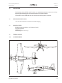
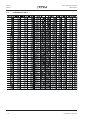
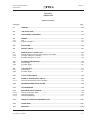

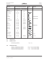
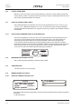
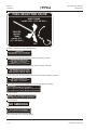
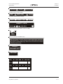
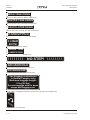
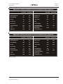
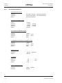
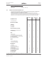
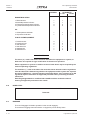


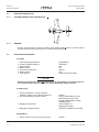
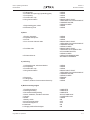
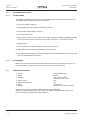
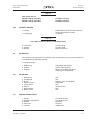
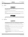

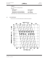
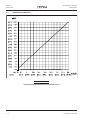
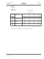
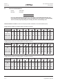
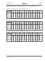

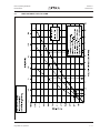
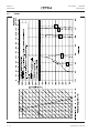
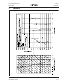
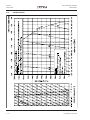
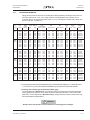
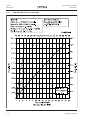
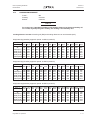
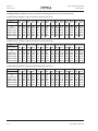

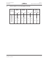
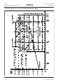
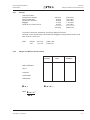
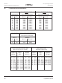
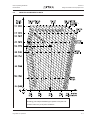
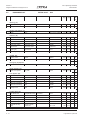
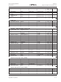
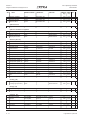
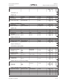
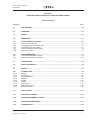

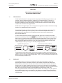
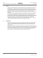
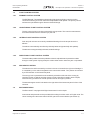
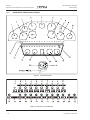
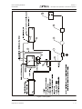
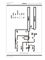
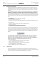
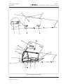


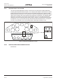


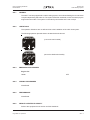
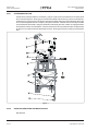

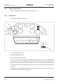
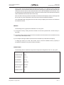


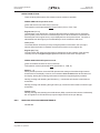


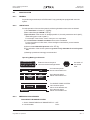
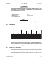
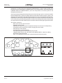
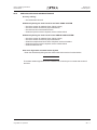


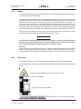
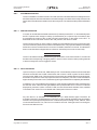
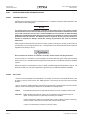
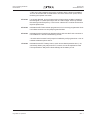


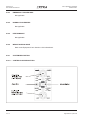
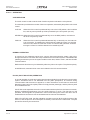
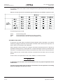
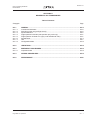

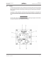

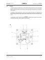
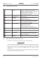
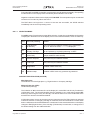
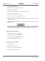
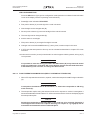

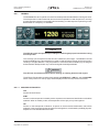

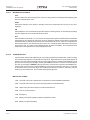


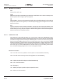
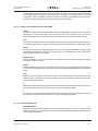
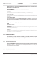
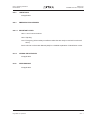


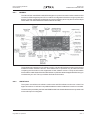


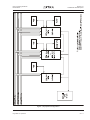

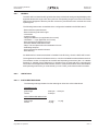
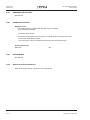
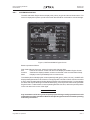
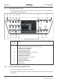
![U.S. Version [Last Updated on: Jun 13th, 2014]](http://vs1.manualzilla.com/store/data/005873845_1-0370c7761d3b42576ec2ae1fd24c9e75-150x150.png)