1
Unicont SPb Ltd
Battery control panel
BCP-136
Operating manual
(136-3-24102013)
St. Petersburg
2013
v.3.4
Unicont SPb Ltd
Operating manual BCP-136
Table of Contents
1. GENERAL .........................................................................................................................3 2. DELIVERY SET ...............................................................................................................3 3. TECHNICAL SPECIFICATIONS .................................................................................4 4. PRINCIPLE OF OPERATION .......................................................................................5 5. ALARMS ...........................................................................................................................7 6. CONTROLS AND INDICATORS ..................................................................................8 7. INSTALLATION AND CONNECTION......................................................................10 8. CONFIGURATION........................................................................................................16 9. TRANSPORTATION AND STORAGE ......................................................................23 10. RECYCLING ..................................................................................................................24 11. WARRANTY ..................................................................................................................25 12. DATE OF PACKING .....................................................................................................26 13. ACCEPTANCE DETAILS ............................................................................................26 14. DATE OF COMMISSIONING .....................................................................................26 APPENDIX A SAILOR 6081 TO BCP-136 CONNECTION EXAMPLE .......................27 Page 2
Unicont SPb Ltd
Operating manual BCP-136
Battery control panel BCP-136 (hereinafter referenced to as battery panel, or panel) is
intended for indication of actual battery charging current and voltage, alarming in case of mains
power failures and battery discharge.
This operating manual describes design and operating principles of the BP, contains
instructions for its installation, configuration, operation, warranty and post-warranty
maintenance.
The manual is intended for those involved in BP installation and configuration, as well
as for BP users. BP installation requires corresponding electric safety qualification.
1. General
Battery control panel BCP-136 ensures 24/7 battery state monitoring by indication of
actual charging/discharging current and voltage, as well as emission of sound and visual alarm
signals in case of 220 V mains power failure, battery discharge and other abnormal situations.
2. Delivery Set
1. Battery panel BCP-136*
2. Connector DB-15F
3. Operating manual
1 pcs.
2 pcs.
1 pcs.
* Battery panel version is defined by the customer when ordering
Battery panel versions:
– BCP-136 (ДИШУ.468262.001) – equipped with analog and digital interface ports
– BCP-136 (ДИШУ.468262.001-01) – equipped with digital interface ports only.
(the versions are described in section 3)
Example of panel designation when ordering:
- BCP-136 (ДИШУ.468262.001) or “BCP-136 with analog interface”
- BCP-136 (ДИШУ.468262.001-01) or BCP-136
Page 3
Unicont SPb Ltd
Operating manual BCP-136
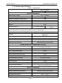
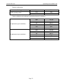
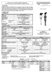
3. Technical specifications
Table 1 - Specifications
BCP-136 version
ДИШУ.468262.001
ДИШУ.468262.001-01
General specifications:
Power supply voltage
10.0 ... 36.0VDC
Power consumption
3.0 W
2.5 W
Galvanic insulation of supply mains
Yes
Reverse polarity protection
Yes
Overvoltage protection
Number of simultaneously connected
batteries
Yes (a fuse)
2 pcs.
2 × RS-422
(digital)
* Note – it is possible to connect external devices to one or simultaneously 2
ports of the panel, but only one of the interfaces can be used for that.
Number of ports () *
2 × RS-422 / analog
Digital interface specifications:
Data exchange with CH-105, PCH-205,
BMU-126
115200 bps
Purpose
Maximal input data rate
Galvanic insulation
Yes
Communication protocol
Proprietary (Unicont SPB)
CH-105, PCH-205, BMU-126
(manufactured by Unicont SPB).
Devices to be connected
Analog interface specifications (BCP-136 only):
Purpose
Battery voltage and current measurement
(by means of a shunt)
Yes
Galvanic insulation of channels
Ushunt measurement range
80 mV
Ubat measurement range
0 – 36 V
Current measurement accuracy
0.01 A
Voltage measurement accuracy
0.01 V
Current indication accuracy
0.1 A (ХХ.Х format)
Voltage indication accuracy
0.1 V (ХХ.Х format)
Input resistance
0.8 MΩ
Allowed shunt resistance
1...9990 µΩ
SB-138 (manufactured by Unicont SPB) and
other shunt based devices
Devices to be connected
General specifications:
Overall dimensions:
211 mm × 117 mm × 55 mm
Overall dimensions with bracket
255 mm × 143.5 mm × 65 mm
Storage temperature
-55°С ... +70°С
Operating temperature
-25°С ... +55°С
Weight
At most 2 kg
Page 4
Unicont SPb Ltd
Operating manual BCP-136
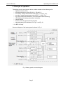
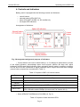
4. Principle of operation
The battery panel is an electronic device, which consists of the following units:
digital processor (CPU),
two data transceiving units (RS-422_1, RS-422_2),
two battery voltage measurement units (ADC_1.2, ADC_2.2)*,
two shunt voltage measurement units (ADC_1.1, ADC_2.1)*,
two relay contact state detectors (for mains power failure alarming)
LED displays (for battery parameters indication),
control buttons,
built-in sound and visual alarming devices,
selected battery LED indicators (ref. Fig. 1 and Fig. 2)
* – for BCP-136 only.
Structural diagram of the battery panel is shown in Fig. 1.
Fig. 1 Battery panel structural diagram
Page 5
Unicont SPb Ltd
Operating manual BCP-136
Battery panel performs the following functions:
selection of operating mode of connected battery chargers,
indication of actual state (current and voltage) of connected batteries,
visual and signal alarming of mains power failure.
Panel BCP-136 supports both digital and analog communication interfaces, while panel
BCP-136-01 supports digital interface only.
Interfaces and external devices to be connected:
digital interface (ref. Fig. 5) – CH-105, PCH-205 or BMU-126. Via the digital
interface, the battery panel connected to these devices receives information on
actual settings, abnormal conditions, charging current and voltage, and displays it
by means the indicator. By means of the panel, it is possible to adjust settings of
CH-105 and PCH-205 (ref. section 8),
analog interface (ref. Fig. 6) – SB-138. It allows to receive charge information from
batteries and other (third parties') external devices.
Battery panel supports simultaneous connection of at most two devices, digital or
analog, in any combination (connection diagrams are shown in section 7).
Page 6
Unicont SPb Ltd
Operating manual BCP-136
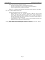
5. Alarms
Battery panel is equipped with built-in means of visual and sound alarming intended to
alert on emergency conditions (ref. Table 2). Used along with CH-105 or PCH-205, the panel
engages these means upon reception of alarms from these devices in digital form (via a digital
channel) (ref. CH-105 and PCH-205 operating manuals, section "Alarms").
Table 2. Battery panel alarms
Connection type
Emergency conditions
Input power failure
(if potential-free contacts are used to
receive signals)
Battery voltage exceeds the specified
level
Battery voltage falls below the specified
level
Discharge current exceeds the maximal
level
Analog
Digital
(BMU-126)
+
+
+
+
+
+
-
+
Digital
(CH-105, PCH-205)
Ref. CH-105 and
PCH-205 operating
manuals, section
"Alarms"
«+» – alarm (visual and sound signals) is switched on
«-» – alarm is not switched on.
In any of the above mentioned conditions battery panel automatically engages the
built-in alarm devices. In order to switch sound alarm signals off, it is necessary to press MUTE
button. However, visual alarm signals will stay active until the cause of the alarm is remedied.
Detailed description of the alarm devices can be found in section 6.
Page 7
Unicont SPb Ltd
Operating manual BCP-136
6. Controls and indicators
Battery panel is equipped with the following controls and indicators:
control buttons,
selected battery LEDs (BAT1/2),
alarm LEDs (BAT ALARM 1/2, AC ALARM 1/2),
two digital LED indicators.
Arrangement of indicators:
Fig. 2 Arrangement and general purpose of indicators.
o Control buttons are used to select battery 1 or 2 to display its parameters by means
of the digital indicators, acknowledge alarm sound signals, perform the lamp test, adjust
brightness of LEDs and digital indicators. Menu navigation buttons make it possible to configure
CH-105 and PCH-205 (connected to digital interfaces) and to adjust shunt and alarm settings
(control button purposes are summarized in Table 3).
Table 3. Purposes of BCP-136 control buttons
Button
MENU
▲ and ▼
Purpose
selection of main menu items (ref. section 8.3).
adjustment of LED brightness, selection of menu item values
ENTER
saving (entering) of the selected menu item value (ref. section 8.3).
BAT 1/2
selection of battery 1 or 2 (ports PORT1 and PORT2) for indication.
MUTE/TEST
switching off (acknowledging) of alarm sound signal (ref. section8.3.9), testing of
LEDs, indicators and the beeper (the test mode, ref. section 8.3.8)
o Alarm LEDs BAT ALARM and AC ALARM (ref. Fig. 2).
Table 4. Purposes of state indication LEDs.
Page 8
Unicont SPb Ltd
Operating manual BCP-136
LED indicator
1 (PORT 1)
BAT ALARM
2 (PORT 2)
1 (PORT 1)
AC ALARM
2 (PORT 2)
Purpose
– if a digital interface is used (along with CH-105 or PCH-205), the
LED is switched on in case of alarm conditions (ref. CH-105 and PCH205 operating manuals, section "Alarms"),
– if an analog interface is used (along with SB-138), the LED is
switched on in case of a deviation from specified charge/discharge
parameters.
– the LED is switched on in case of power supply failure of the battery
charger connected the corresponding panel port,
– the LED is switched on in case of potential-free (dry) contacts
disconnection of the relay connected to the corresponding panel port.
o LEDs BAT1 and BAT2 indicate the selected battery number (1 or 2), parameters of
which are currently shown by digital LED indicators.
o Digital LED indicators show actual values of battery current and voltage. Negative
sign on the LED indicator means negative (discharge) current.
o Residual battery capacity indicator shows residual capacity (power) of the selected
battery. (Currently not in use).
In the standby (primary) operating mode the battery panel indicators display the
following information: selected battery number, actual voltage (the left indicator) and
discharge/charge current (the right indicator) of the selected battery.
If CH-105 or PCH-205 is connected to the digital interface of the battery panel, which
operates in the standby (primary) mode, pressing on ENTER results in that letter "t" appears on
the left digital indicator, while the right one displays actual battery temperature. This function is
supported, provided that that CH-105 or PCH-205 is equipped with a DTS-135 battery
temperature sensor (ref. section 8.3.10 for detailed information). If such sensor is not installed,
the right indicator will display symbols "– – –".
Page 9
Unicont SPb Ltd
Operating manual BCP-136
7. Installation and connection
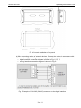
It is recommended to install and connect the battery panel in the following order:
a) The panel must be mounted on a horizontal or vertical surface or on a console.
Select a place for installation and drill mounting holes in accordance with the outline
drawing:
guidelines for desktop or bulkhead installation are shown in Fig. 3,
guidelines for console installation are shown in Fig. 4.
Fig. 3 BCP-136 overall and mounting dimensions for surface installation
Page 10
Unicont SPb Ltd
Operating manual BCP-136
PORT 1
PORT 2
Fig. 4 Console installation of the panel
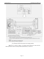
b) Wire connecting cables of external devices. Connect the cables in accordance with
the connection diagram taking into account purposes of the connectors:
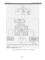
digital interface connection diagram is shown in Fig. 5, Fig. 7;
analog interface connection diagram is shown in Fig. 6.
Fig. 5 Example of PCH-205 (CH-105) connection to the digital interface
Page 11
Unicont SPb Ltd
Operating manual BCP-136
Fig. 6 Example of SB-138 connection to the analog interface
Note! Prior to connect a battery to the battery panel analog port, ensure that the
battery parameters meet the analog interface specifications (ref. section 3).
Page 12
Unicont SPb Ltd
Operating manual BCP-136
Fig. 7 Example of BMU-126 connection to the analog interface
Page 13
Unicont SPb Ltd
Operating manual BCP-136
Assignment of PORT 1 and PORT 2 connector pins:
Table 5. Assignment of PORT 1 and PORT 2 (type DB-15F) connector pins
Pin No.
Circuit
1
2
3
4
5
6
7
8
9
10
11
12
13
14
15
GROUND
NC
Rx –
Rx +
Tx –
Tx +
Rele
Rele
NC
SHUNT SHUNT +
VSUP +
VSUP +
VSUP –
VSUP –
Digital
interface
+
–
+
+
+
+
–
–
–
–
–
+**
+**
+**
+**
Purpose
Analog
interface*
+
–
–
–
–
–
+
+
–
+
+
+**
+**
+**
+**
Power
–
–
–
–
–
–
–
–
–
–
–
+**
+**
+**
+**
* – only BCP-136 (ДИШУ.468262.001) panels are equipped with an analog interface
** – Battery panel power supply and battery voltage measuring circuits are combined in order to decrease the number
of connecting cable wires (to make installation more convenient).
c) Configure the battery panel ports (PORT 1 and PORT 2) for operation with the
corresponding external devices. In order to do it, use the panel service menu (ref.
section 8) to select the connected device type (dCH, dBU, А1, А2) or to switch the
unused off (select OFF)
IMPORTANT! If only one port of the panel is used for connection of an external device,
the second, unused port must be switched off. This will prevent the built-in alarm devices from
false operation.
Page 14
Unicont SPb Ltd
Operating manual BCP-136
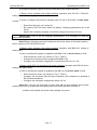
d) Configure the battery panel to receive information from external devices:
1 Battery panel operation with digital interface (operation with CH-105 / PCH-205,
setting of the battery charging specifications)
In order to configure the panel for operation with CH-105 or PCH-205, its main menu
is used.
Enter the main menu (ref. section 8).
By means of BAT1/2 button select the battery, charging specifications are to be
set for.
Specify the necessary charging current and voltage (menu items U and I).
IMPORTANT! Prior to set the charging specifications, it is necessary to read the
battery documentation.
Note! Battery charging current and voltage can be set by means of the battery panel or
built-in controls of CH-105 and PCH-205.
2 Battery panel operation with digital interface (operation with BMU-126, setting of
alarm limits)
In order to configure the panel for operation with BMU-126, its service menu is used.
Enter the service menu (ref. section 8, Fig. 9, Table 7).
Activate the necessary alarms (supported by BMU-126).
Configure the necessary voltage and current alarm limits: Uh, UL, Cth.
3 Battery panel BCP-136 operation with analog interface (operation with SB-138, shunt
settings and alarm limits)
In order to configure the panel for operation with SB-138, its service menu is used.
Enter the service menu (ref. section 8, Fig. 9, Table 7).
Configure the necessary SB-138 shunt resistance (this resistance is specified in
SB-138 documentation).
Configure the necessary voltage alarm limits: Uh, UL.
Note! BCP-136 can be connected to other than SB-138 (non-original) shunt based
measuring devices, provided that shunt parameters meet those specified in section 3.
e) Switch on the panel and check if the readings are correct.
Page 15
Unicont SPb Ltd
Operating manual BCP-136
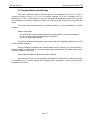
8. Configuration
8.1 Panel menu
In order to configure the battery panel for operation with external devices, its built-in
menu is used.
The panel menu consists of two sections: the main menu and the section menu.
Any of them can be entered when panel operates in the standby (primary) mode (ref.
section 8.3).
Main menu
The main menu of the battery panel is accessible if PCH-205 or CH-105 is connected.
It is used to configure external devices to operate at necessary currents and voltages.
In order to enter the main menu, press MENU button at the panel keyboard (ref.
section 8.3).
Service menu
The service menu is used for initial configuration of the battery panel, in order to
configure types and parameters of connected devices.
The service menu allows to perform the following operations:
configure ports of the battery panel for operation with connected external devices
by setting the corresponding dCH, dBU, A1, and A2 values (ref. Table 7),
switch off unused ports (CH1, CH2 - OFF),
enter shunt parameters of SB-138 (or other device), adjust alarm limits.
In order to enter the service menu, press the corresponding combination of control
buttons (ref. section 8.3).
8.2 Menu structure
The main menu structure is as follows.
Fig. 8. Structure of the main BCP-136 menu.
In dependence of the current operating mode and type of the battery panel (BCP-136
or BCP-136-01), general structure of the service menu may dynamically change. Accessible
settings are show in the service menu diagram (ref. Fig. 9).
Page 16
Unicont SPb Ltd
Operating manual BCP-136
Fig. 9. General structure of the service BCP-136 menu.
Items of the battery panel menu and their functions are briefly described inTable 6 and Table 7.
Table 6. Description of the main menu items
Menu item
Description
I
Selection of battery charging current (varies in a range of 0.1 – 20.0 A)
U
Selection of battery charging voltage (varies in a range of 9.0 – 30.0 V)
IMPORTANT! Prior to set the charging current and voltage, it is necessary to get
familiar with the corresponding recommendations of the battery manufacturer.
Page 17
Unicont SPb Ltd
Operating manual BCP-136
Note! It is necessary to take into account that charging current and voltage (their
maximal and minimal values) are limited in dependence of the connected device type (ref. CH105 and PCH-205 operating manuals).
Note! In case the configured parameters do not meet the selected operating mode of
the port, the error message ("Err") is shown by the indicator.
Table 7 Description of the service menu items.
Menu item
Description
Note
UEr_x.x
Actual firmware version
x.x (number)
Selection of operating mode of the battery panel port (PORT 1, PORT 2)
dCH
Digital port operating mode
(via RS-422 interface)
Connection of external devices
CH-105, PCH-205
dBU
Digital port operating mode
(via RS-422 interface)
Connection of BMU-126 (digital shunt)
A1*
Analog port operating mode
Connection of ZU 6081, 4652, 4656,
Sailor. The panel is connected to the
battery panel BP-4680 terminal, RSh = 100
µΩ (does not change)
A2*
Analog port operating mode
Connection of SB-138
OFF
The port is switched off
External device is not connected
Prt
Selection of the battery panel settings related to reception of analog data from external devices
connected to the analog panel interface (PORT 1, PORT 2)
Set
RSh*
Shunt resistance setting
1...9990 µΩ
For analog shunt SB-138, set RSh = 150
µΩ
Cor*
Zero current correction (varies in a range
of -2.0 – +2.0 А)
ALA*
Alarm setting for connection/disconnection
of terminals
Uh
Upper voltage alarm limit (varies in a
range of 8.0 – 33.0 V)
Activation of alarm if voltage exceeds the
specified value
UL
Lower voltage alarm limit (varies in a
range of 8.0 – 33.0 V)
Activation of alarm if voltage falls below
the specified value
Selection of the battery panel settings related to alarms of BMU-126 connected to the digital panel
interface (PORT 1, PORT 2)
AL
Activation/deactivation of all possible
alarms
ALd
Activation/deactivation of alarm caused by Used only if the battery panel is connected
too high discharge current
to BMU-126
Сth
Activation of alarm if voltage exceeds the
specified value
(accessible for dBU and ALd – ON port
connection types; accessible for A1 and A2
connection types, provided that the
specified value is higher than 0.0)
Maximal discharge current alarm limit
(varies in a range of 0.0 – 9.9 A)
* – These menu items are supported by BCP-136 only
Page 18
Unicont SPb Ltd
Operating manual BCP-136
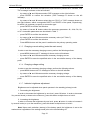
8.3 Battery panel configuration
8.3.1. Port operating mode configuration (enter the service menu)
In order to configure the port for operation with the connected external device type,
perform the following actions:
press ▲ and ▼ buttons simultaneously and hold them pressed for 5 seconds, until
"Prt" message is shown on the left indicator.
press ENTER to confirm the selection ("Prt" message is shown on the left indicator).
by means of ▲ and ▼ buttons select the port ("CH1" or "CH2" message shown on
the right indicator, which corresponds PORT1 and PORT2 of the panel, respectively),
for which it is necessary to specify a connection type.
press ENTER to confirm the selection.
by means of ▲ and ▼ buttons select the necessary connection type (dCH, dBU,
A1, A2). Accessible connection options are described in Table 7.
press ENTER to confirm the selection.
Press MENU button until the panel is switched to the primary operating mode.
8.3.2. Switching off of a port
In order to switch a port off, perform the actions described in section 8.3.1, but select
OFF instead of dCH, dBU, A1, or A2.
8.3.3. Analog interface configuration (accessible for BCP-136 only)
In order to use the battery panel analog interface, it is necessary to specify several
additional parameters (ref. section 7) as follows:
press ▲ and ▼ buttons simultaneously and hold them pressed for 5 seconds, until
"Prt" message is shown on the left indicator.
by means of ▲ and ▼ buttons select "SEt" message on the right indicator.
press ENTER to confirm the selection ("SEt" message is shown on the left
indicator).
by means of ▲ and ▼ buttons select the port ("CH1" or "CH2" message shown on
the right indicator, which corresponds PORT1 and PORT2 of the panel, respectively),
for which it is necessary to specify a connection type.
press ENTER to confirm the selection.
by means of ▲ and ▼ buttons select the necessary parameter: RSh, Cor, Uh, UL,
Cth, or ALA. Accessible parameters are described in Table 7.
press ENTER to confirm the selection
by means of ▲ and ▼ buttons set the necessary value (ref. Table 7).
press ENTER to confirm the selection
Press MENU button until the panel is switched to the primary operating mode.
8.3.4. Digital interface configuration (connection of BMU-126)
In order to use the battery panel along with BMU-126 connected to the digital interface,
it is necessary to specify several additional parameters as follows:
Page 19
Unicont SPb Ltd
Operating manual BCP-136
press ▲ and ▼ buttons simultaneously and hold them pressed for 5 seconds, until
"Prt" message is shown on the left indicator.
by means of ▲ and ▼ buttons select "SEt" message on the right indicator.
press ENTER to confirm the selection ("SEt" message is shown on the left
indicator).
by means of ▲ and ▼ buttons select the port ("CH1" or "CH2" message shown on
the right indicator, which corresponds PORT1 and PORT2 of the panel, respectively),
for which it is necessary to specify a connection type.
press ENTER to confirm the selection.
by means of ▲ and ▼ buttons select the necessary parameter: AL, ALd, Cth, Uh,
or UL. Accessible parameters are described in Table 7.
press ENTER to confirm the selection
by means of ▲ and ▼ buttons set the necessary value (ref. Table 7).
press ENTER to confirm the selection
Press MENU button until the panel is switched to the primary operating mode.
8.3.5. Charging current setting (enter the main menu)
In order to set the necessary charging current, perform the following actions:
press MENU button until "I" message is shown on the left indicator.
by means of ▲ and ▼ buttons set the necessary charging current.
press ENTER to save the specified value in the nonvolatile memory of the battery
panel.
8.3.6. Charging voltage setting
In order to set the necessary charging voltage, perform the following actions:
press MENU button until "U" message is shown on the left indicator.
by means of ▲ and ▼ buttons set the necessary charging voltage.
press ENTER to save the specified value in the nonvolatile memory of the battery
panel.
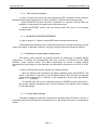
8.3.7. Indicator brightness adjustment
Brightness can be adjusted when panel operates in the standby (primary) mode.
1. Decreasing the brightness
In order to decrease the brightness by one level, press ▼ button. In order to decrease
it by several levels (or down to the minimum), press this button multiple times or hold it.
2. Increasing the brightness
In order to increase the brightness by one level, press ▲ button. In order to increase it
by several levels (or up to the maximum), press this button multiple times or hold it.
Note! Upon each activation (startup) of the battery panel the brightness is set to the
maximal level regardless of the settings made prior to the last switching off.
Page 20
Unicont SPb Ltd
Operating manual BCP-136
8.3.8. Test function activation
In order to check if the visual and sound elements (LEDs, indicators and the beeper),
the panel supports the Test function. In order to activate it, perform the following actions:
press MUTE/TEST button and hold it pressed for 3 seconds, until all LEDs are
switched on, and the built-in beeper emits continuous sound,
release MUTE/TEST button, and the battery panel will return to the primary
operating mode.
8.3.9. ALARMS ACKNOWLEDGEMENT
In case of alarm (ref. Table 4), press MUTE button to switch the sound off.
The beeped stops emitting sound. Visual alarm devices will remain functioning until the
cause of the alarm is remedied. However, they start to light continuously instead of flashing.
8.3.10. Reading the actual battery temperature
The battery panel supports the special function for measuring of charged battery
temperature. It receives the corresponding data from CH-105 or PCH-205 via the digital
interface. These devices monitor the battery temperature by means of digital sensors
(mechanically) fixed directly on the batteries and (electrically) connected to CH-105 or PCH205.
In order to activate this function, perform the following actions:
While the battery panel operates in the primary standby mode, press ENTER. This
results in that letter "t" appears on the left digital indicator, while the right one displays
actual battery temperature. In absence of the temperature sensor the right indicator
shows "– – –" message.
10 seconds after that or upon repeated pressing of ENTER the panel will return in
the primary standby operating mode, and the indicators will display actual charging
current and voltage.
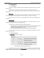
8.3.11. Factory panel settings
The battery charged is delivered configured for operation with PCH-205 or CH-105. It
is assumed that the devices will be connected to port 1. By default, the menu is configured as
follows:
Page 21
Unicont SPb Ltd
Operating manual BCP-136
Default configuration
Setting
PORT operating mode
Item
Value
CH1
dCH
CH2
OFF
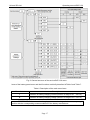
Factory (default) panel settings if the analog channel is activated.
A1 parameter (upon activation)
A2 parameter (upon activation)
Page 22
RSh
100 µΩ
Cor
- 0.9 A
Uh
29.5 V
UL
23.5 V
Cth
OFF
ALA
Ope
RSh
150 µΩ
Cor
- 0.9 A
Uh
29.5 V
UL
23.5 V
Cth
OFF
ALA
Ope
Unicont SPb Ltd
Operating manual BCP-136
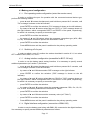
9. Transportation and Storage
The divice shall be stored in heated space at air temperature of +5 ºС to +35 ºС
(maximum values of -55 ºС to +70 ºС), at relative humidity of air not exceeding 95 % at
temperature of +25 °C and content of dust, oil, moisture and aggressive admixtures in the air
not exceeding the norms envisaged by GOST 12.1.005-88 for the working zone of production
areas.
The device shall be transported in transport container of the manufacturer in closed
transport.
Means of transport:
automobile and railway closed transport (covered wagons, universal containers)
by air (in pressurized and heated bays of airplane)
by sea (in dry service spaces).
The device shall be transported in accordance with the transport regulations in force
for the particular transport.
During handling operations and transportations strictly observe the requirements of
handling marks on boxes and do not allow bumps and impacts which can affect preservation
and serviceability of the device.
Packed devices shall be reliably secured in vehicles.
After storage in stores or transportation at temperature below +10 ºС the devices shall
be unpacked only in heated spaces after keeping them unpacked in under normal climatic
conditions for12 hours.
Page 23
Unicont SPb Ltd
10.
Operating manual BCP-136
Recycling
Do not recycle the packing of a new product, its parts with defects identified during its
operation as well as the overage product as common household waste since they contain
materials and raw materials suitable for their recovery.
Decommissioned and unused components should be delivered to a specialized waste
collection center licensed by local authorities. You can also send the overage equipment to the
manufacturer for its further recycling.
Proper recycling of the product components will prevent potential negative
consequences for human health and the environment, as well as provide recovery of the
product component materials while substantially saving on energy and resources.
The product does not endanger human life and health or the environment during
and after its service life.
This product should be recycled following the requirements applicable to
electronic equipment.
Products marked with a crossed-out recycle bin should be recycled apart
from common household waste.
Page 24
Unicont SPb Ltd
Operating manual BCP-136
11. Warranty
The manufacturer guarantees the unit BCP-136 complies with this manual provided
that the operation, transportation and storage conditions are adhered to during the warranty
period.
The unit’s warranty period expires 24 months from the date of its shipping from the
manufacturer’s storehouse.
Within the warranty period, the owner is entitled for a free repair, or a replacement of a
separate part, provided that the malfunction occurred through the manufacturer’s fault.
Warranty repair is provided if the unit is submitted with the manufacturer’s label and a
legible serial number available on it, as well as this operating manual.
The manufacturer is not responsible and cannot guarantee the unit’s operation:
1. After the warranty period is over;
2. In case of the failure to observe the unit’s operation, transportation, storage and
installation rules and conditions;
3. If the unit is in an unmarketable condition, or has a damaged body, and other
causes beyond the manufacturer’s control;
4. If self-made electrical devices were used.
5. If there was an attempt to repair the unit by a person who is not an authorized
representative of the manufacturer.
If the owner loses this operating manual or the manufacturer’s label with a serial
number, the manufacturer shall not provide their copies, and the owner shall be divested of the
right for a free repair during the warranty period.
Upon the warranty expiry, the manufacturer shall facilitate the repair of the unit at the
owner’s expense.
Note: in case of warranty repair, the unit’s disassembling from the installation site and
its delivery to the manufacturer’s service center are done at the owner’s expense.
Visit the manufacturer’s website www.unicont.spb.ru (section “support/warranty”) to
find:
forms to fill in claims,
full warranty description;
full description of the warranty service rendering procedure.
The manufacturer service center’s address and contact details:
Unicont SPb, Ltd.
Bld. 26Е Kibalchich Str., Saint Petersburg, 192174, Russia
tel.: + 7 (812) 622 23 10, +7 (812) 622 23 11
fax: +7 (812) 362 76 36
e-mail: [email protected]
Page 25
Unicont SPb Ltd
Operating manual BCP-136
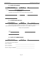
12. DATE OF PACKING
Battery control panel
BCP-136
name of article
designation
Packed
№
serial number
Unicont SPb Ltd, Russia.
Manufacturer
according to the requirements of the current technical documentation.
post
signature
clarification of signature
year, month, day
13. ACCEPTANCE DETAILS
Battery control panel
BCP-136
name of article
designation
№
serial number
was manufactured and accepted in accordance with the regulatory requirements of the
state standards and applicable technical documentation, and is suitable for operation.
Quality control representative
Stamp
here
signature
clarification of signature
year, month, day
14. DATE OF COMMISSIONING
Battery control panel
BCP-136
name of article
designation
№
serial number
The unit has been put into operation.
Date of installation:
___________________________________________
Place of installation:
___________________________________________
Person in charge of installation: _________________________________________
Page 26
Unicont SPb Ltd
Operating manual BCP-136
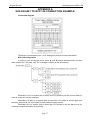
APPENDIX A
SAILOR 6081 TO BCP-136 CONNECTION EXAMPLE
Connection diagram
The device is connected to port 1 or 2. Settings for the first port are listed below.
BCP-136 configuration
In order to enter the service menu, press ▲ and ▼ buttons simultaneously and hold
them pressed for 5 seconds, until "Prt" message is shown on the left indicator.
Parameter Cor В (of section Set) of menu item CH1 allows to set the current offset (in
order to correct the current readings).
Parameters Uh and Ul (of section Set) of menu item CH1 allow to set the upper and
the lower alarm limits (for the minimal and the maximal voltage levels).
Parameter ALA (of section Set) of menu item CH1 allows to set the alarm level (for
connection and disconnection of terminals).
Page 27