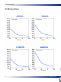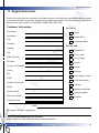
1
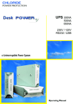
CHLORIDE
POWER PROTECTION
o
o
o
o
o
o
Uninterruptible Power System
Unterbrechungsfreie Stromversorgung
Sistema de Alimentación Ininterrumpida
Alimentation Sans Interuption
Sistema Statico di Continuita
Sistema de Fornecimento de Energia Initerrupto
Cool Power
600
900
1200
1600
Operating Manual
Bedienungsanleitung
Manual de usuario
Manuel utilisateur
Manuale d’Uso
Manual de instruçöes
All rights, including rights of translation, reproduction by printing, copying or similar methods, even
of parts, are reserved.
Offenders will be liable for damages.
All rights, including rights created by patent grant
of registration of utility model or design, are reserved.
Delivery subject to availability. Right of technical
modification reserved.
Operating Manual
Safety Instructions
Caution
Explicación de símbolos
7
7
8
1.
Introduction
9
2.
2.1
2.2
Unpacking the Unit & Contents
Unpacking the Unit
Package Contents
10
10
12
3.
Installation
12
4.
4.1
4.2
Display and Operating Components
Front view
Rear view
15
15
16
5.
5.1
5.2
5.3
5.4
5.5
Equipment Operation
Working modes
Indicator lights
Push button Operation
Acustical signals
Voice and Data Lines Protection
18
18
18
19
20
20
6.
6.1
6.2
6.3
6.4
Description of Communication Interfaces
Standard COM Interface
SNMP Adapter
Cable 59
Cable 61
21
21
22
22
22
7.
7.1
7.2
Mantenance
Storage
Cleaning
23
23
23
8.
Troubleshooting
24
9.
Technical Data
25
10.
Backup Times
26
11.
Registration Form
27
12.
Chloride Address
29
945012.066
REV: 16/03/01
5
Operating Manual
6
REV: 16/03/01
945012.066
Operating Manual
Safety Instructions
!
Read the following information carefully!
The failure to follow these instructions could endanger your life, your health, the operation of
the equipment or the security of data.
- The UPS satisfies safety regulations relative to information systems and electronic machines used
in offices. If you have any questions, contact your after sales service.
- Use the right packaging for transport (protection against bumps and blows).
- The unit is equipped with a power line in compliance with safety norms and should only be connected to a grounded plug.
- The button
(see chapter entitled “Button operation) does not insulate the unit from the mains.
In the event of a disconnection of mains voltage, the built-in battery will continue to supply energy to
the load.
- The power cords should be arranged in such a way as to prevent people from stepping on them or
tripping over them. When installing the unit, follow the instructions in the chapter on “Installation and
Operation”.
- Data transmission lines should not be connected or disconnected during storms.
- Prevent objects from falling into the equipment (necklaces, paper clips, etc.).
- In the event of an emergency (deterioration of the case, control or line element, penetration of liquids
or foreign bodies), disconnect the equipment, remove the connection to the mains and call your after
sales service.
CAUTION:
1. The equipment must be at least 10 cm away from the wall
2. Make sure there are no objects blocking the vent.
3. Do not place the unit near heat sources or in places exposed to direct sunlight, dust, water or
mechanical blows.
4. The equipment should only be installed in areas where the temperature is controlled and free of
conductive contaminants.
5. Use approved connection cables which support at least the voltage and intensity specified on each
model.
6. The incoming and outgoing wires must always be accessible to the user.
7. In compliance with the eletromagnetic compatibility standard (EN 50091-2) the total length of the
output cables must not exceed 10m. Likewise, the communication cables must not exceed 3 m. in
length.
8. The sum of the leakage current of the loads connected to the UPS should not exceed a total of
2.8mA.
9. Before disconnecting the UPS from the mains, disconnect the output cables connected to the load.
10. Never open the equipment. It should only be opened by qualified technical personnel. It contains
elements which have a charge even with the equipment turned off.
945012.066
REV: 16/03/01
7
Operating Manual
WARNING: There is a high risk of electrical “shock” from the battery and a high short-circuit intensity.
Remove all watches, rings and other metal objects and use only insulated tools when
replacing the battery.
WARNING: Do not expose the battery to fire; it can explode.
WARNING: Do not open the battery. The electrolyte can be dangerous to the eyes and skin when spilled. It may be toxic.
Explanation of Symbols
The meaning of the symbols used in this manual are the following:
The failure to follow these instructions could endanger your life, your health, the operation of
the equipment or the security of data.
The author proposes supplementary information and advice.
The text below describes the procedure to be followed.
8
REV: 16/03/01
945012.066
Operating Manual
1. Introduction
Installed between the mains and the load, the Uninterrupted Power System (UPS) protects electronically sensitive equipment against disturbances and particularly against electric power failures.
This UPS works on the Line Interactive principle. This means that the connected equipment is powered from the mains after passing through a voltage stabilizer and diverse filters. This reduces disturbance from the mains which in turn increases the safety level of equipment operation (PCs, servers,
distributed systems, etc.). In the event of a mains failure, the built-in, maintenance-free battery assumes the uninterrupted supply of energy to the connected equipment. The energy from the UPS enables the system to keep working until the mains power returns or, in the event of a prolonged outage,
the UPS will inform the user when all processes must be terminated and the system shut down.
The UPS indicates by acoustical (buzzer) and optical (LED) alarms that a mains failure has occurred
or persists in order to end all tasks as necessary.
These operating instructions contain all of the information necessary for the installation and operation
of the UPS.
The UPS has an auxiliary outlet with a filter for surges, electrical noise and transient voltage for noncritical loads which is not battery-powered.
This UPS is equipped with a protection device for voice and data lines patented by ONEAC
Corporation. It protects fax, modem or local network boards from cable disturbances (noise and dangerous voltage peaks). This protection device improves the quality of communications by accelerating
data transmissions and eliminating static from voice calls.
945012.066
REV: 16/03/01
9
Operating Manual
2 Unpacking the Unit and Contents.
Upon receipt of the unit and prior to unpacking it, make sure that there are no visible signs of damage on the outside of the box. If any damage is observed, notify the carrier.
Also observe the date of the last recharge which is located on the side of the box (see Figure “A”). Not
the reception date of the equipment and recharge the battery once the equipment has been unpacked.
Figure A.
2.1 Unpacking the Cool Power
The procedure for unpacking the unit is described below:
1.- There should be a clean, obstacle-free
surface available for unpacking the
equipment.
10
2.- Open the box, remove the documentation and cables (manual, power
cords and communication cables).
REV: 16/03/01
945012.066
Operating Manual
3.- Place the equipment on the open side
of the box, leaving the flaps of the box
open underneath the equipment.
5.- Remove the protective materials from
the unit.
945012.066
4.- Lift the box off.
6.- The equipment is now ready for connection and start-up.
REV: 16/03/01
11
Operating Manual
2.2 Contents:
- UPS unit:
- 2 power cables for
connection to UPS outlet
- User manual.
- Communication cord:
– Registration and software download card:
3. Installation
No prior knowledge is required to install this equipment.
1. Connect the outlets on the back of the UPS to the equipment to be protected using the IEC320 type
cables for the 230V model or NEMA 5-15R for the 115V model. Make sure that the total connected
load does not exceed the useful power range of your UPS.
12
REV: 16/03/01
945012.066
Operating Manual
2. Connect the selected load (i.e. printer, scanner) to the surge protected outlet. Appropriate loads are
those elements that demand surge protection, but that do not require extended runtime during power
outages.
3. If monitoring software is to be used, connect the comm cable between the UPS COM port (DB-15)
and the computer’s COM port (DB-9).
4. Connect the power cord to the UPS.
5. Plug the power cord into the mains. The computer’s power cord may be used.
945012.066
REV: 16/03/01
13
Operating Manual
6. Once connected to the mains, check to make sure that the LED on the front panel is green within
a few seconds. Immediately after connecting the UPS to the AC network the equipment runs a selftest. If the test is successful and the electricity supply is within the specified limits, the equipment will
start up and will supply energy to the output connectors.
7. Start up the protected equipment.
The voice and data line is connected for protection as shown on the input and output on the equipment panel.
When the equipment is started, the batteries in the UPS are automatically charged. The UPS may be
used immediately even through the batteries have not been fully recharged. In this case, however, the
maximum residual capacity will not be available (complete discharge time).
Before running any tests, the batteries must be recharged for at least 6 hours.
Do not connect any equipment which could overload the UPS or draw continuous current from
the UPS (e.g.: hair driers, vacuum cleaners, etc.).
The UPS may be used even without being connected to the mains. To do so, the batteries must
be sufficiently charged. See “Button Functions”.
14
REV: 16/03/01
945012.066
Operating Manual
4. Display and Operating Components
4.1 Front View
All of the models in this range have the same display element located on the front panel. They are as
follows:
Battery level
Operating status
Alarm indicator
1. Battery level
: Indicates the charge level of the battery. For more information see Part 5.2.
2. Working status
: The color green indicates that the network is within the tolerance limits; the
color red indicates that it is outside of the acceptable limits. more information
see Part 5.2.
3. Alarm indicator
: The color red indicates an overload or temperature alarm. For more information see Part 5.2.
945012.066
REV: 16/03/01
15
Operating Manual
4.2. Rear View
Depending on the model and the power, the elements may be arranged differently on the rear panel..
Each one of the models is described below:
1
1
2
2
5
5
7
6
7
6
4
4
3
3
Cool Power 600 115V
Cool Power 600 230V
2
2
1
1
5
5
3
3
4
4
6
6
7
7
Cool Power 900/1200 230V
16
Cool Power 900/1200 115V
REV: 16/03/01
945012.066
Operating Manual
1
2
7
1
2
5
5
6
6
4
7
4
3
3
Cool Power 1600 230V
1. Battery test
Cool Power 1600 115V
: This button enables you to run a battery test, switch off the UPS and restart
it without mains electricity. For more information see Part 5.3.
2. Communication Port : Basic (signals) and advanced (using RS232 protocol) communication port.
For more information see Part 6.
3. Telephone and data
line protection
: Filtering of electric noise on data transmission lines. For more information
see Part 5.5
4. Battery protected and
filtered outlet
: Outlet protected for critical loads requiring additional electricity.
5 Filtered outlet
: Outlet protected against surges for non-critical loads.
6. Input
: IEC type connector for connecting the power cord of the protected load.
7. Circuit breakers
: Protects against short-circuits, electronic fuse with reset.
945012.066
REV: 16/03/01
17
Operating Manual
5. Equipment Operation.
5.1 Working modes.
This UPS works automatically without the use of a switch. It starts up automatically when there is
power from the mains.
When the electricity is within acceptable frequency and voltage margins, the LED
on the front
panel is green and the equipment recharges the battery. When outside of the acceptable margins, the
LED
is red and uses power from the battery to supply protected critical equipment.
To shut down the equipment, simply shut down the protected equipment. When there is no electricity
from the mains, if the UPS does not detect any usage it shuts down automatically within 30 seconds.
This makes it possible to shut down the general power supply without wearing down the batteries.
See special push button functions for starting up and shutting down the UPS. Part Aptdo. 5.3
NOTE: When the unit is switched off it goes into a stand-by mode during which it draws energy from
the batteries to keep the electronics working for a certain period of time while waiting for the power to
return. If the power failure lasts longer than the allowed stand-by time, the equipment will shut down
completely. When the power comes back, the process will be similar to start-up.
This UPS has a three-stage output voltage regulator: trim, central and boost.
This ensures a wide range of input voltages (without having to run down the battery) and at the same
time that the output voltage is always within acceptable margins. This guarantees that the batteries
are recharged even with anomalous input voltages while protecting the connected equipment. To
ensure maximum autonomy following a total battery rundown, the UPS must be charges for at least 6
hours.
The unit is equipped with a “circuit breaker with reset” for overload protection. If the circuit breaker
trips, remove the cause of the overload and rest the circuit breaker.
5.2 Indicator Lights.
The indication lights on the front panel enable fast and easy identification of the operating status of
the equipment. The different elements are described below:
18
REV: 16/03/01
945012.066
Operating Manual
· The green LED indicates that the equipment is working in line mode.
The red LED indicates that the equipment is working in battery mode,
powering the protected equipment from the battery.
· This LED indicates an alarm. A blinking red light indicates that the
equipment has shut down due to the persistence of an alarm. Try to
ascertain he cause of the alarm (temperature or overload).
Red LED statuses:
Off:
Solid red:
Blinking red:
no alarms.
equipment with alarm (acoustical also).
the equipment has shut down due to a persistent alarm.
· A set of LEDs which indicates the estimated recharge status of the batteries at all times, indicating the following levels: 25, 50, 75 and 100%.
If these LEDs are blinking it means that the battery is defective after
having run a battery test. In this case, the batteries must be recharged
for at least 6 hours followed by another battery test. If the same battery
failure occurs at this point, the batteries must be replaced.
NOTE: only applies to 115V models: There is an indicator on the rear panel of a defective grounding
connection. If this indicator is lit, the electrical installation should be checked (On the Rack version,
this indicator light is located on the front panel).
5.3 Push Button Operation
On the rear panel of the equipment there is a “push button” which performs several different functions
depending on the initial status of the equipment (In the Rack version the button is located on the front):
· If the equipment is operating normally, pressing the button for approximately 2 seconds will test the batteries.
. If the equipment is operating normally and the button is held down for
more than five seconds, the unit will shut down and move into a standby mode (The equipment will restart at the end of the configured standby time if there is power from the mains in order to prevent the battery
from being completely worn down) Attention: it is not a real permanent
shutdown.
· If the UPS is turned off and the button is pressed for more than 2 seconds, the unit will start up and
provided output voltage which will come from the batteries when there is no mains power and the batteries are sufficiently charged.
945012.066
REV: 16/03/01
19
Operating Manual
5.4 Acoustical signals
In the event of any anomaly or notable event, the UPS has a buzzer which emits a series of beeps.
The acoustical signals will depend on the operating status of the equipment. The different situations
in which the buzzer may be activated are as follows:
- Battery Mode: One «beep» every 15 seconds indicates that the voltage is outside of the window
of tolerance and the UPS is powering the protected load with battery power.
- Self-Test Mode: A series of five «beeps» every 5 seconds. The UPS runs an internal self-test
when turned on.
- Pre-Alarm Mode: One «beep» every second, ongoing. The UPS indicates that the battery is
almost completely worn down and that its autonomy is about to come to an end.
- Historical Mode: Two «beeps». An event has occurred which is registered and memorized in the
“HISTORICAL” log.
- Alarm Mode: Four short «beeps» and one long «beep» per second. A user alarm has gone off
(overload or temperature).
5.5 Voice and Data Line Protection.
The UPS Cool POWER models includes a protective filter for voice and data lines. The load is thus
protected not only against electrical disturbances (UPS) but also against potential anomalies in the
voice and data lines which can damage the protected load (protective filter for communications).
This filter has been designed and patented by the prestigious ONEAC Corporation, a member of the
CHLORIDE POWER PROTECTION Group.
Patent Nº:
US 4.758.920
CAN 1.286.812
EPC 388.107(UK, FRA)
GER P3861679.3
AUSTRALIA 593.437
Input impulse
Impulse between A and B
Telephone Line / TLP
10/1000µs,1.5kV, 75 A
520V *
95V *
50 A
100 A
0-1kV 100V/s
Break voltage Vcc
Impulse between A and B
Loop resistance
Permanent current
Response time
Insulation resistance
Ground line capacity
Impulse between A and B
Data Line / DLP
10/100µs, 1.5kV
520V *
320V*
12 a 18 Ω
≥ 150 mA
< 1 ns
> 100 MΩ
50Vcc, 1Vca, 10kHz-1MHz
< 200pf
< 200pf
35V *
65V *
7,5V *
≤ 0.5 Ω
< 5 ns
> 50 kΩ
0Vcc, 1Vca,1MHz
< 50pf
Surge protection
Without reset (fuse with delay)
Operating voltage (1A)
Service life
300 mA
1A
< 5V
± 10 A
± 75 A
Operating temerature
Storage temperature
With impulses of 10/1000 µs
Unlimited
Unlimited
-40ºC to 65ºC
-40ºC to 85 ºC
* Typical values
20
REV: 16/03/01
945012.066
Operating Manual
6. Description of Communication Interfaces.
6.1 Standard COM Interface
Cool POWER offers a standard interface which makes it possible to transfer data on an RS232 serial communication protocol. The same interface provides for basic signaling communication using dry
contacts.
Both types of interface are combined in a 15-pin Sub-D connector with the serial communication signals, 2 output signals and 1 input signal, all with voltage levels according to the V24 standard.
The equipment comes with a communication cable with a 9-pin Sub-D connection on one end and a
15-pine Sub-D connector on the other.
Both communication systems can be used for:
· Direct communications between the UPS and the computer (PC)
· Installing the UPS is a centrally controlled network
Transferring basic operating statuses in external signaling systems
The connector pins are described below:
- The logic of the low battery and network failure signals can be configured in the software.
- The “remote shutdown” input signal can be enabled or disabled
from the software and is active at logical level “1” (takes 5 seconds
to act).
1 - Low battery
: Signal that the battery’s autonomy is coming to an end
2 - TDO
: Serial communication output
3 - RDI
: Serial communication input
4 - Remote shutdown : Remote UPS shutdown input signal
5 - GND
: ground
9 - +5V @ 10mA : 5V signal
11 – Network failure: Network failure output signal
945012.066
REV: 16/03/01
21
Operating Manual
6.2 SNMP Adapter.
Cool Power units have an SNMP management hardware option called ManageUPS. This innovative
device enables us to communicate and monitor the status of the UPS through the network with an
SNMP/Telnet management program.
It also includes a Web Browser which enables us to monitor through an Internet browser (Internet
Explorer, Netscape). By adding the MopUPS software, we are able to do an orderly shutdown of the
operating system.
6.3 Cable 59
This enables us to manage the equipment’s basic signals (low battery, network failure) and to initiate
the shutdown of the operating systems included with the UPS service (NT, Linux, Novel S.X y OS/2)
without interrupting the RS232 communication.
5
4
3
2
1
9
8
7
6
1
2
3
4
5
8
– Low battery
-RXD
-TXD
– Remote Shutdown
- GND
– Mains failure
6.4 Cable 61
This option enables us to have the basic network failure and low battery signals free from potential
without interrupting the RS232 communication. The following operating systems are commonly used:
AS400, RISC 6000 and NT. This cable must include the adapter cord for each operating system. E.g.:
Cable 61 plus AS400 A cables.
Cable 61 includes an interfaces with jumpers to modify the logic of the contacts.
It leaves the factory with positive logic in all basic signals.
Input
Output
Mains
failure
22
Low
Battery
REV: 16/03/01
945012.066
Operating Manual
Signal
Network failure
Jumper
J3
Low battery
J4
Jumper on
Jumper off
Network bad – Contact closed
Network good – Contact open
Battery bad – Contact closed
Battery good – Contact open
Network bad – Contact closed
Network good – Contact open
Battery bad – Contact closed
Battery good – Contact open
7. Maintenance
This UPS does not require any maintenance by the user except when the batteries wear out and must
be replaced.
The typical lifetime of a battery is 4 years at a room temperature of 25 °C, although this will also
depend on the working conditions.
Regularly check the unit’s residual capacity time to ensure that it is sufficient, at least once
every 12 months.
7.1 Storage
For long time storage in moderate climates, the batteries should be charged 6 hours every three
months. Repeat it every two months in high temperature locations.
The recharging procedure is described below:
Connect the UPS to a grounded outlet.
Unplug the unit after 6 hours.
Note the charge date, preferably by marking the packing in the area reserved for this purpose.
7.2 Cleaning
Before cleaning, you should switch off the UPS and pull the plug out of the socket after disconnecting the load.
Do not use scouring powder, aggressive detergents or spray cleaners to clean the UPS.
Be particularly careful not to block vents.
945012.066
REV: 16/03/01
23
Operating Manual
Do not allow the liquid to get inside the UPS.
Clean the outside of the UPS housing by wiping with a dry or a slightly wet cloth.
8. Troubleshooting
If a problem occurs despite the high reliability of the device, please review the following table before
calling the service center.
- Is the UPS plugged into a correctly working outlet ?
- Has a fuse blown or the protector on the rear panel tripped?
- If the problem persists, please note the following information when you call for service:
A. Information about the device (model, order number, serial number from type plate, date of purchase and date of installation)
B. Full description of problem (which load is connected, does the problem occur regularly or sporadically, etc.)
Problem
Possible Cause
Corrective Action
No signaling
No power from mains.
Check the status of the electricity
supply
Reset. If the problem persists,
consult your after sales service.
No alarm
(the
UPS
disconnected)
is The protection switch has been
activated
Problem
Possible Cause
Indicator light is not on The input protection switch has
but there is power from reacted.
the mains.
The acoustical ALARM Overload
light is on
Residual capacity time
is less than the value
indicated.
Overheating
Batteries not fully charged.
Batteries are defective
efective charging system
24
REV: 16/03/01
Corrective Action
Reset. If the problem persists,
consult your after sales service.
Reduce the load. (Eliminate the
protected equipment until the
anomaly disappears)
Reduce the ambient temperature
Charge batteries (see 3.1 startup) and check the autonomy
time.
If the problem persists, consult
your after sales service.
945012.066
Operating Manual
9. Technical Data
Models
INPUT
Nominal voltage
Voltage range
Frequency
OUPUT
Nominal voltage
Voltage regulation
Frequency
Power
Power factor
INVERTER
Wave factor
Nominal voltage
Crest factor
Transfer time
Frequency
BATTERY
Technology
Floatation voltage
Charger current
Recharge time for 80%
Battery test
SIGNALES & COM
DB15
OTHER
Working temperature
Relative humidity
Maximum altitude
without degradation
Dimensions
(height-width-depth)
Weight
600
900
1200
1600
Vac
Vac
Hz
230/115
180-285 (ver. 230V) / 90-142 (ver. 115V9
50/60 ± 4% automatic selection
Vac
230/115
198-258 (ver. 230V) / 98-128 (ver.115)
50/60 (see input frequency)
900
1200
540
720
0.6
Hz
VA
W
600
360
Regulated pseudosenoidal
230/115
3:1
<4
50/60 ± 0,1 %
Vac
Ms
Hz
Vdc
A
H
1600
960
13,6
Hermetic lead, maintenance-free
27,2
0,8
<6
Programmable/Automatic/Manual
1,7
RS-232 serial communication
"Network failure " and “Low battery” (RS-232 configurable logic)
"Shutdown" initiation signal
ºC
%
0 to 40
90 without condensation
m
3000
mm
Kg
155x105x345
10
Protection level
CERTIFICATES
170x140x345
14,5
IP21
308x140x365
23
EN52091-1 (Ver. 230 V)
UL 1778 (ver. 115 V)
EN50091-2 (Ver. 230 V)
IEEC 062.41 Cat. A
The company reserves the right to changes thes specifications without prior notice.
945012.066
REV: 16/03/01
25
Operating Manual
10. Backup times
Time (min.)
Time (min.)
LOAD %
LOAD %
Time (min.)
Time (min.)
LOAD %
26
LOAD %
REV: 16/03/01
945012.066
Operating Manual
11. Registration form.
Please fill out this form as completely as possible. None of the fields are required but the information
you provide will help us make our service better suited to your needs. The information you enter below
will never be used outside of CHLORIDE POWER PROTECTION.
Customer Information
For use in:
First Name
:
Last Name
:
Title
:
Company
:
Address
:
City
:
State/Province
:
Zip Code
:
Home
Small Office
Corporate Office
For use with:
Desktop PC
PC on LAN
PC on WAN
Server
Country of purchase:
Printer
Phone
:
Fax
:
Email
:
Scanner
Hub, Bridge, Router
CAD Workstation
Product information
Telecom
Model
:
Serial number
:
Date of purchase
:
Purchased form
:
Medical equipment
Security system
Process
Other:
Comments, remarks, suggestions...
Thank you for registering your product!
Note: Please fill in this form and submit to Chloride Office.
945012.066
REV: 16/03/01
27
28
REV: 16/03/01
945012.066
CHLORIDE WORLD HEADQUARTERS
Chloride Power Protection
George Curl Way
Southampton
Hampshire, SO18 2RY
United Kingdom
Telephone: +44 (0) 23 8061 0311
Facsimile: +44 (0) 23 8061 0852
[email protected]
AUSTRALIA
Chloride Hytek PTY LTD
Units C1A and C1B
Centrecourt Business Park
25-27 Paul Street North
North Ryde NSW 2113
Australia
Telephone: +61 2 9888 1266
Facsimile: +61 2 9888 1966
[email protected]
FRANCE
Chloride Industrial Systems
30 Avenue Montgolfier - BP 90
F-69684 Chassieu Cedex
France
Telephone: +33 4 7840 1356
Facsimile: +33 4 7890 5890
[email protected]
Chloride Power Protection
1 rue Felix Potin
ZA Les Belles Vues
91290 Arpajon
France
Telephone: +33 1 6926 1281
Facsimile: +33 1 6083 1816
[email protected]
Chloride Telecom Systems
ZA Les Rolandières
35120 Dol de Bretagne
France
Telephone: + 33 299 48 2068
Facsimile: + 33 299 48 3394
[email protected]
GERMANY
Masterguard
Schallershofer Str. 141
D-91056 Erlangen
Germany
Telephone: +49 9131 9855 100
Facsimile: +49 9131 9855 270
[email protected]
ITALY
Chloride Silectron
Via Fornace 30
40023 Castel Guelfo
Bologna
Italy
Telephone: +39 054 2632 111
Facsimile: +39 054 2632 120
[email protected]
PORTUGAL
Chloride Power Protection
Rua dos Tercos 574
Zona Industrial de Canelas
4405 270 Canelas VNG. Oporto
Portugal
Telephone: +351 22 7151 210
Facsimile: + 351 22 7126 337
[email protected]
SPAIN
Chloride Boar
Azufre 8-10
Polígono Industrial Sur
28770 Colmenar Viejo, Madrid
Spain
Telephone : +34 91 848 84 00
Facsimile : +34 91 845 51 32
[email protected]
THAILAND
Chloride Power Electronics LTD
Panjathani Tower, 20th Floor
127/25 Nonsee Road
Chongnonsee, Yannawa
Bangkok 10120
Thailand
Telephone: + 662 6810 100
Facsimile: + 662 6810 109
[email protected]
TURKEY
Masterguard
Sebnem Sok. Nº 14, Kat: 3-4-7-8
81110 Bostanci Istambul
Turkey
Telephone: +90 216 464 47 00
Facsimile: +90 216 464 47 15
[email protected]
UK
Chloride Power Protection
George Curl Way
Southampton
Hampshire, SO18 2RY
United Kingdom
Telephone: +44 (0) 23 8061 0311
Facsimile: +44 (0) 23 8061 0852
[email protected]
INTERNATIONAL SALES
Europe, Middle East and Africa
Chloride Power Protection
George Curl Way
Southampton
Hampshire, SO18 2RY
United Kingdom
Telephone: +44 (0) 23 8061 0311
Facsimile: +44 (0) 23 8061 0852
[email protected]
Chloride Industrial Middle-East (CIME)
PO Box 17693
Dubai
United Arab Emirates
Telephone: +971 (4) 881 8848
Facsimile:+971 (4) 881 4518
Oneac UK
18 & 20 Blacklands Way
Abingdon Business Park
Abingdon
Oxfordshire, OX14 1DY
United Kingdom
Telephone: +44 (0) 1235 534 721
Facsimile: + 44 (0) 1235 534 197
[email protected]
Latin America
Chloride Power Protection Latin America
Rua Arizona 1349
Brooklin Novo
Sao Paulo CEP 04567-002
Brazil
Telephone: +55 11 5505 4661
Facsimile: +55 11 5505 4832
[email protected]
USA
Chloride Power Protection
28430 N. Ballard
Lake Forest IL 60045
USA
Telephone: +1 800 239 2257
Facsimile: +1 800 833 6829
Asia Pacific
Chloride Power Protection
80 Marine Parade Road
#10-08 Parkway Parade
449269
Singapore
Telephone: +65 348 5288
Facsimile: +65 348 3400
[email protected]
Oneac Corporation
27944 North Bradley Road
Libertyville
Illinois 60048-9700
USA
Telephone: +1 847 816 6000
Facsimile: +1 847 680 5124
[email protected]