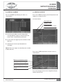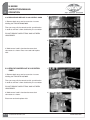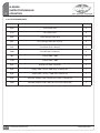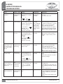
1
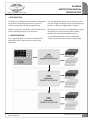
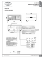
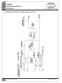
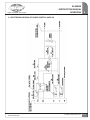
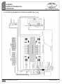
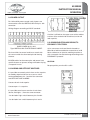
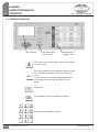
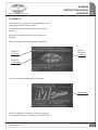
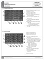
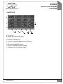
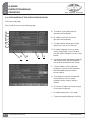
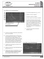
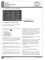
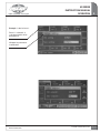
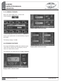
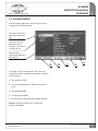
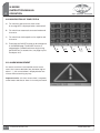
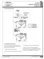
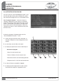
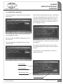
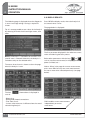
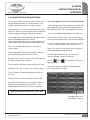
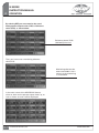
M SERIES
I Temperature Controller
Instruction Manual
M SERIES
INSTRUCTION MANUAL
TABLE OF CONTENTS
1 INTRODUCTION
1.1 MAIN FUNCTION
1.2MAIN FEATURES OF VARIOUS CABINET CONFIGURATIONS
1.3 Power Output
1.4 Tolerance on Supply Power
1.5 Maximum Power Consumed Depending on Cabinet Configuration 1.6 Maximum Allowable Current Depending on Cabinet Configuration
1.7 Cabinet Classes
Pg. 3
Pg. 4
Pg. 5
Pg. 5
Pg. 5
Pg. 5
Pg. 5
1.8
Pg. 6
Pg. 6
Pg. 6
Pg. 6
Pg. 6
MAIN FEATURES OF POWER CONTROL CARDS
1.9 Plant Power Supply
1.10 Tolerance on Plant Power Supply
1.11 Maximum Consumed Power
1.12 Nominal Frequency
1.13MAIN FEATURES OF THERMOCOUPLE INPUT CARD
1.14 Plant Power Supply
Pg. 6
Pg. 6
1.15CONNECTION TO PLANT POWER SUPPLY
1.16 INSTALLATION CONDITIONS
1.17DEFINITION OF APPLICABLE EMC STANDARDS
Pg. 6
Pg. 6
Pg. 6
2 OPERATION
2.1 General Diagram
2.2 Electronic Diagram of 16A Power Control Card
2.3 Electronic Diagram of 5A Power Control Card
2.4 Electric Power Diagram for Cabinet M4U-16.00
2.5 Electric Diagram for Commands on Cabinet M4U-16.00
2.6 Safety Conditions
2.7 Thermocouples
2.8 Power Outputs
2.9 Alarms and Setpoint Changes
2.10 Euromap 17 Communication
2.11OPERATOR INTERFACE
2.12 Start-up
2.13 Temperature Page
2.14 Status Page
2.15 Mode Page
2.16 Explanation of the Various Displayed Pages
Pg. 7
Pg. 8
Pg. 9
Pg. 10
Pg. 11
Pg. 12
Pg. 12
Pg. 13
Pg. 13
Pg. 13
Pg. 14
Pg. 15
Pg. 16
Pg. 16
Pg. 17
Pg. 18
2.17 CONFIGURATION OF CONTROL PARAMETERS
2.18 Parameters of Control Zones
2.19 Locking Keyboard
2.20 Zooming on Zones
2.21 File Management
2.22 Modification of Zone Status
2.23 Alarm Management
Pg. 20
Pg. 20
Pg. 22
Pg. 22
Pg. 23
Pg. 24
Pg. 24
2.24MOLD SCAN OPTION
Pg. 25
www.incoe.com
©INCOE® CORPORATION 8/2010
Pg. 1
M SERIES
INSTRUCTION MANUAL
TABLE OF CONTENTS
2.25 Connecting Diagram
2.26 Activation of Mold Scan 28 to 29
2.27 Start Mold Analysis
2.28 Display Results
2.29 Power Percentage Monitoring
2.30 Display Alarms
2.31 Display Curves
2.32Operating Mode for Replacing a 16A Control Card
2.33Operating Mode for Replacing a 5A Control Card
2.34Operating Mode for Replacing a Thermocouple Input Card
2.35List of Spare Parts
Pg. 25
Pg. 26
Pg. 27
Pg. 28
Pg. 29
Pg. 31
Pg. 31
Pg. 32
Pg. 32
Pg. 33
Pg. 34
3 TROUBLESHOOTING
3.1 Table of Possible Faults
Pg. 35
4 WARRANTY
4.1 General Terms and Condition of Sale
Pg. 39
5 CONTACT
5.1 Global Service
5.2 Global Offices
Pg. 41
Pg. 42
Pg. 2
© INCOE® CORPORATION 8/2010
www.incoe.com
M SERIES
INSTRUCTION MANUAL
INTRODUCTION
1
1 INTRODUCTION
The M Series of temperature controllers are designed
for precision control of the hot runner system at
constant temperature for optimized efficiency.
This new generation of hot runner control systems
uses one single microprocessor for controlling up to
24 zones, making all configurations compact.
M Series controllers are ideally suited for mid to high
volume molding requiring 16 to 128 zones.
The control over 24 zones is managed by one single
microprocessor communicating with modular
control cards having the following function:
1.1 Main Function
This range of M Series controllers is dedicated to
applications with a high number of zones to be
controlled.
www.incoe.com
- Card for data acquisition from a control loop.
- Power control card 16A or 5A for a control loop.
©INCOE® CORPORATION 8/2010
Pg. 3
1
M SERIES
INSTRUCTION MANUAL
INTRODUCTION
1.2 CABINET CONFIGURATIONS
Cabinets are submitted to EC 73/23 Directive known
as “Low Voltage” and conform to EN 61010-1
Standards.
Each cabinet is equipped with a supply cable sized
according to the maximum admissible current.
• Voltage in three phases either in 230V or 400V with
Neutral.
• Maximum allowable current: depends on diameter
and length of supply cable.
IMPORTANT NOTICE: If neutral is involved (Mainly
for Europe market), during softstart the current value
on neutral may exceed current value on one of the
three phases.
This overcurrent is controlled by the main circuit
breaker on backside of the cabinet.
The power consumed depends on the power of the
heating elements and on the number of control loops.
Dimensions of 4U cabinet:
Height:
8.50” (216mm)
Width:
21 “ (534mm)
Depth:
18.50” (470mm)
Other stickers show:
Weight of 4U cabinet:
Empty:16.9 Lbs (7,7 Kg) or with 16 power control
cards 16A: 52.6 Lbs (25,3 Kg)
- Wiring diagram of heating elements.
- Wiring diagram of thermocouples.
It is required to conform with wiring information.
Dimensions of 9U cabinet:
Height:
17.16” (436mm)
Width:
21 “ (534mm)
Depth:
18.50” (470mm)
Weight of 9U cabinet:
Empty:28.4 Lbs (12,9 Kg) or with 32 power control
cards 16A: 105.8 Lbs (48,1 Kg)
A sticker is affixed on backside of cabinet showing:
• Serial number: to identify when the cabinet was
built (eg: 01220B stands for 20th December 2000, B
is an index).
• Type: cabinet designation (M4U-16.00: 16 zones 16A).
• Frequency : all cabinets are designed for use either
in 50 or 60 Hz.
Pg. 4
© INCOE® CORPORATION 8/2010
www.incoe.com
M SERIES
INSTRUCTION MANUAL
INTRODUCTION
1.3 Power Output
230V 3 Phases 60 Hz or 400V 3 Phases + Neutral 50
Hz when required.
The choice is made when ordering the cabinet
(see below).
2
1.6 Maximum admissible current per
cabinet configuration
Cabinet M4U-16.00: 63A
Cabinet M4U-08.08: 63A
Cabinet M4U-00.16: 40A
1.4 Tolerances on supply voltage
Cabinet M4U-00.24: 40A
207V to 253V, or 360V to 440V when applied.
Cabinet M9U-00.32: 40A
1.5 Maximum consumed power per
cabinet configuration
Cabinet M9U-00.48: 40A
Cabinet M9U-24.00: 100A
Cabinet M4U-16.00: 16 x 3600W = 57600W.
Cabinet M9U-32.00: 125A
Cabinet M4U-08.08: 8 x 3600W + 8 x 1000W = 36800W.
Cabinet M9U-08.16: 63A
Cabinet M4U-00.16: 16 x 1000W = 16000W.
Cabinet M9U-08.24: 63A
Cabinet M4U-00.24: 24 x 1000W = 24000W.
Cabinet M9U-08.32: 63A
Cabinet M9U-00.32: 32 x 1000W = 32000W.
Cabinet M9U-00.48: 48 x 1000W = 48000W.
1.7 Cabinet class
Cabinet M9U-24.00: 24 x 3600W = 86400W.
Classe III according to EN 61010-1 standards.
Cabinet M9U-32.00: 32 x 3600W = 115200W.
Cabinet M9U-08.16: 8 x 3600W + 16 x 1000W = 44800W.
Cabinet M9U-08.24: 8 x 3600W + 24 x 1000W = 52800W.
Cabinet M9U-08.32: 8 x 3600W + 32 x 1000W = 60800W.
www.incoe.com
©INCOE® CORPORATION 8/2010
Pg. 5
1
M SERIES
INSTRUCTION MANUAL
INTRODUCTION
1.8 MAIN FEATURES OF POWER CONTROL CARDS
1.14 Power supply
12V DC.
Power control cards are submitted to the EC 73/23
Directive known as “Low Voltage” and conform to EN
61010-1 standards.
1.15 CONNECTION TO PLANT POWER
Length:3.74” (95 mm)
Controllers should be grounded to a suitable ground.
It is required to conform to wiring diagrams for
preventing any serious damage caused to the
cabinet.
CAUTION: (NOT REQUIRED in US) When supplied
in 400V, neutral wiring is required otherwise
safety function is impossible. The safety circuit on
synchronization card will trip the circuit breaker.
Width: 2.16” (55 mm)
1.16 INSTALLATION
Weight of 16A power control card: < 0.1 lbs (64 g)
Installation in dry industrial conditions.
Window for service temperature: from 14°F to 140°F.
Depending on cabinet configuration, two types of
power control cards that can be integrated in M
Series cabinets: 16A power control card (3600W) and
5A power control card (1000W).
Dimensions of 16A power control card:
1.9 Plant power supply
230V single phase.
Take care when unpacking / moving the controller
1.10 Tolerances on power supply
1.17 DEFINITION OF CEM APPLICABLE
STANDARDS
207V to 253V
1.11 Maximum consumed power
Standard on emission in industrial environment:
EN 50081-2
For 16A power control card: 3600W.
For 5A power control card: 1000W.
Standard on immunity in industrial environment:
EN 50082-2
1.12 Frequency
50Hz to 60Hz.
1.13 MAIN FEATURES ON THERMOCOUPLE
INPUT CARDS
Cards for thermocouples are submitted to the EC
73/23 Directive known as “Low Voltage” and conform
to EN 61010-1 standards.
Dimensions of thermocouple input card:
Length:80 mm
Width: 42 mm
Weight of thermocouple input card: 0,022 Kgs
Pg. 6
© INCOE® CORPORATION 8/2010
www.incoe.com
M SERIES
INSTRUCTION MANUAL
OPERATION
2
2 OPERATION
2.1 Overall diagram
www.incoe.com
©INCOE® CORPORATION 8/2010
Pg. 7
2
M SERIES
INSTRUCTION MANUAL
OPERATION
2.2 Electronic diagram of power control card 16A
Pg. 8
© INCOE® CORPORATION 8/2010
www.incoe.com
M SERIES
INSTRUCTION MANUAL
OPERATION
2
2.3 Electronic diagram of power control card 5A
www.incoe.com
©INCOE® CORPORATION 8/2010
Pg. 9
2
M SERIES
INSTRUCTION MANUAL
OPERATION
2.4 Electrical diagram for power on cabinet M4U-16.00
Pg. 10
© INCOE® CORPORATION 8/2010
www.incoe.com
M SERIES
INSTRUCTION MANUAL
OPERATION
2
2.5 Electrical diagram for commands on cabinet M4U-16.00
www.incoe.com
©INCOE® CORPORATION 8/2010
Pg. 11
2
M SERIES
INSTRUCTION MANUAL
OPERATION
2.6 Safety conditions
M Series cabinets are fitted with:
- American standard:
Iron: White / Constantan: Red
- circuit breaker for tool protection.
- electronic circuit for monitoring of voltage for
device protection against faulty and overvoltage
(10% of extra power is admissible).
- Venting, filter (must be cleaned frequently to
prevent damage).
‘’+’’ is Iron and can easily be identified with a
magnet.
K sensors (+ = Chrome or Nickel-Chrome, = Alumel or Nickel-Aluminium):
- French standard :
Chromel: Yellow / Alumel: Blue
Each power control card 16A or 5A is protected by:
- The power control card is protected if supply
voltage exceeds 275 V.
- Quick blown fuses on all phases and neutral protect
the TRIAC against overcurrent draw.
2.7 Thermocouples
Temperature sensors are connected on the male
HARTING plug (in case of a non-mixed wiring
diagram) located on backside of cabinet. Thermocouples
of J type (Iron-Constantan), or K (Ni.Cr/NiAL), or
auxiliary inputs can be connected. Conform to
polarity diagram as indicated on the wiring diagram.
Some standards define colours for thermocouple
leads, for instance:
- German standard:
Chromel: Red / Alumel: Green
- British standard:
Chromel: Red/ Alumel: Blue
- European standard:
Chromel: Green / Alumel: White
- American standard:
Chromel: Yellow/ Alumel: Red
Wires between J or K thermocouples and connectors
on backside of cabinet must made of the same metal
as the sensor (compensation leads) in order not to
introduce parasite thermocouples.
Wiring diagram according to INCOE standard:
J sensors (+ = Iron, - = Constantan):
- French standard:
Iron: Yellow / Constantan: Black
- German standard:
Iron: Red/ Constantan: Blue
- British standard:
Iron : Yellow / Constantan: Blue
Base for Thermocouple 48 pins 16A
Type HARTING HAN E WITH MALE INSERT.
- European standard:
Iron: Black / Constantan: White
Pg. 12
© INCOE® CORPORATION 8/2010
www.incoe.com
M SERIES
INSTRUCTION MANUAL
OPERATION
2
2.8 Power output
For 16A and 5A power control cards, heaters are
connected to a female HARTING HAN E 24 pins 16A
connector.
Wiring diagram according to INCOE standard:
A sticker is affixed on the upper cover of the cabinet
(version 4U) or on backside of cabinet (version 9U
and superior):
2.10 Communication according to
EUROMAP 17 protocol
Base Power 48 pins 16A
Type HARTING HAN E WITH FEMALE INSERT.
Each zone Nbr. (or control card) must match with
the same number for thermocouple and heating
element.
INCOE® cables for thermocouples and power have
specific features to prevent wrong orientation of plug
/ receptacle inserts.
4 pins connectors male and female located on
backside of cabinet enable the connection of an M
Series cabinet to an injection molding machine or
with a computer for data exchange according to the
EUROMAP 17 protocol.
CAUTION:
Respect polarity on wires BC+ et BC-.
2.9 Alarms and setpoint switches
It is possible to remotely switch from service setpoint
to standby setpoint and vice-versa over a switch
connected between pins 1 and 4 of the connector
2nd SETPOINT AND ALARMS.
Contact closed = 2nd setpoint.
Contact open = 1st setpoint.
It is possible to activate a sound or visual alarm
(buzzer, flashlight…) from the same connector.
- for deviation high: switch between pins 5 and 2.
- for deviation low: switch between pins 6 and 3.
www.incoe.com
©INCOE® CORPORATION 8/2010
Pg. 13
2
M SERIES
INSTRUCTION MANUAL
OPERATION
2.11 OPERATOR INTERFACE
LCD Display
Direction arrows
and Enter key
Explanation of
program icons
These keys are for accessing functions as defined on
the LCD screen.
Enter key and key for zone selection. Keep it pressed
for 2 seconds for selecting all zones or a group of
zones.
In case zone groups have been defined, press this
key to apply a new function to all zones in this
group.
Escape key.
Key to delete an input completely or partially.
Alphanumeric keyboard for inputs.
Pg. 14
© INCOE® CORPORATION 8/2010
www.incoe.com
M SERIES
INSTRUCTION MANUAL
OPERATION
2
2.12 START UP
Connect power supply cable to an appropriate power
supply (See sticker on the backside).
Check thoroughly the wiring going to and from the
cabinet.
Switch on the cabinet with the circuit breaker on
backside.
After 10 seconds, the following page is displayed:
Serial No.
of cabinet
Program
release No.
inside CPU
Serial No.
of CPU board
Then a second intermediate page is displayed:
Cabinet type
After this introduction sequence, you may visualize 3
main pages with successive pushes on the NEXT key.
www.incoe.com
©INCOE® CORPORATION 8/2010
Pg. 15
M SERIES
INSTRUCTION MANUAL
OPERATION
2
2.13 Temperature page
A
A:
B:
C:
D:
E:
Actual temperature value in °C or °F.
Setpoint in °C or °F.
Decrease setpoint value.
Increase setpoint value.
To access the page for configuring
control parameters.
F: To access page for parameters of
control zones.
G: To access next page (Status page and
Mode page)
H: Means that no reading of actual value is possible:
THI (thermocouple reversed) or
THC (thermocouple broken)
I: Zone label (configurable). Name of
the zone
I
B
H
C
D
E
G
F
2.14 Status page
A
K
B
J
C
I
D
Pg. 16
© INCOE® CORPORATION 8/2010
E
F
G
H
A:
B:
C:
D:
Zone with deviation low.
Zone with deviation high.
Zone in normal function.
To access the page for system
parameters.
E: To lock or unlock the keyboard with a password. (Please note that when a PC
running WIN’COM 2000 is connected,
the cabinet keyboard is deactivated).
F: Select display mode: Zoom 1 zone among 16.
Zoom 2 zones among 16.
Zoom 4 zones among 16.
G: To access the page for file
management
H: To access next page (Mode page).
I: Zone switched off.
J: Thermocouple broken (or
reversed).
K: Zone in soft start.
www.incoe.com
M SERIES
INSTRUCTION MANUAL
OPERATION
2
2.15 Mode page
A
I
B
C
D
E
F
G
H
A:1st setpoint.
B:Control zone in automatic mode.
C:Control zone in manual mode.
D:To switch a zone on or off.
E: To switch a zone from automatic to manual mode.
F: To switch from 1st setpoint to 2nd setpoint.
G: To activate the BOOST function.
H: To access next page (Temperature page).
I: Indicates the zone is in BOOST mode.
www.incoe.com
©INCOE® CORPORATION 8/2010
Pg. 17
2
M SERIES
INSTRUCTION MANUAL
OPERATION
2.16EXPLANATION OF THE VARIOUS DISPLAY PAGES
(From the mode page)
Press CONFIG to access the following page:
A: To modify system date (with the
alphanumeric keyboard).
A
B
C
D
E
F
B: To modify system time (with the
alphanumeric keyboard).
C: To read ambient temperature inside
cabinet via a sensor on CPU card.
G
H
I
J
D: To modify language. You may select
among 5 languages : French, English,
German, Italian and Spanish (see screen
below).
E: To select the screen displayed permanently
and automatically after the keyboard
has not been touched for one minute.
F: To enter address of the cabinet for
Euromap 17 communication between
WIN’COM 2000 software and the
control cabinet.
G: To change password for locking and
unlocking access to the system.
Important notice: factory setting is
123456.
H: To restore all cabinet and zone settings
as they were at delivery.
I: To modify parameters in this page.
J: To move to page configuration 2 (CFG2).
Pg. 18
© INCOE® CORPORATION 8/2010
www.incoe.com
M SERIES
INSTRUCTION MANUAL
OPERATION
2
Press CGF2 to access the following page:
A
B
C
D
E
F
A: To select the temperature unit (°C or °F).
B: To define a minimum setpoint.
C: To define a maximum setpoint.
D: To select a type of sensor (type J or type K).
Key to select parameters
to be modified
E: To allow the automatic switch to manual
mode in case of thermocouple breakage. If
so, the last percentage of power calculated
by the CPU is applied to the zones with
broken sensors. If not, the power is cut and
the zone remains in automatic mode.
Press NEXT to access the second page for
configuration:
F: To enter the password to activate the
MoldScan option.
A: To select the softstart mode: either ramp duration
(RT) or ramp rate (RR).
B: To select ramp duration with unit °F/minute (if
selected before).The temperature is raised every
minute by a preset number of degrees. The
percentage of power applied is not limited. When
actual temperature reaches setpoint, the ramp is
over. Its duration depends on the gap between
setpoint and actual temperature value as well as
the temperature increase per minute selected.
Press CGF3 to access the following page:
C: To define the ramp duration in minutes (if this
mode was selected).
D: To define the maximum power applied during the
softstart phase (in %).
E: To define the duration of the BOOST function (in
seconds).The principle of the BOOST function
is to increase or decrease setpoint of all zones
during a programmable period of time.
www.incoe.com
©INCOE® CORPORATION 8/2010
Pg. 19
2
M SERIES
INSTRUCTION MANUAL
OPERATION
2.17 CONFIGURATION OF CONTROL PARAMETERS
Keys to scroll in parameters
in both directions
2.18 Parameters of control zones
Still from the temperature page, press the PARAM
key to access the following page:
From this page, you may select several parameters
by pressing the key:
- Active setpoint
- 1st setpoint AUTO (°F)
- 2nd setpoint AUTO (°F)
- 1st setpoint MANU (%)
- 2nd setpoint MANU (%)
- BOOST value (°F): this is the value in °F by which
the setpoint will be increased or decreased on one or
more selected zones during a programmable period
of time. Adjustable from 0 to 500°C (or °C).
- Deviation high (°F): Adjustment of acceptable
deviation above setpoint. Adjustable from 0 to 500°C
(or °C).
- Deviation low (°F): Adjustment of acceptable
deviation below setpoint. Adjustable from 0 to 500°C
(or °C).
- Zone slaving: in case of broken or faulty thermocouple,
you may use the temperature value from another
neighboring zone for control. This prevents an
immediate action on the tool. Select the faulty zone
when the parameter “zone slaving” is shown. Press
MODIF and select with the direction arrows the
required zone for troubleshooting.
- Power applied (%): to display instant power value
applied to each heating element.
- Other parameters: after entering password (factory
setting 123456) to display and/or modify other
control parameters such as control mode (PID or
manual), gain …..etc. (Should only be accessed
by INCOE personnel or maintenance dept when
necessary).
To modify above mentioned parameters, simply
press the MODIF key.
- Zone number and description: for naming zones.
Then a window for parameter modification is
displayed:
- Zones regrouping: to gather several zones into a
group. You may group by manifolds or nozzles and
manage group 1 and group 2 eventually for other
zones.
Notice: to change setpoint, select one or more zones
and press any key on the alphanumeric keyboard,
a window then opens for setpoint modification (see
screen below). Type in new setpoint value and enter.
Pg. 20
© INCOE® CORPORATION 8/2010
www.incoe.com
M SERIES
INSTRUCTION MANUAL
OPERATION
2
Example : Label of zone 1.
Zone 1 is selected : it
is displayed with white
background
Window for parameter
modification
www.incoe.com
©INCOE® CORPORATION 8/2010
Pg. 21
2
M SERIES
INSTRUCTION MANUAL
OPERATION
2.19 Locking keyboard
Still in the status page, press to access the
following page:
Display mode 2 zones on screen
Access to the parameters can be locked by using the
password.
The factory setting is 123456.
2.20 Zooming on zones
Pressing the ZOOM key enables the selection to the
zoom level on display. You may display 1 zone, 2
zones or 4 zones on the screen:
Display mode 4 zones on screen
To change this password, please see page 18, part G.
Display mode 1 zone on screen
Pg. 22
© INCOE® CORPORATION 8/2010
www.incoe.com
M SERIES
INSTRUCTION MANUAL
OPERATION
2
2.21 File Management
From the status page, press the FILE key to access
the page for file management:
The arrow shows the
selected file from the
list
File with the white
background: the
settings in this file are
currently in use
Miscellaneous
information about the
selected file
A
B
C
D
E
This page is for file management. Each file may
contain the author, mold and part number as well as
free comments.
A: To create a new file.
B: To save new parameters under the current file
name.
C: To load selected file.
D: To cancel selected file.
E: To display main file parameters before loading.
Notice: the cabinet memory has a maximum
capacity for 16 files.
www.incoe.com
©INCOE® CORPORATION 8/2010
Pg. 23
2
M SERIES
INSTRUCTION MANUAL
OPERATION
2.22 Modification of zone status
A: To switch on and off one or more zones.
A message OFF is displayed when switched off.
B: To switch from automatic to manual mode and
vice-versa.
C: To switch from 2nd setpoint to 1st setpoint and
vice-versa.
D: To activate the BOOST function to be configured
in the PARAM page. The BOOST function is
stopped after a predefined time or by pushing
the BOOST key a second time. (see page 23 part
E and part 13.2).
A
B
C
D
E
2.23 Alarm Management
As soon as an alarm is activated on one or more
zones (for instance deviation low, deviation high or
others…..), the screen below is displayed after one
minute without touching any key:
Important notice : this icon means there is no power
to the heater and that an alarm is currently activated.
Pg. 24
© INCOE® CORPORATION 8/2010
www.incoe.com
M SERIES
INSTRUCTION MANUAL
OPERATION
2
2.24 MOLDSCAN OPTION
2.25 Connecting diagram
The aim of this option is to analyze the electric
heaters inside the tool by measuring the current
zone by zone in order to define:
- installed electrical power (in Watts).
- the temperature increase (in Degrees/Minute).
It shows all alarms (thermocouple broken or
reversed, open load ...) in a dated logbook. It also
shows in real time a diagram about the temperature
changes and the setpoint for a selected zone.
- resistance value of the heating element (in Ohms).
www.incoe.com
©INCOE® CORPORATION 8/2010
Pg. 25
2
M SERIES
INSTRUCTION MANUAL
OPERATION
2.26 Activation of MoldScan
Turn to on the line ”Activate MoldScan option” with
the left and right arrows, then validate; this is done
from the System page (CFG1) or in the MODIF menu.
Line “Automatic Analysis “: when this feature is
selected, a diagnostic on the zone(s) in automatic
mode and currently under temperature low or high
alarms is performed. A new Scan is carried out on
these zones until the alarm disappears. When not
selected, the Analysis can be started manually with
the Scan menu.
A fourth main page is displayed when the line
“Active MoldScan function “ is ON:
A
A: shows the type of control zone (16A cards or
5A cards). Depends on the configuration of the
cabinet.
B: to manually start the Scan of the tool.
C: to display all parameters for the mold Analysis.
Parameters displayed:
- Amps for each control zone.
- Power (in Watts) for each control zone.
- Resistance (in ohms) of each heating element.
- Response time (in °/min) for each control zone
B
C
D
E
F
D: to show all alarms recorded in logbook.
E: to display actual temperature for each control
zone and their setpoint in a graphical form.
Pg. 26
© INCOE® CORPORATION 8/2010
www.incoe.com
M SERIES
INSTRUCTION MANUAL
OPERATION
2
2.27 Start mold Analysis
The following page is displayed when pressing the
SCAN menu:
Select YES for “Advanced Data Analysis” and validate.
This starts a detailed Analysis of control zones and
to define all parameters described in 14.2. If you
select NO, a shorter Analysis will be carried out. All
parameters described in 14.2 except the response
time (in degree /minute).
With the direction arrows, select YES and enter to
start a MoldScan Analysis.
By pressing NO, the MoldScan diagnostic will not
be carried out.
The following page is displayed when you select
YES and enter:
The info page below is shown to confirm the start of
the Analysis:
The Analysis (advanced or not) lasts for a certain
time (depending on the number of zones inside the
cabinet).
During Analysis, data is displayed in real time in
page shown below:
Zone wattage
Zone resistance
Thermocouple status
Temp. response time
www.incoe.com
©INCOE® CORPORATION 8/2010
Pg. 27
2
M SERIES
INSTRUCTION MANUAL
OPERATION
2.28 Display results
The following page is displayed when the diagnostic
is over: A message asking if saving is required is
shown.
Press MEAS to display results when the Analysis of
the control zones is over.
The page below is displayed:
Tip: It is recommended to save values of the Analysis
by selecting YES with the left and right arrows, then
enter.
The first parameter displayed is the reference current
value saved during the Scan process.
Notice: the Analysis is carried out on all zones if no
specific zone is selected. Otherwise, the Analysis is
carried out only on the selected zones.
The status of each zone is shown on the main page
when the Analysis is over.
The icon
shown above is displayed in
case of :
- Blown fuse.
- Wrong load (heater) connections.
- Triac short circuit.
- Current value measures is different from the saved
value during Analysis.
Pg. 28
© INCOE® CORPORATION 8/2010
Select other parameters with the keys
and
such as current measurement (in Amps), applied
power (in Watts) etc….
Notice : When in the page for current measurement,
press menu DIAG to carry out a new measurement
on one or more zones selected previously (see page
below).
DIAG enables current measurement
independently on one or
more zones.
www.incoe.com
M SERIES
INSTRUCTION MANUAL
OPERATION
2
2.29 Power percentage monitoring
This function allows to obtain an alarm signal when
the percentage of power sent to the heaters in the
mold is considered as out of the normal values.
You have to give the system a reference value on each
zone. This value is a percentage of power in reference
to the average percentage of power on the zone.
The average value is refreshed every second so that an
alarm could be declared every second.
A too large variation of the percentage of power can
show an abnormal situation on the controlled zone.
Here is an example about how this monitoring
system works:
The Average power (PCA) is calculated in real-time
and refreshed every second on each zone.
Example: PCA = 45,3% on zone 1. (this value given by
the CPU changes every second)
To reset the appearing alarm, here are the possibilities:
- If the Average power (PCA) decreases by itself and
comes back into the correct values (between PCRPCS and PCR+PCS). The alarm disappears by itself.
- If you set the Monitoring tolerance to 0 (PCS = 0).
- If you switch off the system, you reset the alarms.
Be careful the average value is not memorized (PCA).
- If you change the setpoint value so that the system
is not in a normal control mode (heat up or not).
Note: This system can be switch off by setting the
monitoring tolerance to 0 (PCS = 0).
By selecting the RESU menu you can display
several parameters from this function.
Use the
and
right parameter.
function keys to select the
The user defines a Reference value (PCR) on this zone.
Example: PCR = 46% on zone 1. (this value is fixed)
You can for example display the Average power
(PCA) calculated in real-time:
The user defines a Monitoring tolerance (PCS) on
this zone.
Example: PCS = 2% on zone 1 (this value is fixed)
Each time the Average power (PCA) goes higher or
lower than the Reference value (PCR) + or – the
Monitoring tolerance (PCS), an alarm is declared:
Monitoring alarm when PCA > PCR + PCS
Average power (PCA)
calculated in real-time
www.incoe.com
©INCOE® CORPORATION 8/2010
Pg. 29
2
M SERIES
INSTRUCTION MANUAL
OPERATION
By selecting REF, you can memorize the actual
Average power output values (PCA) as Reference
values (PCR), as shown below:
Reference power (PCR)
(defined by the user)
Then, you have to set a monitoring tolerance
value (PCS)
Monitoring tolerance between 0 and 100%. If this
value is 0, the monitoring
is switched off.
In the main screen of the MOLDSCAN feature,
when an alarm on the percent output shows up, an
icon as shown on zone 4 will be displayed:
Pg. 30
© INCOE® CORPORATION 8/2010
www.incoe.com
M SERIES
INSTRUCTION MANUAL
OPERATION
2
2.30 Display alarms
2.31 Display curves
Press the ALARM key to display all alarms as
shown below:
Press menu MEAS to display actual temperature and
setpoint as a matter of time.
As shown below:
Displayed zone
Setpoint value
Actual temperature value
A: to move to the oldest or to the latest alarm
message 500 messages are stored. Alarm 501
erases alarm 1 automatically, and so on.
B: to sort alarm messages by zone number or date
and time.
C: to delete one or more preselected alarm
messages.
Notice: Alarm messages are sorted by zone number
or date and time.
Press menu CURS to position a vertical cursor as
shown below:
Maximum temperature value
Temperature increase speed
Minimum temperature value
Cursor
Press left and right arrows on the keypad to display
another control zone.
www.incoe.com
©INCOE® CORPORATION 8/2010
Pg. 31
2
M SERIES
INSTRUCTION MANUAL
OPERATION
2.32 Remove and replace a 16A control card
1)
1) Remove back cover and unscrew the 2 screws
holding the TRIAC BTA40A/700B.
Then you may pull the control card in your direction
in order to remove it from the black 6 pins connector.
DO NOT REMOVE CARD IF TRIAC HAS NOT BEEN
UNSCREWED.
Screw driver
2)
2) Hold control card in hand and remove the 2
connectors as shown. Place new card and replace
with.
2.33 Remove and replace a 5A control card
1)
1) Remove back cover and unscrew the 2 screws
holding the TRIAC BTA12A/700B.
Then you may pull the control card in your direction
in order to remove it from the black 6 pins connector.
DO NOT REMOVE CARD IF TRIAC HAS NOT BEEN
UNSCREWED.
2) Hold control card in hand and remove the 2
connectors as shown.
Screw driver
2)
Place new card and replace with.
Pg. 32
© INCOE® CORPORATION 8/2010
www.incoe.com
M SERIES
INSTRUCTION MANUAL
OPERATION
2
2.34 Remove and replace a thermocouple input card
1) Cabinet is switched off, remove front plate to access
the faulty card. Without using any tool pull the card
upwards to remove it from the 20 pins and 6 pins
Black connectors.
1)
2) Replace with new card make sure that gold plated
contacts are well located inside the 4 pins and 20
pins Black connectors.
2)
NOTE: CHECK THAT ALL
CONTACTS ARE SECURE
www.incoe.com
©INCOE® CORPORATION 8/2010
Pg. 33
M SERIES
INSTRUCTION MANUAL
OPERATION
2
2.35 List of spare parts
INCOE item
Description
Quantity
5034
16A Control card
2
4779
5A Control card
2
5095
Thermocouple input card
2
649
Fuse 16A type GRB (10 x 38 mm)
4
4472
Fuse 5FA 6.3A (5 x 20 mm)
4
5400
Fuse 5FA 2A (5 x 20 mm)
2
909
Triac BTA40A / 700B
2
5730
Triac BTA12A / 700B
2
3075
Display LCD 240 x 128 pixels
1
6438
Supply 230V / 12V-5V 40W (only in cabinet 4U)
1
6447
Supply 230V / 12V-5V 110W (from cabinet 9U)
1
6828
Ventilator 230VAC (120 x 120 x25 mm) (only in cabinet 4U)
1
2894
Ventilator 230VAC (120 x 120 x 38 mm) (From cabinet 9U)
1
Pg. 34
© INCOE® CORPORATION 8/2010
www.incoe.com
M SERIES
INSTRUCTION MANUAL
TROUBLESHOOTING
3
3.1 Table of possible faults
Fault
Effects / tool
Thermocouple
broken
Decreasing
temperature.
Display
Safeguards
Solutions
- Alarm for deviation
low activated.
- Command of TRIAC
is cut and there is no
power to the heater
-Repair break after testing
thermocouple with ohm-meter.
- Switch to manual mode if
repair is too long or if you did
not activate sensor slaving for
operating with the sensor of
another similar zone (see p21
confirm).
- The icon
is displayed to
confirm that another sensor is
used.
-Alarm for deviation
low activated.
- Repair pinched T/C
- Switch to manual mode if
repair is too long or if you did
not activate sensor slaving for
operating with the sensor of
another similar zone (see p21
confirm).
- The icon
is displayed to confirm that
another sensor is used.
- Alarm for deviation
low activated.
- Revert polarity
- Alarm for deviation
low activated.
- Check connections.
- Replace heater.
Displayed actual
temperature drops
Power indication
different from
the one normally
expected.
- Alarm for deviation
low activated.
- Percentage of
output power
increases.
- Check connections.
- Replace heater
Corresponding
power control card
is cut on faulty zone.
Symbol
- Deviation low or
high is activated.
- Fuse GRB 16A for
16A control cards
or fuse FA 6,3A for
5A control cards is
blown.
- Too high moisture : dry out
heater and replace if necessary.
- Cabinet is switched on,
remove upper cover and check
faulty fuses with LED indicators.
Cabinet is switched off, replace
fuses where the indicator was lit.
THC with alarm sign
displayed on screen.
Thermocouple
pinched
Overheating
Temperature is
constant but lower
than required
setpoint. The
deviation being low,
the following icon is
displayed:
with alarm sign
displayed on screen.
Thermocouple
reversed
Decreasing
temperature.
THI with alarm sign
displayed on screen..
Heater open
Decreasing
temperature.
The Symbol
appear on screen on
relevant zone and
alarm sign displayed
on screen
Heater partly
open
Decreasing
temperature.
Heater shorted to Decreasing
ground
temperature.
is displayed on
screen with a
blinking alarm sign.
Power applied is
increasing.
www.incoe.com
Replace with same type of fuse.
©INCOE® CORPORATION 8/2010
Pg. 35
M SERIES
INSTRUCTION MANUAL
TROUBLESHOOTING
3
Fault
Effects / tool Display
Safeguards
Solutions
Temperature
variation.
Display of actual
Actual
temperature is temperature is unstable,
symbols
unstable.
or
- Deviation low
and high are
activated.
- Problem with material to hot or
to cold.
- Problem with mold.
- Deviation low is
activated.
- Fuse GRB 16A
for 16A control
cards or fuse
FA 6,3A for 5A
control cards is
blown
- Too high moisture : dry out
heater and replace if necessary.
- Cabinet is switched on, remove
upper cover and check faulty
fuses with LED indicators.
Cabinet is switched off, replace
fuses where the indicator was lit.
Replace with same type of fuse.
are displayed
Short circuit in
heater
Temperature
is decreasing.
The corresponding
zone has alarm for low
deviation. The following
symbol is displayed:
and an alarm is
displayed. The
percentage of power
applied is increasing.
Triac shorted
Overheating
on zone
Actual temperature is
increasing drastically.
The following symbol is
displayed :
the alarm
page is displayed. The
percentage of power
applied is increasing.
-Deviation high is
activated.
Switch off cabinet immediately
Send control card for repair to
INCOE or replace faulty control
card.
- Fuse GRB 16A for
16A control cards
or fuse FA 6,3A for
5A control cards is
blown
The corresponding zone
Actual
temperature is is shown as fault on
cabinet screen.
decreasing.
- Deviation high is
activated.
- Cabinet is switched on, remove
upper cover and check faulty
fuses with LED indicators.
Cabinet is switched off, replace
fuses where the indicator remains
lit.
Replace with same type of fuse.
The zone heats
continuously
Temperature
is increasing.
- Deviation high is
activated.
- Check power value in PARAM
page.
- Check all connections as well as
heating cartridge.
- Make sure that the control card
is plugged in.
- Check thermocouple input card
by swapping card with a working
zone.
- Check cabinet fuses.
Actual temperature on
corresponding zone is
increasing steadily. The
symbol
is displayed and the
alarm sign is displayed
after one minute.
The control card
does not work
when switching the
cabinet on.
The
corresponding
heater does
not heat up
No actual temperature
value is read. The zone
shows “---” instead
of actual temperature
value.
- Deviation low is
activated.
Main switch trips
when switched on
No heater is
heating inside
the mold
The screen does not
light.
- Cabinet switched - Check supply voltage.
off.
- Check if neutral is connected if
supply is 400V 3 ph that require a
neutral.
- Check total current draw to the
mold.
Pg. 36
© INCOE® CORPORATION 8/2010
www.incoe.com
M SERIES
INSTRUCTION MANUAL
TROUBLESHOOTING
3
PROCEDURE FOR MOLD SETTERS
Example of trouble: a control zone does not reach
setpoint value.
Locate faulty zone.
Go to temperature page.
Press on menu PARAM.
Scroll in parameters with the + key until « applied
power (%)» is shown.
Or press menu ZOOM and select the faulty zone on
the wide display.
Check if the bar graph shows maximum power.
If the applied power shown equals 100% and the zone
does not heat up, 3 reasons should be investigated:
- The heating element is over dimensioned in comparison
to the power the INCOE control card can deliver and
the fuses will blow at any time. (Maximum current 16A
or 5A depending on card type).
- The power card has two fuses (one on phase, and
the second on neutral). One or both are maybe faulty
- A wire between the control card and the tool is not
connected or miswired.
The resistance may also be faulty.
For any other conditions, any service to the inside
an M Series cabinet should be carried out by authorized
personnel.
www.incoe.com
©INCOE® CORPORATION 8/2010
Pg. 37
3
M SERIES
INSTRUCTION MANUAL
TROUBLESHOOTING
PROCEDURE FOR MAINTENANCE PERSONNEL
Example of trouble : a control zone does not reach
setpoint value.
- Remove the holding bar and move the control card
upwards to remove both 20 pins and 4 pins black
connectors.
- Re-mount the holding bar.
Read page 16 to locate the faulty zone.
Then switch off the M Series cabinet with the main
circuit breaker.
Unscrew top cover and backplate (from 9U versions).
Locate faulty control card for that zone. 2 indicators
of blown fuse are fitted on this card below each fuse.
Switch on the cabinet again.
If one or two indicators light are ON, change the
corresponding fuse(s).
CAUTION: replace with the same type of fuse, i.e.
quick-blow fuses type GRB 16A (10x38mm) or type
FA 5A (5x20mm) depending on card.
If no indicator lights, then switch off the M Series
cabinet with the main circuit breaker.
Check fuses with a testing device (Ohm-meter).
Switch on the cabinet when the fuses are OK.
Check with a testing device if 230V AC (Volt/OhmMeter) is actually available on the control card
output (blue or red connectors depending on card
type). Caution ! before checking, make sure the zone
setpoint is 100% in manual mode and that all other
zones are switched OFF.
IMPORTANT NOTICE: when in function, during the
soft start phase and depending on the percentage of
power used by each control card, current value on
neutral may be higher than one of the three phase.
This overcurrent is controlled by the main circuit
breaker on backside of cabinet.
The current consumed depends on the nominal
power of the heaters and the number of control
cards utilized.
Also:
- Any work to be done inside cabinet should be
carried out by authorized personnel.
- Any component must be replaced by parts with
same specifications.
- Any work done inside the cabinet must be carried
out after complete stop procedure (except if only to
check faulty fuses thanks to LED indicators).
If 230V AC is available, the failure is not caused by
the control card.
Switch off the cabinet again with the circuit breaker.
Check electrical continuity (Ohm-Meter) between the
connectors on the control card, HARTING connectors
on backside of the cabinet and to the mold.
Pg. 38
© INCOE® CORPORATION 8/2010
www.incoe.com
M SERIES
INSTRUCTION MANUAL
WARRANTY
4
4.1 GENERAL TERMS & CONDITIONS OF SALE
1 Applicable Law and Jurisdiction
These general terms and conditions apply to all proposals and quotations submitted by Seller,
to all purchase orders received by Seller, and to all goods and services sold by Seller, except as
other-wise specifically provided in a document signed by Seller. This sale or any sale resulting
herefrom consists only of these terms and conditions and those in other documents which
are referred to herein or are attached hereto or in a document subsequently signed by Seller
and referencing this transaction (all of which constitute the “Agreement“). THE AGREEMENT
SHALL BE GOVERNED, CONSTRUED AND ENFORCED UNDER THE LAW OF THE STATE
OF MICHIGAN INCLUDING THE UNIFORM COMMERCIAL CODE IN FORCE ON THE INITIAL
DATE OF THE AGREEMENT (“UCC“), EXCEPT AS PROVIDED HEREIN. The U.N. Convention
on the International Sales of Goods shall not apply. Any services to be provided hereunder,
whether or not they are otherwise ancillary to and part of a sale of goods (as separate units), shall
be considered ancillary to a sale of goods and the UCC shall apply to all goods and services to
be provided hereunder (“Goods“). THE COURTS OF MICHIGAN SHALL HAVE EXCLUSIVE
JURISDICTION OVER THE PARTIES AND THE CLAIMS ARISING UNDER OR RELATED
TO THE AGREEMENT. The parties stipulate to the convenience of Michigan courts in general,
and Oakland Circuit Court in particular, as to all litigation. Any declaration of unenforceability
of a provision shall be as narrow as possible and shall not affect the enforceability of the other
provisions.
2 Formation, Integration and Modification
A. The Agreement supersedes all previous quotations and agreements pertaining to the Goods.
Delivery to Seller of the Buyer‘s acceptance of a Seller’s quotation (according to its terms),
Seller‘s actions in reliance on Buyer‘s oral acceptance of a written or oral quotation, or Buyer‘s
receipt of the Goods, will constitute a binding contract under the terms of the Agreement. The
Agreement is subject to Seller‘s revocation or cancellation without liability until it is approved by
Seller at its home office. Notice of such approval may be furnished to the Buyer in the form of
an acknowledgment, shipment, or other form of express approval.
B. An order submitted by Buyer orally or in a purchase order or other writing (whether or not
it contains terms or conditions modifying, adding to, repugnant to, or inconsistent with these
Terms and Conditions), may be accepted, approved or filled by Seller, but any resulting contract
and the liabilities or obligations of Seller shall be determined solely by the Agreement, and
(unless the Seller otherwise advises Buyer in writing) notice is hereby given that Seller objects
to any such terms or conditions in Buyer‘s purchase order or other writing. Seller shall not be
deemed to have in any way enlarged or modified its liabilities or obligations under the Agreement by filling such order or by failing to further object to Buyer‘s terms or conditions.
C. The Agreement is a final, complete and exclusive statement of the Agreement of the parties. THE SELLER IS WILLING TO NEGOTIATE WRITTEN CHANGES TO THESE TERMS AND
CONDITIONS, BUT RESERVES THE RIGHT TO MAKE AN ADJUSTMENT IN THE PRICE OF
THE GOODS. No modifications, limitations, waivers or discharge of the Agreement or any of its
terms shall bind Seller unless in writing and signed by Seller‘s authorized employee at its home
office. Notwithstanding anything to the contrary in this Agreement, no modifications, limitation,
waiver or discharge of any provision of the Agreement shall affect the Buyer‘s liabilities to Seller
accrued prior thereto. Seller may correct unilaterally any mathematical and typographical errors
in the Agreement. Typed provisions of the Agreement take precedence over printed provisions. A course of performance, course of dealing, or customs in the trade shall not constitute
a modification or waiver by Seller of any right by Seller.
D. The Agreement is only for the benefit of the parties, except all disclaimers and limitations
applicable to Seller shall be for the benefit of Seller‘s agents, employees, contractors, and suppliers. If any provisions are determined to apply to third parties, all other provisions including
limitations, waivers, and disclaimers shall also apply.
3 Prices, Payment and Risk of Loss
A. Prices contained in Seller‘s published price lists, if any, are subject to change without notice.
Prices contained in individual written quotations or proposals are firm only for a period of thirty
(30) days from the date of the quotation after which Buyer should inquire of Seller as to their
validity and request a written confirmation or revision. Prices do not include taxes and Buyer
shall pay all applicable sales or other taxes levied with respect to Goods (and replacements) and
the Agreement, unless exempt therefrom. All prices are in United States dollars. Buyer shall
pay all government fees levied on the installation and inspection of the Goods. Buyer shall pay
upon receipt all invoices rendered by Seller for any such items Seller may pay and for the Goods.
B. This Agreement is for a shipment contract and the Goods shall be delivered F.O.B. Seller‘s
dock. Whether or not Seller prepays shipping charges, risk of loss passes to Buyer upon tender
of the Goods to a carrier. Seller‘s breach of the Agreement shall not affect the passing of the
risk of loss to Buyer notwithstanding any provision of law to the contrary.
C. Seller may unilaterally increase prices to cover increased costs (plus reasonable overhead
and profit) of design, materials, and manufacturing required by changes requested by Buyer
after the date of any quotation.
D. All amounts not paid to Seller when due shall incur a carrying charge of 1.5% per month to
the extent allowed by law and otherwise at the highest written contract rate allowed by law.
E. All amounts due on installation or other event which requires the action or cooperation of
Buyer which Buyer fails to supply timely shall become due upon such failure.
4 Delivery
Shipping dates are estimates based on Seller‘s present engineering and manufacturing
capacity and scheduling, and may be revised by Seller upon receipt or scheduling of Buyer‘s
order. All shipping dates are approximate and shall be computed from the date of entry of
the order on Seller‘s books. All shipping dates are further subject to Seller‘s prompt receipt
from Buyer of a written purchase order or acceptance, letter of credit, down payment,
and other conditions as specified in the Agreement, and of all drawings, information and
approvals necessary to provide Goods and to grant any credit proposed in the Agreement.
www.incoe.com
5 Delay of Shipment or Performance Excused for Various Reasons
A. If shipment of any item or other performance by Seller is delayed at the request of or due
to the fault of Buyer, Seller may at its option hold the item at the place of manufacture at
the risk and expense of the Buyer from the time it is ready for shipment. In the event of any
such delay in shipment, full and final payment for an item shall be due and payable thirty (30)
days after the Buyer is notified that the item is ready for shipment. If the Seller is unwilling to
accommodate the Buyer by holding such item, the Buyer shall accept shipment immediately.
B. Dates for Seller‘s performance are estimates only. In addition, the Seller shall not be in default
because of its delay or failure to deliver or perform resulting, in whole or in part, from: (i) any
foreign or domestic embargoes, seizures, acts of God, insurrections, war, or the adoption or
enactment of any law, ordinance, regulation, ruling or order, or (ii) the lack of usual means
or transportation, fires, floods, explosions, strikes or any other accidents, contingencies, or
events, at the Seller‘s or its supplier‘s plant or elsewhere (whether or not beyond the Seller‘s
control) which directly or indirectly interfere with, or render substantially more burdensome,
Seller‘s production, delivery, or performance.
6 Inspection, Testing and Rejection
A. If the Agreement expressly provides for Buyer‘s inspection and/or acceptance of the
Goods, Seller‘s standard test procedures conducted by Seller‘s representative shall be the
criteria for inspection and/or acceptance, unless other specific procedures have been specified in the Agreement.
B. All drawings, specifications, technical documentation, samples, prototypes and Goods
shall be deemed approved and/or accepted by Buyer if Buyer does not provide a written objection and/or rejection within seven (7) days of receipt or other reasonable time established
by Seller. Any objection and/or rejection by the Buyer must be in writing and state with specificity all defects and non-conformities upon which Buyer will rely to support its rejection.
ALL DEFECTS AND NON-CONFORMITIES WHICH ARE NOT SO SPECIFIED ARE WAIVED.
7 Installation and Start Up
All Goods shall be assembled and installed by and at the expense of the Buyer. Seller may
furnish, upon request and without additional cost or liability to Seller, written instructions for
installing, maintaining, and operating the Goods. At Buyer‘s request and cost, Seller may
furnish personnel and equipment to assist in the installation and/or start up of the Goods.
Buyer shall pay Seller its prevailing per diem rates for such personnel and equipment plus
reasonable transportation, food, lodging and other travel expenses. Buyer shall have competent supervisory, maintenance and operating personnel present when Seller‘s personnel are
performing such services.
8 Software License
The Seller grants the Buyer, for its internal use only, a non-exclusive perpetual license (“License“) of all user manuals, software programs, firmware, and storage media (“Software“)
provided by the Seller in conjunction with the Goods with which the Software is provided,
for the sole purpose of the operation of the Goods. This License terminates automatically
if Buyer is in default of its obligations. The Software may be provided in machine readable
object code only. Licensee may make and keep one copy of the object code, if provided
by Seller, for backup purposes. When making a copy, the Buyer shall reproduce all Seller‘s
copyright or patent notices in all forms originally included in the Software. Buyer shall not
make any effort to obtain or reproduce the Software‘s source code. Title and all ownership
rights to the Software remain with Seller, its licensors, or its suppliers. The Software is
the proprietary information and trade secret of the Seller or its licensors, whether or not
any portion thereof is or may be validly copyrighted or patented. The License may not be
assigned nor transferred by Buyer except as a part of a transfer of the Goods with-out the
written consent of Seller which may be withheld. The Software is provided for the Buyer‘s
internal use only and the Buyer shall maintain the confidential nature of the Software and
related materials and protect them against disclosure or improper use. Buyer shall pay all
taxes based on the Software or use of the Software, however designated or levied, except
those based on Seller‘s net income. All disclaimers and limitations applicable to the Goods
apply to the License.
9 General Express Warranties
A. Seller warrants to Buyer only, that Goods (or portions thereof manufactured by Seller) shall
be free from manufacturing defects in materials and workmanship which are discovered within
the warranty period, subject to the disclaimers and limitations of the Agreement. This is not a
warranty of performance, but a limited warranty as to the condition of the Goods at the beginning
of the warranty period. The warranty period, measured from date of shipment by Seller, shall
be: one year for hot runner systems and components (other than heaters and thermocouples);
three years for defects causing leakage for DFQ bushings; three years for cast (pro-rated) and
DF heaters; one year pro-rated for screen pacs, fast cycle bushings, and KX heaters; six months
for thermocouples; two years for temperature and valve gate controllers (reduced to six months
for electronic components); one year for quick mold change products; and 90 days for all other
Goods. The percentage of the replacement cost shall be reduced by three percent for each full
month from 90 days after the date of shipment for the cast heater warranty and by 50% and
75% at the end of six and nine months, respectively, after shipment for the screen pac, fast
cycle bushings, and KX heater warranty. Because the Goods may be subject to a wide variety
of use, installation, maintenance and cleaning, the warranty is only against such defects and not
against any other failures such as, but not limited to, those due to wear and tear, and normal
maintenance and perishable items are excluded from this warranty against defects.
B. Seller warrants to Buyer that the Goods will be as described in the Agreement in all
material respects, subject to the limitations stated herein and Seller‘s published and internal
standards; however, Seller retains the right to change the dimensions, composition, design,
performance, color and appearance of the Goods without liability if, in its judgment, the
change is non material. Seller may, in its discretion, also rely on any generally accepted
industry standards.
©INCOE® CORPORATION 8/2010
Pg. 39
M SERIES
INSTRUCTION MANUAL
WARRANTY
4
4
C. Seller‘s warranties shall apply only if the Goods: (i) have been installed, maintained, and
used in conformity with instructions furnished by Seller from time to time, if any; (ii) have
been subjected to normal use for the purpose for which Goods were designed;
(iii) have not been subjected to misuse, negligence, or accident; and, (iv) have not been
altered or repaired by persons other than Seller in any respect which, in the judgment of
Seller, adversely affects the condition or operation of the Goods.
10 Patent Express Warranties
Seller shall defend and indemnify Buyer from any claim which asserts that the Goods
or their inherent methods of operation, intrinsically, infringe any United States patent,
except as to a claim based on Buyer‘s use of the Goods as a step in an overall process or as
an element in an overall combination. Seller‘s obligation shall not apply to a claim based
on Goods or portions thereof specified, designed, or manufactured by Buyer. Buyer shall
notify Seller promptly of any assertions of patent infringement and provide Seller with assistance and information requested by Seller, or Seller shall have no further obligation to
defend or indemnify. Seller shall defend with its counsel or other counsel of its choice and
shall have the sole right, without consultation with Buyer, to take all action Seller deems
appropriate to prosecute or settle such claims. Seller‘s exclusive obligation to indemnify
as to Goods declared to infringe is limited to the acquisition of a license, the replacement
of Goods with non-infringing goods, the modification of the Goods so that they are noninfringing, or the return of the purchase price and shipping costs in exchange for the Goods,
as Seller may elect. This section states the Seller‘s entire and exclusive obligation regarding patent infringement.
11 Disclaimer and Limitation of Express Warranties
There are no express warranties other than those contained in the Agreement. Any
representations as to performance and other matters, except as contained in the
Agreement, were for illustrative purposes only and do not constitute a warranty. Whether or
not the Goods are to be used exclusively by Buyer, there shall be no third party beneficiaries
to the express warranties contained herein. Seller does not warrant any portion of the
Goods not manufactured by or not furnished by Seller (whether or not specified by Buyer),
but Seller shall assign to Buyer upon request all assignable warranties of Seller‘s suppliers related
to such Goods. All descriptions, shipping specifications and illustrations of the Goods or the
Seller and its quality and other systems and capabilities in catalogues, brochures and price
lists or otherwise provided by the Seller are intended for general guidance only and the Seller
is not responsible for any errors or omissions therein or for any loss or damage resulting
from reliance on them. Seller does not warrant that it or the Goods are in compliance with
any entity, organization or industry standards, guidelines, or procedures unless specifically
contained in the Agreement.
12 Remedy and Limitation of Seller‘s Liability
A. Defective or non-conforming Goods discovered and returned during the warranty
period shall be repaired, or replaced by Seller without any additional charge and shipped
to Buyer, FOB Seller‘s plant, for reinstallation by Buyer at its cost, subject to the terms
hereof. The warranty obligation of Seller is limited to the repair or replacement at Seller‘s
plant of any part of the Goods which Buyer shall, within the warranty period, return to
Seller, with transportation charges prepaid by Buyer, and which Seller shall determine upon
examination to be defective or not in conformity with the express warranties contained
herein. In lieu of repair or replacement, if Seller elects, Seller may, upon return of such
Goods and making a determination of non conformity or defect, keep the Goods and refund
the purchase price. Buyer‘s remedies shall be limited (even in the event of Seller‘s default of
its warranty obligations) exclusively to those provided in this section. UNDER NO CIRCUMSTANCES SHALL SELLER BE LIABLE FOR CONSEQUENTIAL OR INCIDENTAL DAMAGES. Buyer waives any causes of action or theories of liability including, but not limited
to, those arising under contract, tort, strict liability, product liability, statutes, or otherwise,
except as specifically provided by the UCC as modified and limited herein. The replacement
or repair of Goods by the Seller does not give rise to any new warranty except the warranty
period provided for herein shall be extended by the length of any period from the date the
defective or non conforming Goods are received by the Seller until the date repaired or
replacement Goods are delivered to Buyer.
B. Buyer must contact Seller requesting warranty coverage plus a return authorization
number and other instructions for the return of Goods to Seller or other instructions. If
requested by Seller, Buyer shall issue a new purchase order or amendment to Seller for
replacement parts, subject to Seller issuing a credit memo if Buyer’s claim for warranty
coverage is approved. Buyer must comply with Seller’s return instructions (including return of the Goods) within 30 days or the claim shall be deemed conclusively to have been
abandoned. Buyer is responsible for properly tagging, identifying, and packing returned
Goods. Goods returned without compliance with the above procedures shall be returned
to the sender at sender’s cost.
13 Disclaimer of Implied Warranties
THE SELLER DISCLAIMS ALL IMPLIED WARRANTIES (OTHER THAN GOOD TITLE) INCLUDING BUT NOT LIMITED TO THOSE OF FITNESS FOR A PARTICULAR PURPOSE,
MERCHANTABILITY, AND NON-INFRINGEMENT. Seller does not warrant the Goods will
comply with the requirements of any safety or environmental code or regulation of any
federal, state, municipality or other jurisdiction beyond the specific express warranties in
this Agreement.
14 Parts, Service and Training Performed by Seller
All warranty and non-warranty parts, inspection, labor, service, software, and training, if
any, provided by the Seller or its agents and contractors (including those provided under
purchase orders subsequent to the Agreement) related to the Goods are subject to all limitations and disclaimers of warranties and remedies provided in the Agreement. The Seller
may have access to the Goods during or after installation of the Goods. The Seller is not
Pg. 40
© INCOE® CORPORATION 8/2010
under any duty to inspect the Goods for any defects or any improper use or modification
of the Goods nor to correct or advise the Buyer of any such condition, use or modification,
which is observed. Any notification which may be given is voluntary and subject to all
limitations and disclaimers in the Agreement.
15 User‘s Responsibility for Safety
It is Buyer‘s or other user‘s responsibility to provide all proper dies, devices, tools, training,
and other means that may be necessary to effectively protect all personnel from serious
bodily injury which otherwise may result from the method of particular installation, use,
operation, or service of the Goods. Manuals furnished by Seller; ANSI Safety Standards;
EPA, OSHA and similar state regulations; and other sources should be used by Buyer to
insure the safe use of the Goods. If Buyer fails to comply with the obligations set forth in
this section, Buyer shall indemnify and save Seller harmless from any liability or obligation
incurred by Seller to persons injured directly or indirectly in connection with the operation
of the Goods and all warranties of Seller shall become automatically void.
16 Indemnification
Buyer shall indemnify the Seller from any and all third party claims, damages, and expenses
(including reasonable attorney fees) under theories of tort, product liability, negligence (ordinary or gross), warranty, contract, statute, or otherwise arising out of the use, storage, sale,
processing or other disposition of the Goods, supplies or materials used in connection with
the Goods, or parts manufactured with the Goods, if the action or inaction of the Buyer or
its employees, customers or agents, or the Buyer‘s design specifications, were a material
or proximate cause of injuries or damages giving rise to claims against the Seller.
17 Consequential, Incidental, and Other Damages
BUYER AND THIRD PARTIES SHALL NOT BE ENTITLED TO ANY CONSEQUENTIAL, PUNITIVE, EXEMPLARY, OR INCIDENTAL DAMAGES, AS DEFINED IN THE UCC OR OTHERWISE. This limitation shall be enforced regardless of whether Seller has defaulted
in its warranty or other obligations. Any legal inability to limit or restrict the right of the
Buyer or a third party to such damages shall not affect the right of Seller to indemnification
hereunder, and under no circumstance shall Buyer recover more than the purchase price.
18 Security Interest, Power of Attorney
In addition to any security interest granted by the UCC, the Buyer hereby grants a security interest to the Seller in all Goods and documents related thereto and proceeds
and products therefrom to secure all obligations of the Buyer to the Seller, whether or not
arising under the Agreement. Buyer shall sign financing statements evidencing the security
interest as reasonably requested by Seller, or Seller may file a copy of the Agreement or
portion thereof as a financing statement. Buyer grants Seller an irrevocable power of attorney
to sign Buyer‘s name to a financing statement if necessary or convenient to perfect Seller‘s security interest. In case of a default by Buyer, Seller may peaceably enter the premises of
the Buyer and others to repossess or render inoperable all Goods in which it has a security
interest.
19 Proprietary Information
A. Buyer acknowledges that any information disclosed to Seller has not and will not be
confidential or a trade secret unless clearly and conspicuously noted on the disclosure, or
in some other writing delivered to Seller at or prior to the time of the disclosure. Otherwise,
Seller shall be under no obligation to refrain from using in its business any information,
manufacturing processes or unpatented disclosures which may pass to it from Buyer in
the performance of the Agreement
B. All proposals, plans and other information furnished by the Seller in bidding, negotiating
and performing the Agreement, are confidential and the property of Seller and shall not be
shown or disclosed to any other bidder, and shall not be shown or disclosed to any third
party or used by Buyer except as may be necessary for the selection or use of the Goods.
C. Any invention or other information developed by Seller in the performance of the Agreement shall remain the property of Seller.
20 United States Government Regulations
The Buyer shall not engage in any transaction with respect to the Goods which violates any
statute or regulation of the United States of America.
21 Certifications
Seller certifies that any Goods produced in the United States shall be produced in compliance with all applicable requirements of Sections 6, 7 and 12 of the U.S. Fair Labor
Standards Act, and of the regulations and orders of the U.S. Department of Labor issued
under Section 14 thereof. No other certifications or waivers regarding payments to Seller‘s
suppliers or laborers are required.
22 Time for Bringing Action
Any proceeding by the Buyer for breach of the Agreement or any other right against Seller
arising from or in connection with the payment cannot be filed nor maintained unless: (i)
it is commenced within one (1) year after the cause for action has accrued; (ii) Buyer has
given timely written notice to Seller of its claim as provided herein; and (iii) Buyer deposits
the unpaid portion of the purchase price with the tribunal pending final adjudication. An
action shall accrue no later than shipment of the Goods.
#330439 (2/21/01)
www.incoe.com
M SERIES
INSTRUCTION MANUAL
GLOBAL SERVICE
5
5.1 GLOBAL SERVICE
In case of problem or for any further information,
please use the contact information below, or visit
www.incoe.com.
INCOE® North America
INCOE® China | Shanghai
Support: T: + 1 (248) 556-7790
F: + 1 (248) 556-7799
E: [email protected]
Sales & Support:
T: + 86 (21) 5818-6300
F: + 86 (21) 5818-6303
E: [email protected]
INCOE® EUROPE
INCOE® Singapore
Sales & Support:
T: + 49 (0) 6074-8907-0
F: + 49 (0) 6074-8907-310
E: [email protected]
Sales & Support:
T: + 65 (6) 515-5300
F: + 65 (6) 861-1163
E: [email protected]
INCOE® South America
INCOE® China | Dongguan
Sales & Support:
T: + 55 (11) 4538-2445
F: + 55 (11) 4524-5690
E: [email protected]
Sales & Support:
T: + 86 (769) 8535-5881
F: + 86 (769) 8542-2998
E: [email protected]
INCOE® Hong Kong
Sales & Support:
T: + 852 2790-8840
F: + 852 2790-8411
E: [email protected]
www.incoe.com
© INCOE Corporation 6/2010
PDF copies of this manual are available for download on our
website at: www.incoe.com/manuals
©INCOE® CORPORATION 8/2010
Pg. 41
M SERIES
INSTRUCTION MANUAL
GLOBAL OFFICES
5
5.2 GLOBAL OFFICES
INCOE® North America
INCOE® China | shanghai
INCOE® Corporation
1740 East Maple Road
Troy, Michigan 48083
USA
INCOE® Hotrunners (Shanghai) Co., Ltd.
399 Xuanzhong Road, Building 16
Pudong New Area
Shanghai 201314
China
Main:
T: + 1 (248) 616-0220
F: + 1 (248) 616-0225
E: [email protected]
Sales:
T: + 1 (248) 556-7770
F: + 1 (248) 616-0227
E: [email protected]
Support: T: + 1 (248) 556-7790
F: + 1 (248) 556-7799
E: [email protected]
INCOE® Europe
INCOE® International Europe
Carl-Zeiss-Straße 47
D-63322 Rödermark
Germany
Sales & Support
T: + 86 (21) 5818-6300
F: + 86 (21) 5818-6303
E: [email protected]
INCOE® CHINA | Dongguan BRANCH Office
INCOE® Hotrunners (Shanghai) Co., Ltd.
Room B, 5/F, Hao Yun Building
2nd Huan Road
Changan Town, Dongguan
Guangdong, China
Sales & Support
T: + 86 (769) 8535-5881
F: + 86 (769) 8542-2998
E: [email protected]
INCOE® Hong Kong
Sales & Support
T: + 49 (0) 6074-8907-0
F: + 49 (0) 6074-8907-310
E: [email protected]
INCOE® (H.K.) Ltd.
1205 Leader Industrial Centre
57-59 Au Pui Wan Street
Fo Tan, Shatin, N.T.
Hong Kong
INCOE® SOUTH AMERICA
INCOE® International Brasil, Ltda.
Rua Eugenio Ulhano, 335
Jardim Virginia
Itatiba, SP 13257-480
Brasil
Sales & Support
T: + 55 (11) 4538-2445
F: + 55 (11) 4524-5690
E: [email protected]
Sales & Support
T: + 852 2790-8840
F: + 852 2790-8411
E: [email protected]
INCOE® Singapore
INCOE® Singapore Pte Ltd.
8, Boon Lay Way #03-02
TradeHub 21
609964 Singapore
Singapore
Sales & Support
T: + 65 (6) 515-5300
F: + 65 (6) 861-1163
E: [email protected]
Pg. 42
© INCOE® CORPORATION 8/2010
www.incoe.com
M SERIES
INSTRUCTION MANUAL
NOTES
www.incoe.com
©INCOE® CORPORATION 8/2010
Pg. 43
M SERIES
INSTRUCTION MANUAL
NOTES
Pg. 44
© INCOE® CORPORATION 8/2010
www.incoe.com
www.incoe.com
© INCOE® CORPORATION 8/2010
printed 04/11
...