1
INSTALLATION AND
OPERATION MANUAL
ASMi-52
2/4-Wire SHDSL Modem
Version 2.8
The Access Company
ASMi-52
2/4-Wire SHDSL Modem
Version 2.8
Installation and Operation Manual
Notice
This manual contains information that is proprietary to RAD Data Communications Ltd. ("RAD").
No part of this publication may be reproduced in any form whatsoever without prior written
approval by RAD Data Communications.
Right, title and interest, all information, copyrights, patents, know-how, trade secrets and other
intellectual property or other proprietary rights relating to this manual and to the ASMi-52 and
any software components contained therein are proprietary products of RAD protected under
international copyright law and shall be and remain solely with RAD.
The ASMi-52 product name is owned by RAD. No right, license, or interest to such trademark is
granted hereunder, and you agree that no such right, license, or interest shall be asserted by
you with respect to such trademark. The RAD name, logo, logotype, and the terms EtherAccess,
TDMoIP and TDMoIP Driven, and the product names Optimux and IPmux, are registered
trademarks of RAD Data Communications Ltd. All other trademarks are the property of their
respective holders.
You shall not copy, reverse compile or reverse assemble all or any portion of the Manual or the
ASMi-52. You are prohibited from, and shall not, directly or indirectly, develop, market,
distribute, license, or sell any product that supports substantially similar functionality as the
ASMi-52, based on or derived in any way from the ASMi-52. Your undertaking in this paragraph
shall survive the termination of this Agreement.
This Agreement is effective upon your opening of the ASMi-52 package and shall continue until
terminated. RAD may terminate this Agreement upon the breach by you of any term hereof.
Upon such termination by RAD, you agree to return to RAD the ASMi-52 and all copies and
portions thereof.
For further information contact RAD at the address below or contact your local distributor.
International Headquarters
RAD Data Communications Ltd.
North America Headquarters
RAD Data Communications Inc.
24 Raoul Wallenberg Street
Tel Aviv 69719, Israel
Tel: 972-3-6458181
Fax: 972-3-6498250, 6474436
E-mail: [email protected]
900 Corporate Drive
Mahwah, NJ 07430, USA
Tel: (201) 5291100, Toll free: 1-800-4447234
Fax: (201) 5295777
E-mail: [email protected]
© 1989–2009 RAD Data Communications Ltd.
Publication No. 148-200-02/09
Limited Warranty
RAD warrants to DISTRIBUTOR that the hardware in the ASMi-52 to be delivered hereunder shall
be free of defects in material and workmanship under normal use and service for a period of
twelve (12) months following the date of shipment to DISTRIBUTOR.
If, during the warranty period, any component part of the equipment becomes defective by
reason of material or workmanship, and DISTRIBUTOR immediately notifies RAD of such defect,
RAD shall have the option to choose the appropriate corrective action: a) supply a replacement
part, or b) request return of equipment to its plant for repair, or c) perform necessary repair at
the equipment's location. In the event that RAD requests the return of equipment, each party
shall pay one-way shipping costs.
RAD shall be released from all obligations under its warranty in the event that the equipment has
been subjected to misuse, neglect, accident or improper installation, or if repairs or
modifications were made by persons other than RAD's own authorized service personnel, unless
such repairs by others were made with the written consent of RAD.
The above warranty is in lieu of all other warranties, expressed or implied. There are no
warranties which extend beyond the face hereof, including, but not limited to, warranties of
merchantability and fitness for a particular purpose, and in no event shall RAD be liable for
consequential damages.
RAD shall not be liable to any person for any special or indirect damages, including, but not
limited to, lost profits from any cause whatsoever arising from or in any way connected with the
manufacture, sale, handling, repair, maintenance or use of the ASMi-52, and in no event shall
RAD's liability exceed the purchase price of the ASMi-52.
DISTRIBUTOR shall be responsible to its customers for any and all warranties which it makes
relating to ASMi-52 and for ensuring that replacements and other adjustments required in
connection with the said warranties are satisfactory.
Software components in the ASMi-52 are provided "as is" and without warranty of any kind.
RAD disclaims all warranties including the implied warranties of merchantability and fitness for a
particular purpose. RAD shall not be liable for any loss of use, interruption of business or
indirect, special, incidental or consequential damages of any kind. In spite of the above RAD
shall do its best to provide error-free software products and shall offer free Software updates
during the warranty period under this Agreement.
RAD's cumulative liability to you or any other party for any loss or damages resulting from any
claims, demands, or actions arising out of or relating to this Agreement and the ASMi-52 shall
not exceed the sum paid to RAD for the purchase of the ASMi-52. In no event shall RAD be liable
for any indirect, incidental, consequential, special, or exemplary damages or lost profits, even if
RAD has been advised of the possibility of such damages.
This Agreement shall be construed and governed in accordance with the laws of the State of
Israel.
Product Disposal
To facilitate the reuse, recycling and other forms of recovery of waste
equipment in protecting the environment, the owner of this RAD product is
required to refrain from disposing of this product as unsorted municipal
waste at the end of its life cycle. Upon termination of the unit’s use,
customers should provide for its collection for reuse, recycling or other form
of environmentally conscientious disposal.
General Safety Instructions
The following instructions serve as a general guide for the safe installation and operation of
telecommunications products. Additional instructions, if applicable, are included inside the
manual.
Safety Symbols
This symbol may appear on the equipment or in the text. It indicates potential
safety hazards regarding product operation or maintenance to operator or service
personnel.
Warning
Danger of electric shock! Avoid any contact with the marked surface while the
product is energized or connected to outdoor telecommunication lines.
Protective ground: the marked lug or terminal should be connected to the building
protective ground bus.
Warning
Some products may be equipped with a laser diode. In such cases, a label with the
laser class and other warnings as applicable will be attached near the optical
transmitter. The laser warning symbol may be also attached.
Please observe the following precautions:
•
Before turning on the equipment, make sure that the fiber optic cable is intact
and is connected to the transmitter.
•
Do not attempt to adjust the laser drive current.
•
Do not use broken or unterminated fiber-optic cables/connectors or look
straight at the laser beam.
•
The use of optical devices with the equipment will increase eye hazard.
•
Use of controls, adjustments or performing procedures other than those
specified herein, may result in hazardous radiation exposure.
ATTENTION: The laser beam may be invisible!
In some cases, the users may insert their own SFP laser transceivers into the product. Users are
alerted that RAD cannot be held responsible for any damage that may result if non-compliant
transceivers are used. In particular, users are warned to use only agency approved products that
comply with the local laser safety regulations for Class 1 laser products.
Always observe standard safety precautions during installation, operation and maintenance of
this product. Only qualified and authorized service personnel should carry out adjustment,
maintenance or repairs to this product. No installation, adjustment, maintenance or repairs
should be performed by either the operator or the user.
Handling Energized Products
General Safety Practices
Do not touch or tamper with the power supply when the power cord is connected. Line voltages
may be present inside certain products even when the power switch (if installed) is in the OFF
position or a fuse is blown. For DC-powered products, although the voltages levels are usually
not hazardous, energy hazards may still exist.
Before working on equipment connected to power lines or telecommunication lines, remove
jewelry or any other metallic object that may come into contact with energized parts.
Unless otherwise specified, all products are intended to be grounded during normal use.
Grounding is provided by connecting the mains plug to a wall socket with a protective ground
terminal. If a ground lug is provided on the product, it should be connected to the protective
ground at all times, by a wire with a diameter of 18 AWG or wider. Rack-mounted equipment
should be mounted only in grounded racks and cabinets.
Always make the ground connection first and disconnect it last. Do not connect
telecommunication cables to ungrounded equipment. Make sure that all other cables are
disconnected before disconnecting the ground.
Connecting AC Mains
Make sure that the electrical installation complies with local codes.
Always connect the AC plug to a wall socket with a protective ground.
The maximum permissible current capability of the branch distribution circuit that supplies power
to the product is 16A. The circuit breaker in the building installation should have high breaking
capacity and must operate at short-circuit current exceeding 35A.
Always connect the power cord first to the equipment and then to the wall socket. If a power
switch is provided in the equipment, set it to the OFF position. If the power cord cannot be
readily disconnected in case of emergency, make sure that a readily accessible circuit breaker or
emergency switch is installed in the building installation.
In cases when the power distribution system is IT type, the switch must disconnect both poles
simultaneously.
Connecting DC Power
Unless otherwise specified in the manual, the DC input to the equipment is floating in reference
to the ground. Any single pole can be externally grounded.
Due to the high current capability of DC power systems, care should be taken when connecting
the DC supply to avoid short-circuits and fire hazards.
DC units should be installed in a restricted access area, i.e. an area where access is authorized
only to qualified service and maintenance personnel.
Make sure that the DC power supply is electrically isolated from any AC source and that the
installation complies with the local codes.
The maximum permissible current capability of the branch distribution circuit that supplies power
to the product is 16A. The circuit breaker in the building installation should have high breaking
capacity and must operate at short-circuit current exceeding 35A.
Before connecting the DC supply wires, ensure that power is removed from the DC circuit. Locate
the circuit breaker of the panel board that services the equipment and switch it to the OFF
position. When connecting the DC supply wires, first connect the ground wire to the
corresponding terminal, then the positive pole and last the negative pole. Switch the circuit
breaker back to the ON position.
A readily accessible disconnect device that is suitably rated and approved should be incorporated
in the building installation.
If the DC power supply is floating, the switch must disconnect both poles simultaneously.
Connecting Data and Telecommunications Cables
Data and telecommunication interfaces are classified according to their safety status.
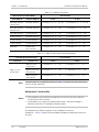
The following table lists the status of several standard interfaces. If the status of a given port
differs from the standard one, a notice will be given in the manual.
Ports
Safety Status
V.11, V.28, V.35, V.36, RS-530, X.21,
10 BaseT, 100 BaseT, Unbalanced E1,
E2, E3, STM, DS-2, DS-3, S-Interface
ISDN, Analog voice E&M
SELV
xDSL (without feeding voltage),
Balanced E1, T1, Sub E1/T1
TNV-1 Telecommunication Network Voltage-1:
Ports whose normal operating voltage is within the
limits of SELV, on which overvoltages from
telecommunications networks are possible.
FXS (Foreign Exchange Subscriber)
TNV-2 Telecommunication Network Voltage-2:
Ports whose normal operating voltage exceeds the
limits of SELV (usually up to 120 VDC or telephone
ringing voltages), on which overvoltages from
telecommunication networks are not possible. These
ports are not permitted to be directly connected to
external telephone and data lines.
FXO (Foreign Exchange Office), xDSL
(with feeding voltage), U-Interface
ISDN
TNV-3 Telecommunication Network Voltage-3:
Ports whose normal operating voltage exceeds the
limits of SELV (usually up to 120 VDC or telephone
ringing voltages), on which overvoltages from
telecommunication networks are possible.
Safety Extra Low Voltage:
Ports which do not present a safety hazard. Usually
up to 30 VAC or 60 VDC.
Always connect a given port to a port of the same safety status. If in doubt, seek the assistance
of a qualified safety engineer.
Always make sure that the equipment is grounded before connecting telecommunication cables.
Do not disconnect the ground connection before disconnecting all telecommunications cables.
Some SELV and non-SELV circuits use the same connectors. Use caution when connecting cables.
Extra caution should be exercised during thunderstorms.
When using shielded or coaxial cables, verify that there is a good ground connection at both
ends. The grounding and bonding of the ground connections should comply with the local codes.
The telecommunication wiring in the building may be damaged or present a fire hazard in case of
contact between exposed external wires and the AC power lines. In order to reduce the risk,
there are restrictions on the diameter of wires in the telecom cables, between the equipment
and the mating connectors.
Caution
To reduce the risk of fire, use only No. 26 AWG or larger telecommunication line
cords.
Attention
Pour réduire les risques s’incendie, utiliser seulement des conducteurs de
télécommunications 26 AWG ou de section supérieure.
Some ports are suitable for connection to intra-building or non-exposed wiring or cabling only. In
such cases, a notice will be given in the installation instructions.
Do not attempt to tamper with any carrier-provided equipment or connection hardware.
Electromagnetic Compatibility (EMC)
The equipment is designed and approved to comply with the electromagnetic regulations of
major regulatory bodies. The following instructions may enhance the performance of the
equipment and will provide better protection against excessive emission and better immunity
against disturbances.
A good ground connection is essential. When installing the equipment in a rack, make sure to
remove all traces of paint from the mounting points. Use suitable lock-washers and torque. If an
external grounding lug is provided, connect it to the ground bus using braided wire as short as
possible.
The equipment is designed to comply with EMC requirements when connecting it with unshielded
twisted pair (UTP) cables. However, the use of shielded wires is always recommended, especially
for high-rate data. In some cases, when unshielded wires are used, ferrite cores should be
installed on certain cables. In such cases, special instructions are provided in the manual.
Disconnect all wires which are not in permanent use, such as cables used for one-time
configuration.
The compliance of the equipment with the regulations for conducted emission on the data lines
is dependent on the cable quality. The emission is tested for UTP with 80 dB longitudinal
conversion loss (LCL).
Unless otherwise specified or described in the manual, TNV-1 and TNV-3 ports provide secondary
protection against surges on the data lines. Primary protectors should be provided in the building
installation.
The equipment is designed to provide adequate protection against electro-static discharge (ESD).
However, it is good working practice to use caution when connecting cables terminated with
plastic connectors (without a grounded metal hood, such as flat cables) to sensitive data lines.
Before connecting such cables, discharge yourself by touching ground or wear an ESD preventive
wrist strap.
FCC-15 User Information
This equipment has been tested and found to comply with the limits of the Class A digital device,
pursuant to Part 15 of the FCC rules. These limits are designed to provide reasonable protection
against harmful interference when the equipment is operated in a commercial environment. This
equipment generates, uses and can radiate radio frequency energy and, if not installed and used
in accordance with the Installation and Operation manual, may cause harmful interference to the
radio communications. Operation of this equipment in a residential area is likely to cause harmful
interference in which case the user will be required to correct the interference at his own
expense.
Canadian Emission Requirements
This Class A digital apparatus meets all the requirements of the Canadian Interference-Causing
Equipment Regulation.
Cet appareil numérique de la classe A respecte toutes les exigences du Règlement sur le matériel
brouilleur du Canada.
Warning per EN 55022 (CISPR-22)
Warning
Avertissement
Achtung
This is a class A product. In a domestic environment, this product may cause radio
interference, in which case the user will be required to take adequate measures.
Cet appareil est un appareil de Classe A. Dans un environnement résidentiel, cet
appareil peut provoquer des brouillages radioélectriques. Dans ces cas, il peut être
demandé à l’utilisateur de prendre les mesures appropriées.
Das vorliegende Gerät fällt unter die Funkstörgrenzwertklasse A. In Wohngebieten
können beim Betrieb dieses Gerätes Rundfunkströrungen auftreten, für deren
Behebung der Benutzer verantwortlich ist.
Français
Mise au rebut du produit
Afin de faciliter la réutilisation, le recyclage ainsi que d'autres formes de
récupération d'équipement mis au rebut dans le cadre de la protection de
l'environnement, il est demandé au propriétaire de ce produit RAD de ne pas
mettre ce dernier au rebut en tant que déchet municipal non trié, une fois
que le produit est arrivé en fin de cycle de vie. Le client devrait proposer des
solutions de réutilisation, de recyclage ou toute autre forme de mise au rebut
de cette unité dans un esprit de protection de l'environnement, lorsqu'il aura
fini de l'utiliser.
Instructions générales de sécurité
Les instructions suivantes servent de guide général d'installation et d'opération sécurisées des
produits de télécommunications. Des instructions supplémentaires sont éventuellement
indiquées dans le manuel.
Symboles de sécurité
Ce symbole peut apparaitre sur l'équipement ou dans le texte. Il indique des risques
potentiels de sécurité pour l'opérateur ou le personnel de service, quant à
l'opération du produit ou à sa maintenance.
Avertissement
Danger de choc électrique ! Evitez tout contact avec la surface marquée tant que le
produit est sous tension ou connecté à des lignes externes de télécommunications.
Mise à la terre de protection : la cosse ou la borne marquée devrait être connectée
à la prise de terre de protection du bâtiment.
•
Avant la mise en marche de l'équipement, assurez-vous que le câble de fibre
optique est intact et qu'il est connecté au transmetteur.
•
Ne tentez pas d'ajuster le courant de la commande laser.
•
N'utilisez pas des câbles ou connecteurs de fibre optique cassés ou sans
terminaison et n'observez pas directement un rayon laser.
•
L'usage de périphériques optiques avec l'équipement augmentera le risque pour
les yeux.
•
L'usage de contrôles, ajustages ou procédures autres que celles spécifiées ici
pourrait résulter en une dangereuse exposition aux radiations.
ATTENTION : Le rayon laser peut être invisible !
Les utilisateurs pourront, dans certains cas, insérer leurs propres émetteurs-récepteurs Laser SFP
dans le produit. Les utilisateurs sont avertis que RAD ne pourra pas être tenue responsable de
tout dommage pouvant résulter de l'utilisation d'émetteurs-récepteurs non conformes. Plus
particulièrement, les utilisateurs sont avertis de n'utiliser que des produits approuvés par
l'agence et conformes à la réglementation locale de sécurité laser pour les produits laser de
classe 1.
Respectez toujours les précautions standards de sécurité durant l'installation, l'opération et la
maintenance de ce produit. Seul le personnel de service qualifié et autorisé devrait effectuer
l'ajustage, la maintenance ou les réparations de ce produit. Aucune opération d'installation,
d'ajustage, de maintenance ou de réparation ne devrait être effectuée par l'opérateur ou
l'utilisateur.
Manipuler des produits sous tension
Règles générales de sécurité
Ne pas toucher ou altérer l'alimentation en courant lorsque le câble d'alimentation est branché.
Des tensions de lignes peuvent être présentes dans certains produits, même lorsque le
commutateur (s'il est installé) est en position OFF ou si le fusible est rompu. Pour les produits
alimentés par CC, les niveaux de tension ne sont généralement pas dangereux mais des risques
de courant peuvent toujours exister.
Avant de travailler sur un équipement connecté aux lignes de tension ou de télécommunications,
retirez vos bijoux ou tout autre objet métallique pouvant venir en contact avec les pièces sous
tension.
Sauf s'il en est autrement indiqué, tous les produits sont destinés à être mis à la terre durant
l'usage normal. La mise à la terre est fournie par la connexion de la fiche principale à une prise
murale équipée d'une borne protectrice de mise à la terre. Si une cosse de mise à la terre est
fournie avec le produit, elle devrait être connectée à tout moment à une mise à la terre de
protection par un conducteur de diamètre 18 AWG ou plus. L'équipement monté en châssis ne
devrait être monté que sur des châssis et dans des armoires mises à la terre.
Branchez toujours la mise à la terre en premier et débranchez-la en dernier. Ne branchez pas des
câbles de télécommunications à un équipement qui n'est pas mis à la terre. Assurez-vous que
tous les autres câbles sont débranchés avant de déconnecter la mise à la terre.
Français
Certains produits peuvent être équipés d'une diode laser. Dans de tels cas, une
étiquette indiquant la classe laser ainsi que d'autres avertissements, le cas échéant,
sera jointe près du transmetteur optique. Le symbole d'avertissement laser peut
aussi être joint.
Avertissement
Veuillez observer les précautions suivantes :
Français
Connexion au courant du secteur
Assurez-vous que l'installation électrique est conforme à la réglementation locale.
Branchez toujours la fiche de secteur à une prise murale équipée d'une borne protectrice de mise
à la terre.
La capacité maximale permissible en courant du circuit de distribution de la connexion alimentant
le produit est de 16A. Le coupe-circuit dans l'installation du bâtiment devrait avoir une capacité
élevée de rupture et devrait fonctionner sur courant de court-circuit dépassant 35A.
Branchez toujours le câble d'alimentation en premier à l'équipement puis à la prise murale. Si un
commutateur est fourni avec l'équipement, fixez-le en position OFF. Si le câble d'alimentation ne
peut pas être facilement débranché en cas d'urgence, assurez-vous qu'un coupe-circuit ou un
disjoncteur d'urgence facilement accessible est installé dans l'installation du bâtiment.
Le disjoncteur devrait déconnecter simultanément les deux pôles si le système de distribution de
courant est de type IT.
Connexion d'alimentation CC
Sauf s'il en est autrement spécifié dans le manuel, l'entrée CC de l'équipement est flottante par
rapport à la mise à la terre. Tout pôle doit être mis à la terre en externe.
A cause de la capacité de courant des systèmes à alimentation CC, des précautions devraient
être prises lors de la connexion de l'alimentation CC pour éviter des courts-circuits et des risques
d'incendie.
Les unités CC devraient être installées dans une zone à accès restreint, une zone où l'accès n'est
autorisé qu'au personnel qualifié de service et de maintenance.
Assurez-vous que l'alimentation CC est isolée de toute source de courant CA (secteur) et que
l'installation est conforme à la réglementation locale.
La capacité maximale permissible en courant du circuit de distribution de la connexion alimentant
le produit est de 16A. Le coupe-circuit dans l'installation du bâtiment devrait avoir une capacité
élevée de rupture et devrait fonctionner sur courant de court-circuit dépassant 35A.
Avant la connexion des câbles d'alimentation en courant CC, assurez-vous que le circuit CC n'est
pas sous tension. Localisez le coupe-circuit dans le tableau desservant l'équipement et fixez-le
en position OFF. Lors de la connexion de câbles d'alimentation CC, connectez d'abord le
conducteur de mise à la terre à la borne correspondante, puis le pôle positif et en dernier, le
pôle négatif. Remettez le coupe-circuit en position ON.
Un disjoncteur facilement accessible, adapté et approuvé devrait être intégré à l'installation du
bâtiment.
Le disjoncteur devrait déconnecter simultanément les deux pôles si l'alimentation en courant CC
est flottante.
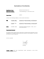
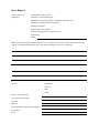
Declaration of Conformity
Manufacturer's Name:
RAD Data Communications Ltd.
Manufacturer's Address:
24 Raoul Wallenberg St., Tel Aviv 69719, Israel
declares that the product:
Product Name:
ASMi-52
conforms to the following standard(s) or other normative document(s):
EMC:
Safety:
EN 55022:1998 +
A1:2000, A2:2003
Information technology equipment – Radio disturbance
characteristics – Limits and methods of measurement.
EN 55024:1998 +
A2:2003
Information technology equipment – Immunity A1:2001,
characteristics – Limits and methods of measurement.
EN 60950-1:2001
Information technology equipment – Safety – Part 1:
General requirements.
Supplementary Information:
The product herewith complies with the requirements of the EMC Directive 89/336/EEC, the Low
Voltage Directive 73/23/EEC and the R&TTE Directive 99/5/EC for wired equipment. The product
was tested in a typical configuration.
Tel Aviv, 3 July 2005
Haim Karshen
VP Quality
European Contact: RAD Data
Ottobrunn-Riemerling, Germany
Communications
GmbH,
Otto-Hahn-Str.
28-30,
85521
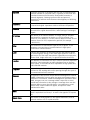
Glossary
Address
A coded representation of the origin or destination of data.
Agent
In SNMP, this refers to the managed system.
Analog
A continuous wave or signal (such as human voice).
Analog Loopback
A testing technique that isolates faults in transmission equipment
by performing a loopback on the data at the analog (line) side of
the modem.
Attenuation
Signal power loss through equipment, lines or other transmission
devices. Measured in decibels.
AWG
The American Wire Gauge System, which specifies wire width.
Balanced
A transmission line in which voltages on the two conductors are
equal in magnitude, but opposite in polarity, with respect to
ground.
Bandwidth
The range of frequencies passing through a given circuit. The
greater the bandwidth, the more information can be sent through
the circuit in a given amount of time.
Baud
Unit of signaling speed equivalent to the number of discrete
conditions or events per second. If each signal event represents
only one bit condition, baud rate equals bps (bits per second).
Bipolar
Signaling method in E1/T1 representing a binary “1” by alternating
positive and negative pulses, and a binary “0” by absence of
pulses.
Bit
The smallest unit of information in a binary system. Represents
either a one or zero (“1” or “0”).
bps (Bits Per Second)
A measure of data transmission rate in serial transmission.
Bridge
A device interconnecting local area networks at the OSI data link
layer, filtering and forwarding frames according to media access
control (MAC) addresses.
Buffer
A storage device. Commonly used to compensate for differences
in data rates or event timing when transmitting from one device to
another. Also used to remove jitter.
Bus
A transmission path or channel. A bus is typically an electrical
connection with one or more conductors, where all attached
devices receive all transmissions at the same time.
Byte
A group of bits (normally 8 bits in length).
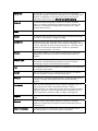
Carrier
A continuous signal at a fixed frequency that is capable of being
modulated with a second (information carrying) signal.
Cell
The 53-byte basic information unit within an ATM network. The
user traffic is segmented into cells at the source and reassembled
at the destination. An ATM cell consists of a 5-byte ATM header
and a 48-byte ATM payload, which contains the user data.
Channel
A path for electrical transmission between two or more points.
Also called a link, line, circuit or facility.
Clock
A term for the source(s) of timing signals used in synchronous
transmission.
Control Signals
Signals passing between one part of a communications system
and another (such as RTS, DTR, or DCD), as part of a mechanism
for controlling the system.
CPE (Customer Premises
Equipment)
Generally refers to communications equipment located at the
customers' premises for use with communication service providers'
services. In some cases, these are customer-owned or leased; in
other cases, these are the property of the service provider.
CRC (Cyclic Redundancy
Check)
A data transmission error-detection scheme. A polynomial
algorithm is performed on the data, and the resultant checksum is
appended at the end of the frame. The receiving equipment
performs a similar algorithm.
Current Loop
Method of data transmission. A mark (binary “1”) is represented
by current on the line, and a space (binary “0”) is represented by
the absence of current.
Data
Information represented in digital form, including voice, text,
facsimile and video.
Data Link Layer
Layer 2 of the OSI model. The entity, which establishes, maintains,
and releases data-link connections between elements in a
network. Layer 2 is concerned with the transmission of units of
information, or frames, and associated error checking.
dBm
A measure of power in communications: the decibel in reference
to one milliwatt (0 dBm = 1 milliwatt and -30 dBm = .001
milliwatt).
Decibel
See dB.
Diagnostics
The detection and isolation of a malfunction or mistake in a
communications device, network or system.
Digital
The binary (“1” or “0”) output of a computer or terminal. In data
communications, an alternating, non-continuous (pulsating) signal.
Digital Loopback
A technique for testing the digital processing of a communications
device. The loopback is toward the line side of a modem, but tests
most of the circuitry in the modem under test.
E1 Line
A 2.048 Mbps line, common in Europe, that supports thirty-two 64
kbps channels, each of which can transmit and receive data or
digitized voice. The line uses framing and signaling to achieve
synchronous and reliable transmission. The most common
configurations for E1 lines are E1 PRI, and unchannelized E1.
E3
The European standard for high speed digital transmission,
operating at 34 Mbps.
Encapsulation
Encapsulating data is a technique used by layered protocols in
which a low level protocol accepts a message from a higher level
protocol, then places it in the data portion of the lower-level
frame. The logistics of encapsulation require that packets traveling
over a physical network contain a sequence of headers.
Equalizer
A device that compensates for distortion due to signal attenuation
and propagation time with respect to frequency. It reduces the
effects of amplitude, frequency and/or phase distortion.
Ethernet
A local area network (LAN) technology which has extended into
the wide area networks. Ethernet operates at many speeds,
including data rates of 10 Mbps (Ethernet), 100 Mbps (Fast
Ethernet), 1,000 Mbps (Gigabit Ethernet), 10 Gbps, 40 Gbps, and
100 Gbps.
Flow Control
A congestion control mechanism that results in an ATM system
implementing flow control.
Frame
A logical grouping of information sent as a link-layer unit over a
transmission medium. The terms packet, datagram, segment, and
message are also used to describe logical information groupings.
Framing
At the physical and data link layers of the OSI model, bits are fit
into units called frames. Frames contain source and destination
information, flags to designate the start and end of the frame,
plus information about the integrity of the frame. All other
information, such as network protocols and the actual payload of
data, is encapsulated in a packet, which is encapsulated in the
frame.
Full Duplex
A circuit or device permitting transmission in two directions
(sending and receiving) at the same time.
FXO (Foreign Exchange
Office)
A voice interface, emulating a PBX extension, as it appears to the
CO (Central Office) for connecting a PBX extension to a
multiplexer.
FXS (Foreign Exchange
Subscriber)
A voice interface, emulating the extension interface of a PBX (or
subscriber interface of a CO) for connecting a regular telephone
set to a multiplexer.
G.703
An ITU standard for the physical and electrical characteristics of
various digital interfaces, including those at 64 kbps and 2.048
Mbps.
Gateway
Gateways are points of entrance and exit from a communications
network. Viewed as a physical entity, a gateway is that node that
translates between two otherwise incompatible networks or
network segments. Gateways perform code and protocol
conversion to facilitate traffic between data highways of differing
architecture.
Impedance
The combined effect of resistance, inductance and capacitance on
a transmitted signal. Impedance varies at different frequencies.
Interface
A shared boundary, defined by common physical interconnection
characteristics, signal characteristics, and meanings of exchanged
signals.
IP Address
Also known as an Internet address. A unique string of numbers
that identifies a computer or device on a TCP/IP network. The
format of an IP address is a 32-bit numeric address written as four
numbers from 0 to 255, separated by periods (for example,
1.0.255.123).
Jitter
The deviation of a transmission signal in time or phase. It can
introduce errors and loss of synchronization in high speed
synchronous communications.
Laser
A device that transmits an extremely narrow and coherent beam
of electromagnetic energy in the visible light spectrum. Used as a
light source for fiber optic transmission (generally more expensive,
shorter lived, single mode only, for greater distances than LED).
Loading
The addition of inductance to a line in order to minimize amplitude
distortion. Used commonly on public telephone lines to improve
voice quality, it can make the lines impassable to high speed data,
and baseband modems.
Loopback
A type of diagnostic test in which the transmitted signal is
returned to the sending device after passing through all or part of
a communications link or network.
Manager
An application that receives Simple Network Management Protocol
(SNMP) information from an agent. An agent and manager share a
database of information, called the Management Information Base
(MIB). An agent can use a message called a traps-PDU to send
unsolicited information to the manager. A manager that uses the
RADview MIB can query the RAD device, set parameters, sound
alarms when certain conditions appear, and perform other
administrative tasks.
Mark
In telecommunications, this means the presence of a signal. A
mark is equivalent to a binary 1. A mark is the opposite of a space
(0).
Master Clock
The source of timing signals (or the signals themselves) that all
network stations use for synchronization.
Multiplexer
At one end of a communications link, a device that combines
several lower speed transmission channels into a single high speed
channel. A multiplexer at the other end reverses the process.
Sometimes called a mux. See Bit Interleaving/Multiplexing.
Network
(1) An interconnected group of nodes. (2) A series of points,
nodes, or stations connected by communications channels; the
collection of equipment through which connections are made
between data stations.
Node
A point of interconnection to a network.
Packet
An ordered group of data and control signals transmitted through
a network, as a subset of a larger message.
parameters
Parameters are often called arguments, and the two words are
used interchangeably. However, some computer languages such as
C define argument to mean actual parameter (i.e., the value), and
parameter to mean formal parameter. In RAD CLI, parameter
means formal parameter, not value.
Payload
The 48-byte segment of the ATM cell containing user data. Any
adaptation of user data via the AAL will take place within the
payload.
Physical Layer
Layer 1 of the OSI model. The layer concerned with electrical,
mechanical, and handshaking procedures over the interface
connecting a device to the transmission medium.
Port
The physical interface to a computer or multiplexer, for connection
of terminals and modems.
prompt
One or more characters in a command line interface to indicate
that the computer is ready to accept typed input.
Protocol
A formal set of conventions governing the formatting and relative
timing of message exchange between two communicating
systems.
Pseudowire
Point-to-point connections set up to emulate (typically Layer 2)
native services like ATM, Frame Relay, Ethernet, TDM, or
SONET/SDH over an underlying common packet-switched network
(Ethernet, MPLS or IP) core. Pseudowires are defined by the IETF
PWE3 (pseudowire emulation edge-to-edge) working group.
Register
A storage device capable of receiving and holding a number of
digits.
Repeater
A device which automatically amplifies, restores or reshapes
signals to compensate for distortion and/or attenuation prior to
retransmission.
Serial Transmission
A common mode of transmission, where the character bits are
sent sequentially one at a time instead of in parallel.
Single Mode
Describing an optical wave-guide or fiber that is designed to
propagate light of only a single wavelength (typically 5-10 microns
in diameter).
Space
In telecommunications, the absence of a signal. Equivalent to a
binary 0.
Sync
See Synchronous Transmission.
Synchronous
Transmission
Transmission in which data bits are sent at a fixed rate, with the
transmitter and receiver synchronized.
T1
A digital transmission link with a capacity of 1.544 Mbps used in
North America. Typically channelized into 24 DS0s, each capable of
carrying a single voice conversation or data stream. Uses two pairs
of twisted pair wires.
Telnet
The virtual terminal protocol in the Internet suite of protocols. It
lets users on one host access another host and work as terminal
users of that remote host. Instead of dialing into the computer,
the user connects to it over the Internet using Telnet. When
issuing a Telnet session, it connects to the Telnet host and logs in.
The connection enables the user to work with the remote machine
as though a terminal was connected to it.
Timeslot
A portion of a serial multiplex of timeslot information dedicated to
a single channel. In E1 and T1, one timeslot typically represents
one 64 kbps channel.
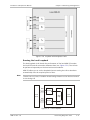
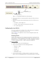
Quick Start Guide
Installation of ASMi-52 should be carried out only by an experienced technician. If
you are familiar with ASMi-52, use this guide to prepare the units for operation.
1.
Installing ASMi-52
Connecting the Interfaces
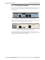
1. Connect the line to the SHDSL connector.
2. Connect the DTE to the appropriate DTE connector.
3. Connect the control terminal to the CONTROL connector.
Connecting the Power
•
Connect the AC or DC power to the ASMi-52 modem.
The unit has no power switch. Operation starts when power is connected
to the rear panel power connector.
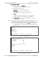
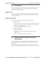
2.
Configuring ASMi-52
Configure ASMi-52 to the required operation mode via an ASCII terminal
connected to the rear panel CONTROL port directly or via a modem link.
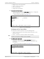
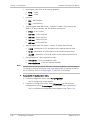
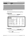
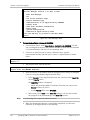
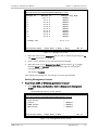
Connecting the Terminal
³
To connect the terminal:
1. Connect the terminal cable to the CONTROL connector of ASMi-52.
2. Turn the control terminal on.
3. Configure the terminal to the default communication parameters: 9.6 kbps,
one start bit, eight data bits, no parity, one stop bit.
4. Select the full-duplex mode.
5. Turn the terminal echo off.
6. Disable any type of flow control.
You are now ready to start a control session.
ASMi-52 Ver. 2.8
Configuring ASMi-52
1
Quick Start Guide
Installation and Operation Manual
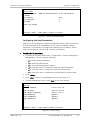
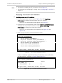
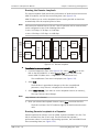
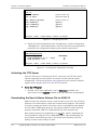
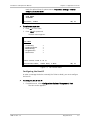
Configuring the Master Clock
³
To configure the master clock:
•
From the System Configuration menu (Main Menu > Configuration > System
Configuration > Master Clock), configure the central ASMi-52 clock to external
or internal and remote ASMi-52 clock to the receive clock.
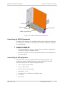
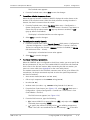
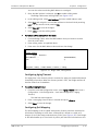
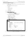
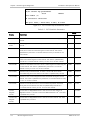
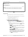
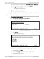
Configuring the SHDSL Interface
³
To configure the SHDSL interface:
•
From the SHDSL Configuration menu (Main Menu > Configuration > Port
Configuration > SHDSL Configuration), configure the following SHDSL
parameters:
SHDSL compatibility
Power backoff
Snext margin, if line probing is set to adaptive
Current margin, if line probing is set to adaptive
Power spectral density (for ASMi-52 with 2-wire line interface and line
probing set to fixed)
Line probing
Line type (for 4-wire ASMi-52 units only)
Loop attenuation threshold
SNR margin threshold.
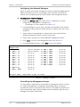
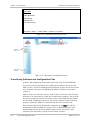
Configuring the DTE Interface
ASMi-52 includes a serial, E1, T1, or 10/100BaseT DTE interface configured as a
single interface. ASMi-52 can be multiplexed as i.e., E1 + Serial DTE interface, or
E1 + 10/100BaseT DTE interface, or Serial + 10/100BaseT DTE interface, in which
case each pair of interface has to be configured separately.
Configuring the Serial Interface
³
To configure the serial interface:
•
From the DTE Port Configuration (Main Menu > Configuration > Port
Configuration > DTE Configuration), select the required data rate.
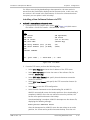
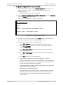
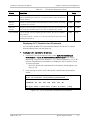
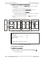
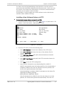
Configuring the E1 Interface
When configuring an E1 interface, you have to select the modem’s framing mode
and assign each E1 timeslot to carry data or idle code.
If in your application, an ASMi-52 unit with an E1 interface operates opposite
another ASMi-52 unit, the E1 settings of the remote device are automatically
matched to those of the local modem (the Units Identical Setting value is set to
2
Configuring ASMi-52
ASMi-52 Ver. 2.8
Installation and Operation Manual
Quick Start Guide
YES by default). The Units Identical Setting value of the local modem overrides
the management commands of the remote supervisory terminal.
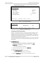
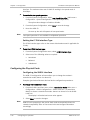
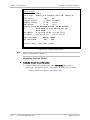
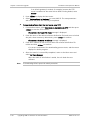
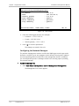
³
To configure E1 parameters:
•
Note
•
From the E1 Port Configuration menu (Main Menu > Configuration > Port
Configuration > E1 Port Configuration), configure the following E1
parameters:
Framing mode
Timeslot assignment
You can configure timeslot 0 to be looped or transparent:
Looped – timeslot 0 is sent back to the E1 interface, when operating
opposite remote units with a serial data interface.
Transparent – timeslot 0 is transmitted to the remote modem.
•
If you operate ASMi-52 with the G732S framing, timeslot 0 is always
transparent and timeslot 16 is always connected.
•
When operating a 2-wire ASMi-52 with E1 interface opposite ASMi-52 with a
serial DTE interface (not in LS mode), assign at least three timeslots,
excluding timeslot 0, to carry data.
•
When operating a 4-wire ASMi-52 with E1 interface opposite ASMi-52 with
serial DTE interface (not in LS mode), assign at least six timeslots, excluding
timeslot 0, to carry data.
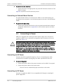
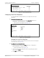
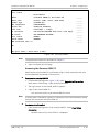
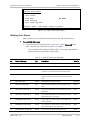
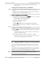
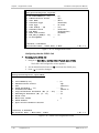
Configuring the T1 Interface
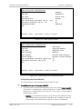
³
To configure the T1 parameters:
•
ASMi-52 Ver. 2.8
From the T1 Port Configuration menu (Main Menu > Configuration > Port
Configuration > T1 Port Configuration), configure the following T1 parameters:
Framing mode
Line coding
Receive gain
Interface type
Transmit signal mask
Timeslot assignment
Configuring ASMi-52
3
Quick Start Guide
Installation and Operation Manual
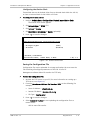
Configuring the 10/100BaseT Interface
³
To configure 10/100BaseT parameters:
•
4
From the LAN Configuration menu (Main Menu > Configuration > System
Configuration > LAN Configuration), configure the following LAN parameters:
Bridge static table
Aging timeout
LAN rate
Configuring ASMi-52
ASMi-52 Ver. 2.8
Contents
Chapter 1. Introduction
1.1
1.2
1.3
1.4
Overview.................................................................................................................... 1-1
Product Options...................................................................................................... 1-1
DTE Interface ..................................................................................................... 1-1
Line Interface ..................................................................................................... 1-2
Unit Enclosure .................................................................................................... 1-2
Applications ............................................................................................................ 1-2
Features ................................................................................................................. 1-4
Functionality ...................................................................................................... 1-4
Line Interface ..................................................................................................... 1-4
DTE Interface ..................................................................................................... 1-5
Multiplexer Functionality..................................................................................... 1-6
Timing................................................................................................................ 1-8
Management ...................................................................................................... 1-9
Diagnostics ........................................................................................................ 1-9
Statistics Collection .......................................................................................... 1-10
Alarm Reporting ............................................................................................... 1-10
SHDSL Repeaters ............................................................................................. 1-10
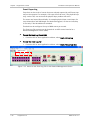
Physical Description ................................................................................................. 1-10
Functional Description.............................................................................................. 1-11
Technical Specifications............................................................................................ 1-13
Chapter 2. Installation and Setup
2.1
2.2
2.3
2.4
2.5
Site Requirements and Prerequisites .......................................................................... 2-1
Package Contents ...................................................................................................... 2-2
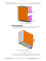
Mounting the Rail Mount Unit ..................................................................................... 2-2
Connecting the Interfaces .......................................................................................... 2-4
Connecting to SHDSL Equipment ............................................................................. 2-5
Connecting to DTE Equipment ................................................................................. 2-5
Connecting to External Alarm Devices ...................................................................... 2-6
Connecting to Power .................................................................................................. 2-6
Connecting to AC Power.......................................................................................... 2-6
Connecting to DC Power ......................................................................................... 2-6
Chapter 3. Operation
3.1
3.2
3.3
3.4
Turning On ASMi-52 ................................................................................................... 3-1
Indicators .................................................................................................................. 3-1
Front Panel Indicators ............................................................................................. 3-1
Rear Panel Indicators .............................................................................................. 3-3
Normal Indications .................................................................................................. 3-4
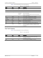
Default Settings ......................................................................................................... 3-4
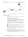
Configuration and Management Alternatives .............................................................. 3-6
Managing ASMi-52 via Ethernet Port ....................................................................... 3-7
Managing ASMi-52 via a Dedicated Timeslot ............................................................ 3-7
Working with Terminal ............................................................................................ 3-8
Control Port Interface Characteristics ................................................................. 3-8
Preparing the Terminal ....................................................................................... 3-9
Data Terminal Ready (DTR)................................................................................. 3-9
ASMi-52 Ver. 2.8
i
Table of Contents
3.5
Installation and Operation Manual
Initiating a Control Session ................................................................................. 3-9
Navigating the Management Menus .................................................................... 3-9
Correcting Entries............................................................................................... 3-9
Navigating Data Forms ..................................................................................... 3-10
Ending a Terminal Configuration Session........................................................... 3-10
Verifying the Application Software Version ....................................................... 3-10
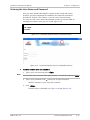
Working with Web Terminal................................................................................... 3-10
Web Browser Requirements ............................................................................. 3-10
Working with ConfiguRAD ................................................................................. 3-11
Working with RADview .......................................................................................... 3-12
Working with SNMP............................................................................................... 3-12
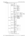
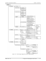
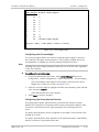
Menu Map ............................................................................................................ 3-13
Turning Off ASMi-52 ................................................................................................ 3-16
Chapter 4. Configuration
4.1
4.2
4.3
ii
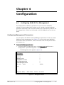
Configuring ASMi-52 for Management ........................................................................ 4-1
Configuring Management Parameters ...................................................................... 4-1
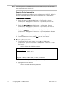
Entering Device Information ............................................................................... 4-2
Configuring the Host Parameters ........................................................................ 4-3
Configuring the Network Managers..................................................................... 4-4
Controlling the Management Access ................................................................... 4-4
Configuring Dedicated Timeslots......................................................................... 4-5
Configuring VLAN Encapsulation ......................................................................... 4-6
Configuring Control Port Parameters ....................................................................... 4-7
Changing the Control Port Data Rate .................................................................. 4-7
Selecting the Control Port Interface .................................................................... 4-8
Selecting the CTS State ...................................................................................... 4-8
Selecting the DSR State ...................................................................................... 4-8
Configuring the Terminal Port.................................................................................. 4-8
Configuring the Port Control Mode ..................................................................... 4-9
Configuring User Name, Password, Pop-up Alarms and Security Timeout ........... 4-10
Configuring for Operation ........................................................................................ 4-13
Configuring ASMi-52 System Parameters ............................................................... 4-13
Configuring the Master Clock ............................................................................ 4-14
Configuring Local/Remote Card Mode ............................................................... 4-14
Configuring Low Speed Operation .................................................................... 4-15
Setting the G.704 Interface Type ...................................................................... 4-16
Configuring the Physical Ports ............................................................................... 4-16
Configuring the SHDSL Interface ....................................................................... 4-16
Configuring the E1 Interface ............................................................................. 4-22
Matching Remote Unit Settings with Local Unit Settings ................................... 4-28
Configuring the T1 Interface ............................................................................. 4-29
Configuring the LAN Port .................................................................................. 4-31
Configuring the LAN Port Operation Mode ........................................................ 4-31
Completing the Bridging Table .......................................................................... 4-32
Configuring Aging Timeout ............................................................................... 4-33
Configuring QoS Mapping ................................................................................. 4-33
Setting the LAN Rate ........................................................................................ 4-34
Setting the LAN Rate in a Multiplexer Unit ........................................................ 4-35
Configuring Autonegotiation............................................................................. 4-36
Detecting SHDSL Link Failure ............................................................................ 4-36
Performing Additional Tasks ..................................................................................... 4-37
Displaying the ASMi-52 Status .............................................................................. 4-37
ASMi-52 Ver. 2.8
Installation and Operation Manual
Table of Contents
Displaying the System Status ........................................................................... 4-37
Displaying the Port Status ................................................................................ 4-38
Accessing the Remote ASMi-52 ........................................................................ 4-39
Displaying the ASMi-52 Inventory .......................................................................... 4-40
Entering the User Name and Password .................................................................. 4-41
Transferring Software and Configuration Files ....................................................... 4-42
Installing a New Software Release via TFTP ....................................................... 4-43
Installing a New Software Release via XMODEM ................................................ 4-44
Autoconfiguration through TFTP or XMODEM .................................................... 4-44
Displaying the Software Version ....................................................................... 4-46
Switching Software Versions ............................................................................ 4-46
Resetting ASMi-52 ................................................................................................ 4-47
Resetting to Default Settings ........................................................................... 4-47
Resetting the ASMi-52 Modem ......................................................................... 4-48
Resetting the SHDSL Repeater ......................................................................... 4-49
Chapter 5. Monitoring and Diagnostics
5.1
5.2
5.3
5.4
5.5
5.6
5.7
Monitoring Performance ............................................................................................. 5-1
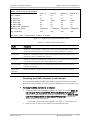
Displaying SHDSL Statistics ..................................................................................... 5-1
Displaying the Current SHDSL Statistics .............................................................. 5-1
Displaying the SHDSL Statistics for all Intervals ................................................... 5-3
Clearing the SHDSL Performance Statistics.......................................................... 5-4
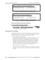
Displaying E1/T1 Statistics ...................................................................................... 5-4
Displaying the Current E1/T1 Statistics ............................................................... 5-5
Displaying E1/T1 Statistics for All Intervals .......................................................... 5-7
Clearing the E1/T1 Statistics ............................................................................... 5-8
Detecting Errors ......................................................................................................... 5-8
Power-Up Self-Test ................................................................................................. 5-8
Front Panel LEDs ..................................................................................................... 5-8
Handling Events ......................................................................................................... 5-8
Displaying All Alarms ............................................................................................... 5-9
Working with the System Log File.......................................................................... 5-10
Displaying the Port Status ..................................................................................... 5-10
Masking Port Alarms ............................................................................................. 5-11
Working with the Port Log File .............................................................................. 5-15
Handling Traps ...................................................................................................... 5-16
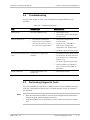
Troubleshooting ....................................................................................................... 5-17
Performing Diagnostic Tests ..................................................................................... 5-17
Running the Bit Error Rate Test (BERT) .................................................................. 5-18
Running Loopback Tests ....................................................................................... 5-20
Loopback in Multiplexer Units ........................................................................... 5-20
Running the Local Loopback ............................................................................. 5-21
Running the Remote Loopback ......................................................................... 5-23
Running Remote Loopback at a Repeater ......................................................... 5-23
Deactivating the Loopbacks .............................................................................. 5-24
Running the LEDs Test .......................................................................................... 5-25
Frequently Asked Questions ..................................................................................... 5-25
Technical Support .................................................................................................... 5-28
Chapter 6. Software Upgrade
6.1
6.2
Compatibility Requirements ........................................................................................ 6-1
Impact ....................................................................................................................... 6-1
ASMi-52 Ver. 2.8
iii
Table of Contents
6.3
6.4
6.5
6.6
Installation and Operation Manual
Software Upgrade Options ......................................................................................... 6-1
Prerequisites .............................................................................................................. 6-2
Software Files ......................................................................................................... 6-2
System Requirements ............................................................................................. 6-2
Upgrading ASMi-52 Software via the File Utilities Menu .............................................. 6-2
Verifying the ASMi-52 Host Parameters ................................................................... 6-3
Activating the TFTP Server ....................................................................................... 6-4
Downloading the New Software Release File to ASMi-52 ......................................... 6-4
Installing a New Software Release via TFTP ......................................................... 6-5
Installing a New Software Release via XMODEM .................................................. 6-6
Upgrading ASMi-52 Software via the Boot Menu ......................................................... 6-6
Using the XMODEM Protocol ................................................................................... 6-7
Using the TFTP ........................................................................................................ 6-9
Chapter 7. Application Tutorial
7.1
Equipment List ........................................................................................................... 7-1
Installing LRS-16 ..................................................................................................... 7-2
Configuring the Local LRS-16 .................................................................................. 7-4
Accessing LRS-16 ............................................................................................... 7-4
Configuring the Host IP ...................................................................................... 7-5
Configuring the Network Managers..................................................................... 7-6
Setting Management Access ............................................................................... 7-7
Configuring Terminal Parameters ........................................................................ 7-8
Setting Date and Time ........................................................................................ 7-9
Configuring Physical Layer Parameters ................................................................ 7-9
Saving the Configuration File ............................................................................ 7-11
Running Diagnostic Tests ...................................................................................... 7-12
Running Local Loopback Tests .......................................................................... 7-12
Running Remote Loopback Tests ...................................................................... 7-13
Collecting Performance Statistics .......................................................................... 7-14
Displaying Alarms ............................................................................................. 7-14
Event Reporting ............................................................................................... 7-16
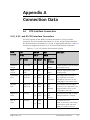
Appendix A. Connection Data
iv
ASMi-52 Ver. 2.8
Chapter 1
Introduction
1.1
Overview
ASMi-52 is an SHDSL modem that operates in full-duplex over 2/4-wire lines and
offers a cost-effective solution for delivering digital data to customer premises
over existing copper cables. ASMi-52 handles multiple data rates in the range of
64–4608 kbps. The unit is available with a single data port or as a multiplexer
with two data ports. The modem supports X.21, V.35, RS-530, E1 and T1
interfaces. In addition, ASMi-52 may contain an Ethernet/Fast Ethernet bridge
with VLAN support (via management LAN port).
ASMi-52 uses TC-PAM coding and complies with the ITU-T G.991.2 requirements,
see page 1-7.
Certain multiplexer application combinations are possible. See Table 1-4 for the
multiplexer applications.
Product Options
DTE Interface
ASMi-52 supports the following DTE interfaces:
•
X.21
•
V.35
•
RS-530
•
E1, as per G.704
•
T1
•
Ethernet/Fast Ethernet bridge with VLAN support (combined with
management LAN port)
The following combinations of interfaces can be multiplexed:
•
ASMi-52 Ver. 2.8
V.35 + LAN
Overview
1-1
Chapter 1 Introduction
Installation and Operation Manual
•
E1 + LAN
•
E1 + serial port (V.35, X.21, RS-530).
Line Interface
ASMi-52 is available for ordering in two models: for operation over a 2-wire or
4-wire lines.
Unit Enclosure
ASMi-52 is available in a plastic, metal, or rail-mount enclosure.
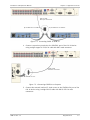
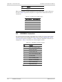
Applications
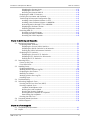
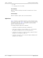
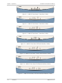
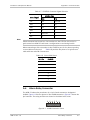
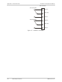
Figure 1-1 illustrates a typical ASMi-52 application, in which standalone modems
operate opposite each other. Figure 1-2 shows ASMi-52 units operating opposite
a centrally located DXC rack. Figure 1-3 shows ASMi-52 modems operating
opposite a centrally located LRS-24 rack.
The following multiplexer applications are supported:
1-2
•
A multiplexer unit opposite the same type of multiplexer unit
•
A DXC opposite multiplexer units (the multiplexer unit is a CPE), where the
DXC supports a multiplexer (the CPE is the receive clock source)
•
A multiplexer unit configured as a single unit opposite a single unit (where a
multiplexer unit is configured as a single unit)
•
A multiplexer unit opposite an E1 unit, where the single or multiplexer unit is
configured as an E1 single unit.
Overview
ASMi-52 Ver. 2.8
Installation and Operation Manual
Chapter 1 Introduction
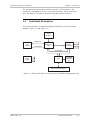
Figure 1-1. Standalone Modem Application
Figure 1-2. ASMi-52 Modems Operating Opposite a Centrally Located DXC Rack
ASMi-52 Ver. 2.8
Overview
1-3
Chapter 1 Introduction
Installation and Operation Manual
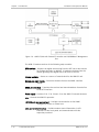
Figure 1-3. ASMi-52 Modems Operating opposite ASMi-52CD Cards
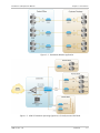
Features
Functionality
ASMi-52 can be configured to operate in a CO (central office) or CPE (customer
premises equipment) mode.
Line Interface
ASMi-52 extends the range of data transmission over 2/4-wire lines up to 7.0 km
(4.3 miles), by employing SHDSL TC-PAM technology. ASMi-52 operation complies
with the requirements of the ITU-T G.991.2 and G.826 standards. In addition,
4-wire ASMi-52 units can be configured to operate over 2-wire lines.
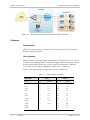
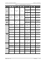
Table 1-1 lists typical ASMi-52 ranges over 2/4-wire 26 AWG line.
Table 1-1. Typical Ranges (26 AWG)
Data Rate
1-4
Overview
2-wire
4-wire
[kbps]
[km]
[miles]
[km]
[miles]
64
7.5
4.6
—
—
128
7.0
4.3
7.1
4.4
256
6.7
4.1
6.8
4.2
384
6.5
4.0
6.7
4.1
512
6.3
3.9
6.6
4.1
1024
5.3
3.3
6.0
3.7
1536
5.0
3.1
5.6
3.5
2048
4.5
2.8
4.7
2.9
2304
4.2
2.6
4.5
2.8
4096
–
–
3.7
2.3
4608
–
–
3.0
1.8
ASMi-52 Ver. 2.8
Installation and Operation Manual
Note
Chapter 1 Introduction
The typical ranges are based on error-free lab tests without noise.
ASMi-52CD/4W operates at data rates up to 4608 kbps, depending on internal or
external clock.
DTE Interface
ASMi-52 supports the following DTE interfaces:
•
X.21
•
V.35
•
RS-530
•
E1, as per G.704
•
T1
•
Ethernet/Fast Ethernet bridge with VLAN support (combined with
management LAN port).
When ASMi-52 is ordered only with the 10/100BaseT port, it can be used to
transfer user and management data.
Note
An unbalanced E1 interface is provided via an adapter cable (CBL-RJ-45/2BNC/E1).
The impedance conversion (120Ω to 75Ω) is performed by ASMi-52 automatically
when the adapter cable connection is detected.
ASMi-52 supports multiple data rates between the range of 64 kbps and
4608 kbps. The data rate depends on the following factors:
•
Unit rate mode (regular or low speed)
•
Line interface type (2-wire or 4-wire)
•
DTE interface type of the local and remote units (serial or E1/T1)
•
Clock mode (internal or external)
•
Single or multiplexed.
Table 1-2 and Table 1-3 detail the ASMi-52 data rates with the possible
combinations of rate mode types, line/DTE interface types, and clock modes.
ASMi-52 Ver. 2.8
Overview
1-5
Chapter 1 Introduction
Installation and Operation Manual
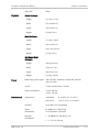
Table 1-2. ASMi-52 Data Rates
DTE Interface and Clock Mode
Local ASMi-52
Line Interface
Remote ASMi-52
2-wire
4-wire
Serial DTE interface,
internal clock
Serial DTE interface
n × 64 kbps (n = 1, 2, … 32, 36)
n × 128 kbps (n = 1, 2, …32, 36)
Serial DTE interface,
external clock
Serial DTE interface
n × 64 kbps (n = 1, 2, …, 36)
n × 128 kbps (n = 1, 2, …, 36)
Serial DTE interface
E1 DTE interface
n × 64 kbps (n = 3, 4, …, 32)
n × 128 kbps (n = 3, 4, …, 16)
E1 DTE interface
Serial DTE interface
n × 64 kbps (n = 3, 4, …, 32)
n × 128 kbps (n = 3, 4, …, 16)
E1 DTE interface
E1 DTE interface
n × 64 kbps (n = 1, 2, …, 32)
n × 64 kbps (n = 1, 2, …, 32)
T1 DTE interface
T1 DTE interface
n × 64 kbps (n = 1, 2, …, 24)
n × 64 kbps (n = 1, 2, …, 24)
Multiplexer
Serial/E1 DTE
(any) interface
n × 64 kbps (n = 1, 2, …, 32)
n × 64 kbps (n = 1, 2, …, 32)
Table 1-3. ASMi-52 Data Rates (Low Speed Mode)
Unit and DTE Interface Type
Local Unit
Remote Unit
ASMi-52 in low
speed mode
Note
Line Interface
2-wire
4-wire
ASMi-52 in low
speed mode
n × 64 kbps (n = 1, 2, …, 32)
n × 64 kbps (n = 1, 2, …, 32)
ASMi-52 with serial
DTE interface
n × 64 kbps (n = 3, 4, …, 32)
n × 128 kbps (n = 3, 4, …, 16)
ASMi-52 with E1
DTE interface
n × 64 kbps (n = 1, 2, …, 32)
n × 64 kbps (n = 1, 2, …, 32)
The data rates for a multiplexer modem in Table 1-2 include the entire data rates
sum for all the interfaces.
Multiplexer Functionality
Notes
• The multiplexer unit cannot be configured as a device with only a LAN port.
It must have a DTE or IR port.
• The hardware of a single unit-based product with a LAN port manager is
different from that of a multiplexer-based product.
The hardware has different options for the modem to work as a
multiplexer. Table 1-4 shows all the available multiplexer combinations that can
be used.
1-6
Overview
ASMi-52 Ver. 2.8
Installation and Operation Manual
Chapter 1 Introduction
Table 1-4. Possible Multiplexer Applications
CO/CPE
E1
Serial DTE
LAN
E1+Serial DTE
E1↔E1
E1
Serial DTE
LAN
E1↔E1
E1↔Serial
DTE
E1↔LAN
Serial
DTE↔LAN
E1+LAN
Serial DTE+LAN
E1↔E1
E1↔Serial
DTE
E1↔Serial
DTE
E1↔E1+Serial
DTE
E1↔E1+LAN
E1↔Serial
DTE+LAN
Serial
DTE↔E1
Serial
DTE↔E1
Serial DTE↔
Serial DTE
LAN E1
LAN Serial
DTE
E1↔E1
E1↔Serial
DTE
E1↔Serial
DTE
E1↔E1+LAN
E1↔Serial
DTE+LAN
Serial
DTE↔E1
Serial
DTE↔E1
Serial DTE↔
Serial DTE
Serial
DTE↔E1
Serial DTE↔
Serial DTE
LAN E1
LAN Serial
DTE
LAN LAN
E1↔E1
E1↔Serial
DTE
E1↔LAN
E1↔ E1+Serial
DTE
Serial
DTE↔E1
Serial DTE
↔Serial DTE
V.35↔LAN
E1↔E1
Serial DTE↔
Serial DTE
LAN E1
LAN Serial
DTE
E1+Serial
DTE↔E1
E1+Serial
DTE
Serial DTE↔
Serial DTE
E1+Serial
DTE↔E1
E1↔E1
E1+LAN↔E1
E1+LAN
E1↔Serial
DTE
E1↔LAN
E1+Serial DTE
↔E1+Serial
DTE
E1+Serial
DTE↔E1
E1↔E1+Serial
DTE
E1↔E1
E1↔Serial
DTE
E1↔Serial
DTE
E1↔E1+LAN
E1↔Serial
DTE+LAN
E1+LAN↔E1
E1+LAN↔E1
E1↔E1
E1+LAN↔
E1+LAN
ASMi-52 Ver. 2.8
Overview
1-7
Chapter 1 Introduction
CO/CPE
Installation and Operation Manual
E1
Serial DTE
LAN
Serial
DTE↔E1
Serial DTE↔
Serial DTE
Serial
DTE↔LAN
Serial DTE+
LAN↔E1
E1+Serial DTE
E1+LAN
Serial DTE+LAN
Serial
DTE↔E1
Serial DTE
↔Serial DTE
Serial
DTE↔E1
Serial DTE↔
Serial DTE
Serial
DTE+LAN
Serial DTE+
LAN↔E1
Serial DTE+
LAN↔E1
Serial DTE
+LAN↔Serial
DTE +LAN
DXC
LRS-24
Note
DXC↔E1+
Serial DTE
DXC↔E1
+LAN
DXC↔Serial
DTE+LAN
LRS-24↔
E1+Serial DTE
LRS-24↔
E1+LAN
LRS24↔Serial
DTE+LAN
Serial DTE = V.35, X.21, RS-530.
The following are multiplexer conditions when working with the ASMi-52 unit:
Note
•
E1+Serial DTE can work as an ‘E1 port only’ or a serial DTE port only.
•
E1+LAN can work as an ‘E1 port only’.
•
LAN+Serial DTE can work as a ‘Serial DTE port only’.
•
E1+Ethernet and Serial DTE+Ethernet can be configured as a single port only
(‘E1 only’ or ‘Serial DTE only’) while the Ethernet port operates as a
management port only.
ASMi-52 E1 or Serial DTE units with a LAN management port previously released
with software versions earlier than version 2.5 cannot operate as a multiplexer
unit (E1+LAN, Serial DTE+LAN) with version 2.5 and higher due to hardware
differences.
Timing
ASMi-52 supports three clock modes:
1-8
•
Internal, derived from its internal oscillator (CO mode)
•
External, supplied by the attached DTE
•
Receive, recovered from the received line signal (CPE mode).
Overview
ASMi-52 Ver. 2.8
Installation and Operation Manual
Chapter 1 Introduction
Management
ASMi-52 supports the following management options:
•
ASCII terminal or Easy Config hand-held device via V.24/RS-232 terminal port
•
Telnet via a dedicated 10/100BaseT port
•
SNMP network management (RADview) via a dedicated 10/100BaseT port
•
PC running a Web browsing application (ConfiguRAD)
•
Inband management via a dedicated timeslot (units with E1/T1 interface
only).
EOC
ASMi-52 provides an inband management channel (EOC) for end-to-end system
management and supervision. This management channel uses SHDSL overhead
bits and operates without interfering with data transmission.
ConfiguRAD
ConfiguRAD is a user-friendly Web-based terminal management system used for
remote device configuration and maintenance. It is embedded in ASMi-52 and
provided at no extra cost. ConfiguRAD can be run from any standard Web
browser.
Dial-In
The V.24 terminal port supports a dial-up modem connection for remote
management of ASMi-52 over telephone lines.
Dial-Out
The V.24 terminal port supports alarm dial-out.
Diagnostics
ASMi-52 supports activation of the following:
•
Local loopback
•
Remote loopback
•
Remote loopback at the SHDSL repeater (activated from the local unit)
•
BERT+RLB or BERT from either CO or CPE (not in the ASMi-52/ETH models).
All tests can be activated from the local unit or from the remote unit.
ASMi-52 Ver. 2.8
Overview
1-9
Chapter 1 Introduction
Installation and Operation Manual
ASMi-52 includes an internal Bit Error Rate Tester (BERT) for complete testing of
the local and remote modem and the link quality without any need for an
external test equipment. ASMi-52 runs an internal pseudo-random 511-bit test
pattern in accordance with the ITU V.52 standard.
Real time alarms provide information on the system status, indicating
management failure, synchronization loss and other conditions.
Statistics Collection
ASMi-52 supports SHDSL and E1/T1 statistics collection and standard G.826.
Alarm Reporting
ASMi-52 alarms are relayed via a dedicated 6-pin terminal block connector.
SHDSL Repeaters
Up to eight SHDSL repeaters can be installed in line to increase the operation
range of the modem. ASMi-52 provides basic management of the repeaters.
Note
SHDSL repeaters do not support ASMi-52 versions with T1 interface.
1.2
Physical Description
Figure 1-4 shows a 3D view of the ASMi-52 unit in the plastic enclosure. The
location of LEDs and connectors on the metal enclosure is similar. The rail-mount
enclosure has a completely different design and is described in Chapter 2.
Figure 1-4. ASMi-52, 3D View
The front panel of a desktop unit includes several LEDs, which display the status
of power, data flow and provide diagnostics. For a detailed description of the
front panel, see Chapter 3.
1-10
Physical Description
ASMi-52 Ver. 2.8
Installation and Operation Manual
Chapter 1 Introduction
The rear panel includes an AC/DC power connector, a DTE connector, a line
connector, a 10/100BaseT port, a V.24 terminal connector, and an alarm relay
port. The ASMi-52 rear panel is described in greater detail in Chapter 2.
1.3
Functional Description
This section provides a functional description of ASMi-52 in the form of block
diagrams (Figure 1-5 and Figure 1-6).
Internal
Oscillator
Data & Clock
DTE
Interface
Control Signals
Modem Glue
Logic
SHDSL
Line Interface
CPU Data Bus
Power
Supply
CPU
10/100BaseT
Management
Port
LEDs and Terminal Interface
Figure 1-5. ASMi-52/4W with V.35 Interface and 10/100BaseT Management Port
ASMi-52 Ver. 2.8
Functional Description
1-11
Chapter 1 Introduction
Installation and Operation Manual
Figure 1-6. ASMi-52/4W with Framed E1 Interface and 10/100BaseT Management
Port
The ASMi-52 modem consists of the following major modules:
DTE interface – Prepares the digital data coming from the DTE into a data stream
for modem glue logic. In addition, it translates the data from the
modem glue logic into digital data to be sent to the DTE.
Internal oscillator – Serves as a source of internal clock for the ASMi-52 unit.
Modem glue logic module – Processes the data from/to the SHDSL interface
module.
SHDSL line interface – Translates the received and transmitted data from the line
to the DTE interface.
Power supply – Provides 2.5V, 3.3V, 5V and -5V to the ASMi-52 internal elements.
CPU – Controls the ASMi-52 operation.
10/100BaseT management port – Provides LAN connection to the SNMP
management station or Telnet host.
LEDs and terminal interface – Provides modem status information via LED
indicators on the front panel, and communicates with the
supervisory terminal.
1-12
Functional Description
ASMi-52 Ver. 2.8
Installation and Operation Manual
1.4
Line Interface
DTE Interface
Chapter 1 Introduction
Technical Specifications
Type
2/4-wire unconditioned dedicated line (twisted pair)
Line Coding
TC-PAM
Range
See Table 1-1
Impedance
135Ω
Connector
RJ-45
Standard
ITU-T 991.2, ETSI 101 524, G.826
E1 Jitter Performance
As per ITU G.823
Protection
ITU K.21, UL1950
Data Rate
Depends on the DTE/line interface type and clock mode
(see Table 1-2 and Table 1-3)
• 2-wire (external clock): 64–2304 kbps,
2-wire (internal clock): 64–2048, 2304 kbps
• 4-wire (external clock): 64–4608 kbps,
4-wire (internal clock): 64–4096, 4608 kbps
Management
Ports
ASMi-52 Ver. 2.8
Coding
E1: HDB3
T1: B8ZS or AMI
Line Impedance
E1: 120Ω, balanced 75Ω, unbalanced (via adapter cable)
T1: 100Ω, balanced
Connectors
X.21: 15-pin, D-type, female
V.35: 34-pin, female
RS-530: 25-pin, D-type, female
E1: RJ-45, balanced or unbalanced (via adapter cable)
T1: RJ-45
Ethernet (10/100BaseT bridge with VLAN support) –RJ-45
V.24/RS-232 Control Port
Interface
V.24/RS-232 DTE
Connector
9-pin D-type, female
Format
Asynchronous
Technical Specifications
1-13
Chapter 1 Introduction
Baud Rate
Installation and Operation Manual
9.6 to 115.2 kbps
Ethernet Port
Interface
10/100BaseT
Connector
RJ-45 shielded
Timing
Derived from three alternative sources:
• Internal oscillator
• External, from the attached DTE
• Receive, derived from the received signal
Diagnostics
Loopbacks
ITU V.54:
• Local analog loopback, activated via the management
software or by the DTE interface signal (V.35 and
RS-530 only)
• Remote digital loopback, activated via the
management software or by the DTE interface signal
(V.35 and RS-530 only)
• Remote loopback at the SHDSL repeater
BER Test
BERT+RLB or BERT from either CO or CPE (not in the
ASMi-52/ETH models)
Performance Monitoring
• SHDSL statistics collection
• E1 with CRC-4 or T1 with ESF framing per ITU G.706
• E1 without CRC-4 or T1 with SF framing bipolar
violations (BPV)
Alarm Relay
Indicators
1-14
Operation
Normally Open and Normally Closed, using different pins
Connector
Terminal block, 6-pin
PWR (green)
Power
TEST (red)
Test
SYNC A/B (green/red)
Synchronization of DSL line
DATA (yellow)
Data Transfer (except E1 and T1 options)
E1/T1 SYNC (red)
Loss of E1/T1 synchronization (E1 and T1 options only)
AIS (yellow)
“All 1s string” is received (E1 or T1 interface only)
Technical Specifications
ASMi-52 Ver. 2.8
Installation and Operation Manual
ALM (red)
Physical
Chapter 1 Introduction
Alarm
Plastic Enclosure
Height
43.7 mm (1.7 in)
Width
217 mm (8.5 in)
Depth
170 mm (6.7 in)
Weight
0.5 kg (1.1 lb)
Metal Enclosure
Height
47.3 mm (1.8 in)
Width
215 mm (8.4 in)
Depth
152.5 mm (6.0 in)
Weight
0.7 kg (1.5 lb)
Rail-Mount Metal
Enclosure
Power
Environment
Height
150 mm (5.9 in)
Width
70 mm (2.7 in)
Depth
160 mm (6.3 in)
Weight
0.75 kg (1.65 lb)
Wide range power supply
100–240 VAC, 50/60 Hz or 48/60 VDC nominal
(40 to 72 VDC)
24 VDC
24 VDC nominal (18 to 36 VDC)
Power Consumption
2-wire: 6W max
4-wire: 7W max
Temperature
Standalone:
0° to 50°C (32° to 122°F)
Rail-mount:
−20° to 70°C (−4° to 158°F)
Humidity
Up to 90%, non–condensing
Shock
(Rail-Mount)
IEC 60068-2-27 shock 15g,
11 ms duration, 18 shocks
Vibration
(Rail-Mount)
• IEC 60068-2-6 vibration 1 mm
• 2 – 13.2 Hz, 90 min
ASMi-52 Ver. 2.8
Technical Specifications
1-15
Chapter 1 Introduction
Installation and Operation Manual
• 0.7g, 13.2 – 100 Hz, 90 min.;
3.5 mm, 3 – 9 Hz, 10 cycles
• 1 octave/min; 1g, 9 – 150 Hz
• 10 cycles, 1 octave/min
1-16
Technical Specifications
ASMi-52 Ver. 2.8
Chapter 2
Installation and Setup
This chapter describes installation and setup procedures for the standalone
ASMi-52 modem.
After installing the unit:
•
Refer to Chapter 3 for the operating instructions.
•
Refer to Chapter 4 for the detailed system configuration procedures using an
ASCII terminal connected to the ASMi-52 control port.
If a problem is encountered, refer to Chapter 5 for test and diagnostic
instructions.
Internal settings, adjustment, maintenance, and repairs may be performed only
by a skilled technician who is aware of the hazards involved.
Warning
Always observe standard safety precautions during installation, operation, and
maintenance of this product.
The ASMi-52 standalone unit is designed for desktop or bench installation and is
delivered as a fully assembled unit. No provisions are made for bolting the unit to
a tabletop.
³
To install ASMi-52:
1. Connect the line (see Connecting to SHDSL below).
2. Connect the DTE (see Connecting to DTE below).
3. Connect the unit to power (see Connecting to Power below).
2.1
Site Requirements and Prerequisites
AC-powered ASMi-52 units should be installed within 1.5m (5 ft) of an
easily-accessible grounded AC outlet capable of furnishing the voltage in
accordance with ASMi-52 nominal supply voltage.
DC-powered ASMi-52 units require a -48 VDC (or 24 VDC) power source, which
must be adequately isolated from the main supply.
Allow at least 90 cm (36 in) of frontal clearance for operation and maintenance
accessibility. Allow at least 10 cm (4 in) clearance at the rear of the unit for signal
lines and interface cables.
The ambient operating temperature of ASMi-52 should be 0° to 50°C (32° to
122°F), at a relative humidity of up to 90%, non-condensing.
ASMi-52 Ver. 2.8
Site Requirements and Prerequisites
2-1
Chapter 2 Installation and Setup
Installation and Operation Manual
The plastic and metal enclosures are also available in -20°–70°C (-4°–158°F)
extended temperature versions (by special request).
2.2
Package Contents
The ASMi-52 package includes the following items:
•
One ASMi-52 unit
•
Technical documentation CD
•
Power connection accessories (depending on which power option was
ordered):
Power cord (VAC) and AC/DC plug (-48 VDC)
PLUG-DC/TB-S Terminal block kit (+24 VDC)
•
CBL-RJ45/2BNC/E1 adapter cable for unbalanced E1 interface (if ordered)
•
RM-33-2 rack mount kit for the plastic enclosure unit (if ordered)
•
RM-35 or WM-35 rack mount kits for the metal enclosure unit (if ordered)
2.3
Note
³
Mounting the Rail Mount Unit
This step refers only to the rail mounted ASMi-52. For instructions on rack
mounting of plastic and metal enclosures, refer to the Rack Mounting Kit for
19-inch Racks guide that comes with the RM kit.
To mount the rail mount unit:
1. Orient the spring-loaded rail mount bracket on rear of the unit toward the
rail.
2. Push the unit onto the rail to snap it into place (see Figure 2-1.)
2-2
Mounting the Rail Mount Unit
ASMi-52 Ver. 2.8
Installation and Operation Manual
Chapter 2 Installation and Setup
Figure 2-1. Rack Mount Fittings
³
To remove a rail mounted unit:
1. Insert a small flat screwdriver into the hole at the end of the spring-loaded
mounting bracket at the bottom rear of the unit (see Figure 2-2.)
Insert screwdriver here
Figure 2-2. Removing the Unit
2. While supporting the unit from below, press the mounting bracket down with
the screwdriver, and lift the unit carefully forward, away from the rail mount.
ASMi-52 Ver. 2.8
Mounting the Rail Mount Unit
2-3
Chapter 2 Installation and Setup
2.4
Installation and Operation Manual
Connecting the Interfaces
Figure 2-3 illustrates a typical rear panel of ASMi-52 in a plastic enclosure with a
4-wire line interface, E1 DTE interface, user LAN interface, alarm relay port, and
the control port.
ALARM
LINK
TX
12
RX
45
LINE LINE
B
A
1 2 4 5
DCE
SHDSL
V.35
ACT
CONTROL
E1/T1
Figure 2-3. ASMi-52 Typical Rear Panel (Plastic Enclosure)
Figure 2-4 illustrates the rear panel of ASMi-52 in a metal enclosure with a 4-wire
line interface, the user LAN interface, and the control port.
LINE LINE
B
A
12 45
LINK
ACT
CONTROL
SHDSL
Figure 2-4. ASMi-52 Rear Panel (Metal Enclosure)
Figure 2-5 illustrates the lower panel in the rack-mount version with the line
interface and power connected by terminal block, the user LAN interface, and the
alarm port. The control port is on the front panel.
2-4
Connecting the Interfaces
ASMi-52 Ver. 2.8
Installation and Operation Manual
Chapter 2 Installation and Setup
Control
Ethernet
24 VDC Power
Alarm
SHDSL Line interface
Figure 2-5. ASMi-52 Rail Mount Unit Connectors
Connecting to SHDSL Equipment
The ASMi-52 line interface on a standard (metal or plastic enclosure) terminates
in an 8-pin RJ-45 connector. On the rail-mount version, the SHDSL line connector
is a terminal block.
³
To connect the SHDSL line:
•
Standard metal/plastic enclosure: connect the cross-cable (see Appendix A)
to the RJ-45 connector designated SHDSL
•
Rail-mount enclosure: connect an appropriate cable to the terminal block on
the bottom panel.
Connecting to DTE Equipment
The ASMi-52 DTE interface provides interface for input/output data, clock
reference and control signals between the modem and the DTE. The DTE
interface terminates in one of the following connectors:
ASMi-52 Ver. 2.8
•
X.21 – 15-pin, D-type, female
•
V.35 – 34-pin, female
•
RS-530 – 25-pin, D-type, female
•
Balanced E1 – RJ-45
•
Unbalanced E1 – two BNC coax via adapter cable
•
T1 – RJ-45
•
ETH – RJ-45.
Connecting the Interfaces
2-5
Chapter 2 Installation and Setup
³
Installation and Operation Manual
To connect the DTE interface:
•
Connect the DTE to the appropriate rear panel DTE interface connector of the
ASMi-52 modem.
Appendix A specifies the DTE connector pinouts.
Connecting to External Alarm Devices
The external alarm devices are connected to ASMi-52 via the Alarm Relay port
provided on the rear panel (or on the bottom panel in the case of the Rail-Mount
model).
³
To connect the alarm relay:
•
Connect the external alarm device to the rear panel terminal block connector
designated ALARM. Refer to Appendix A for the connector pinout and alarm
functions.
2.5
Connecting to Power
ASMi-52 is equipped with a dual input AC/DC power supply. AC or DC power is
supplied to ASMi-52 via a standard 3-prong power input connector on the rear
panel (see Figure 2-3).
Warning
Before connecting this unit to a power source and connecting or disconnecting
any other cable, the protective earth terminals of this unit must be connected to
the protective ground conductor of the mains (AC or DC) power cord. If you are
using an extension cord (power cable) make sure it is grounded as well.
Any interruption of the protective (grounding) conductor (inside or outside the
instrument) or disconnecting of the protective earth terminal can make this unit
dangerous. Intentional interruption is prohibited.
Connecting to AC Power
AC power should be supplied through the 1.5m (5 ft) standard power cable
terminated by a standard 3-prong plug. The cable is provided with the unit.
³
To connect AC power:
1. Connect the power cable to the power connector on the ASMi-52 rear panel.
2. Connect the power cable to the mains outlet.
The unit turns on automatically upon connection to the mains.
Connecting to DC Power
DC power is supplied to ASMi-52 via a compatible AC/DC plug for attaching DC
power supply lines.
2-6
Connecting to Power
ASMi-52 Ver. 2.8
Installation and Operation Manual
³
To connect DC power:
•
ASMi-52 Ver. 2.8
Chapter 2 Installation and Setup
Refer to the DC power supply connection supplement.
Connecting to Power
2-7
Chapter 2 Installation and Setup
2-8
Connecting to Power
Installation and Operation Manual
ASMi-52 Ver. 2.8
Chapter 3
Operation
This chapter provides the following information for the ASMi-52 modem:
•
ASMi-52 front-panel indicators
•
Operating procedures (turn-on, front-panel indications, performance
monitoring and turn-off)
•
ASMi-52 default settings.
Installation procedures given in Chapter 2 must be completed and checked before
attempting to operate ASMi-52.
3.1
³
Turning On ASMi-52
To turn on ASMi-52:
•
Connect the power cord to the mains.
The PWR indicator lights up and remains lit as long as ASMi-52 is receiving
power.
ASMi-52 requires no operator attention once installed, with the exception of
occasional monitoring of front panel indicators. Intervention is only required
when ASMi-52 must be configured to its operational requirements, or diagnostic
tests are performed.
3.2
Indicators
The front and rear panels of ASMi-52 include a series of LED indicators that show
the current operating status of the unit.
Front Panel Indicators
Figure 3-1 shows the front panel of the 2-wire ASMi-52 unit in a plastic enclosure
with an E1 interface. Figure 3-2, Figure 3-3, Figure 3-4, Figure 3-5, Figure 3-6,
and Figure 3-7 illustrate the front panel options for the ASMi-52 4-wire unit in its
plastic enclosure with different combinations of E1 (T1), DTE Serial Data and
Ethernet interfaces.
ASMi-52 Ver. 2.8
Indicators
3-1
Chapter 3 Operation
Installation and Operation Manual
ASMi-52
Figure 3-1. ASMi-52 Front Panel, E1 Interface (2 Wire)
Figure 3-2. ASMi-52 Front Panel, E1 Interface (4 Wire)
Figure 3-3. ASMi-52 Front Panel, T1 Interface (4 Wire)
ASMi-52
Figure 3-4. ASMi-52 Front Panel, DTE Serial Interface (4 Wire)
Figure 3-5. ASMi-52 Front Panel, E1+DTE Serial Interface (4 Wire)
Figure 3-6. ASMi-52 Front Panel, E1+Ethernet Interface (4 Wire)
Figure 3-7. ASMi-52 Front Panel, DTE Serial Interface+Ethernet (4 Wire)
3-2
Indicators
ASMi-52 Ver. 2.8
Installation and Operation Manual
Chapter 3 Operation
Table 3-1 lists and describes the front panel indicators.
Table 3-1. Front Panel LEDs
Name
Color
State
Description
PWR
Green
On
Power is On
TST
Red
On
A loopback test is active in a local or remote unit
SYNC A/B
Red/green
On (red)
Link is not synchronized
On (green)
Link is synchronized
Flashing
The line is connected properly and the synchronization
process is taking place
AIS
Yellow
On
“All 1s string” is received at the E1 interface
YELLOW
Yellow
On
“All 1s string” is received at the T1 interface
E1/T1 SYNC
Red
On
Loss of E1 or T1 synchronization
DATA
Yellow
Flashing
Data is being transferred
ALM
Red
On
An alarm enters the buffer of local or remote unit
ACT
Yellow
Flashing
For Ethernet, flashes according to the Ethernet traffic
activity (10/100BaseT connector), available only when
multiplexed
Rear Panel Indicators
Table 3-2 lists and describes the rear panel indicators.
Table 3-2. Rear Panel LEDs
Name
Color
State
Description
ACT
Yellow
Flashing
Flashes according to the Ethernet traffic activity
(10/100BaseT connector)
LINK
Green
On
Good link integrity (10/100BaseT connector)
ASMi-52 Ver. 2.8
Indicators
3-3
Chapter 3 Operation
Installation and Operation Manual
Normal Indications
Upon turning on ASMi-52, the PWR LED in the front panel lights to indicate that
ASMi-52 is on. Table 3-3 shows the correct status of the indicators a few
seconds after the units were synchronized.
Table 3-3. ASMi-52 Indicator Status
Indicator
Status
PWR
On
TST
Off
ALM
Off
SYNC
On (green)
If the above LED indications do not appear following initial power activation, refer
to Chapter 5 for the diagnostic test instructions.
3.3
Default Settings
ASMi-52 is managed by an ASCII terminal or a PC running a terminal emulation
program via a menu-driven embedded software. Table 3-4 lists the default
settings of the ASMi-52 configuration parameters.
Table 3-4. Default Settings
Type
Parameter
System
3-4
Default Settings
Default Value
Clock
Internal
Sys contact
–
Sys location
–
Sys name
–
Host IP address
0.0.0.0
Host IP mask
0.0.0.0
Host default gateway
0.0.0.0
Read community
public
Write community
public
Trap community
public
SNMP allowed
Access allowed
Telnet allowed
Access allowed
WEB allowed
Access allowed
DTS IP address
0.0.0.0
ASMi-52 Ver. 2.8
Installation and Operation Manual
Type
LAN Configuration
Control Port
SHDSL Interface
ASMi-52 Ver. 2.8
Parameter
Chapter 3 Operation
Default Value
DTS IP mask
0.0.0.0
LAN operation mode
Transparent
Encapsulation CRC
No
Bridging Mode
Access only
Aging Timeout
10
Autonegotiation
Enable
LAN Rate
1. Single
2-wire – 192 kbps
4-wire – 384 kbps
2. E1+LAN
N/A (0 kbps)
3. Serial DTE+LAN
N/A (0 kbps)
Max AutoNeg Capability
100BaseT full duplex mode
Control port rate
9600 bps
Data
8
Parity
None
Interface
DCE
CTS
=RTS
DSR
ON
Port control mode
Terminal
User name
–
Password
1234
Pop alarm
OFF
Security timeout
10 min
Call Out Mode
None
Number of retries
1
Wait for connect
30 sec
Dial mode
Tone
Alternate number mode
Disable
Primary number
–
Alternate number
–
Transmission mode
Annex B
Power backoff
Enable
Snext margin
Disable
Current margin
Disable
Asym PSD
Symmetrical
Default Settings
3-5
Chapter 3 Operation
Installation and Operation Manual
Type
Parameter
Default Value
Line prob*
Fixed rate
Units with a 4-wire line interface support
only fixed rate.
Configured wire
ASMi-52 2-wire = 2w
ASMi-52 4-wire = 4w
Serial DTE Interface
Loop attenuation threshold
0
SNR margin threshold
0
Rate
Single:
2-wire – 192 kbps
4-wire – 384 kbps
Multiplexer:
1. E1+Serial DTE, N/A, 0 kbps
2. LAN+Serial DTE: 2-wire – 192 kbps
4-wire – 384 kbps
E1/E1+Ethernet/E1+Serial
DTE Interface
T1 Interface
3.4
LLB from DTE
Disable
RLB from DTE
Disable
Framed mode
Unframed
Sync
CCITT
CRC-4
No
Idle Code
ff
Units identical settings
Yes
Framed mode
Unframed
Line code
B8ZS
Receive gain
Long
Interface
DSU
Transmit signal mask
0 feet
Fbit configuration
Transparent
Sync mode
Fast (after 1 sec)
Idle code
Ff
Units identical set
Yes
Configuration and Management Alternatives
After installation, ASMi-52 can be reconfigured using different ports and
applications:
•
3-6
Local out-of-band management via an ASCII terminal or the Easy Config
device connected to the RS-232 port. Usually, preliminary configuration of
Configuration and Management Alternatives
ASMi-52 Ver. 2.8
Installation and Operation Manual
Chapter 3 Operation
the system parameters is performed via an ASCII terminal. Once the ASMi-52
host IP parameters are set, it is possible to access it via Telnet, ConfiguRAD,
or RADview-Lite for further configuration.
•
Remote management via out-of-band 10/100BaseT port or dedicated
timeslot. Remote management is performed using Telnet, or ConfiguRAD
(RAD’s Web-based application), or RADview (RAD’s SNMP-based management
system).
Managing ASMi-52 via Ethernet Port
ASMi-52 is equipped with an Ethernet/Fast Ethernet port (10/100BaseT) which
enables communication with ASMi-52 management subsystem using the IP
protocol (see Figure 3-8). The Ethernet management port is configured for a LAN
cross-over connection.
³
To prepare ASMi-52 for network management:
1. Connect a LAN network management station to the ASMi-52 Ethernet port
designated 10/100BaseT.
2. Configure the host IP parameters of the ASMi-52 unit via an ASCII terminal.
3. Run an SNMP management application, such as RAD’s RADview, open a Telnet
session, or manage ASMi-52 via ConfiguRAD.
Managing ASMi-52 via a Dedicated Timeslot
ASMi-52 modems with E1 or T1 interface can be managed via a dedicated E1/T1
timeslot (DTS) (see Figure 3-8).
The DTS is a management channel that connects directly to the ASMi-52 host
using a separate IP interface, i.e., separate IP address and IP mask. If the LAN and
dedicated timeslot services are configured to have the same IP, the management
session over the dedicated timeslot has priority over management via the
10/100BaseT port.
1. Connect the E1/T1 line to the ASMi-52 E1 or T1 port.
2. Start a terminal management session and do the following:
Assign an IP address and an IP mask to the dedicated timeslot interface
Enable DTS management
Assign an E1/T1 timeslot for the management traffic.
3. Run an SNMP management application, such as RAD’s RADview, open Telnet
session, or manage ASMi-52 via ConfiguRAD.
ASMi-52 Ver. 2.8
Configuration and Management Alternatives
3-7
Chapter 3 Operation
Installation and Operation Manual
Figure 3-8. Managing ASMi-52 via LAN Port and a Dedicated Timeslot
Working with Terminal
This section describes how to prepare ASMi-52 and the supervisory terminal for a
control session.
Control Port Interface Characteristics
ASMi-52 includes a V.24 (RS-232) asynchronous DCE port, designated as
CONTROL and terminating in a 9-pin D-type female connector. The control port
continuously monitors the incoming data stream and immediately responds to
any input string received through this port.
The terminal can be connected either directly to the ASMi-52 control port, or
through a modem or any other type of full-duplex data link. The ASMi-52 control
port interface type must be set in accordance with the connection method, as
follows:
DCE – direct connection to terminals. Since terminals usually have DTE interfaces,
the connection to the port is made by means of a cable.
DTE – connection through a modem or data link. In this case, you need a crosscable (also called a null modem cable) to connect to the CONTROL connector.
The ASMi-52 control port can be configured to communicate at the following
rates: 9.6, 19.2, 38.4, 57.6, or 115.2 kbps.
The word format consists of one stop bit, 8 data bits, and no parity.
Note
3-8
ASMi-52 can also be managed via a hand-held control device, Easy Config. Refer
to Appendix C for detailed description of the device.
Configuration and Management Alternatives
ASMi-52 Ver. 2.8
Installation and Operation Manual
Chapter 3 Operation
Preparing the Terminal
Any standard ASCII terminal (a “dumb” terminal or a personal computer running
a terminal emulation application) equipped with a V.24 (RS-232) communication
interface can be used to configure ASMi-52. Appendix A details the pin
assignments and control signal directions of the ASMi-52 control connector.
Data Terminal Ready (DTR)
When connected and turned on, the terminal sets the DTR line ON (active) to
gain control over ASMi-52 and starts a configuration or monitoring session.
Initiating a Control Session
³
To initiate a control session:
1. Connect the terminal cable to the CONTROL connector of ASMi-52.
2. Turn the control terminal on.
3. Configure the terminal to the default communication parameters: 9.6 kbps,
one start bit, eight data bits, no parity, one stop bit, VT100 emulation.
4. Select the full-duplex mode.
5. Turn the terminal echo off.
6. Disable any type of flow control.
You are now ready to start a control session.
Navigating the Management Menus
This section provides a general description of the software menu operation and
conventions for navigating the menus.
Choosing Options
³
To choose an option:
•
Type the number corresponding to the option, and press <Enter>.
The screen for the selected option is displayed.
Note
When a menu option has only two values, typing the option number and pressing
<Enter> will scroll between the available values.
Some of the ASMi-52 menus have a 'Save' option. When choosing options from
these menus, confirm your choice by typing the number corresponding to the
'Save' option, otherwise your entry will be ignored.
Correcting Entries
³
To correct an erroneous entry:
Press <Backspace> to clear the error, then enter the correct characters.
or
ASMi-52 Ver. 2.8
Configuration and Management Alternatives
3-9
Chapter 3 Operation
Installation and Operation Manual
Press <Esc> to exit the current menu, and then return to the menu to re-enter
the required value.
Navigating Data Forms
Some of the ASMi-52 management software screens are data forms, which are
bigger than regular menus and require scrolling to navigate between parameters.
For example, the Inventory screen or Manager List menu are considered data
forms.
Use the following keys (case-sensitive) for the data form navigation:
Note
•
L – move left, l – scroll left,
•
R – move right, r – scroll right
•
U – move up, u – scroll up
•
D – move down, d – scroll down
•
<Tab> – select next changeable cell.
You can display these navigation keys by typing <?> from a data form.
Ending a Terminal Configuration Session
³
To end the current terminal session:
•
Type &.
After a session is ended, it is necessary to enter again a valid user name and
password to start a new session.
Verifying the Application Software Version
Before continuing the management session, verify that the unit is running version
2.8 of the application software.
³
To verify the application software version:
1. From the Main menu, select Inventory.
2. In the Inventory screen verify that that the Application version field displays
2.8x.
3. If the application software version is 2.8x, proceed to Chapter 4 for further
instructions on how to configure the unit for management and operation.
4. If displayed number is below 2.8x, see Chapter 6 for software upgrade
instructions.
Working with Web Terminal
Web Browser Requirements
The following Web browsers can be used to access the ASMi-52 supervision utility
from any location that enables access to the ASMi-52 using Internet protocols.
3-10
•
Internet Explorer 6.0 and up, running on Windows™
•
Netscape Communicator 7.0 and up, running on Windows™, HPOV or Linux
Configuration and Management Alternatives
ASMi-52 Ver. 2.8
Installation and Operation Manual
Chapter 3 Operation
•
Firefox 1.0.4 and up, running on Windows™
•
Mozilla 1.4.3 and up, running on Linux.
However, before using Web access, it is necessary to perform a preliminary
configuration of ASMi-52.
When using a Web browser, pay attention to the following points:
•
Enable scripts
•
Configure the firewall that is probably installed on your PC to allow access to
the destination IP address
•
Disable pop-up blocking software (such as Google Popup Blocker); you may
also have to configure your spyware/adware protection program to accept
traffic from/to the destination IP address
•
Browsers store the last viewed pages in a special cache. To prevent
configuration errors, it is absolutely necessary to flush the browser’s cache
whenever you return to the same screen.
Working with ConfiguRAD
ConfiguRAD is a Web-based remote access terminal management software. It
provides a user-friendly interface for configuring, collecting statistics, and
performing diagnostic tests on the ASMi-52 units.
³
To start the ConfiguRAD session:
1. Start a Web browser.
2. Disable any pop-up blocking software, such as the Google Popup Blocker.
3. Enter the IP address of the ASMi-52 in the address field of the browser in the
following format: http://<IP address> and then press <Enter> to command
the browser to connect (IP address stands for the actual ASMi-52 IP address
which has to be assigned via an ASCII terminal).
4. In the Login screen, click LOGIN to start the ConfiguRAD management
session.
Figure 3-9. ConfiguRAD Login
³
To choose an option:
1. Click a link in the ConfiguRAD screen to display the next menu.
ASMi-52 Ver. 2.8
Configuration and Management Alternatives
3-11
Chapter 3 Operation
Installation and Operation Manual
2. Once the target screen is displayed, select a value from the drop-down box or
enter a value in a text box.
Some of the ASMi-52 menus have a 'Save' option. When choosing options
from these menus, you must confirm your choice by selecting 'Save',
otherwise your entry will be ignored.
At the left-hand bottom corner, ConfiguRAD provides some auxiliary
management tools:
Status – shows the number of users currently managing ASMi-52
Trace – opens an additional pane for system messages, progress indicators
(ping, software and configuration file downloads) and alarms. It is
recommended to keep the trace pane open all the time.
Refresh All – refreshes all screen elements.
³
To end the current session:
In the Main menu, click Logout.
Note
• ASMi-52 allows at least four management sessions to be active at a time. If
the Web-based management sessions were not ended properly (for example,
by closing the Web browser window), you have to wait five minutes before
attempting the next log-in. If you try to log in during the five-minute security
timeout, ASMi-52 does not allow to proceed to the Main menu, displaying ‘Too
Many Users’ message. Likewise, the Web-based management session cannot
be initiated, if a terminal or Telnet session is still in progress.
• One session is always reserved as a terminal session from the four available
management sessions, the other three sessions can be a ConfiguRAD or
Telnet sessions. The four sessions can function at the same time.
Working with RADview
RADview-EMS/TDM is a user-friendly and powerful SNMP-based application for
management and service provisioning. It offers pseudowire service provisioning,
as well as embedded element management capabilities.
RADview-EMS/TDM provides a dedicated graphical user interface (GUI) for
monitoring RAD products via their SNMP agents. RADview agent for ASMi-52 is
bundled in the RADview-EMS package for PC (Windows-based) or Unix.
For more details about this network management software, and for detailed
instructions on how to install, set-up and use RADview – contact your local
distributor or refer to the RADview-EMS documentation.
Working with SNMP
ASMi-52 can be managed via a third-party SNMP-based NMS (refer to Chapter 6
for trap list).
3-12
Configuration and Management Alternatives
ASMi-52 Ver. 2.8
Installation and Operation Manual
Chapter 3 Operation
Menu Map
The following is the menu map of the ASMi-52 management software.
Note
Some of the management menu options depend on the type of the DTE interface
installed in ASMi-52:
• DTS Configuration (Main menu > Configuration > System Configuration >
Management) is available only for the units with E1 or T1 interface.
• LAN Rate (Main menu > Configuration > LAN Configuration > Local LAN
Configuration) is available for the units with the user’s 10/100BaseT port.
• Data Rate (Main menu > Configuration > DTE Configuration > DTE Remote
Port) is available for the units with a serial DTE interface.
• E1 Configuration (Main menu > Configuration) is available for the units with an
E1 local port.
• Figure 3-10 illustrates software menus of the unit that operates with SHDSL
repeater in the line.
ASMi-52 Ver. 2.8
Configuration and Management Alternatives
3-13
Chapter 3 Operation
Installation and Operation Manual
Figure 3-10. Inventory and Configuration Menus
3-14
Configuration and Management Alternatives
ASMi-52 Ver. 2.8
Installation and Operation Manual
Chapter 3 Operation
Figure 3-11. Monitoring, Diagnostics and File Utilities Menus
ASMi-52 Ver. 2.8
Configuration and Management Alternatives
3-15
Chapter 3 Operation
Installation and Operation Manual
3.5
³
To turn off ASMi-52:
•
3-16
Turning Off ASMi-52
Remove the power cord from the power source.
Turning Off ASMi-52
ASMi-52 Ver. 2.8
Chapter 4
Configuration
4.1
Configuring ASMi-52 for Management
The configuration of ASMi-52 is performed via a menu-driven embedded
software, using a standard ASCII terminal or a PC running a terminal emulation
application connected to the rear panel CONTROL port. Alternatively, ASMi-52 can
be managed from a Telnet host connected to the 10/100BaseT port on the rear
panel.
Configuring Management Parameters
You must define the ASMi-52 internal SNMP agent parameters in order to enable
SNMP and Telnet management (see Figure 4-1). You can also enter additional
information about your ASMi-52, such as the name of the contact person detail,
unit location, etc.
³
To access the Management menu:
•
From the System Configuration menu, select Management (Main menu >
Configuration > System Configuration > Management).
The Management menu appears (Figure 4-1).
ASMi-52
Management
Device Info
Host IP
Manager List
Management Access
DTS Configuration
VLAN Encapsulation
MTU (64 - 1540)
Save
...
>
>
>
>
>
>
(1540)
>
ESC-prev.menu; !-main menu; &-exit; @-scroll
Figure 4-1. Management Menu
ASMi-52 Ver. 2.8
Configuring ASMi-52 for Management
4-1
Chapter 4 Configuration
Notes
Installation and Operation Manual
•
DTS Configuration is available only for the units with the E1/T1 DTE interfaces.
MTU means Maximum Transfer Unit.
Entering Device Information
The Device Information menu allows you to assign a name to ASMi-52, define its
location, and contact person. These entries may include up to 20 characters.
³
To enter device information:
1. Display the Sys Contact menu (Main menu > Configuration > System
Configuration > Management > Device Info > Sys Contact) and enter the
name of a contact person.
2. Display the Sys Location menu (Main menu > Configuration > System
Configuration > Management > Device Info > Sys Location) and enter the
description of the ASMi-52 location.
3. Display the Sys Name menu (Main menu > Configuration > System
Configuration > Management > Device Info > Sys Name) and enter the name
of the unit.
4. Press <Esc> to return to the Management menu (see Figure 4-1).
5. From the Management menu, select Save to save your changes.
³
To clear system parameters:
1. From the Device Info menu, select Clear Sys Params (Main menu >
Configuration > System Configuration > Management > Device Info > Clear
Sys Params).
ASMi-52 displays the following message:
ASMi-52
Clear sys params
Are you sure !!! Clear (Y/N)
>
ESC-prev. menu; !-main menu; &-exit; @-scroll
Figure 4-2. Clear Sys Params Prompt
2. Type Y to confirm the deletion.
ASMi-52 deletes all device info parameters.
4-2
Configuring ASMi-52 for Management
ASMi-52 Ver. 2.8
Installation and Operation Manual
Chapter 4 Configuration
ASMi-52
Device Info
Sys description
2.01E24)
Sys contact
Sys location
Sys name
Clear sys params
ASMi-52 SA HW Version: 0.00, SW Version:
(sss)
()
()
>
ESC-prev. menu; !-main menu; &-exit; @-scroll
Figure 4-3. Device Information Menu
Configuring the Host Parameters
ASMi-52 can be managed by a network management station, which is located on
the LAN connected to the 10/100BaseT port. In order to establish a proper
connection, it is necessary to configure the following: host IP address, subnet
mask, default gateway, its trap, read, and write communities.
³
To define the IP parameters:
1. From the Host IP menu (Main menu > Configuration > System Configuration >
Management > Host IP), type the following:
1
2
3
4
5
6
to
to
to
to
to
to
define the host IP address
define the subnet mask
set the default gateway IP address
enter the name of a community with read-only authorization
enter the name of a community with write authorization
enter the name of a community to which ASMi-52 will send traps.
2. Press <Enter>.
3. Press <Esc> to return to the Management menu (see Figure 4-1).
4. From the Management menu, select Save to save your changes.
ASMi-52
Host IP
Host IP address
Host IP mask
Host default gateway
Read community
Write community
Trap community
(172.17.161.73)
(255.255.255.0)
(172.17.161.1)
(public)
(public)
(public)
>
ESC-prev. menu; !-main menu; &-exit; @-scroll
Figure 4-4. Host IP Menu
ASMi-52 Ver. 2.8
Configuring ASMi-52 for Management
4-3
Chapter 4 Configuration
Installation and Operation Manual
Configuring the Network Managers
Define or modify the network management stations to which the SNMP agent of
ASMi-52 will send traps. Up to ten managers can be defined. Entering the IP
address and corresponding subnet mask to define each management station.
³
To configure the network managers:
1. Display the Manager List menu. (Main menu > Configuration > System
Configuration > Management > Manager List).
The Manager List menu appears (see Figure 4-5).
2. From the Manager List menu, type a number corresponding to the network
management station that you intend to define or modify, and enter its new
IP address.
3. Type a number corresponding to a subnet mask of the already defined
network management station, and enter a new value.
4. Repeat step 2 and step 3 to define additional management stations.
5. Press <Esc> to return to the Management menu (see Figure 4-1).
6. From the Management menu, select Save to save your changes.
ASMi-52
Manager
1. MNG
2. MNG
3. MNG
4. MNG
5. MNG
6. MNG
7. MNG
8. MNG
9. MNG
10. MNG
11. MNG
>
List
1 IP
2 IP
3 IP
4 IP
5 IP
6 IP
7 IP
8 IP
9 IP
10 IP
1 MASK
...
...
...
...
...
...
...
...
...
...
...
(172.17.160.104)
(172.17.160.68)
(0.0.0.0)
(0.0.0.0)
(0.0.0.0)
(0.0.0.0)
(0.0.0.0)
(0.0.0.0)
(0.0.0.0)
(0.0.0.0)
(0.0.0.0)
12.
13.
14.
15.
16.
17.
18.
19.
20.
MNG
MNG
MNG
MNG
MNG
MNG
MNG
MNG
MNG
2
3
4
5
6
7
8
9
10
MASK
MASK
MASK
MASK
MASK
MASK
MASK
MASK
MASK
...
...
...
...
...
...
...
...
...
(0.0.0.0)
(0.0.0.0)
(0.0.0.0)
(0.0.0.0)
(0.0.0.0)
(0.0.0.0)
(0.0.0.0)
(0.0.0.0)
(0.0.0.0)
ESC-prev. menu; !-main menu; &-exit; @-scroll
Figure 4-5. Manager List Menu
Controlling the Management Access
You can enable or disable access to the ASMi-52 management system via Telnet
or a Web-based application (ConfiguRAD). By disabling Telnet, you prevent
unauthorized access to the system when security of the ASMi-52 IP address has
been compromised. When Telnet and Web access are disabled, ASMi-52 can be
managed via an ASCII terminal only.
4-4
Configuring ASMi-52 for Management
ASMi-52 Ver. 2.8
Installation and Operation Manual
³
Chapter 4 Configuration
To define the management access method:
1. From the Management Access menu (Main menu > Configuration > System
Configuration > Management > Management Access),
(see Figure 4-6), select Telnet Allowed to enable Telnet access, or select Web
Allowed to enable management via a Web browser.
The access value toggles between Access Allowed and No Access.
2. Press <Enter> when a required value is displayed.
3. Press <Esc> to return to the Management menu (see Figure 4-1).
4. From the Management menu, select Save to save your changes.
ASMi-52
Management Access
TELNET allowed
WEB allowed
(access allowed)
(access allowed)
>
ESC-prev. menu; !-main menu; &-exit; @-scroll
Figure 4-6. Management Access Menu
Configuring Dedicated Timeslots
ASMi-52 units with an E1 or T1 port support management via a dedicated
timeslot.
A remote E1 device can be managed via DTS if the DTS mode is enabled in both
the CO unit and the CPE unit. The MNG timeslot is transferred over the SHDSL to
the E1 CPE, the CPE forwards the MNG timeslot over the E1 line to the next
device in the chain.
Note
•
Allocate the same timeslot number for MNG in all devices in the chain. With DTS
mode enabled in all devices, the chain can be managed remotely from one NMS.
In T1 systems, the DTS manages the local unit only; it is not forwarded over
SHDSL.
³
To configure dedicated timeslots:
1. From the DTS Configuration menu (Main menu > Configuration > System
Configuration > Management > DTS Configuration), configure the dedicated
timeslot in the following order (see Figure 4-7):
Assign a DTS IP address
Assign a DTS IP mask
Enable the DTS mode.
2. Check the status of the DTS configuration in the Rem Agent Table (see
Figure 4-8).
3. From the Management menu, select Save to save the changes.
ASMi-52 Ver. 2.8
Configuring ASMi-52 for Management
4-5
Chapter 4 Configuration
Installation and Operation Manual
In the Map Timeslot menu (Figure 4-30), the dedicated timeslot value
changes to MNG (management).
ASMi-52
DTS Configuration
1.
2.
3.
4.
DTS
DTS
DTS
DTS
Rem
Mode
to CPE
IP address
IP mask
Agent Table
(DISABLE)
(ON)
... (0.0.0.0)
... (0.0.0.0)
[]>
>
ESC-prev.menu; !-main menu; &-exit; @-scroll
Figure 4-7. DTS Configuration Menu
ASMi-52
Rem Agent Table
SOURCE IP
DESTINATION IP
PORT
>
ESC-prev. menu; !-main menu; &-exit; @-scroll; ?-help
Figure 4-8. Rem Agent Table
Configuring VLAN Encapsulation
ASMi-52 is occasionally connected to a VLAN network when management VLAN
messages are required. Virtual LANs enable network managers to group users
logically rather than by physical location. A virtual LAN (VLAN) is an emulation of a
standard LAN that allows data transfer and communication to occur without the
traditional restraints placed on the network.
The VLAN encapsulation feature enables or disables a user to work in VLAN mode,
identify the user to give the user the proper VLAN permissions and to prioritize a
VLAN session.
³
To enable VLAN mode:
1. From the Management menu (Main menu > Configuration > System
Configuration > Management > VLAN Encapsulation), select VLAN
Encapsulation (see Figure 4-9).
The VLAN Encapsulation is displayed.
2. From the VLAN Encapsulation menu, select VLAN mode.
3. Enable the VLAN mode feature.
4. Select VLAN Management ID to identify the user.
The identification will grant the user VLAN support.
5. Select the VLAN Priority option if you wish to prioritize the session.
4-6
Configuring ASMi-52 for Management
ASMi-52 Ver. 2.8
Installation and Operation Manual
Chapter 4 Configuration
ASMi-52
VLAN Encapsulation
1. Host Tagging
(UNTAGGED)
2. VLAN management ID [1 – 4094]
(1)
3. VLAN priority (0-7)
(0)
>
ESC-prev. menu; !-main menu; &-exit; @-scroll
Figure 4-9. VLAN Encapsulation Menu
Configuring Control Port Parameters
The embedded ASMi-52 software enables you to configure the Control port
parameters.
³
To access the Control port menu:
•
From the System Configuration menu, select Control Port (Main menu >
Configuration > System Configuration > Control Port).
The Control Port menu appears (see Figure 4-10)
ASMi-52
Control Port
Rate
Interface
CTS
DSR
Port Control
Save
>(9600 bps)
(DCE)
(=RTS)
(DTR)
>
>
ESC-prev. menu; !-main menu; &-exit; @-scroll
Figure 4-10. Control Port Menu
Changing the Control Port Data Rate
The control port of ASMi-52 supports different data rates that can be configured
via the Rate menu (see Figure 4-11).
³
To configure the control port data rate:
1. From the Control Port menu, select Rate (Main menu > Configuration >
System Configuration > Control Port > Rate).
The Rate menu appears (see Figure 4-11).
2. Select the terminal rate by typing the number corresponding the required
value, and press <Enter>.
3. Select Save to save the changes.
ASMi-52 Ver. 2.8
Configuring ASMi-52 for Management
4-7
Chapter 4 Configuration
Installation and Operation Manual
ASMi-52
Rate (9600 kbps)
9600 kbps
19200 kbps
38400 kbps
57600 kbps
115200 kbps
>
ESC-prev. menu; !-main menu; &-exit; @-scroll
Figure 4-11. Control Port Rate Menu
Selecting the Control Port Interface
³
To select the control port interface:
1. From the Control Port menu, select Interface (Main menu > Configuration >
System Configuration > Control Port > Interface) to choose the control port
interface: DCE (direct connection to the terminal via a straight cable) or DTE
(terminal connection via modem or data link).
The display is refreshed and the new value appears.
2. Select Save to save the changes.
Selecting the CTS State
³
To select the CTS state:
1. From the Control Port menu, select CTS (Main menu > Configuration > System
Configuration > Control Port > CTS) to choose the CTS state: ON (constantly
ON) or =RTS (follows the RTS line).
The display is refreshed and a new value appears.
2. Select Save to save the changes.
Selecting the DSR State
³
To select the DSR state:
1. From the Control Port menu, select DSR (Main menu > Configuration >
System Configuration > Control Port > DSR) to choose the DSR state: ON
(constantly ON) or DTR (follows the DTR line).
The display is refreshed and a new value appears.
2. Select Save to save the changes.
Configuring the Terminal Port
The Port Control menu allows you to do the following:
•
4-8
Set the port mode (terminal or dial out)
Configuring ASMi-52 for Management
ASMi-52 Ver. 2.8
Installation and Operation Manual
³
Chapter 4 Configuration
•
Manage the user name and password
•
Enable or disable pop-up alarms
•
Define security timeout
•
Configure dial-out parameters.
To access the Port Control menu:
•
From the Control Port menu, select Port Control (Main menu > Configuration
> System Configuration > Control Port > Port Control).
The Port Control menu appears (see Figure 4-12).
ASMi-52
Port Control
Port Control Mode
Terminal
Dial out
Save
> (Terminal)
>
>
>
ESC-prev. menu; !-main menu; &-exit; @-scroll
Figure 4-12. Port Control Menu
Configuring the Port Control Mode
The Control port of ASMi-52 operates in one of the following modes:
Note
³
•
Terminal – direct connection to the control terminal (DCE mode) or to the
modem (DTE mode)
•
Dial-out – connection to a dial-out modem for alarm reporting
•
Currently, the connection to ASMi-52 via SLIP is disabled.
To configure port control mode:
1. From the Port Control menu, select Port Control Mode (Main menu >
Configuration > System Configuration > Control Port > Port Control > Port
Control Mode).
The Port Control Mode menu appears (see Figure 4-13).
ASMi-52
Port Control Mode (Terminal)
Terminal
Dial out
>
ESC-prev.menu; !-main menu; &-exit; @-scroll
Figure 4-13. Port Control Mode Menu
ASMi-52 Ver. 2.8
Configuring ASMi-52 for Management
4-9
Chapter 4 Configuration
Installation and Operation Manual
2. From the Port Control Mode menu, select the required operation mode.
3. From the Port Control menu, select Save to save the change.
Configuring User Name, Password, Pop-up Alarms and Security
Timeout
The user name, password, pop-up alarms and security timeout are configured via
the Terminal menu.
³
To access the Terminal menu:
•
From the Port Control menu, select Terminal (Main menu > Configuration >
System Configuration > Control Port > Port Control > Terminal).
The Terminal menu appears (see Figure 4-14).
ASMi-52
Terminal
Change access
POP ALARM
Security timeout
Save
>
(No)
(10 min)
>
ESC-prev. menu; !-main menu; &-exit; @-scroll
Figure 4-14. Terminal Menu
³
To change the user name and password:
1. From the Terminal menu, select Change Access (Main menu > Configuration >
System Configuration > Control Port > Port Control > Terminal > Change
Access).
The following dialog appears:
ASMi-52
Change Access
User name
Password ...
Clear User Name
Clear Password
...()
...
...
>
ESC-prev. menu; !-main menu; &-exit; @-scroll
Figure 4-15. Change Access Menu
2. Select User Name to enter a new user name; select Password to enter a new
password; select Clear User Name to delete the current user; or Clear
Password to delete the current password.
3. Enter a new user name or password and press <Enter>.
4-10
Configuring ASMi-52 for Management
ASMi-52 Ver. 2.8
Installation and Operation Manual
Chapter 4 Configuration
The Terminal menu appears.
4. From the Terminal menu, select Save to save the changes.
³
To enable or disable the pop-up alarms:
When the pop-up function is enabled, ASMi-52 displays the active alarms at the
bottom of the terminal screen. When the faulty condition causing the alarm is
cleared, the alarm is removed from the screen
1. From the Terminal menu, select Pop Alarm (Main menu > Configuration >
System Configuration > Control Port > Port Control >Terminal > Pop Alarm) to
choose the pop-up alarms mode: ON (pop-up alarms are enabled) or OFF
(pop-up alarms are disabled).
The display is refreshed and the new value appears.
2. Select Save to save the changes.
³
To configure the security timeout:
1. From the Terminal menu, select Security Timeout (Main menu > Configuration
> System Configuration > Control Port > Port Control > Terminal > Security
Timeout) to configure the timeout: FOREVER (timeout is disabled) or 10 MIN
(idle disconnect time – 10 min).
The display is refreshed and a new value appears.
2. Select Save to save the changes.
³
To change the dial-out parameters:
When the CONTROL port is configured to the dial out mode, you must specify the
dial-out parameters of the port. This enables ASMi-52 to build the call command
that is sent to the dial-out modem. When connecting the dial-out modem, you
must use a cross cable (see Appendix A for the cross cable pinout).
The modem connected to the CONTROL connector must be set up as follows (for
convenience, the Hayes commands required to select the specified parameters
are listed in brackets):
•
Auto-answer mode (AT S0=1 and AT S1=1)
•
Call set up in response to the CONNECT string (AT X0)
•
No echo (AT E0)
•
Verbose mode (no codes, e.g., CONNECT string instead of 0) (AT V1).
1. From the Port Control menu (see Figure 4-12), select Dial out (Main menu >
Configuration > System Configuration > Control Port > Port Control > Port
Control Mode > Dial Out).
The Dial Out menu appears (see Figure 4-16).
2. From the Dial Out menu, type the following:
ASMi-52 Ver. 2.8
1 to instruct ASMi-52 to report all alarms (ALL), only major ones (MAJOR),
or disable alarm reporting (NONE).
2 to specify the number of dialing retries. 0, no redialing attempts are
made if the call is not established on the first attempt. 1–8, if the call is
Configuring ASMi-52 for Management
4-11
Chapter 4 Configuration
Installation and Operation Manual
not established on the first attempt, ASMi-52 makes the specified
number of redials.
This parameter applies to both primary and alternate numbers:
If the call is not established after dialing the primary directory number
the specified number of times, ASMi-52 attempts to establish the call
by dialing the alternate directory number (provided the use of an
alternate number is enabled).
If the call is not established within the specified number of redialing
attempts on neither of the two directory numbers, ASMi-52 stops the
call attempts. When a new alarm report must be sent, the call
attempts are started again. The user is notified that the call attempts
failed by a message recorded in the alarm log file (separate messages
are provided for each directory number).
3 to specify the time (in sec) ASMi-52 waits for an answer after each
dialing attempt. If the called station does not answer within the specified
time, ASMi-52 disconnects. If additional call attempts are allowed,
ASMi-52 redials immediately after disconnecting. The available selections
are 30, 45, or 60 seconds.
4 to select the dialing mode. TONE, if the dial-out modem is instructed to
use DTMF dialing. PULSE, if the dial-out modem is instructed to use pulse
dialing.
5 to control the use of an alternate number. The alternate number is
dialed after the specified number of call attempts on the primary number
failed.
ENABLE, the use of an alternate number is enabled. DISABLE, ASMi-52
stops the call attempts after the specified number of call attempts on the
primary number failed.
6 to specify a primary number to dial.
7 to specify an alternate number to dial.
3. Select Save to save the changes.
ASMi-52
Dial out
Call Out Mode (None)
Number of Retries [0-8]
Wait for connect (sec)
Dial mode
Alternate number mode
Primary number ()
Alternate number
Save
(1)
(30 sec)
(Tone)
(Disable)
()
>
ESC-prev. menu; !-main menu; &-exit; @-scroll
Figure 4-16. Control Port Dial Out Menu
4-12
Configuring ASMi-52 for Management
ASMi-52 Ver. 2.8
Installation and Operation Manual
4.2
Chapter 4 Configuration
Configuring for Operation
Configuring ASMi-52 System Parameters
This section describes the procedures for configuring system parameters of
ASMi-52.
³
To access the Configuration menu:
•
From the Main menu, select Configuration.
The Configuration menu appears (see Figure 4-17).
ASMi-52
Configuration >
System configuration >
LAN configuration >
SHDSL configuration
E1 configuration
T1 configuration
DTE configuration
>
ESC-prev. menu; !-main menu; &-exit; @-scroll
Figure 4-17. Configuration Menu
The ASMi-52 management software allows you to perform the following:
³
•
Configuring master clock
•
Selecting a local/remote card mode
•
Configuring the local/remote card
•
Enabling or disabling low speed operation
•
Defining management parameters (IP parameters, system information, etc.)
•
Defining control port parameters
•
Resetting ASMi-52 defaults
•
Performing the overall reset of the device or resetting its SHDSL interface.
To display the System Configuration menu:
•
From the Configuration menu, select System Configuration.
The System Configuration menu appears (see Figure 4-18).
ASMi-52 Ver. 2.8
Configuring for Operation
4-13
Chapter 4 Configuration
Installation and Operation Manual
ASMi-52
System Configuration >
Master clock
Local Card Mode
Remote Card Mode
Low Speed Operation
Management
Control port
Factory default
Reset
Save
>(Internal)
(Enable/Disable)
>
>
>
>
>
ESC-prev.menu; !-main menu; &-exit; @-scroll
Figure 4-18. System Configuration Menu
Configuring the Master Clock
ASMi-52 modems support receive, external and internal clock modes.
When configured to the internal or external clock, ASMi-52 modem operates as
an STU-C unit. When configured to the receive clock, ASMi-52 operates as an
STU-R unit.
³
To configure the master clock:
1. From the Master Clock menu (Main menu > Configuration > System
Configuration > Master Clock), select the appropriate clock by choosing
Receive, Internal, External E1 or External IR (see Figure 4-19).
The System Configuration menu returns.
2. From the System Configuration menu, select Save to save the changes.
ASMi-52
Master clock (Internal)
Receive
Internal
External E1
External IR
>
ESC-prev. menu; !-main menu; &-exit; @-scroll
Figure 4-19. Master Clock Menu
Configuring Local/Remote Card Mode
Each multiplexer unit may be configured as a single parameter by the
local/remote card mode. For example, E1 + Serial DTE Interface may be
configured as E1 or as Serial DTE. The multiplexer can be configured as single but
it will not have the characteristics of a multiplexer unit.
4-14
Configuring for Operation
ASMi-52 Ver. 2.8
Installation and Operation Manual
Chapter 4 Configuration
For available options and combinations of parameters that complies with
multiplexer conditions, see Table 1-4.
Local Card Mode
³
To configure local card mode:
1. From the Local menu (Main menu > Configuration > System Configuration >
Local Card Mode), select the appropriate configuration by choosing E1, DTE,
E1 + LAN, E1 + V35, or V35 + LAN (see Figure 4-20).
The System Configuration menu returns.
2. From the System Configuration menu, select Save to save the changes
ASMi-52
Local/Remote Card Mode
E1
DTE
E1 + LAN
E1 + V35
V35 + LAN
>
ESC-prev. menu; !-main menu; &-exit; @-scroll
Figure 4-20. Local/Remote Card Mode Menu
Remote Card Mode
The remote card mode configuration option is only available when ASMi-52 is
connected to a remote unit. When connected to a remote unit, each multiplexer
unit can be configured to work as a single unit. For example, E1+Serial DTE, E1
single, or Serial DTE single may be configured as an E1 or Serial DTE unit. A
multiplexer unit configured as a single unit does not behave as a multiplexer unit.
The following applies in remote card mode configuration.
³
•
DTE Serial Interface as a single unit
•
E1 as a single unit
•
E1+Serial DTE as a multiplexer unit.
To configure remote card mode:
1. From the Remote menu (Main menu > Configuration > System Configuration
> Remote Card Mode), select the appropriate configuration by choosing E1,
DTE, LAN, E1 + LAN, E1 + V35, or V35 + LAN (see Figure 4-20).
The System Configuration menu returns.
2. From the System Configuration menu, select Save to save the changes
Configuring Low Speed Operation
ASMi-52 can be configured to work at a speed of 64/128 kbps (2-wire) and
64/128/192/256 kbps (4-wire) when operating opposite devices with E1 DTE
ASMi-52 Ver. 2.8
Configuring for Operation
4-15
Chapter 4 Configuration
Installation and Operation Manual
interface. The maximum data rate of ASMi-52 working in low speed mode is
2048 kbps.
³
To enable the low speed operation:
1. From the System Configuration, select Low Speed Operation (Main menu >
Configuration > System Configuration > Low Speed Operation).
The option value changes to Enable or Disable.
2. From the System Configuration, select Save to save the change.
3. Reset the ASMi-52.
On start up the unit will operate in low speed mode.
Note
Low speed operation is not available in multiplexed operations.
Setting the G.704 Interface Type
The G.704 interface type refers to the remote side hardware and is applicable for
E1 only.
³
To set the G.704 interface type:
1. From the System Configuration menu, select G.704 Interface Type.
2. Select one of the following values as required:
Autodetect
Balanced
Unbalanced
Configuring the Physical Ports
Configuring the SHDSL Interface
The ASMi-52 configuration software allows you to change the modem’s
transmission mode (Annex A or Annex B).
Examples given below illustrate the local device configuration procedures.
³
To change the transmission mode:
1. From the SHDSL Local Port menu, select Transmission Mode (Main menu >
Configuration > SHDSL Configuration > SHDSL Local Port > Transmission
Mode) to choose a transmission mode: Annex A or Annex B for the SHDSL
Local Port.
The display is refreshed and a new value appears.
2. Select Save to save the changes.
Note
4-16
•
ASMi-52 units operating in the receive clock mode automatically detect the
standard compatibility value of the central units and configure themselves
accordingly.
Configuring for Operation
ASMi-52 Ver. 2.8
Installation and Operation Manual
Chapter 4 Configuration
ASMi-52
SHDSL local port configuration
Power backoff
Asym PSD
Line prob
Configured Wire
Loop attenuation threshold (dB)[0 – 127]
SNR margin threshold (dB)[0 – 15]
Transmission mode
Save
(Enable)
(Symmetric)
(Fixed rate)
(2W/4W)
(0)
(0)
(Annex_A)
>
ESC-prev. menu; !-main menu; &-exit; @-scroll
Figure 4-21. SHDSL Local Port Menu
ASMi-52
SHDSL remote port configuration
Transmission mode
Asym PSD
Line prob
Power backoff
Snext margin
Current margin
Loop attenuation threshold (dB)[0–127]
SNR margin threshold (dB)[0–15]
Save
(Annex_AB)
(Asym/Sym Enable)
(Adaptive rate)
(Enable)
(Disable Snext margin)
(Disable current margin)
(0)
(0)
>
ESC-prev. menu; !-main menu; &-exit; @-scroll
Figure 4-22. SHDSL Remote Port Configuration Menu
Configuring the Power Backoff
You can determine if the transmitted power backoff is used.
³
To configure the use of the power backoff:
1. From the SHDSL Local Port/SHDSL Remote Port menu, select Power backoff
(Main menu > Configuration > SHDSL Configuration > SHDSL Local Port/SHDSL
Remote Port > Power Backoff) (see Figure 4-21 and Figure 4-22) to enable or
disable power backoff:
ASMi-52 Ver. 2.8
Disabled – the transmission power is 13.5 dBm on each 2W line as long
as the SHDSL bitrate is less than 2.048 Mbps and 14.5 dBm on each 2W
line as long as the SHDSL bitrate is greater or equal to 2.048 Mbps
Configuring for Operation
4-17
Chapter 4 Configuration
Installation and Operation Manual
Enabled – Adaptive mode. The transmission power is between 13.5 to
14.5 dBm and the transmitter will use this range for the optimal
transmission according to the line conditions and bitrates. This setting
enables the modems to transmit at their minimum power, which should
improve the Signal to Noise Relation (SNR) and avoid errors with data
reception.
The display is refreshed and a new value appears.
2. Select Save to save the changes.
Notes
•
• After changing the Configured Wire option, ASMi-52 must be reset to
implement the change.
• When ASMi-52 is operating in Line prob. Adaptive rate, and the clock is
internal, the rate is limited up to 2048 bps.
Configuring the Snext Margin
The Snext margin indicates the minimum required target margin with a worstcase self next noise model given the current loop insertion (49 SHDSL next is
considered the worst case). This setting is available only if the rate adaptation is
enabled (see the line probing configuration below).
•
Note
³
Disabling the Snext margin parameter allows the use of all line rates, regardless
of line condition.
To configure the Snext margin:
1. From the SHDSL Remote Port menu, select Snext margin (Main menu >
Configuration > SHDSL Configuration > SHDSL Remote Port > Snext Margin).
The Snext Margin menu appears (see Figure 4-23).
2. Select the Snext margin by typing the number corresponding to the required
value.
The SHDSL Remote Port menu appears.
3. Select Save to save the changes.
4-18
Configuring for Operation
ASMi-52 Ver. 2.8
Installation and Operation Manual
Chapter 4 Configuration
ASMi-52
Snext margin (Disable Snext margin)
-10
12.
1
-9
13.
2
-8
14.
3
-7
15.
4
-6
16.
5
-5
17.
6
-4
18.
7
-3
19.
8
-2
20.
9
-1
21.
10
0
22.
Disable Snext margin
>
ESC-prev. menu; !-main menu; &-exit; @-scroll
Figure 4-23. Snext Margin Menu
Configuring the Current Margin
The current margin indicates the minimum required target margin for the local
line conditions during the startup sequence. This setting is available only if the
rate adaptation is enabled (see the line probing configuration below).
Note
³
•
Disabling the current margin parameter allows the use of all line rates, regardless
of the line condition.
To configure the current margin:
1. From the SHDSL Remote Port menu, select Current Margin (Main menu >
Configuration > SHDSL Configuration > SHDSL Remote Port > Current Margin).
The Current Margin menu appears. The display is identical to the Snext
Margin menu, except for its title (see Figure 4-23).
2. Select the current margin by typing the number corresponding to the required
value, and press <Enter>.
The SHDSL Remote Port menu appears.
3. Select Save to save the changes.
Configuring the Power Spectral Density
By configuring the power spectral density, you define the amount of power
applied to the spectrum of frequencies that carry the information signal in order
to achieve a satisfactory level of signal strength at the receiving end of the
circuit.
The power spectral density can be configured for the ASMi-52 units with the line
probing set to fixed.
The power spectral density value depends on the selected modems’ compatibility:
Annex A or Annex B. The possible values are:
ASMi-52 Ver. 2.8
Configuring for Operation
4-19
Chapter 4 Configuration
³
Installation and Operation Manual
•
Symmetric, supported in both Annex A and Annex B modes.
•
Asymmetric, supported in Annex A at 768 kbps and in Annex B at 2048 kbps.
To configure the power spectral density:
1. From the SHDSL Local Port menu, select Asym PSD (Main menu >
Configuration > SHDSL Configuration > SHDSL Local Port > Asym PSD) to
choose the power spectral density value: symmetrical or asymmetrical.
The display is refreshed and a new value appears.
2. Select Save to save the changes.
Note
•
Remote ASMi-52 units automatically detect the line power density. This
parameter is permanently set to Sym/Asym Enable and cannot be changed.
Configuring Line Probing
By configuring this parameter, you force ASMi-52 to perform line probing in order
to find the best possible rate of transmission – adaptive rate. Or you command
the modem to skip the rate adaptation phase – fixed rate.
Only central ASMi-52 units with the 2-wire line interface support fixed and
adaptive rates, remote units operate with adaptive rate only.
ASMi-52 units with the 4-wire line interface support only fixed rate.
³
To configure line probing:
1. From the SHDSL Local Port menu, select Line Prob (Main menu >
Configuration > SHDSL Configuration > SHDSL Local Port > Line Prob).
The display is refreshed and a new value appears.
2. Select Save to save the changes.
Setting the Loop Attenuation Threshold
Loop attenuation is different (in dB) between the power transmitted from the
ASMi-52 modem and the power received by the unit operating at the other side
of the application. By setting the threshold, the modem is instructed to generate
minor alarm (LOOP ATTN. OVER LINE A/B) when the selected loop attenuation
threshold value is exceeded.
³
To set the loop attenuation threshold:
1. From the SHDSL Local Port/SHDSL Remote Port/SHDSL Repeater menu, select
Loop attenuation threshold (Main menu > Configuration > SHDSL
Configuration > SHDSL Local Port/SHDSL Remote Port/SHDSL Repeater > Loop
Attenuation Threshold).
The loop attenuation threshold can be configured from the SHDSL remote or
local port, or from the SHDSL repeater.
2. Enter the required value (0 dB to 127 dB for the SHDSL remote/local port or
0 dB to 15 dB for the SHDSL repeater).
3. Select Save to save the changes.
4-20
Configuring for Operation
ASMi-52 Ver. 2.8
Installation and Operation Manual
Chapter 4 Configuration
Setting the SNR Margin Threshold
The signal-to-noise ratio threshold can be set. ASMi-52 generates minor alarm
(SNR MARGIN OVER LINE A/B) if the signal-to-noise ratio on the line exceeds the
threshold value.
³
To set the SNR margin threshold:
1. From the SHDSL Local Port/SHDSL Remote Port/SHDSL Repeater menu, select
SNR margin threshold (Main menu > Configuration > SHDSL Configuration >
SHDSL Local Port/SHDSL Remote Port/SHDSL Repeater > SNR Margin
Threshold).
The SNR margin threshold can also be configured from the SHDSL remote or
local port, or from the SHDSL repeater.
2. Enter the required value (0 dB to 15 dB).
3. Select Save to save the changes.
Configuring the SHDSL Repeater
Configuration parameters of the SHDSL repeaters are similar to those of the
SHDSL device except when selecting a repeater that you intend to configure with
your own set of configuration.
The SHDSL repeaters are configured via the SHDSL Repeater menu.
³
To access the SHDSL Repeater menu:
•
From the SHDSL Configuration menu, select SHDSL Repeater (Main menu >
Configuration > SHDSL Configuration > SHDSL Repeater).
The SHDSL Repeater menu is displayed (see Figure 4-24).
ASMi-52
SHDSL repeater
Repeater number [1-8
Loop Attenuation threshold (dB)[0-127]
SNR margin threshold (dB)[0–15]
Save
(1)
(0)
(0)
>
ESC-prev. menu; !-main menu; &-exit; @-scroll
Figure 4-24. SHDSL Repeater Menu
Configuring the DTE Interface Data Rate
ASMi-52 supports multiple data rates between the range of 64 kbps and
4608 kbps, depending on the clock mode and line/DTE interface of the local and
remote units (see Table 1-2 and Table 1-3).
ASMi-52 Ver. 2.8
Configuring for Operation
4-21
Chapter 4 Configuration
³
Installation and Operation Manual
To select the data rate:
1. From the DTE Local Port menu, select Data Rate.
The Data Rate menu appears (see Figure 4-25). The ASMi-52 screen in
Figure 4-25 is with a 2-wire, internal clock configuration.
2. Select the data rate by typing the number corresponding to the required
value, and press <Enter>.
The DTE Local Port menu appears.
3. Select Save to save the changes.
ASMi-52
Data Rate (384 Kbps)
1. 64 Kbps
13. 832 Kbps
25. 1600
2. 128 Kbps
14. 896 Kbps
26. 1664
3. 192 Kbps
15. 960 Kbps
27. 1728
4. 256 Kbps
16. 1024 Kbps
28. 1792
5. 320 Kbps
17. 1088 Kbps
29. 1856
6. 384 Kbps
18. 1152 Kbps
30. 1920
7. 448 Kbps
19. 1216 Kbps
31. 1984
8. 512 Kbps
20. 1280 Kbps
32. 2048
9. 576 Kbps
21. 1344 Kbps
33. 2304
10. 640 Kbps
22. 1408 Kbps
………….
11. 704 Kbps
23. 1472 Kbps
72. 4608
12. 768 Kbps
24. 1536 Kbps
>
ESC-prev. menu; !-main menu; &-exit; @-scroll
Kbps
Kbps
Kbps
Kbps
Kbps
Kbps
Kbps
Kbps
Kbps
Kbps
Figure 4-25. Typical Data Rate Menu
Configuring the Data Rate in a Multiplexer Unit
The maximum multiplexer rate is 2048 kbps (general rate). The sum of the data
rate of two interfaces should not exceed 2048 kbps.
ASMi-52 is a multiplexer modem with two interfaces that has the following
maximum rate for Serial DTE interface:
•
If DTE Serial + E1 interface, then the DTE Serial maximum rate = 2048 kbps –
used TSs (timeslots) x 64 kbps.
•
If DTE Serial + LAN interface, then the DTE Serial maximum rate = 2048 kbps
– LAN rate.
Configuring the E1 Interface
The following are commonly used acronyms:
•
CO – Central Office, where the clock source is set to internal or external
•
CPE – customer premise equipment.
When ASMi-52 includes a G.704 E1 port, you can configure the following
parameters:
•
4-22
Framed mode
Configuring for Operation
ASMi-52 Ver. 2.8
Installation and Operation Manual
Note
Chapter 4 Configuration
Unframed – Stream of bits at 2.048 Mbps
G732N – Timeslot 0 contains sync word
G732S transparent – 16 frames per multi-frame, timeslot 16 is passed
transparently.
• If the opposite modem is E1, then the Framed Mode value can be is G732N,
G732S Transparent, or Unframed.
• If the opposite modem is Serial DTE or LAN, then the Framed Mode value can
be G732N, or Unframed
• If Frame Mode is Unframed, then all the rest of the parameters are disabled.
•
Sync mode: define the time required for the E1 port to return to normal
operation after sync loss:
CCITT – As per requirements of ITU-T Rec.G.732
Fast – After 1 sec
62411 – As per requirements of AT&T TR-62411 (after 10 sec).
•
CRC-4: Enabling generation and checking of check bits for the frames
transmitted on the E1 port (as per CRC-4 polynomial specified by ITU G.704).
Check bits generation is available only for the G732N framing mode.
•
Idle Code: Selecting a code transmitted to fill unused timeslots in the E1
frames.
•
Time Slot Assignment – Assigning each timeslot to carry user’s data
•
Unit Identical Set
•
Yes – copies Sync Mode, Time Slot Assignment and Idle Code definitions
to the remote modem
No – Sync Mode, Time Slot Assignment and Idle Code must be defined in
both modems individually
First time slot for remote E1 – define the first time slot for the remote E1
unit.
The E1 port configuration is performed via the E1 Configuration menu.
³
To access the E1 Port Configuration menu:
•
From the E1 Configuration menu, select E1 Local Port/E1 Remote Port (Main
menu > Configuration > E1 Configuration > E1 Local Port/E1 Remote Port).
The E1 Local Port/E1 Remote Port menu appears (see Figure 4-26 and
Figure 4-27).
ASMi-52 Ver. 2.8
Configuring for Operation
4-23
Chapter 4 Configuration
Installation and Operation Manual
ASMi-52
E1 Local Port
Framed mode
Sync mode
CRC-4
Idle code
Time slots assign
Unit Identical Set
Number TS for remote E1
Save
(G732N)
(CCITT(complies with G732))
(NO)
(ff)
(Yes)
>
ESC-prev. menu; !-main menu; &-exit; @-scroll
Figure 4-26. E1 Local Port Menu
ASMi-52
E1 Remote Port
Framed mode
(G732N)
Sync mode
(CCITT (complies with G732))
CRC-4
(NO)
Idle code
(ff)
1. Time slots assign
2. Save
>
ESC-prev. menu; !-main menu; &-exit; @-scroll
Figure 4-27. E1 Remote Port Menu
Selecting E1 Framing Mode
Notes
• The Framing mode is configurable if one of the conditions below is fulfilled.
If the local ASMi-52 is configured as CO,
if the local ASMi-52 is configured as CPE and the remote is not an E1 modem.
• The remote ASMi-52 is configurable if the local is configured as CO and is not
an E1 modem
• If Frame Mode is Unframed, then the remaining E1 parameters are disabled.
³
To select E1 framing mode:
1. From the E1 Local Port menu, select Framed Mode (Main menu >
Configuration > E1 Configuration > E1 Local Port > Framed Mode).
The Framed Mode menu appears (see Figure 4-28).
2. From the Framed Mode menu, select Unframed, G732N, or G732S
transparent.
The E1 Local Port menu appears.
4-24
Configuring for Operation
ASMi-52 Ver. 2.8
Installation and Operation Manual
Chapter 4 Configuration
3. Save the changes.
ASMi-52
Framed mode (Unframed)
Unframed
G732N
G732S transparent
>
ESC-prev. menu; !-main menu; &-exit; @-scroll
Figure 4-28. Framed Mode Menu
Enabling CRC-4 Code Generation
You have to enable the CRC-4 code generation if you intend to gather statistics
on the E1 performance. CRC-4 code generation is available for ASMi-52 units
configured to G732N framing mode.
oNote
• CRC-4 code generation is configurable if one of the conditions below is
fulfilled.
If the local ASMi-52 is configured as a CO,
if the local ASMi-52 is configured as CPE and the remote is not an E1 modem.
• The remote ASMi-52 is configurable if the local is configured as CO and is not
an E1 modem.
³
To enable CRC-4 code generation:
1. From the E1 Local Port menu, select CRC-4 (Main menu > Configuration > E1
Configuration > E1 Local Port > CRC-4).
The CRC-4 value changes.
2. Save the changes.
Setting the Sync Mode
You can define the time required for the E1 port operating in framed mode to
resume normal operation after loss of synchronization:
•
•
•
³
CCITT – As per requirements of ITU-T Rec.G.732
Fast – After 1 sec
62411 – As per requirements of AT&T TR-62411 (after 10 sec).
To select resynchronization time:
1. From the E1 Local Port/T1 Local Port menu, select Sync Mode (Main menu >
Configuration > E1 Configuration/T1 Configuration > E1 Local Port > Sync
Mode).
The Sync Mode menu appears (see Figure 4-29).
2. From the Sync Mode menu, select CCITT, FAST, or 62411.
The E1 Local Port menu appears.
3. Save the changes.
ASMi-52 Ver. 2.8
Configuring for Operation
4-25
Chapter 4 Configuration
Installation and Operation Manual
ASMi-52
Sync mode (CCITT (complies with G732))
FAST (after 1 sec)
62411 (after 10 sec)
CCITT (complies with G732)
>
ESC-prev. menu; !-main menu; &-exit; @-scroll
Figure 4-29. Sync Mode Menu
Defining Idle Code
You can define the code transmitted to fill an idle (unused) timeslot in the E1
frames.
³
To define an idle code:
1. From the E1 Local Port menu, select Idle Code (Main menu > Configuration >
E1 Configuration > E1 Local Port/T1 Local Port > Idle Code)
2. Enter the required code in the range of 00 to FF, then press <Enter>.
3. Save the changes.
Mapping E1 Timeslots
When working with framed E1, you can assign each timeslot to carry data or
transmit an idle code. To assign the MNG timeslot, the DTS mode must be set to
enable (see Figure 4-7). Only one timeslot can be assigned to MNG.
³
To assign E1 timeslots:
1. From the E1 Local/Remote Port menu, select Time slots assign (Main menu >
Configuration > E1 Configuration > E1 Local/Remote Port > Time Slots
Assign).
The Time Slots Assign menu appears (see Figure 4-30).
2. Assign a timeslot to carry data by typing the corresponding number and press
<Enter>.
The timeslot value changes to:
DATA – timeslot is configured to carry user data
MNG – timeslot is dedicated to carry management traffic
NOT_CONNECT – timeslot is idle.
3. Repeat step 2 for all timeslots that you want to assign.
Alternatively, you can assign all timeslots to carry data at once by selecting
FULL, or disconnect all timeslots by selecting CLEAR.
4-26
Configuring for Operation
ASMi-52 Ver. 2.8
Installation and Operation Manual
Chapter 4 Configuration
•
oNote
s
•
•
•
•
You can configure timeslot 0 to be looped or transparent:
Looped – timeslot 0 is sent back to the E1 interface, when operating
opposite remote units with a serial data interface.
Transparent – timeslot 0 is transmitted to the remote modem.
If you operate ASMi-52 with the G732S transparent framing, timeslot 0 is
always transparent and timeslot 16 is always connected.
When operating a 2-wire ASMi-52 with E1 interface opposite ASMi-52 with
V.35 interface (not in low speed mode), assign at least three timeslots,
excluding timeslot 0, to carry data.
When operating a 4-wire ASMi-52 with E1 interface opposite ASMi-52 with a
V.35 interface (not in low speed mode), assign at least six timeslots,
excluding timeslot 0, to carry data.
4. Once you finish assigning timeslots, press <Esc> to return to the E1
Local/Remote Port menu.
5. Save the changes.
ASMi-52
Time slots Assign
TS0
(LOOP) 17.
TS1
(DATA) 18.
TS2
(DATA) 19.
TS3
(DATA) 20.
TS4
(DATA) 21.
TS5
(DATA) 22.
TS6
(DATA) 23.
TS7
(DATA) 24.
TS8
(DATA) 25.
TS9
(DATA) 26.
TS10
(DATA) 27.
TS11
(DATA) 28.
TS12
(DATA) 29.
TS13
(DATA) 30.
TS14
(DATA) 31.
TS15
(DATA) 32.
TS16
TS17
TS18
TS19
TS20
TS21
TS22
TS23
TS24
TS25
TS26
TS27
TS28
TS29
TS30
TS31
(DATA)
(DATA)
(DATA)
(DATA)
(DATA)
(DATA)
(DATA)
(DATA)
(DATA)
(DATA)
(DATA)
(DATA)
(DATA)
(DATA)
(DATA)
(DATA)
33.
34.
FULL
CLEAR
ESC-prev. menu; !-main menu; &-exit; @-scroll
Figure 4-30. Time Slots Assign Menu
Mapping E1 Timeslots in a Multiplexer Unit
The maximum multiplexer rate is 2048 kbps (general rate). The sum of the data
rate of two interfaces should not exceed 2048 kbps.
For example:
•
ASMi-52 Ver. 2.8
DTE Serial Interface + LAN – If the DTE Serial Interface works at 1024 kbps,
then LAN cannot work at a speed of more than 1024 kbps because the sum
of both interfaces cannot exceed 2048 kbps.
Configuring for Operation
4-27
Chapter 4 Configuration
Installation and Operation Manual
ASMi-52 has a multiplexer modem with two interfaces. The maximum timeslots
that can be used are as follows:
•
If E1 + LAN, then the maximum TSs (timeslots) = (2048 kbps – LAN rate) /
64 kbps.
•
If E1 + Serial DTE, then the maximum possible Ts (timeslots) = (2048 kbps –
Serial DTE data rate) / 64 kbps.
If the maximum timeslots available are not sufficient, you can remap the E1/T1
timeslots:
³
To map E1 timeslots in a multiplexer unit with E1 + LAN:
1. From the Configuration menu, select LAN Configuration (Main menu >
Configuration > LAN Configuration).
The LAN Configuration menu is displayed.
2. From the LAN Configuration menu, select Local LAN Configuration.
The Local LAN Configuration menu is displayed, (see Figure 4-32).
3. Select LAN Rate from the Local LAN Configuration menu and reduce the LAN
data rate accordingly.
4. Return to E1 configuration and use the newly available timeslots.
³
To map E1 timeslots in a multiplexer unit with E1 + Serial DTE:
1. From the Configuration menu, select DTE Configuration (Main menu >
Configuration > DTE Configuration).
The DTE Configuration menu is displayed.
2. From the DTE Configuration menu, select DTE Local Port.
The DTE Local Port menu is displayed.
3. From the DTE Local Port menu, select Data Rate.
4. Check the maximum data rate and reduce the DTE data rate accordingly.
Note
It is possible to configure the E1 timeslots before configuring the LAN or DTE
interface. In this case the E1 bandwidth used adjusts the LAN and DTE rate that
can be configured.
Matching Remote Unit Settings with Local Unit Settings
The Unit Identical Set parameter allows you to match some parameters in the
remote unit with the local unit, without having to define each parameter
individually.
The following parameters are set automatically when the Unit Identical Set
parameter is set to Yes.
•
Sync Mode
•
Time Slot Assignment (TSA)
•
Idle Code
There are certain conditions for the Unit Identical Set.
4-28
Configuring for Operation
ASMi-52 Ver. 2.8
Installation and Operation Manual
Chapter 4 Configuration
If the Frame Mode is G732S transparent:
•
Only when the local modem is configured as CO, you can configure the Sync
Mode, Idle Code, and TSA.
•
The Unit Identical Set is permanently set to Yes, the parameters are copied to
the remote unit.
If the Frame Mode is not G732S:
•
The Unit Identical setting can be set to Yes or No when the local modem is
configured as CO and both modems are E1.
•
If the Unit identical set is Yes, then the Sync Mode, TSA and Idle Code are
automatically configured in the remote unit if the following conditions are
met:
•
³
If the local ASMi-52 is defined as CO.
If the local ASMi-52 is defined as CPE and the remote unit is not an E1
modem.
In the remote ASMi-52 if the local is defined as CPE and it is not an E1
modem.
If the Unit identical set is No, then the Sync Mode, TSA and Idle Code are
configurable as follows:
Local ASMi-52 in any configuration.
Remote ASMi-52 if the local is defined as CO.
To match remote unit settings with local unit settings:
1. From the E1 Configuration menu, select Local/Remote Port (Main menu >
Configuration > E1 Configuration > E1 Local/Remote Port).
The E1 Local/Remote Port is displayed.
2. From the E1 Local/Remote Port menu, select Units Identical Setting.
The Units Identical Setting value changes to YES.
3. Save the changes.
Configuring the T1 Interface
ASMi-52 units with T1 interface require configuration of the following
parameters:
•
•
ASMi-52 Ver. 2.8
Framing mode:
Unframed – Stream of bits at 1.544 Mbps
ESF – 24 frames per multi-frame
SF - 12 frames per multi-frame
Line coding:
B8ZS – B8ZS coding
AMI – AMI coding
Configuring for Operation
4-29
Chapter 4 Configuration
•
•
•
•
•
Note
³
Installation and Operation Manual
Receive gain (sensitivity of the receive equalizer):
Long – -36 dB
Short – 15 dB
Interface:
DSU – DSU interface
CSU – CSU interface
Transmit signal mask (DSU mode) – length of a cable in feet between the
ASMi-52 T1 port connector and the network access point:
0 feet – 0 to 133 feet
133 feet – 133 to 266 feet
266 feet - 266 to 399 feet
399 feet – 399 to 533 feet
533 feet – 533 to 655 feet
Transmit signal mask (CSU mode) – relative T1 output transmit level:
7.5 dB – attenuation of 7.5 dB relative to the nominal transmit level
15 dB – attenuation of 15 dB relative to the nominal transmit level
22.5 dB – attenuation of 22.5 dB relative to the nominal transmit level
Fbit configuration – Fbit transmission mode:
Transparent – F bits are sampled at TSER
Internally Source – F bits are sourced internally.
•
Configuration of the sync mode, idle mode, timeslot assignment and matching of
T1 setting of the local and remote units (Unit Identical Set) is identical of that of
the E1 interface. Refer to Configuring the E1 Interface section above.
To access the T1 Configuration menu:
1. From the Configuration menu, select T1 Configuration.
The T1 Configuration menu appears.
2. From the T1 Configuration menu, select T1 local port for the local port
configuration or select T1 remote port for the remote port configuration.
The T1 Local/Remote Configuration menu appears (see Figure 4-31).
4-30
Configuring for Operation
ASMi-52 Ver. 2.8
Installation and Operation Manual
Chapter 4 Configuration
ASMi-52
T1 Local Port Configuration
Framed Mode
>(SF)
Line code
(B8ZS/AMI)
Receive Gain
(LONG/SHORT)
Interface
>(DSU/CSU)
Transmit Signal Mask
(7.5 dB)
Fbit Configuration
(Transparent/Internally Source)
Sync Mode
(FAST)
Units identical setting
(Yes/No)
Idle code
(ff)
Time slots assign
>
Save
>
ESC-prev. menu; !-main menu; &-exit;
Figure 4-31. T1 Port Configuration
Configuring the LAN Port
ASMi-52 includes a 10/100BaseT port that can be used as a user or management
port. The LAN port operates in a self-learning bridge or transparent mode, with
or without autonegotiation.
Note
•
If the LAN port serves as a management port only, it operates in transparent
mode with autonegotiation enabled.
Configuring the LAN Port Operation Mode
In the transparent mode, the LAN port operates with a disabled filter, passing all
frames transparently. When operating as a self-learning bridge, the LAN port
filters the packets received from the local LAN and transfers through the link only
frames destined for another LAN.
³
To configure the LAN operation mode:
1. From the Operation Mode menu, select the Bridging Mode option (Main menu
> Configuration > LAN Configuration > Local LAN Configuration > Bridging
Mode) to enable bridge mode.
Note
•
If LAN interface is used for data, the Operation Mode is set to Bridge. If Ethernet
is used for management purposes only, then the Operation Mode is permanently
set to Transparent.
The LAN Configuration menu appears.
2. From the LAN Configuration menu, select Save to save your changes.
ASMi-52 Ver. 2.8
Configuring for Operation
4-31
Chapter 4 Configuration
Installation and Operation Manual
ASMi-52
Local LAN Configuration
Operation Mode
(BRIDGE)
Bridging Mode
(ACCESS ONLY)
1. Bridge Table
[]>
2. Aging Timeout(sec)[10 - 1000000]
... (10)
3. Auto negotiation
(ENABLE)
4. Max AutoNeg Capability
>
(100BASE_T-full duplex mode)
5. Fault indication
(NO)
6. LAN rate
>
(N/A rate)
7. QoS mapping (Classification 802.1p)
>
8. Save
>
ESC-prev. menu; !-main menu; &-exit; @-scroll
Figure 4-32. LAN Configuration Menu
Note
•
If autonegotiation is enabled, the maximum autonegotiation capability rate is
100BaseT full-duplex mode. If autonegotiation is disabled, it is called default
type or 10BaseT.
Completing the Bridging Table
When the 10/100BaseT port operates in the bridge mode, you can assign MAC
addresses to the local or remote LAN.
³
To fill out the bridge table:
1. Select Bridging Table from the Local LAN Configuration menu (Main menu >
Configuration > LAN Configuration > Local LAN Configuration > Bridging
Table).
The Bridge Table appears (see Figure 4-33).
ASMi-52
Bridge Table
MAC Address
0010b340500
0040e108070
00000000000
Port
LAN
DSL
Type
Static
Static
Static
>
ESC-prev. menu; !-main menu; &-exit; ?-help
Figure 4-33. Bridge Static Table, Normal Mode
2. From the Bridge Table, select an empty cell (the one with MAC address
0000000000 and unassigned port) by typing D to move the cursor
downwards or U to move it upwards.
4-32
Configuring for Operation
ASMi-52 Ver. 2.8
Installation and Operation Manual
Chapter 4 Configuration
You can also select an existing MAC address to reassign it.
3. Once the MAC address is selected, type m to enable editing mode.
The Bridge Table enters editing mode (see Figure 4-34).
4. In the editing mode, select MAC Address and enter a MAC address value.
5. Select Port and assign the current MAC address to the local LAN by entering
LAN or to the remote LAN by entering DSL.
6. Select Save All to save the changes.
7. Press <Esc> to exit the editing mode.
³
To remove a MAC address from the table:
1. From the Bridge Table, select the MAC address that you intend to remove
from the static table.
2. Enter editing mode, as explained above.
3. Enter zeros for the MAC address value and save the change.
ASMi-52
Bridge Table
Type (Static)
MAC Address ...
Port
...
(00000000000)
()
>
ESC-prev. menu; !-main menu; &-exit; ?-help
Figure 4-34. Bridge Table, Editing Mode
Configuring Aging Timeout
The aging time is the timeout period in seconds for aging out dynamically learned
forwarding information. When the timeout period is over, the bridge removes all
inactive nodes from its database.
³
To configure aging timeout:
1. From the Local LAN Configuration menu, select Aging Timeout (Main menu >
Configuration > LAN Configuration > Local LAN Configuration > Aging
Timeout).
The LAN Rate menu appears.
2. Enter a new aging timeout value in seconds and press <Enter>.
3. Select Save to save the change.
Configuring QoS Mapping
The QoS mapping or the so-called VLAN priority feature prioritizes transmission
information according to traffic class. VLAN priority is based on a table of 8
integers (0 to 8) that maps evaluated user priority (see Figure 4-35). Each integer
in the table handles up to four levels of priority and transmits information to the
ASMi-52 Ver. 2.8
Configuring for Operation
4-33
Chapter 4 Configuration
Installation and Operation Manual
DSL line according to these priorities (see Figure 4-36). This feature is supported
in the multiplexer unit and in old LAN units.
Note
³
•
This QoS mapping or VLAN Priority feature is different from the VLAN Priority
under Management
To configure VLAN Priority (QoS Mapping):
1. From the Local LAN Configuration menu, select QoS Mapping (Main menu >
Configuration > LAN Configuration > Local LAN Configuration > QoS Mapping).
2. Select a User Priority number from the menu, (see Figure 4-35).
The User Priority (Traffic Class 0) menu appears (see Figure 4-36).
ASMi-52
QoS Mapping (Classification 802.1p)
User Priority 0 >
(Traffic Class
User Priority 1 >
(Traffic Class
User Priority 2 >
(Traffic Class
User Priority 3 >
(Traffic Class
User Priority 4 >
(Traffic Class
User Priority 5 >
(Traffic Class
User Priority 6 >
(Traffic Class
User Priority 7 >
(Traffic Class
0)
0)
0)
0)
0)
0)
0)
0)
>
ESC-prev. menu; !-main menu; &-exit; @-scroll
Figure 4-35. QoS Mapping Menu
3. Select any of the 4 level of priority to define the transmission priority of the
information to be transmitted to the DSL line.
4. Select Save to save the change.
ASMi-52
User Priority 5 (Traffic Class 0)
Traffic Class 0 = low
Traffic Class 1
Traffic Class 2
Traffic Class 3 = high
>
ESC-prev. menu; !-main menu; &-exit; @-scroll
Figure 4-36. User Priority (Traffic Class 0)
Setting the LAN Rate
When the LAN port of ASMi-52 is used for the DTE connection, the DTE rate is
configured via the LAN rate menu. The LAN rate depends on the rate mode
(regular or low speed, see Configuring Low Speed Operation above) and the line
interface (2-wire or 4-wire).
4-34
Configuring for Operation
ASMi-52 Ver. 2.8
Installation and Operation Manual
Note
³
Chapter 4 Configuration
•
ASMi-52 units operating in the receive clock mode automatically detect the LAN
rate of the central units and configure themselves accordingly.
To set the LAN rate:
1. From the Local LAN Configuration menu, select LAN Rate (Main menu >
Configuration > LAN Configuration > Local LAN Configuration > LAN Rate).
The LAN Rate menu appears (see Figure 4-37).
2. From the LAN Rate menu, select the required data rate.
The Local LAN Configuration menu appears.
3. From the LAN Configuration menu, select Save to save the new value.
ASMi-52
Data Rate (2304 Kbps)
64 Kbps 12.
768 Kbps
128 Kbps 13.
832 Kbps
192 Kbps 14.
896 Kbps
256 Kbps 15.
960 Kbps
320 Kbps 16.
1024 Kbps
384 Kbps 17.
1088 Kbps
448 Kbps 18.
1152 Kbps
512 Kbps 19.
1216 Kbps
576 Kbps 20.
1280 Kbps
640 Kbps 21.
1344 Kbps
704 Kbps 22.
1408 Kbps
23.
24.
25.
26.
27.
28.
29.
30.
31.
32.
33.
1472
1536
1600
1664
1728
1792
1856
1920
1984
2048
2304
Kbps
Kbps
Kbps
Kbps
Kbps
Kbps
Kbps
Kbps
Kbps
Kbps
Kbps
>
ESC-prev. menu; !-main menu; &-exit; @-scroll
Figure 4-37. LAN Rate Menu (2-Wire Version)
Setting the LAN Rate in a Multiplexer Unit
The maximum multiplexer rate is 2048 kbps (general rate). The sum of the data
rate of two interfaces should not exceed 2048 kbps.
For example:
•
DTE Serial Interface + LAN – If the DTE Serial Interface works at 1024 kbps,
then LAN cannot work at a speed of more than 1024 kbps because the sum
of both interfaces cannot exceed 2048 kbps.
ASMi-52 has a multiplexer modem with two interfaces. The maximum rate for LAN
is:
ASMi-52 Ver. 2.8
•
If LAN + E1, then the LAN maximum rate = 2048 kbps – used TSs (timeslots) x
64 kbps
•
If LAN + DTE Serial Interface, then the LAN maximum rate = 2048 kbps –
DTE rate
Configuring for Operation
4-35
Chapter 4 Configuration
Installation and Operation Manual
Configuring Autonegotiation
ASMi-52 autonegotiation allows you to operate at the fastest data rate available.
With autonegotiation enabled, the ASMi-52 unit automatically determines
between itself and the DTE the fastest data rate and duplex mode that they can
operate. With autonegotiation disabled, the LAN interface of ASMi-52 operates at
the speed and duplex mode that is configured by the Default type.
³
To set autonegotiation:
1. From the Local LAN Configuration menu, select Autonegotiation (Main menu
> Configuration > LAN Configuration > Local LAN Configuration >
Autonegotiation).
Toggle between Enable and Disable.
2. If the autonegotiation is enabled, choose Max AutoNeg Capability from the
Local LAN Configuration menu.
The Set Capability menu appears.
3. Select the required LAN operation mode by choosing one of the following:
10BaseT half-duplex
10BaseT full-duplex
100BaseT half-duplex
100BaseT full-duplex.
4. If the autonegotiation is disabled, choose Default Type from the LAN
Configuration menu.
The Set Default menu appears.
5. Select the desired LAN operation mode by choosing one of the following:
10BaseT half-duplex
10BaseT full-duplex
100BaseT half-duplex
100BaseT full-duplex.
6. From the Local LAN Configuration menu, select Save.
Detecting SHDSL Link Failure
If Fault Indication parameter on the LAN Configuration menu is enabled and a loss
of SHDSL signal is detected on the line, the Ethernet link is disconnected by
ASMi-52. If Fault Indication is not selected, the SHDSL link failure indication is not
passed through to the LAN side.
³
To set the fault indication:
1. From the Local LAN Configuration menu, select Fault Indication (Main menu >
Configuration > LAN Configuration > Local LAN Configuration > Fault
Indication).
Toggle between Yes and No.
2. Select Save to save your changes.
4-36
Configuring for Operation
ASMi-52 Ver. 2.8
Installation and Operation Manual
4.3
Chapter 4 Configuration
Performing Additional Tasks
Displaying the ASMi-52 Status
The ASMi-52 software allows you to display the modem system and physical port
information.
The status information is available via the Monitoring menu.
³
To access the Monitoring menu:
From the Main menu, select Monitoring.
The Monitoring menu appears (see Figure 4-38).
ASMi-52
Monitoring
1. Total Alarms
2. System monitoring
3. Physical ports status
4. Physical ports Statistics
5. Repeater status
6. Open Virtual Connection
>
ESC-prev. menu; !-main menu; &-exit;
[] >
>
>
>
>
Figure 4-38. Monitoring Menu
Displaying the System Status
³
To display the system information:
•
From the System Monitoring menu, select System Status (Main menu >
Monitoring >System Monitoring > System Status) to display the device status
information.
The System Status menu appears (see Figure 4-39).
ASMi-52 Ver. 2.8
Performing Additional Tasks
4-37
Chapter 4 Configuration
Installation and Operation Manual
ASMi-52
System Status
Local Remote
Device Type
(ASMi52_SA_M (PLASTIC)-STU_C-2W) ASMi52_SA
Clock Source
(INT)
RCV
Software Version
(2.01E24) (2.01E24)
Hardware Version
(0.00)
(0.00)
FPGA Version
(0.13)
(0.13)
Hardware Status(NO HARDWARE FAILURE) (NO HW FAILURE)
PS
(WIDE RANGE PS 48-60 VDC/100-240 VAC)
(WIDE RANGE)
MAC address
(0 20 D2 20 5F AB) (0 20 D2 21 12)
IP address
(172.17.161.73)
(172.17.161.75)
Alarm Indication
NORMAL NORMAL
Test Indication
(OFF)
(OFF)
>
ESC-prev. menu; !-main menu; &-exit;
Figure 4-39. System Status Screen
Note
•
Alarms are described in Chapter 5.
Displaying the Port Status
³
To display the port status information:
1. From the Physical Port Status menu, select Port Status (Main menu >
Monitoring > Physical Port Status > Port Status) to display the port status.
The Port Status menu appears (see Figure 4-40).
4-38
Performing Additional Tasks
ASMi-52 Ver. 2.8
Installation and Operation Manual
Chapter 4 Configuration
ASMi-52
Port status
Local Remote
SHDSL
(Standard ANNEX_B, Wire mode 2W)
SHDSL Line
(Status: SYNC, State: DATA mode)
Framer Type
(SLOTTED E1)
EOC compatible
(PROPRIETARY)
Actual PSD
(ASYM_PSD_DISABLE)
Line rate
(2048 kbps + 8 kbps)
E1 interface
(IR-G704-E1/BALANCE Data rate: 2048 kbps)
HW status
(NO HARDWARE FAILURE)
Test status
(NONE)>
Alarm status
(NORMAL)
REM connected line (1)
______
______
______
______
______
______
______
______
______
______
______
(N)
ESC-prev. menu; !-main menu; &-exit;
Figure 4-40. Port Status Menu
Note
•
The physical port alarms are described in Chapter 5.
2. Type N to display the next page.
Accessing the Remote ASMi-52
Accessing the remote ASMi-52 is performed using a virtual connection with your
terminal physically connected to the local unit.
³
To access the remote ASMi-52
1. From the Monitoring menu (Figure 4-38), select Open Virtual Connection
(Main menu > Monitoring > Open Virtual Connection).
2. The Login screen of the second ASMi-52 appears.
3. Login to the second ASMi-52.
You now have access to the second ASMi-52 menus.
Note
³
•
If no key press is sensed for a period of 10 minutes, the virtual connection closes
and you are returned to the initial ASMi-52.
To close a virtual terminal
•
From the Monitoring menu of the second ASMi-52, select Close Virtual
Connection.
The Main menu of the first ASMi-52 is displayed.
ASMi-52 Ver. 2.8
Performing Additional Tasks
4-39
Chapter 4 Configuration
Installation and Operation Manual
Displaying the ASMi-52 Inventory
The ASMi-52 inventory displays information on the functional blocks of the local
or remote modem.
ASMi-52 consists of the following components:
³
•
SHDSL unit
•
DTE unit
•
Terminal control port
•
10/100BaseT port
•
Alarm relay port
•
Power supply.
To display the ASMi-52 inventory:
1. From the Main menu, select Inventory.
The Inventory screen appears (see Figure 4-41).
2. Use the following keys to move around the indices.
L – move left, l – scroll left,
R – move right, r – scroll right
U – move up, u – scroll up
D – move down, d – scroll down
<Tab> – select next changeable cell.
ASMi-52
Inventory
1
Index 1001
Description
RAD-local ASMi-52_M SHDSL modem
Vendor type
Contained in
0
Class 3
Rel pos
0
Name
SHDSL modem
HW ver
0.00
SW ver
1.00E54
->>
>
ESC-prev. menu; !-main menu; &-exit; @-scroll; ?-help
Figure 4-41. Inventory Screen
4-40
Performing Additional Tasks
ASMi-52 Ver. 2.8
Installation and Operation Manual
Chapter 4 Configuration
Entering the User Name and Password
Once you have installed the ASMi-52 modems at the central and remote
locations, and have completed the installation and operation procedures
described in Chapter 2 and Chapter 3, you can start a control session.
You have to enter a user name and password in order to start the ASMi-52
management software (see Figure 4-42 and Figure 4-43).
ASMi-52
USER NAME:
PASSWORD:
Figure 4-42. Password Request Screen (Terminal Session)
Figure 4-43. Password Request Screen (ConfiguRAD Session)
³
To enter the user name and password:
1. Type in your user name and press <Tab>.
Note
•
You can leave the user name field empty (default), the default password is 1234.
2. Type in your password at the > prompt (up to eight characters).
ASMi-52 responds to your entry with asterisks.
3. Press <Enter>.
The Main menu is displayed (see Figure 4-44 and Figure 4-45).
ASMi-52 Ver. 2.8
Performing Additional Tasks
4-41
Chapter 4 Configuration
Installation and Operation Manual
ASMi-52
Main Menu
Inventory
Configuration
Monitoring
Diagnostics
File Utilities
>
ESC-prev. menu; !-main menu; &-exit; @-scroll
Figure 4-44. Main Menu (Terminal Session)
ASMi-52
Main menu
ConfiguRAD
utilities
Figure 4-45. Main Menu (ConfiguRAD Session)
Transferring Software and Configuration Files
Software and configuration files can be transferred using TFTP and XMODEM.
This section presents procedures for installing new software releases into the
ASMi-52 units, as well as swapping existing software versions in a local or remote
unit. Complete information on upgrading the ASMi-52 software is provided in
Chapter 6.
ASMi-52 stores two software versions, each of them in one of the two 512-byte
partitions of its flash memory, which also contains a boot program. The software
is stored in compressed format. The active version is decompressed and loaded
into the ASMi-52 RAM upon power-up. The passive software is kept for backup
purposes. By default, ASMi-52 is delivered with the active software only.
New software releases are distributed on diskettes as an *.img file, which is
downloaded to the local ASMi-52 using the TFTP or XMODEM protocol. Upon
downloading, the new software release becomes active, the former active
software turns into backup, and the former backup is erased.
4-42
Performing Additional Tasks
ASMi-52 Ver. 2.8
Installation and Operation Manual
Chapter 4 Configuration
If a failure occurs during downloading or decompression, the new version is
erased from the flash and the backup version becomes active. In this case, only
one version is left stored in the flash memory. If the active software becomes
corrupted, you can replace it with its backup.
Installing a New Software Release via TFTP
³
To install a new software release via TFTP:
1. From the SW & File Transfer menu, select TFTP (Figure 4-46) (Main menu >
File Utilities > SW & File Transfer > SW Download > TFTP).
ASMi-52
TFTP
TFTP status
TFTP error
TFTP IP server
TFTP file name
TFTP retry timeout (sec) [0-300]
TFTP total timeout (sec) [0-4000]
Save
Transfer command
>
(No operation)
(No error)
(172.17.160.103)
(201e24.img)
(15)
(1200)
ESC - prev. menu ; ! – main menu ; & – exit
Figure 4-46. TFTP Menu
2. From the TFTP menu, perform the following steps:
Select TFTP IP Server and enter the IP address of the TFTP server
Select TFTP File Name and enter the name of the software file (for
example, 201e24.img).
Select TFTP Retry Timeout and specify intervals between connection
retries (in seconds).
Select TFTP Total Timeout and specify the TFTP connection timeout (in
seconds).
Select Save to save the TFTP configuration.
Select Transfer Command to start downloading file to ASMi-52.
ASMi-52 automatically erases the backup partition. Once downloading is
completed, ASMi-52 saves the new release as an active partition, the
former active partition becomes the backup.
Once downloading is complete, ASMi-52 decompresses the release file,
displaying the following message:
Final process download. Reset
After the decompression, ASMi-52 saves the new release as an active
partition, the former active partition becomes backup. Then the unit
ASMi-52 Ver. 2.8
Performing Additional Tasks
4-43
Chapter 4 Configuration
Installation and Operation Manual
resets itself. This causes the new software to be loaded into the
modem's RAM.
Installing a New Software Release via XMODEM
Notes
•
• Installation of the new software releases via XMODEM is not possible over
Telnet.
• To minimize the software downloading time, it is recommended to configure
the CONTROL port to the highest available data rate, see Changing the Control
Port Data Rate section above.
³
To install a new software release via XMODEM:
1. From the SW & File Transfer menu, select XMODEM (Main menu > File Utilities
> SW & File Transfer > SW Download > XMODEM).
ASMi-52 responds with the following string:
PLEASE OPEN XMODEM APPLICATION.
For exit press Q(uit)
If you press <Q>, ASMi-52 aborts the download process and displays
Download failure. Press Esc to continue. message in addition to
the previous display.
Note
•
During the software installation, the TST indicator blinks.
2. Send the *.img file to ASMi-52 using the XMODEM protocol of your terminal
application.
Once downloading is complete, ASMi-52 decompresses the release file,
displaying the following message:
Final process download. Reset device after 5 seconds
After the decompression, ASMi-52 is automatically reset. This causes the
new software to be loaded into the modem's RAM.
Autoconfiguration through TFTP or XMODEM
Modem autoconfiguration is possible by means of TFTP or the XMODEM option. A
file has to be uploaded and/or downloaded to be able to copy a configuration file
from one modem acting as the source to the other modem(s). The modem
configuration can be uploaded to a different location (i.e., a PC) as a file that is
not in the modem or downloaded from the configuration source (i.e., modem).
The following functionalities are available for auto-configuration:
4-44
•
To upload a current configuration from the database to a PC and/or a Flash
disk
•
To download a configuration file from a source to the current configuration.
Performing Additional Tasks
ASMi-52 Ver. 2.8
Installation and Operation Manual
³
Chapter 4 Configuration
To upload a configuration from the source device:
1. From the SW & File Transfer, select Auto Configuration (Main menu > File
Utilities > SW & File Transfer > Auto Configuration) to select an autoconfiguration type.
The Auto Configuration menu is displayed.
2. Select Command (Upload/Download Full/Part Download) and select Command
and set to Upload (see Figure 4-48).
3. Select TFTP or XMODEM (as in software download).
ASMi-52
Auto Configuration
XMODEM
TFTP
Command (UPLOAD/DOWNLOAD FULL/DOWNLOAD PART)
ESC-prev. menu; !-main menu; &-exit
Figure 4-47. Software Version Screen
4. From the SW & File Transfer menu, select TFTP (Figure 4-46) (Main menu >
File Utilities > SW & File Transfer > SW Download > TFTP).
5. From the TFTP menu, perform the following steps:
Select TFTP IP Server and enter the IP address of the TFTP server
Select TFTP File Name and enter the name of the software file (for
example, 201e24.img).
Select TFTP Retry Timeout and specify intervals between connection
retries (in seconds).
Select TFTP Total Timeout and specify the TFTP connection timeout (in
seconds).
Select Save to save the TFTP configuration.
Select Transfer Command to start downloading file to ASMi-52.
ASMi-52 automatically erases the backup partition. Once downloading is
completed, ASMi-52 saves the new release as an active partition, the
former active partition becomes the backup.
Once downloading is complete, ASMi-52 decompresses the release file,
displaying the following message:
Final process download. Reset
After the decompression, ASMi-52 saves the new release as an active
partition, the former active partition becomes backup. Then the unit
resets itself. This causes the new software to be loaded into the
modem's RAM.
ASMi-52 Ver. 2.8
Performing Additional Tasks
4-45
Chapter 4 Configuration
³
Installation and Operation Manual
To download a configuration file to the target device(s):
1. From the SW & File Transfer, select Auto Configuration (Main menu > File
Utilities > SW & File Transfer > Auto Configuration) to select an autoconfiguration type.
The Auto Configuration menu is displayed.
2. Select Command (Upload/Download Full/Part Download) and select Download
Full/Part to download the file (see Figure 4-48).
3. Select TFTP or XMODEM (as in software download).
Displaying the Software Version
You can display the information on the software revision of the local or remote
modem. The information includes a description of the active program, which is
currently used by ASMi-52, and also details on the passive software kept for
backup purposes.
³
To display the software version:
•
From the File System menu (Main menu > File Utilities > File System > SW
Files), select SW Files to display the software revision of the ASMi-52 device.
The Software Version menu appears (see Figure 4-48).
ASMi-52
SW files
Software active version:
Software active partition:
Code size:
Date:
Software backup version:
Software backup partition:
Code size:
Date:
Boot version:
Boot mng version:
Local
(2.01E24)
(0)
(813110)
(28-7-4)
(2.01E24)
(1)
(813110)
(28-7-24)
(1.10)
(5.34)
Remote
(2.02000)
(0)
(813161)
(2-8-4)
(2.01E11)
(1)
(809233)
(9-6-4)
(1.10)
(5.34)
Press any key to continue...
ESC-prev. menu; !-main menu; &-exit
Figure 4-48. Software Version Screen
Switching Software Versions
If an active software becomes corrupted, you can switch it with the backup in the
local ASMi-52 units.
4-46
Performing Additional Tasks
ASMi-52 Ver. 2.8
Installation and Operation Manual
³
Chapter 4 Configuration
To switch software versions:
1. From the File System menu, select the SWAP Local SW Files (Main menu > File
Utilities > File System > Swap Local SW Files) to swap files in the local
ASMi-52.
ASMi-52 displays the following message:
Request to swap SW files!!! Confirm Y/N
2. Type Y to confirm the file swap.
ASMi-52 performs the swap and sends the following string:
Program Switching
The active software becomes the backup and vice versa. At this stage,
ASMi-52 is automatically reset.
If you try to switch the software versions when only one version is available,
ASMi-52 responds with the following message:
Impossible to switch – no other program
Press any key to continue
Resetting ASMi-52
ASMi-52 supports four types of reset:
•
Reset to the default setting
•
SHDSL interface reset
•
SHDSL repeater line reset
•
Overall reset.
Resetting to Default Settings
You can reset the local or remote ASMi-52 to its default settings. Resetting to
the factory default does not affect the master clock setting. In addition, you can
reset the local ASMi-52 without affecting its management parameters (IP
address, mask and default gateway).
³
To reset ASMi-52 to the factory default:
1. From the System Configuration menu, select Factory Default. (Main menu >
Configuration > System Configuration > Factory Default).
The Factory Default menu is displayed (Figure 4-49).
ASMi-52 Ver. 2.8
Performing Additional Tasks
4-47
Chapter 4 Configuration
Installation and Operation Manual
ASMi-52
Factory default
Remote unit number
(1)
Local factory default
...
Remote factory default
...
Local factory default W/O MNG
...
Remote factory default W/O MNG
...
>
ESC - prev. menu ; ! – main menu ; & – exit
Figure 4-49. Factory Default Menu
2. From the Factory Default menu, perform one of the following steps:
Note
Select Local Factory Default to reset the local ASMi-52.
Select Remote Factory Default to reset the remote device.
Select Local Factory Default W/O MNG to reset all parameters, except for
the IP address, mask, default gateway and the manager list of the local
ASMi-52.
Select Remote Factory Default W/O MNG to reset all parameters, except
for the IP address, mask, default gateway and the manager list of the
remote ASMi-52.
•
Local/Remote Factory Default W/O MNG parameters are available only for the
units equipped with the management LAN port.
ASMi-52 displays the following message:
Request to factory default !!! Confirm Y/N
3. Type Y to confirm the reset.
ASMi-52 resets all configuration parameters, except for the master clock
(and IP values), to their default settings and restarts the system.
Resetting the ASMi-52 Modem
You can reset the SHDSL interface of the modem or repeater, or perform the
overall reset of the modem.
³
To reset the SHDSL interface or perform the overall device reset:
1. From the System Configuration menu, select Reset.
The Reset menu appears (see Figure 4-50).
2. From the Reset menu, select Local Reset to reset the local modem or Remote
Reset to reset the remote device.
The Local/Remote Reset menu appears (see Figure 4-51).
3. From the Local/Remote Reset menu, select Local/Remote Device Reset to
perform the overall reset or select Local/Remote SHDSL Line Reset to reset
the SHDSL interface.
A confirmation message appears.
4-48
Performing Additional Tasks
ASMi-52 Ver. 2.8
Installation and Operation Manual
Chapter 4 Configuration
4. Type Y to confirm the reset.
ASMi-52
Reset
Local reset
Remote reset
>
>
>
ESC-prev. menu; !-main menu; &-exit; @-scroll
Figure 4-50. Reset Menu
ASMi-52
Local
Local
Local
Local
Reset
Line number
device reset
SHDSL line reset
(1)
>
ESC-prev. menu; !-main menu; &-exit; @-scroll
Figure 4-51. Local Reset Menu
Resetting the SHDSL Repeater
You can reset the SHDSL repeater line interface from the local ASMi-52 via the
Reset menu.
³
To reset the line interface of the SHDSL repeater:
1. From the Reset menu, select Repeater Reset (Main menu > Configuration >
System Configuration > Reset > Repeater Reset).
The Repeater Reset menu appears (see Figure 4-52).
2. From the Repeater Reset menu, select Repeater Number.
The Repeater Number menu appears.
3. From the Repeater Number menu, select the repeater that you intend to
reset.
4. From the Repeater Reset menu, select Repeater SHDSL Line Reset to reset
the SHDSL line interface of the repeater.
5. Type Y to confirm the reset.
ASMi-52 Ver. 2.8
Performing Additional Tasks
4-49
Chapter 4 Configuration
Installation and Operation Manual
ASMi-52
Repeater Reset
Repeater SHDSL line reset . . .
Repeater number
>
(1)
>
ESC-prev. menu; !-main menu; &-exit; @-scroll
Figure 4-52. Repeater Reset Menu
4-50
Performing Additional Tasks
ASMi-52 Ver. 2.8
Chapter 5
Monitoring and
Diagnostics
This chapter describes the ASMi-52 diagnostic functions, which include:
•
Status indications, alarms, power-up self-test
•
Statistics collection
•
Bit Error Rate Test (BERT)
•
Diagnostic tests (loopbacks and LEDs test).
5.1
Monitoring Performance
Displaying SHDSL Statistics
ASMi-52 has capabilities to collect SHDSL performance statistics. The statistics
data is collected for the current 15-minute interval or current day. In addition
ASMi-52 displays a statistics report for the last 96 intervals or the last seven
days, elapsed since the last modem power-up.
Displaying the Current SHDSL Statistics
SHDSL performance statistics for the current 15-minute interval and for the
current 24-hour interval can be displayed.
³
To display the current SHDSL statistics:
1. From the Monitoring menu, select Physical Ports Statistics (Main menu >
Monitoring > Physical Ports Statistics).
The Physical Port Statistics menu appears (see Figure 5-1).
ASMi-52
Physical Port Statistics
1.
SHDSL port performances ...
2.
E1 port performances ...
3.
Bert performance......
>
ESC-prev. menu; !-main menu; &-exit; @-scroll
Figure 5-1. Physical Port Statistic Menu
ASMi-52 Ver. 2.8
Monitoring Performance
5-1
Chapter 5 Monitoring and Diagnostics
Installation and Operation Manual
2. From the Physical Port Statistics menu, select SHDSL Port Performances to
display the unit’s SDHSL statistics.
The SDHSL Port Performances menu appears (see Figure 5-2).
ASMi-52
SHDSL Port Performances
1.
SHDSL current performances ...
2.
SHDSL all intervals local performances ...
3.
SHDSL all intervals remote performances ...
4.
SHDSL current day performances ...
5.
SHDSL all days local performances ...
6.
SHDSL all days remote performances
7.
SHDSL clear performances
>
ESC-prev. menu; !-main menu; &-exit; @-scroll
Figure 5-2. SHDSL Port Performances Menu
3. From the SHDSL Port Performances menu, select:
SHDSL Current Performances to display the current SHDSL statistics
SHDSL Current Day Performances to display the current day statistics.
The SHDSL Performance screen appears (see Figure 5-3 and Figure 5-4).
4. Press <Enter> to refresh the display or press <Esc> to exit the SHDSL
Performance screen.
ASMi-52
SHDSL current performances
Local A
Port number (1)
Current ES
(0)
Current UAS
(0)
Current SES
(0)
Current LOSWS
(0)
Current CRC anomalies
(0)
Current Timer
(578 sec)
Current noise margin
(16 dB)
Current line attenuation
(0.4 dB)
Current transmit power
(8.5 dBm)
>
ESC-prev. menu; !-main menu; &-exit; @-scroll
Local B
Remote A Remote B
(0)
(0)
(0)
(0)
(0)
(578 sec)
(16 dB)
(0.4 dB)
(8.5 dBm)
(0)
(0)
(0)
(0)
(0)
(0)
(0)
(0)
(0)
(0)
(578 sec) (578 sec)
(16 dB) (16 dB)
(0.4 dB) (0.4 dB)
(8.5 dBm) (8.5 dBm)
Figure 5-3. SHDSL Current Performances Screen
5-2
Monitoring Performance
ASMi-52 Ver. 2.8
Installation and Operation Manual
Chapter 5 Monitoring and Diagnostics
ASMi-52
SHDSL current day performances
Port number
24 hour ES
24 hour UAS
24 hour SES
24 hour LOWS
24 hour CRC anomalies
Current Day Timer
Day Intervals
Local A
(1)
(1)
(1401)
(0)
(0)
(3)
(22280sec)
(24)
Local B
(1)
(1)
(1401)
(0)
(0)
(3)
( 22280sec)
(24)
Remote A
(1)
(1)
(1401)
(0)
(0)
(3)
(22280sec)
(24)
Remote B
(1)
(1)
(1401)
(0)
(0)
(3)
(22280sec)
(24)
ESC-prev. menu; !-main menu; &-exit; @-scroll
Figure 5-4. SHDSL Current Day Performances Screen
Table 5-1. SHDSL Statistics Parameters
Display
Description
Current ES
Number of errored seconds in which one or more CRC (Cyclic Redundancy Check) error
events occurred during the current interval. This value is updated every second.
Current UAS
Number of unavailable seconds in which a failed signal occurred during the current
interval. This value is updated every second.
Current SES
Number of severely errored seconds in which 832 or more CRC error events occurred
during the current interval. This value is updated every second.
Current LOSWS
Number of seconds with loss of sync word during the current interval. This value is
updated every second.
Current CRC
anomalies
Number of CRC error events recorded since the last time the register was cleared.
Current TIMER
Time in seconds from the beginning of the interval. This value is updated every second.
Displaying the SHDSL Statistics for all Intervals
You can display a detailed SHDSL performance statistics for 96 last 15-minute
intervals or seven last days (24 hours) intervals elapsed since the last power-up.
³
To display the SHDSL statistics for all intervals:
1. From the SHDSL Port Performances menu (see Figure 5-2), select SHDSL All
Intervals Local Performances/SHDSL All Intervals Remote Performances to
display the SHDSL statistics for 15-minute intervals or select SHDSL All Days
Local Performances/SHDSL All Days Remote Performances to display the
SHDSL statistics for day intervals.
The SHDSL All Intervals screen appears (see Figure 5-3 and Figure 5-4).
2. Press any key to return to the SHDSL Port Performances menu.
ASMi-52 Ver. 2.8
Monitoring Performance
5-3
Chapter 5 Monitoring and Diagnostics
Installation and Operation Manual
ASMi-52
SHDSL all intervals local/remote performances ...
Line A
Line B
INT CRC LOSWS ES SES UAS
CRC LOSWS ES SES UAS
ESC-prev. menu; !-main menu; &-exit; ?-help; @-scroll
Figure 5-5. SHDSL All Intervals Local/Remote Performances
ASMi-52
SHDSL all days local/remote performances ...
Line A
Line B
DAY CRC LOSWS ES SES UAS
CRC LOSWS ES SES UAS
ESC-prev.menu; !-main menu; &-exit; ?-help; @-scroll
Figure 5-6. SHDSL All Days Local/Remote Performances
Clearing the SHDSL Performance Statistics
³
To clear the SHDSL Port Performance statistics:
•
From the SHDSL Port Performances menu (see Figure 5-2), select SHDSL Clear
Local Performances or SHDSL Clear Remote Performances, and press <Enter>.
All SHDSL statistics data are cleared.
Displaying E1/T1 Statistics
When ASMi-52 includes a G.704 E1/T1 port configured to the G732N framing, the
modem has the capabilities to collect E1/T1 performance diagnostics. Statistics
collection depends on the use of the CRC-4 function for E1 and T1:
•
CRC-4 Enabled (E1), ESF framing (T1)
When the CRC-4 functions are enabled, it is possible to monitor end-to-end
data transmission performance. Error detection is derived from the data
payload by performing a cyclic redundancy check (CRC). The resulting CRC
checksum is transmitted in addition to the raw data bits. The receiving end
recalculates the checksum and compares the results with the received
checksum: any difference between the two checksums indicates that one or
more bits are contained in the current data block being evaluated.
•
CRC-4 Disabled (E1), SF framing (T1)
When the CRC-4 option is disabled, ASMi-52 does not support the capabilities
listed above. However, the modem is capable of providing statistics of bipolar
violations.
5-4
Monitoring Performance
ASMi-52 Ver. 2.8
Installation and Operation Manual
Note
Chapter 5 Monitoring and Diagnostics
•
For details on enabling the CRC-4 function, refer to Chapter 4.
•
For the details on configuring T1 framing, refer to Configuring T1 Interface in
Chapter 4.
Displaying the Current E1/T1 Statistics
³
To display the current E1/T1 statistics:
1. From the Physical Port Statistics menu (Figure 5-1), select E1/T1 Port
Performances to display the local/remote unit E1/T1 statistics.
The E1/T1 Port Performances menu appears (see Figure 5-7).
2. From the E1/T1 Port Performance menu, select E1/T1 Current Performances
to display the current E1/T1 statistics or select E1/T1 Current Day
Performances to display the current day statistics.
The E1/T1 Port Performances screen appears (see Figure 5-8, and
Figure 5-9).
3. Press any key to exit the E1/T1 Performances screen.
ASMi-52
E1/T1 Port Performances
1.
2.
3.
4.
5.
6.
E1/T1
E1/T1
E1/T1
E1/T1
E1/T1
E1/T1
current performances ...
all intervals local performances ...
all intervals remote performances ...
current day performances ...
clear local performances
clear remote performances
>
ESC-prev. menu; !-main menu; &-exit; @-scroll
Figure 5-7. E1/T1 Port Performances Menu
If CRC-4 is disabled, a typical E1/T1 Current Performance screen will include
only BPV statistics, as shown in Figure 5-8 and Figure 5-9.
ASMi-52
E1/T1 current performances
Local
Port number (1)
BPV last minute
(0)
Remote
(0)
ESC-prev. menu; !-main menu; &-exit; @-scroll
Figure 5-8. E1/T1 Current Performances Screen
ASMi-52 Ver. 2.8
Monitoring Performance
5-5
Chapter 5 Monitoring and Diagnostics
Installation and Operation Manual
ASMi-52
E1/T1 current day performance
Local
Port number (1)
No statistics collection
Remote
ESC-prev. menu; !-main menu; &-exit; @-scroll
Figure 5-9. E1/T1 Current Day Performances Screen
Table 5-2. E1/T1 Statistics Parameters
Display
Description
CRC errors
Range
15 min
24 hour
Number of CRC error events recorded since the last time the register was
cleared.
–
–
CRC avrg
errors
The average number of CRC events per second. This value is updated every
second.
–
–
Current ES
Number of errored seconds in which one or more CRC (Cyclic Redundancy
Check) error events occurred during the current interval. This value is
updated every second for 15-minute interval or every 15 minute for 24hour interval.
0–900
0–65535
Current SES
Number of severely errored seconds in which 832 or more CRC error
events occurred during the current interval. This value is updated every
second for 15-minute interval or every a 15 min. for a 24-hour interval.
0–900
0–65535
Current UAS
Number of unavailable seconds in which a failed signal occurred during the
current interval. This value is updated every second for a 15-minute
interval or every a 15 min. for 24-hour intervals.
0–900
0–65535
Current BES
Number bursty errored seconds, in which 2 to 831 CRC error events
occurred during the current interval. This value is updated every second.
0–900
0–65535
Current LOFC
Number of loss of frame alignment events measured during the current
interval. This value is updated every second for 15-minute interval or every
15 min. for 24-hour interval.
0–255
0–255
Current CSS
Number of seconds with one or more controlled slip events measured
during the current interval. This value is updated every second for a
15-minute interval or every 15 min. for a 24-hour interval.
0–255
0–255
24 hour
degrade
minute
Total number of degraded minutes in the current 24-hour interval. A
-6
degraded minute is a minute in which the BER exceeded 1×10 . This value
is updated every minute.
–
0–1440
24 hour last
degrade
minute
Total number of degraded minutes in the last 24-hour interval. This value
is updated every 24 hours.
–
0–1440
5-6
Monitoring Performance
ASMi-52 Ver. 2.8
Installation and Operation Manual
Chapter 5 Monitoring and Diagnostics
Table 5-2. . E1 Statistics Parameters (Cont.)
Display
Description
Range
Current DM
Number of degraded minutes in which the BER exceeded 1×10⁻⁶. This
value is updated every minute for 15-minute interval or every 24 hours for
24-hour interval.
0–1440
0–1440
BPV last
minute
Number of bipolar violation events detected in the last minute. This value
is updated every minute.
0–1000
0–1000
BPV max
minute
Number of bipolar violation events detected in the worst minute since the
last resetting of the BPV counter. This value is updated every minute.
0–1000
0–1000
Current TIMER
Time in seconds from the beginning of the interval. This value is updated
every second.
0–900
0–96
For 24-hour interval – number of 15 minutes intervals the device has been
working after power up
Displaying E1/T1 Statistics for All Intervals
You can display detailed E1/T1 performance statistics for 96 last 15-minute
intervals elapsed since the last power-up.
³
To display E1/T1 statistics for all intervals:
1. From the E1 Port Performances menu, select E1/T1 All Intervals Local
Performances or E1/T1 All Intervals Remote Performances (Main menu >
Monitoring > Physical Ports Statistics > E1/T1 Port Performances > E1/T1 All
Intervals Local/Remote Performances) to display the E1/T1 statistics for all
15-minute intervals.
The E1/T1 All Intervals Local/Remote Performances screen appears (see
Figure 5-10).
2. Press any key to exit the E1/T1 All Intervals Local/Remote Performances
screen.
ASMi-52
E1/T1 all intervals local/remote performances ...
INTERVAL
ES
SES
UAS
BES
LOFC
CSS
DM
ESC-prev. menu; !-main menu; &-exit; @-scroll; ?-help
Figure 5-10. E1/T1 All Intervals Local/Remote Performances
ASMi-52 Ver. 2.8
Monitoring Performance
5-7
Chapter 5 Monitoring and Diagnostics
Installation and Operation Manual
Clearing the E1/T1 Statistics
³
To clear E1/T1 statistics:
•
From the E1 Port Performances menu (see Figure 5-2), select E1/T1 Clear
Local Performances or E1/T1 Clear Remote Performances (Main menu >
Monitoring > Physical Port Statistics > E1 Port Performances > E1/T1 Clear
Local/Remote Performances), (see Figure 5-7).
All E1 statistics data are cleared.
5.2
Detecting Errors
Power-Up Self-Test
ASMi-52 performs a hardware self-test upon power-up. The self-test sequence
checks the critical circuit functions of the modem.
The results of the hardware self-test for the local or remote ASMi-52 are
displayed in the System Status and Physical Status Port screens (see Chapter 4).
Front Panel LEDs
The status of ASMi-52 is indicated by the ALM, TST and SYNC LED indicators
located on the front panel. For the description of LEDs and their functions, refer
to Chapter 3.
5.3
Handling Events
ASMi-52 detects fault conditions and initiates alarms to alert the user. ASMi-52
supports the following alarm types:
•
System alarms, relating to the ASMi-52 chassis
•
Port alarms, relating to a specific interface (SHDSL or DTE)
•
Information messages (warnings)
•
Events that trigger alarm activation.
ASMi-52 maintains two separate displays for the system and port alarms. In
addition, the modem supports a local log file, holding up to 100 alarms.
An alarm or warning simultaneously activates the alarms display and generates a
log file, and the ALM LED turns on to indicate the condition. When the fault
condition that caused the alarm is cleared, the alarm is removed from the alarm
screen, but remains in the log file, enabling you to view the alarm history. Events
are generated into the log file.
5-8
Handling Events
ASMi-52 Ver. 2.8
Installation and Operation Manual
Chapter 5 Monitoring and Diagnostics
Displaying All Alarms
ASMi-52 allows you to display all alarms, irrespective of their origin (system or
port).
³
To display all alarms:
1. From the Main menu, select Monitoring.
The Monitoring menu appears (see Figure 5-11).
2. From the Monitoring menu, select Total Alarms.
The Total Alarms Screen appears (see Figure 5-12).
The display of the alarms screen includes the source of alarm (local or remote
device), name of the alarm, its number, severity (major or minor) and status
(always ON), see Figure 5-12.
Once the event that caused the alarm is cleared, the ALM indicator turns off.
3. Press <Enter> to refresh the display.
ASMi-52
Monitoring
1. Total alarms
<[]
2. System monitoring
<
3. Physical ports status
<
4. Physical ports statistics
>
5. Open virtual connection
>
ESC-prev. menu; !-main menu; &-exit; @-scroll
Figure 5-11. Monitoring Menu
ASMi-52
Total alarms
Source
Remote 1
>
Name
PSD NOT CONNECTED
Num
8
Severity
MAJOR
Status
ON
ESC-prev. menu; !-main menu; &-exit; @-scroll
Figure 5-12. Total Alarms Screen
ASMi-52 Ver. 2.8
Handling Events
5-9
Chapter 5 Monitoring and Diagnostics
Installation and Operation Manual
ASMi-52
System Monitoring
1. System status
2. System log file
3. System clear log file
...
>
ESC-prev.menu; !-main menu; &-exit; @-scroll
Figure 5-13. System Monitoring Menu
Working with the System Log File
ASMi-52 maintains system alarm buffer, which can store up to 100 system alarm
messages. The system log file specifies alarm or event name, severity (major or
minor), status (ON or OFF), and the time elapsed since the last ASMi-52 reset.
³
To display the system log file:
•
From the System Monitoring menu (Figure 5-13), select System Log File (Main
menu > Monitoring > System Monitoring > System Log File).
The System Log File screen appears.
³
To clear the system log file:
1. From the System Monitoring menu (Figure 5-13), select System Clear Log File
(Main menu > Monitoring > System Monitoring > System Clear Log File) to
clear the log file.
A confirmation message is displayed at the bottom of the screen.
2. Type Y and press <Enter>.
All the system log file entries are deleted from the log file.
Displaying the Port Status
1. Follow the Monitoring menu, select Physical Port Status (Main menu >
Monitoring > Physical Port Status).
The Physical Ports Status menu appears.
2. From the Physical Ports Status menu, select one of the following (see
Figure 5-14):
5-10
Port Status to display the port status
Line Mask for the line mask
Port Log File to display the log file of the port
Port Clear Log File to clear the log of the log file.
Handling Events
ASMi-52 Ver. 2.8
Installation and Operation Manual
Chapter 5 Monitoring and Diagnostics
ASMi-52
Physical port status
Port Number
(1)
1. Port status
2. Line mask
(NO_MASK)
3. Port log file
4. Port clear log file
>
ESC-prev. menu; !-main menu; &-exit; @-scroll
Figure 5-14. Physical Port Status Menu
Masking Port Alarms
ASMi-52 allows you to mask alarms generated by local and remote devices.
³
To mask ASMi-52 alarms:
•
From the Physical Port Status menu (Figure 5-14), select Line mask (Main
menu > Monitoring > Physical Port Status > Line Mask).
The Line Mask value changes to Mask. ASMi-52 starts ignoring all alarms
generated devices connected to the modem.
Table 5-3. ASMi-52 Alarms and Warnings
No.
Terminal Message
Port
Description
Severity
1
SELF TEST ERROR
–
Failure occurred during self-test
Major
2
SOFTWARE DOWNLOAD
–
Software download is in progress
Warning
4
LLB FROM DTE
DTE
Local loopback has been activated by a physical
connector (units with V.35 DTE interface only)
Warning
5
RLB FROM DTE
DTE
Remote loopback has been activated by a
physical connector (units with V.35 DTE interface
only)
Warning
6
PROP PROT FAIL
SHDSL
FE Management by EOC failed
Warning
8
LAN NOT CONNECTED
DTE
The Ethernet interface is not connected to the
LAN
Major
9
LOOP ATTN. OVER LINE A
SHDSL
Line A loop attenuation has exceeded the alarm
threshold
Minor
10
LOOP ATTN. OVER LINE B
SHDSL
Line B loop attenuation has exceeded the alarm
threshold (4-wire units only)
Minor
11
SNR MARGIN OVER LINE A
SHDSL
Line A signal-to-noise margin has exceeded the
alarm threshold
Minor
12
SNR MARGIN OVER LINE B
SHDSL
Line B signal-to-noise margin has exceeded the
alarm threshold (4-wire units only)
Minor
13
LOSW FAILURE OVER LINE A
SHDSL
Loss of Sync Word is detected on line A
Minor
ASMi-52 Ver. 2.8
Handling Events
5-11
Chapter 5 Monitoring and Diagnostics
Installation and Operation Manual
No.
Terminal Message
Port
Description
Severity
14
LOSW FAILURE OVER LINE B
SHDSL
Loss of Sync Word is detected on line B
(4-wire units only)
Minor
15
DATA RATE NOT COMPATIBLE
DTE
Mismatch in the line rate and data rate.
Applicable for the ASMi-52 units with V.35
interface, operating in adaptive rate mode
Major
16
PSD NOT COMPATIBLE
SHDSL
Mismatch between PSD mode selected by the
user and PSD mode used by the line
Minor
17
SYNC LOSS LINE A
SHDSL
SHDSL line A is not synchronized
Major
18
SYNC LOSS LINE B
SHDSL
SHDSL line B is not synchronized
(4-wire units only)
Major
19
MNGNT IS DOWN
SHDSL
The management link between local and remote
units is down
Major
21
CRC ERROR OVER LINE A
SHDSL
Excessive CRC-6 errors have been detected on
SHDSL line A
Minor
22
CRC ERROR OVER LINE B
SHDSL
Excessive CRC-6 errors have been detected on
SHDSL line B (4-wire units only)
Minor
23
NO DTE INTERFACE
DTE
No DTE interface is detected
Major
24
IR RATE NOT COMP
DTE
IR rates are not compatible
Major
25
E1 REMOTE FAILURE
DTE
Red alarm is detected at the remote E1 or T1
port
Major
DTE
Current line rate does not support the number of
assigned E1 or T1 timeslots
Major
DTE
E1 or T1 loss is detected at the DTE port
Major
DTE
E1 or T1 bipolar violation errors exceed the
threshold
Minor
T1 REMOTE FAILURE
26
E1-TS NOT RATE COMP
T1-TS NOT RATE COMP
27
E1 SIGNAL LOSS
T1 SIGNAL LOSS
28
E1 BPV ERR EXC
T1 BPV ERR EXC
29
E1 FRAME SLIP EXC
DTE
E1 frame slips exceed the threshold
Minor
30
E1 EXCECIVE BPV
DTE
Bipolar violations rate exceeds 1×10⁻⁶ during the
last 1000 seconds
Major
DTE
CRC-4 errors exceed the threshold
Minor
T1 EXCECIVE BPV
31
32
E1 CRC-4 EXC
E1 EXCESIVE ERR RATIO
-3
DTE
The bit error rate of the link exceeds 10
Major
DTE
AIS is detected at the E1 or T1 port
Major
DTE
AIS and loss of frame alignment are detected at
the E1 or T1 port
Major
DTE
E1 or T1 loss of frame synchronization occurred
Major
T1 EXCESIVE ERR RATIO
33
E1 AIS OCCURED
T1 AIS OCCURED
34
E1 AIS AND SYNC LOSS
T1 AIS AND SYNC LOSS
35
E1 SYNC LOSS
T1 SYNC LOSS
5-12
Handling Events
ASMi-52 Ver. 2.8
Installation and Operation Manual
Chapter 5 Monitoring and Diagnostics
No.
Terminal Message
Port
Description
Severity
36
E1 CRC MF EXC
DTE
CRC errors detected in the frame synchronization
signal exceeded the threshold
Minor
37
E1 REMOTE SYNC LOSS
DTE
Remote loss of frame synchronization occurred
Major
T1 REMOTE SYNC LOSS
38
E1 MF SYNC LOSS
DTE
Local loss of frame synchronization
Major
39
E1 MF REMOTE SYNC LOSS
DTE
Remote loss of frame synchronization
Major
40
E1 TS NOT X128
DTE
Number of timeslots assigned for the ASMi-52
unit with 4-wire line interface is not n×128
Major
DTE
Number of timeslots assigned for the local unit
does not match the number of timeslots
assigned for the remote unit.
Major
T1 TS NOT X128
41
E1 TS NOT COMP
T1 TS NOT COMP
42
WIRE MODE NOT COMP
SHDSL
Mismatch between line interface types (2/4-wire)
between local and remote units
Major
43
SPAN IS NOT FULL
SHDSL
The distance between adjacent repeaters is too
long. You can identify the problematic segment
by checking the Port Status screen. In the
Number of Repeaters line, it displays the last
repeater identified by ASMi-52. This means that
the distance between the last detected repeater
and the next repeater exceeds its maximum
range.
Major
44
LOOP ATTN. OVER NETWORK
SIDE
SHDSL
Loop attenuation at the network side of the
repeater has exceeded the alarm threshold
Major
45
LOOP ATTN. OVER CUSTOMER
SIDE
SHDSL
Loop attenuation at the customer side of the
repeater has exceeded the alarm threshold.
Major
(all)
46
SNR MARGIN OVER NETWORK
SIDE
SHDSL
Signal-to-noise margin at the network side of the
repeater has exceeded the alarm threshold.
Major
(all)
47
SNR MARGIN OVER
CUSTOMER SIDE
SHDSL
Signal-to-noise margin at the customer side of
the repeater has exceeded the alarm threshold
Major
(all)
48
LOSW FAILURE OVER
NETWORK SIDE
SHDSL
Loss of Sync Word is detected at the network
side of the repeater.
Major
(all)
49
LOSW FAILURE OVER
CUSTOMER SIDE
SHDSL
Loss of Sync Word is detected at the customer
side of the repeater.
Major
(all)
ASMi-52 Ver. 2.8
Handling Events
5-13
Chapter 5 Monitoring and Diagnostics
Installation and Operation Manual
No.
Terminal Message
Port
Description
Severity
50
LINE PARAMERS NOT COMP
SHDSL
Modems fail to synchronize due to the
configuration parameters mismatch. For example:
Major
•
•
The modems operate in the adaptive mode
(Line Prob is set to Adaptive Rate) and the
distance between them exceeds the maximum
range.
ASMi-52 with a V.35 interface operates
opposite a remote unit with an E1 interface.
If the modem V.35 is set to the data rate
which is not supported by the remote unit,
e.g. 2304 kbps, the units will not synchronize.
51
EXTERNAL TO INTERNAL
CLOCK
DTE
The device is in the external clock, but the clock
is not connected.
Major
52
LOOP ATTN. OVER NETWORK
SIDE
SHDSL
Loop attenuation at the network side of the
Line B repeater has exceeded the alarm
threshold.
Major
53
LOOP ATTN. OVER CUSTOMER
SIDE – LINE B
SHDSL
Loop attenuation at the customer side of the
Line B repeater has exceeded the alarm
threshold.
Major
(all)
54
SNR MARGIN OVER NETWORK
SIDE – LINE B
SHDSL
Signal-to-noise margin at the network side of the
Line B repeater has exceeded the alarm
threshold.
Major
(all)
55
SNR MARGIN OVER
CUSTOMER SIDE – LINE B
SHDSL
Signal-to-noise margin at the customer side of
the Line B repeater has exceeded the alarm
threshold.
Major
(all)
56
LOSW FAILURE OVER
NETWORK SIDE – LINE B
SHDSL
Loss of Sync Word is detected at the network
side of the Line B repeater.
Major
(all)
57
LOSW FAILURE OVER
CUSTOMER SIDE – LINE B
SHDSL
Loss of Sync Word is detected at the customer
side of the Line B repeater.
Major
(all)
58
LAN RATE NOT COMP
LAN
LAN rates are not compatible
Major
Table 5-4. ASMi-52 Events
Terminal Message
Description
CRC EVENT LINE A
CRC errors are detected on line A
CRC EVENT LINE B
CRC errors are detected on line B
SW DOWNLOAD FAIL
Software download failed
BUFFER OVERFLOW
More than 100 entries registered in the log file
WD RESET FROM GS
Watchdog error from the SHDSL chipset
GS OUT OF SYNC ABORT
SHDSL framer out of sync
GS LOSS OF CARRIER DETECT
SHDSL carrier loss
GS SQ ERROR DETECT
SHDSL signal quality value is more than 22.7 dB
5-14
Handling Events
ASMi-52 Ver. 2.8
Installation and Operation Manual
Chapter 5 Monitoring and Diagnostics
Terminal Message
Description
GS CRC ERROR DETECT
More than three SHDSL CRC errors were detected during the last
second
REP SEGD ERROR DETECT
SEGD error from repeater: sync fail on another part of the span
TRAINING MODE STACK
CPE Training state timeout is exceeded (3 min)
DEVICE PRIMARY CALL FAIL
The primary number dial attempt has failed
DEVICE DIAL CALL FAIL
The dial out call cycle has failed
Working with the Port Log File
ASMi-52 maintains a port alarm buffer, which can store up to 100 alarm
messages. The port log file specifies alarm or event name, severity (major or
minor), status (ON or OFF), and time elapsed since the last ASMi-52 reset.
³
To display the log file:
•
From the Physical Port Status menu, select Port Log File (Main menu >
Monitoring > Physical Ports Status > Port Log File).
The Log File screen appears (see Figure 5-15).
ASMI 52
Port log file
Source Name
1. Local MNGMNT IS DOWN
2. Local E1 SYNC LOSS LINE A
3. Local E1 SIGNAL LOSS
4. Local SYNC LOSS LINE A
5. Local E1 SYNC LOSS
6. Local E1 SIGNAL LOSS
7. Local SYNC LOSS LINE A
8. Local MNGMNT IS DOWN
9. Remote LAN NOT CONNECTED
Severity
MAJOR
MAJOR
MAJOR
MAJOR
MAJOR
MAJOR
MAJOR
MAJOR
MAJOR
Status
ON
ON
ON
ON
OFF
OFF
OFF
OFF
ON
Time
0:00:00
0:00:00
0:00:00
0:00:00
0:11:48
0:11:48
0:23:22
0:24:25
0:24:29
ESC-prev. menu; !-main menu; &-exit; @-scroll; ?-help
1 user(s)
Figure 5-15. Port Log File Screen
³
To clear the log file:
1. From the Physical Port Status menu, select Port Clear Log File (Main menu >
Monitoring > Physical Port Status > Port Clear Log File) to clear the log file.
A confirmation message is displayed at the bottom of the screen.
2. Type Y and press <Enter>.
All the log file entries are deleted from the log file.
ASMi-52 Ver. 2.8
Handling Events
5-15
Chapter 5 Monitoring and Diagnostics
Installation and Operation Manual
Handling Traps
ASMi-52 supports SNMP traps for the following events:
Cold start
Warm start
Link up
Link down
Authentication failure
TFTP status change
Agent status change
Modem Rack Alarm
The list of traps is given in Table 5-5.
Table 5-5. Trap List
Trap
Description
OID
coldStart
The unit has been restarted (powered up),
and successfully completed the cold-start
process
1.3.6.1.6.3.1.1.5.1
coldStart
The unit ASMi-52 has been restarted and
successfully completed the warm-start
process
1.3.6.1.6.3.1.1.5.2
authenticationFailure
User authentication has failed
1.3.6.1.6.3.1.1.5.5
linkDown
An uplink, tributary or user port has been
disconnected
1.3.6.1.6.3.1.1.5.3
linkUp
An uplink, tributary or user port has been
connected
1.3.6.1.6.3.1.1.5.4
rad.tftpStatusChangeTrap
TFTP session status has changed
1.3.6.1.4.1.164.6.1.0.1
rad.agnStatusChangeTrap
SNMP agent status has changed
1.3.6.1.4.1.164.6.1.0.2
rad.modmRackAlarm
An alarm occurred in the system
1.3.6.1.4.1.164.3.4.0.14
5-16
Handling Events
ASMi-52 Ver. 2.8
Installation and Operation Manual
5.4
Chapter 5 Monitoring and Diagnostics
Troubleshooting
Use the chart shown in Table 5-6 to identify and remedy problems in unit
operation.
Table 5-6. Troubleshooting Chart
Fault
Probable Cause
Remedial Action
Power led off
No power supplied to unit
•
Check power source.
•
Check power cable connected and
correctly wired.
Ethernet Link Led off
No traffic flow between two
units
Partial Traffic Flow
•
No Ethernet Link detected
•
•
Ethernet ports of the ASMi-52
and user equipment are not in
the same rate or duplex mode
Check cable connected and
correctly wired.
•
Check the user’s and ASMi-52
Ethernet port configuration
(negotiation, rate, duplex mode).
•
Use Event Log File to check events.
•
Use System Interface Status screen
for assistance. All active ports that
show Activation–Up, should show
Operation–Up.
•
Use Event Log File to check events.
•
Check the ASMi-52 configuration
and, if necessary, other ASMi-52
parameters.
•
Check timing settings.
Configuration or logical layer
problems
Timing configuration is not
properly set
5.5
Performing Diagnostic Tests
The user-controlled test functions of ASMi-52 consist of the loopback tests and
LEDs test. The purpose of these tests is to determine the source of a break in
the data flow.
Note
ASMi-52 Ver. 2.8
•
Both local and remote ASMi-52 units must be configured and synchronized
properly to allow remote loopback activation.
•
Only one loopback can be activated at a time, either on the local or remote
unit.
Performing Diagnostic Tests
5-17
Chapter 5 Monitoring and Diagnostics
Installation and Operation Manual
Running the Bit Error Rate Test (BERT)
It is possible to generate BERT+RLB or BERT (from either local or remote devices)
in any ASMi-52 model (excluding ASMi-52/ETH).
The BERT, RLB + BERT can be set only if there is a connection to the FE unit.
The following are the BERT test patterns that can be selected:
•
2E15-1
•
Mark
•
Space
•
Alternate
BERT has a possible Single Error injection only.
The BERT performance counters are as follows:
³
•
Error bits – the total number of bit errors detected
•
BERT total time – the total time the test is running in seconds
•
Bert error time – the total number of seconds in which errors have been
detected – in seconds
•
BERT Sync Loss – the number of times Sync Loss was detected since BERT
started to run
•
BERT result – the number of error bits divided with the total number of data
bits. This item holds 1 byte for the exponent and 2 bytes for the mantissa
holding 1 byte before the period and 1 byte after the period
•
BERT Sync Loss state – the Sync Status while BERT runs. The BERT Sync Loss
state has the following values:
SyncLoss = 0
Sync = 1
•
BERT sync run time – the total number of seconds in which sync have been
detected – in seconds
•
BERT total bits – the total number of bert bit.
To select the BERT patterns values for Local and Remote tests:
1. From the Diagnostics menu, select Local/Remote Test (Main menu >
Monitoring > Local/Remote Test).
The Local/Remote Test menu is displayed (see Figure 5-23).
2. From the Local/Remote Test menu, select BERT.
The BERT menu is displayed.
5-18
Performing Diagnostic Tests
ASMi-52 Ver. 2.8
Installation and Operation Manual
Chapter 5 Monitoring and Diagnostics
ASMi-52
Bert
Bert
Bert + RLB
Bert pattern
Save Bert parameters
>
(ON/OFF)
(ON/OFF)
>
ESC-prev. menu ; !–main menu ; &–exit terminal
Figure 5-16. BERT Menu
3. From the Bert menu, select Bert Pattern (see Figure 5-16).
The Bert Pattern selection is displayed (see Figure 5-17).
ASMi-52
Bert Pattern
>
2E15-1
Mark
Spare
Alternate
ESC-prev. menu ; !–main menu ; &–exit terminal
Figure 5-17. BERT Pattern Menu
³
To configure the BERT results:
1. From the Monitoring menu, select Physical Port Statistics (Main menu >
Monitoring > Physical Port Statistics).
The Physical Port Statistics menu is displayed, (see Figure 5-1.
2. From the Physical Port Statistics menu, select Bert Performance.
The Bert Performance menu is displayed, (see Figure 5-18).
ASMi-52
Bert Performances
1. Bert results
2. Inject single error local
3. Inject single error remote
4. Bert clear local performance
5. Bert clear remote performance
>
ESC-prev. menu; !–main menu ; &–exit terminal
Figure 5-18. Bert Performance Menu
3. From the Bert Performances menu, select Bert Results.
The Bert Result window is displayed, (see Figure 5-19)
ASMi-52 Ver. 2.8
Performing Diagnostic Tests
5-19
Chapter 5 Monitoring and Diagnostics
Installation and Operation Manual
ASMi-52
Bert Results
Local
Run time (seconds)
2000
Sync loss state
sync loss
Sync run time (seconds)
2000
Sync loss counter
2000
Total bits
3000
Error bits
50
BER
5.5E-4
>
ESC-prev. menu; !–main menu ; &–exit terminal
Remote
Figure 5-19. Bert Results Menu
4. Configure the local/remote port accordingly.
Running Loopback Tests
ASMi-52 supports the local and remote loopbacks as per ITU V.54, by using the
following methods:
From the supervisory terminal.
Via corresponding pins of the synchronous interface, for the ASMi-52 with V.35
interface and RS-530 interfaces only.
Loopback in Multiplexer Units
Figure 5-20 is an illustration of how loopback works in the local ASMi-52.
5-20
Performing Diagnostic Tests
ASMi-52 Ver. 2.8
Installation and Operation Manual
Chapter 5 Monitoring and Diagnostics
Figure 5-20. Loopback with Multiplexer Units
Running the Local Loopback
The local loopback (LLB) checks the performance of the local ASMi-52 modem,
the local DTE and the connection between them (see Figure 5-21). The LLB can
be performed separately on the local and remote modems.
ASMi-52 allows you to set the loopback timeout causing the LLB to deactivate
automatically after the required period of time.
Note
Timeout set to 0 (zero) is endless. Avoid setting timeout to 0 as the local control
is lost during LLB.
Local ASMi-52
Data
Clock
Transmit
Local
DTE
Glue
Logic
Line
Interface
Data
Clock
Receive
Figure 5-21. Local Loopback
ASMi-52 Ver. 2.8
Performing Diagnostic Tests
5-21
Chapter 5 Monitoring and Diagnostics
³
Installation and Operation Manual
To run the local loopback:
1. From the Main menu, select Diagnostics.
The Diagnostics menu is displayed (see Figure 5-22).
2. From the Diagnostics menu, select:
Local Test to run the LLB on the local ASMi-52
Remote Test to run the LLB on the remote ASMi-52.
The Local/Remote Test menu appears (see Figure 5-23).
3. Select LLB.
The LLB value in parenthesis changes to ON. Also, an additional
parameter, Loop Timeout, is displayed for the local ASMi-52.
4. Select Loop Timeout, if you want to set loopback timeout (in minutes).
The Loop Timeout value changes.
Note
Avoid setting timeout to 0 as local control is lost during LLB. 0=Forever
5. Once you selected the loopback timeout, select Save to activate the LLB.
The LLB is initiated. The TST indicator lights up and the ASMi-52 units lose
synchronization.
ASMi-52
Diagnostics
Local Test
>
Remote Test
>
Repeater Test >
>
ESC-previous menu ; !–main menu ; &–exit terminal
Figure 5-22. Diagnostics Menu
ASMi-52
Local Test or Remote Test
LLB from DTE:
RLB from DTE:
Bert
LLB
Loop Timeout (min)(0-4095)
LEDs test
Clear all
Save
>
OFF
OFF
>
(ON)
...(5)
ESC-previous menu ; !–main menu ; &–exit; @-scroll
Figure 5-23. Local/Remote Test Menu
5-22
Performing Diagnostic Tests
ASMi-52 Ver. 2.8
Installation and Operation Manual
Chapter 5 Monitoring and Diagnostics
Running the Remote Loopback
The remote loopback (RLB) checks the performance of both the local and remote
ASMi-52 modems, and the lines connecting them (see Figure 5-24).
ASMi-52 allows you to set the loopback timeout causing the RLB to deactivate
automatically after the required period of time.
Note
RLB cannot be initiated from a CPE unit if the CO operates with an external clock,
and is configured to one of the following data rates:
2-wire: 2112 kbps, 2176 kbps, or 2240 kbps
4-wire: 4224 kbps, 4352 kbps, or 4480 kbps
Local ASMi-52
Remote ASMi-52
Data
Transmit
Clock
Receive
Glue
Logic
Local
DTE
Line
Interface
Line
Interface
Glue
Logic
Remote
DTE
Data
Transmit
Receive
Clock
Figure 5-24. Remote Loopback
³
To activate the remote loopback:
1. From the Diagnostics menu (see Figure 5-22), select Local Test to run the
RLB on the local ASMi-52, or select Remote Test to run the RLB on the
remote ASMi-52 (Main menu > Diagnostics > Local/Remote Test).
The Local/Remote Test menu is displayed (see Figure 5-23).
2. Select RLB.
The RLB value in parenthesis changes to ON. Also, an additional
parameter, Loop Timeout, is displayed for the local ASMi-52.
3. Select Loop Timeout, if you want to set the loopback timeout (in minutes).
The Loop Timeout value changes.
Note
Loop timeout = 0 is forever!
4. Once you selected the loopback timeout, select Save to activate the RLB.
The RLB is initiated. The TST indicators light up on both local and remote
units.
Running Remote Loopback at a Repeater
Remote loopback can also be run at an SHDSL repeater installed in the line. The
RLB is activated from the CO unit only. The RLB checks the repeater’s
performance when it is activated, all preceding repeaters, the local ASMi-52 and
lines connecting them (see Figure 5-25).
ASMi-52 Ver. 2.8
Performing Diagnostic Tests
5-23
Chapter 5 Monitoring and Diagnostics
³
Installation and Operation Manual
To activate the remote loopback at the SHDSL repeater:
1. From the Diagnostics menu, select Repeater Test (Main menu > Diagnostics >
Repeater Test).
The Repeater Test menu appears (see Figure 5-26).
2. From the Repeater Test menu, select Repeater Number and choose a
repeater when you intend to activate the RLB Network.
3. From the Repeater Test menu, select RLB Network.
The RLB Network value in parenthesis changes to ON. Also, an additional
parameter, Loop Timeout, is displayed.
4. Once you selected the loopback timeout, select Save to activate the RLB
Network.
The RLB at the repeater is initiated.
Local ASMi-52
Repeater 1
Repeater 2
Data
Clock
Transmit
Glue
Logic
Local
DTE
Line
Interface
Network
Interface
Customer
Interface
Network
Interface
Customer
Interface
Data
Clock
Receive
Figure 5-25. Remote Digital Loopback at the SHDSL Repeater
ASMi-52
Repeater Test
RLB Network
Loop Timeout(min)[0 - 4095]
Repeater number
Save
>
(ON)
... (5)
> (1)
ESC-prev. menu; !–main menu ; &–exit
Figure 5-26. Repeater Test Menu
Deactivating the Loopbacks
³
To deactivate a running loopback:
From the Local or Remote Test menu, type the number corresponding to the
loopback in progress to change its value from ON to OFF and choose Save.
The TST indicator turns off.
5-24
Performing Diagnostic Tests
ASMi-52 Ver. 2.8
Installation and Operation Manual
³
Chapter 5 Monitoring and Diagnostics
To deactivate multiple loopbacks:
From the Local or Remote Test menu, select Clear All.
The TST indicator turns off.
Running the LEDs Test
The user can perform the front-panel LED test to verify that the local unit
indicators are functioning properly.
³
To run the LEDs test:
1. From the Diagnostics menu (see Figure 5-22), select Local Test (Main menu >
Diagnostics > Local Test) to run the LEDs test on the local ASMi-52.
The Local Test menu is displayed (see Figure 5-23).
2. Select LED Test.
All the front-panel LED indicators light up for two seconds.
5.6
Frequently Asked Questions
Q
Can I place an RJ-12 connector in the SHDSL RJ-45 female connector?
A
Please read the following: http://en.wikipedia.org/wiki/RJ12.
Basically, RJ-12 can be plugged into a female RJ-45 connector, and it designed
so that the pins in the middle will still be connected. Because RJ-12 has 6 pins
and RJ-45 has 8 pins, pins 1 and 8 will not be used.
Answering the question, we can say, yes, you can use an RJ-12 when working
with 2W applications (which use only pins 4 and 5 of the RJ-45 connector). If
the application is a 4W one, then the answer will be, no, it is not possible,
because 4W applications use pins 1 and 2, 4 and 5 (and pin 1 does not match
between RJ-45 and RJ-12).
Q
Does ASMi-52 comply with UL-1950 and K.21 safety standards?
A
UL-1950 is an obsolete standard. The new one is UL-60950-1.
ASMi-52 does not have the UL1950 certificate. Nevertheless, ASMi-52
complies with UL1950, meaning that if you make ASMi-52 go through UL1950
certification, it will pass. To run the certification takes around 6 months and
the cost is quite significant. If there is a specific project where UL1950
certification is a must, please contact RAD to evaluate it. ASMi-52's line
protection is in compliance with the requirements of UL-1950. In fact, this
only means that the ASMI-52 has line fuses in the lines.
Regarding K.21, ASMi-52 complies with K.21 and has the certification as well.
ASMi-52 Ver. 2.8
Frequently Asked Questions
5-25
Chapter 5 Monitoring and Diagnostics
Installation and Operation Manual
Q
Can I upgrade ASMi-52 version 1.xx to the latest SW version?
A
ASMi-52 with SW versions 1.xx cannot be upgraded to SW version 2.xx (even
if you send the unit back to RAD). To work with SW version 2.xx, you must
buy new units that support SW version 2.xx.
Q
How to provide an external clock when working with X.21 interface?
A
In X.21 interface, when working in external clock mode (at the ASMi-52), you
will need to provide an external clock through pins 7 & 14
X.21's clock is provided through pins 6 & 13 but this is only from the side of
the unit providing the clock, not from the unit receiving it. Therefore, the EXT
clock for the ASMi-52 must be provided via pins 7 & 14 (as stated in the
user's manual).
Q
Why is ASMi-52/ETH not sending EIGRP packets?
A
It is correct that there is no real need to define an IP address to the modem
if it is working as a bridge. However, with some old versions, a modem
without an IP address defined (no matter what IP address actually was) or
without default gateway caused user data not to be transferred correctly end
to end
Just define the IP address and default gateway to both modems (local and
remote), and EIGRP packets will flow through them.
5-26
Q
Do local and remote ASMi-52 need an IP address to be managed?
A
To manage it via SNMP or Telnet, you will need an IP address only for the
local unit. The remote unit does not require an IP address; it is managed from
the local one. For terminal access, there is no need to define a management
IP address.
Q
Does ASMi support OAM Ethernet?
A
It will transparently transport OAM messages, but it does not deal with them.
Q
Is a metal box is the same as Extended Temperature range?
A
No. There is confusion that the metal boxes are the only ones that support
extended temperature range, and even more, that saying a metal box is the
same as saying extended temperature range. This is not true.
To have an ASMi-52 with extended temperature range, you must add at the
end of your ordering option “/ETR”. That is the only way to obtain an
extended temperature range modem.
Both a plastic box and a metallic one can support extended temperature
range (as long as the “/ETR” option is added).
Q
Is the ASMi-52 modem compatible with 3rd party modem vendors?
A
Yes. The chipset, which is installed in the ASMi-52 modems, is Globspan, and
the modems are fully compatible with SHDSL standards. Therefore, as long as
the modem of the 3rd party vendor is compatible with SHDSL standards, and
Frequently Asked Questions
ASMi-52 Ver. 2.8
Installation and Operation Manual
Chapter 5 Monitoring and Diagnostics
the modems are TDM-based and not ATM-based, the modems should work
together.
Q
What is the meaning of Prop Protocol Fail Alarm?
A
The "Prop Protocol Fail" Alarm indicates that the local modem has lost
management communication with the remote modem. It is an alarm that
normally appears when there are error bits on the line, since the first thing
affected by this is the EOC (Embeded Operations Channel) which is used for
management communication between both modems.
The alarm may be set off due to a noisy line or a line that is close to the
maximum reach of the modem at the specific data rate selected. To solve the
problem, you can check the configuration of the Power Backoff feature, and
see if it is ON. If Power Backoff is ON, then setting it to OFF will cause the
modems to transmit at their maximum power, which should improve the
Signal to Noise Relation (SNR) and avoid errors with data reception.
Apart from changing the Power Backoff setting, the only other option you
have is to decrease the data rate at which the modems are synchronized, or
to use a better line.
ASMi-52 Ver. 2.8
Q
Question: In which cases is it not possible to loop the ASMi-52 modem via
the diagnostic screen?
A
There are two possible reasons why the loops options do not appear in the
diagnostic screen:
•
The modem has an ETH interface, and since there are no loops in ETH,
this option does not exist.
•
When two modems are connected back-to-back and one of them is in
loop mode, the other modem cannot access the loop options.
Q
What is the ASMi-52 buffer size in the following modes: 1) No QoS is
assigned 2) QoS is assigned to the 4 queues?
A
The ASMi-52 buffer size is 64 frames:
•
In case no QoS assigned, all the traffic is mapped to class 1 (size of
64 frames).
•
In case QoS is assigned, there are 4 classes which are actually 4 buffers
that can contain 64 frames each.
Q
What is the ASMi-52 maximum frame length (MTU)?
A
The maximum frame length ASMi-52/ETH can forward is 1912 bytes.
Frequently Asked Questions
5-27
Chapter 5 Monitoring and Diagnostics
5.7
Installation and Operation Manual
Technical Support
Technical support for this product can be obtained from the local distributor from
whom it was purchased.
For further information, please contact the RAD distributor nearest you or one of
RAD's offices worldwide. This information can be found at www.rad.com (offices
– About RAD > Worldwide Offices; distributors – Where to Buy > End Users).
5-28
Technical Support
ASMi-52 Ver. 2.8
Chapter 6
Software Upgrade
This chapter explains how to upgrade ASMi-52 to version 2.8.
Software upgrade is required to fix product limitations, enable new features, or
to make the unit compatible with other devices that are already running the new
software version.
The information includes the following:
•
Detailed conditions required for the upgrade
•
Any impact the upgrade may have on the system
•
Overview of downloading options
•
Upgrade via the File Utilities menu
•
Upgrade via the Boot menu.
6.1
Compatibility Requirements
Following are the software releases that can be upgraded to version 2.8. The
hardware revisions that can accept the software version 2.8 are also listed.
•
Software – 2.0 and above
•
Hardware – 1.0 and above.
6.2
Impact
ASMi-52 resets automatically after the software upgrade, resulting into up to
two minutes of downtime. Upgrade to version 2.8 does not affect any user
settings.
6.3
Software Upgrade Options
Application software can be downloaded to ASMi-52 via the TFTP menu (Main
Menu > Utilities > File Transfer > TFTP), or via the Boot menu, using XMODEM or
TFTP.
ASMi-52 Ver. 2.8
Software Upgrade Options
6-1
Chapter 6 Software Upgrade
6.4
Installation and Operation Manual
Prerequisites
This section details the ASMi-52 software and versions compatible with version
2.8. It also lists the software file names and outlines system requirements
needed for the upgrade procedure.
Software Files
Version 2.8 releases are distributed as software files named ASMI52_2.8x.img.
The files can be obtained from the local RAD business partner from whom the
device was purchased.
System Requirements
Before starting the upgrade, verify that you have the following:
•
•
For upgrade via TFTP:
Operational ASMi-52 unit with valid IP parameters configured for the host
Connection to a PC with a TFTP server application (such as 3Cdaemon or
PumpKIN), and a valid IP address
Software file (ASMI52_2.8x.img) stored on the PC
For upgrade via XMODEM:
Operational ASMi-52 unit
Connection to a PC with a terminal emulation application (such as
HyperTerminal)
Software file (ASMI52_2.8x.img) stored on the PC.
6.5
Upgrading ASMi-52 Software via the File
Utilities Menu
The recommended software downloading method is downloading by means of
the TFTP, using the Download/upload using TFTP menu reached from the File
Utilities menu.
Network administrators can use this procedure to distribute new software
releases to all the managed ASMi-52 units in the network from a central location.
6-2
Upgrading ASMi-52 Software via the File Utilities Menu
ASMi-52 Ver. 2.8
Installation and Operation Manual
Chapter 6 Software Upgrade
Figure 6-1. Downloading a Software Application File to ASMi-52 via TFTP
Use the following procedure to download software release 2.0 to ASMi-52 via the
File Utilities menu.
1. Verify that the ASMI52_2.8x.img file is stored on the PC with the TFTP server
application.
2. Verify that the ASMi-52 host has valid IP parameters.
3. Activate the TFTP server application.
4. Download the ASMI52_2.8x.img file from the PC to ASMi-52.
Note
Configuration values shown in this chapter are examples only.
Verifying the ASMi-52 Host Parameters
The ASMi-52 host must have host IP parameters configured according to your
network requirements. Otherwise you will not be able to establish a proper
communication session with the TFTP server. Refer to the following manual
section for additional information:
•
Connecting to the ASCII Terminal in Chapter 2
•
Working with Terminal in Chapter 3
•
Configuring IP Host Parameters and Configuring the Host Encapsulation in
Chapter 4.
³
To verify the ASMi-52 host parameters:
•
ASMi-52 Ver. 2.8
Display the Host IP menu (Configuration > System Configuration >
Management > Host IP), and verify that the host IP address, IP mask and
default gateway are configured according to your network requirements.
Upgrading ASMi-52 Software via the File Utilities Menu
6-3
Chapter 6 Software Upgrade
Installation and Operation Manual
ASMi-52
Host IP
Host IP address
Host IP mask
Host default gateway
Read community
Write community
Trap community
(172.17.161.73)
(255.255.255.0)
(172.17.161.1)
(public)
(public)
(public)
>
ESC-prev. menu; !-main menu; &-exit; @-scroll
Figure 6-2. Configuring the Host
5. Display the VLAN Encapsulation menu (Configuration > System Configuration
> Management > VLAN Encapsulation), and verify that the host encapsulation
parameters are configured according to your network requirements.
ASMi-52
VLAN Encapsulation
1. Host Tagging
(UNTAGGED)
2. VLAN management ID [1 – 4094]
(1)
3. VLAN priority (0-7)
(0)
>
ESC-prev. menu; !-main menu; &-exit; @-scroll
Figure 6-3. Verifying Host Encapsulation Settings
Activating the TFTP Server
Once the TFTP server is activated on the PC, it waits for any TFTP file transfer
request originating from the product, and carries out the received request
automatically. Transferring Software and Configuration Files section in Chapter 4
explains how to prepare your PC for the TFTP file transfer.
³
To run the TFTP server:
•
Activate a TFTP server application, such as 3Cdaemon (available from
www.3com.com) or PumpKIN (available from http://kin.klever.net/pumpkin/).
Downloading the New Software Release File to ASMi-52
ASMi-52 stores two software versions, each of them in one of the two 512-byte
partitions of its flash memory, which also contains a boot program. The software
is stored in compressed format. The active version is decompressed and loaded
into the ASMi-52 RAM upon power-up. The passive software is kept for backup
purposes. By default, ASMi-52 is delivered with the active software only.
New software releases are distributed as an *.img file, which is downloaded to
the local ASMi-52 using the TFTP or XMODEM protocol. Upon downloading, the
new software release becomes active, the former active software turns into
backup, and the former backup is erased.
6-4
Upgrading ASMi-52 Software via the File Utilities Menu
ASMi-52 Ver. 2.8
Installation and Operation Manual
Chapter 6 Software Upgrade
If a failure occurs during downloading or decompression, the new version is
erased from the flash and the backup version becomes active. In this case, only
one version is left stored in the flash memory. If the active software becomes
corrupted, you can replace it with its backup.
This procedure is used to replace the current software version with the new
software release (ASMI52_2.8x.img).
Installing a New Software Release via TFTP
³
To download the new software release file via TFTP:
1. From the SW & File Transfer menu, select TFTP (Figure 6-4) (Main menu > File
Utilities > SW & File Transfer > SW Download > TFTP).
ASMi-52
TFTP
TFTP status
(No operation)
TFTP error
(No error)
TFTP IP server
(172.17.160.103)
TFTP file name
(201e24.img)
TFTP retry timeout (sec) [0-300]
(15)
TFTP total timeout (sec) [0-4000]
(1200)
Save
Transfer command
>
ESC - prev. menu ; ! – main menu ; & – exit
Figure 6-4. TFTP Menu
2. From the TFTP menu, perform the following steps:
Select TFTP IP Server and enter the IP address of the TFTP server
Select TFTP File Name and enter the name of the software file (for
example, 201e24.img).
Select TFTP Retry Timeout and specify intervals between connection
retries (in seconds).
Select TFTP Total Timeout and specify the TFTP connection timeout (in
seconds).
Select Save to save the TFTP configuration.
Select Transfer Command to start downloading file to ASMi-52.
ASMi-52 automatically erases the backup partition. Once downloading is
completed, ASMi-52 saves the new release as an active partition, the
former active partition becomes the backup.
Once downloading is complete, ASMi-52 decompresses the release file,
displaying the following message:
Final process download. Reset
After the decompression, ASMi-52 saves the new release as an active
partition, the former active partition becomes backup. Then the unit
ASMi-52 Ver. 2.8
Upgrading ASMi-52 Software via the File Utilities Menu
6-5
Chapter 6 Software Upgrade
Installation and Operation Manual
resets itself. This causes the new software to be loaded into the
modem's RAM.
Installing a New Software Release via XMODEM
Notes
•
• Installation of the new software releases via XMODEM is not possible over
Telnet.
• To minimize the software downloading time, it is recommended to configure
the CONTROL port to the highest available data rate.
³
To install a new software release via XMODEM:
1. From the SW & File Transfer menu, select XMODEM (Main menu > File Utilities
> SW & File Transfer > SW Download > XMODEM).
ASMi-52 responds with the following string:
PLEASE OPEN XMODEM APPLICATION.
For exit press Q(uit)
If you press <Q>, ASMi-52 aborts the download process and displays
Download failure. Press Esc to continue. message in addition to
the previous display.
Note
•
During the software installation, the TST indicator blinks.
2. Send the *.img file to ASMi-52 using the XMODEM protocol of your terminal
application.
Once downloading is complete, ASMi-52 decompresses the release file,
displaying the following message:
Final process download. Reset device after 5 seconds
After the decompression, ASMi-52 is automatically reset. This causes the
new software to be loaded into the modem's RAM.
6.6
Upgrading ASMi-52 Software via the Boot Menu
Software downloading may also be performed using the Boot menu. The Boot
menu can be reached while ASMi-52 performs initialization, for example, after
power-up.
You may need to start the loading from the Boot menu when it is not possible to
activate TFTP from the Download/upload using TFTP menu (for example, because
the ASMi-52 software has not yet been downloaded or is corrupted).
Caution The Boot menu procedures are recommended only for use by authorized
personnel, because this menu provides many additional options that are intended
for use only by technical support personnel.
6-6
Upgrading ASMi-52 Software via the Boot Menu
ASMi-52 Ver. 2.8
Installation and Operation Manual
Chapter 6 Software Upgrade
Two software downloading options are available from the Boot menu:
•
Downloading using the XMODEM protocol. This is usually performed by
downloading from a PC directly connected to the CONTROL port of the unit.
Figure 6-5. Downloading a Software Application File to ASMi-52 via XMODEM
•
Downloading using the TFTP. This is usually performed by downloading from a
remote location that provides an IP communication path to an Ethernet port
of ASMi-52.
Using the XMODEM Protocol
Use the following procedure to download software release 2.8 to ASMi-52 via
XMODEM.
1. Verify that the *.img file is stored on the PC with the terminal application.
2. Configure the communication parameters of the selected PC serial port for
asynchronous communication for 115.2 kbps, no parity, one start bit, eight
data bits and one stop bit. Turn all types of flow control off.
3. Turn off ASMi-52.
4. Activate the terminal application.
5. Turn on ASMi-52 and immediately start pressing the <Enter> key several
times in sequence until you see the Boot screen. A typical screen is shown
below (the exact version and date displayed by your ASMi-52 may be
different).
Note
ASMi-52 Ver. 2.8
If you miss the timing, ASMi-52 performs a regular reboot process (this process
starts with Loading and ends with a message to press <Enter> a few times to
display the log in screen).
Upgrading ASMi-52 Software via the Boot Menu
6-7
Chapter 6 Software Upgrade
Installation and Operation Manual
RAD ASMI_52 Boot Version 1.00 (Nov 9 2004)
RAD Boot Manager Version 7.01 (Nov 9 2004)
0 - Exit Boot-Manager
1 - Dir
2 - Set Active Software Copy
3 - Delete Software Copy
4 - Download Files or an Application by XMODEM
5 - Format flash
6 - Show basic hardware information
7 - Reset board
8 - System Configuration.
9 - Download an Application by TFTP
Press the ESC key to go back to the Main Menu.
Select:
Figure 6-6. Boot Manager Menu
³
To download software release via XMODEM:
1. From the Boot menu, select Download an Application by XMODEM. You will
see a message that requests the partition number to which the new software
is to be downloaded, and offers a recommended value.
2. If there is no special reason to select a different value, type the
recommended number and then press <Enter>. A typical display is shown
below:
Select Copy number for download ( 1 )
Select: 1
3. The process starts, and you will see:
Erasing Partition please wait ....
Please start the XMODEM download.
4. Start the transfer in accordance with the program you are using. For example,
if you are using the Windows HyperTerminal utility:
Select Transfer in the HyperTerminal menu bar, and then select Send File
on the Transfer menu.
The Send File window is displayed:
Note
Select the prescribed ASMi-52 software file name (you may use the
Browse function to find it).
In the Protocol field, select Xmodem.
When ready, press Send in the Send File window. You can now monitor
the progress of the downloading in the Send File window.
If downloading fails, repeat the whole procedure.
6. When the downloading process is successfully completed, you will see a
sequence of messages similar to the following:
6-8
Upgrading ASMi-52 Software via the Boot Menu
ASMi-52 Ver. 2.8
Installation and Operation Manual
Chapter 6 Software Upgrade
Loading ...
Decompressing to RAM.
Processing archive: FLASH
Extracting ASMI52.BIN
..........................................................
.................................................................... CRC OK
Running ...
*******************************************************************
* In order to start working - press the ENTER button for few times*
*******************************************************************
7. At this stage, press the <Enter> key several times to go to the log in screen.
Using the TFTP
Use the following procedure to download software release 2.8 to ASMi-52 via
TFTP.
1. Verify that the *.img file is stored on the PC with the TFTP server application.
2. Define IP parameters via the Boot Manager menu.
3. Activate the TFTP server application.
4. Download the *.img file from the PC to ASMi-52.
³
To define IP parameters via the Boot Manager menu:
1. From the Boot menu (Figure 6-6), select System Configuration to start the
configuration of the ASMi-52 IP communication parameters, as needed for
TFTP transfer.
The parameters are displayed in consecutive lines. For each parameter,
you can accept the current values by simply pressing <Enter> to continue,
or type a new value:
ASMi-52 Ver. 2.8
IP Address: used to select the IP address of ASMi-52. To change the
current value, type the desired IP address in the dotted quad format,
and then <Enter> to continue.
IP Mask: used to select the IP subnet mask of ASMi-52. To change the
current value, type the IP subnet mask address in the dotted quad
format, and then <Enter> to continue.
Default Gateway Address: when the TFTP server is located on a
different LAN, you must define the IP address of the default gateway
to be used by ASMi-52. Make sure to select an IP address within the
subnet of the assigned ASMi-52 IP address. To change the current
value, type the desired IP address in the dotted quad format, and
then <Enter> to end the configuration.
Upgrading ASMi-52 Software via the Boot Menu
6-9
Chapter 6 Software Upgrade
Installation and Operation Manual
If no default gateway is needed, for example, because the TFTP
server is attached to the same LAN as ASMi-52 being loaded, enter
0.0.0.0.
2. Press <Enter> to display the Boot menu.
3. Select Perform Reset to the board to reset ASMi-52. The new parameters
take effect only after the resetting is completed.
³
To download software from the Boot menu using TFTP:
1. From the Boot menu, select Download an Application by TFTP and then press
<Enter> to start the TFTP transfer.
Please Enter the Target File Name message is displayed.
2. Enter the name of the desired software distribution file (make sure to include
the path, when necessary). When done, press <Enter> to continue.
Please Enter the Server IP address message is displayed.
3. Enter the IP address of the server on which the software distribution file
resides and then <Enter> to continue.
If no errors are detected, the downloading process starts, and the screen
displays its relative progress.
4. After the transfer is successfully completed, return to the Boot menu and
select Exit Boot-Manager.
When the ASMi-52 initialization is ended, the unit loads the new
software.
Note
6-10
If downloading failed, repeat the whole procedure.
Upgrading ASMi-52 Software via the Boot Menu
ASMi-52 Ver. 2.8
Chapter 7
Application Tutorial
This chapter describes how to build a typical application using an LRS-16 and
ASMi-52 units. Figure 7-1 illustrates a typical application using an ASMi-52 unit
with LRS-16 on the central site.
Figure 7-1. One LRS-16 Unit Performing Backbone Data Transmission to ASMi-52 Modems on the
Customer Premises
The following sections describe how to connect the equipment, configure the
application and run diagnostic tests.
7.1
Equipment List
The following devices are used in the application:
ASMi-52 Ver. 2.5
•
An LRS-16 unit
•
Two ASMi-52 devices
•
A PC
•
One straight Ethernet copper cable with RJ-45 connectors
•
Two straight E1 cables
•
One straight E1 cable split in two RJ-45 connectors in one side
•
One supervisory terminal copper cable with DB-9 connectors
•
One copper cable with 15-pin female DB-15 EXT CLK connectors.
Equipment List
7-1
Chapter 7 Application Tutorial
Installation and Operation Manual
Installing LRS-16
Before starting configuration, install the unit as follows:
1. Connect the LAN to the MNG-ETH port of the LRS-16 device using straight
Ethernet cable with RJ-45 connector.
Ethernet Copper Cable
with RJ-45 Connectors
LAN Port on a PC
Figure 7-2. Connecting MNG-ETH to Computer
2. Connect the E1 provider to the E1 port of the LRS-16 device using straight E1
cable with RJ-45 connector.
Note
Unbalanced E1 interface is provided via CBL-RJ45/2BNC/E1 adaptor cable.
E1 Cable
with RJ-45 Connectors
PBX
RJ-45 E1 Port
Figure 7-3. Connecting E1 to E1 Provider (PBX)
3. Connect two ASMi-52 devices to the SHDSL two-wire ports of the LRS-16
using split E1 cable with RJ-45 connectors.
7-2
Equipment List
ASMi-52 Ver. 2.5
Installation and Operation Manual
Chapter 7 Application Tutorial
Split E1 Cable
with RJ-45 Connectors
RJ-45 SHDSL Port on ASMi-52
RJ-45 SHDSL Port on ASMi-52
Figure 7-4. Connecting SHDSL to ASMi-52
4. Connect a supervisory terminal to the CONTROL port of the LRS-16 device
using straight copper RS-232/V.24 cable with DB-9 male connector.
Copper Cable
with DB-9 Connectors
RS-232 Port on a PC
Figure 7-5. Connecting CONTROL to Computer
5. Connect the external (station) E1 clock source to the STATION CLK port of the
LRS-16 device using a straight DB-15 cable with DB-15 EXT CLK male
connectors.
ASMi-52 Ver. 2.5
Equipment List
7-3
Chapter 7 Application Tutorial
Installation and Operation Manual
Copper Cable
with DB-15 Connectors
Station Clock Port
Figure 7-6. Connecting STATION CLK to Clock Generator
6. Power up the LRS-16 unit. Verify that the PS1 and/or PS2 LEDs in the front
panel are lit.
7. Verify LRS-16 correct startup by observing the state if the PS LED(s) are as
follows:
On (Green) – power supply is on
On (Red) – power supply is not connected to the mains
Off – power supply is off.
Configuring the Local LRS-16
This section explains how to configure LRS-16. When the process is completed,
the configuration file is transferred to the LRS-16 unit.
Refer to Chapter 3 for explanation of how to select management options and
save the changes.
Accessing LRS-16
Usually, initial configuration of the management parameters is performed via an
ASCII terminal or a network management station (NMS). Once the LRS-16 host IP
parameters are set, it is possible to access it via Telnet, ConfiguRAD, or RADview
(a network management station – NMS) for operation configuration.
³
To access LRS-16:
1. Connect your PC to the LRS-16 CONTROL port.
2. Set your terminal emulator with the following parameters:
•
Baud rate – 9,600
•
Data bits: – 8
•
Stop bits – 1
•
Parity –None
•
Flow control – None
3. Set the terminal emulator to VT100 emulation for optimal view of system
menus. If you are using HyperTerminal, set the terminal mode to 132-column
7-4
Equipment List
ASMi-52 Ver. 2.5
Installation and Operation Manual
Chapter 7 Application Tutorial
mode for optimal view of system menus (Properties> Settings> Terminal
Setup> 132 column mode).
LRS-16
USER NAME:
PASSWORD
ESC-Clear; &-Exit
³
1M/ 1C
To enter as a superuser:
1. Enter su for user name.
2. Enter 1234 for password.
The Main menu appears:
LRS-16
Main Menu
1.
2.
3.
4.
5.
Inventory
Configuration
Monitoring
Diagnostics
Utilities
>
>
>
>
>
>
Please select item <1 to 5>
ESC-Previous menu; !-Main menu; &-Exit
1M/ 1C
Figure 7-7. LRS-16 Main Menu
Configuring the Host IP
In order to manage the device remotely (via Telnet or Web), you must configure
the host IP.
³
To configure LRS-16 host IP:
1. From Main menu, select Configuration> System> Management> Host.
The Host screen appears.
ASMi-52 Ver. 2.5
Equipment List
7-5
Chapter 7 Application Tutorial
Installation and Operation Manual
LRS-16
Configuration>System>Management>Host
1.
2.
3.
4.
5.
6.
IP Address
Mask
Default gateway
Read community
Write community
Trap community
…
…
…
…
…
…
(0.0.0.0)
(255.255.255.0)
(0.0.0.0)
(public)
(private)
(public)
>
ESC-Previous menu; !-Main menu; &-Exit
1M/ 1C
Figure 7-8. Host Screen
2. Enter the following parameters (for example):
•
IP address – 172.17.152.131
•
IP mask – 255.255.255.0
•
Default gateway – 172.17.152.1
3. Press <S> to save the parameters.
The changes are saved in the unit.
Configuring the Network Managers
The network management stations to which the SNMP agent sends traps can be
defined or modified. Up to ten managers can be defined. Entering the IP address
and corresponding subnet mask defines each management station. In addition,
you can temporarily prevent a manager station from receiving traps by masking
the network manager.
³
To edit the manager list:
1. Select Main Menu> Configuration> System> Management> Managers list.
The Management List screen appears.
7-6
Equipment List
ASMi-52 Ver. 2.5
Installation and Operation Manual
Chapter 7 Application Tutorial
LRS-16
Configuration>System>Management>Managers list
Manager ID
1.
| 2.
v 3.
4.
5.
6.
7.
8.
9.
10.
Manager IP
10.1.1.2
9.2.3.4
0.0.0.0
0.0.0.0
0.0.0.0
0.0.0.0
0.0.0.0
0.0.0.0
0.0.0.0
0.0.0.0
1. Change cell
Manager Trap Mask
Unmask
Unmask
Unmask
Unmask
Unmask
Unmask
Unmask
Unmask
Unmask
Unmask
... (10.1.1.2)
>
ESC-Previous menu; !-Main menu; &-Exit; ?-Help
1M/ 1C
Figure 7-9. Manager List Screen
2. Move the cursor to the Manager IP cell you wish to modify by pressing the Up
and Down arrow keys and press <1>.
3. Enter a new IP address for the selected network manager.
4. Move the cursor to the Manager Trap Mask field and press <1> to toggle
between Mask and Unmask to mask or unmask traps for the selected
management station.
The default is Unmask.
After editing the manager list, the changes are saved automatically.
Setting Management Access
³
To set Telnet, SNMP, or WEB access permissions for a user:
1. Select Main Menu> Configuration> System> Management> Management
Access.
The Management Access screen appears.
LRS-16
Configuration>System>Management>Management Access
1.
2.
3.
4.
User Access
Telnet
SNMP Access
WEB Access
>
> (Enable)
> (Enable)
> (Enable)
>
ESC-Previous menu; !-Main menu; &-Exit
1M/ 1C
Figure 7-10. Management Access Screen
ASMi-52 Ver. 2.5
Equipment List
7-7
Chapter 7 Application Tutorial
Installation and Operation Manual
2. Select the access level you wish to set: Telnet, SNMP Access, or WEB Access.
3. Select the permission setting for this access level as Enable.
4. Press <S> to save the changes.
The changes are saved in the unit.
Configuring Terminal Parameters
The terminal is connected to the control port. The management software allows
you to configure the terminal baud rate.
Note
The Baud Rate parameter is masked during a Telnet session.
³
To change the terminal baud rate:
1. Select Main Menu> Configuration> System> Terminal.
The Terminal screen appears.
LRS-16
Configuration>System>Terminal
1. Baud rate
> (9600 bps)
>
ESC-Previous menu; !-Main menu; &-Exit
1M/ 1C
Figure 7-11. Terminal Screen
2. Select Baud rate.
The Baud Rate screen appears.
LRS-16
Configuration>System>Terminal>Baud rate (9600 bps)
1.
2.
3.
4.
5.
9600 bps
19200 bps
38400 bps
57600 bps
115200 bps
>
ESC-Previous menu; !-Main menu; &-Exit
1M/ 1C
Figure 7-12. Baud Rate Screen
3. Select the desired baud rate (9600, 19200, 38400, 57600, or 115200).
The default baud rate is 9600.
4. Return to the Terminal screen and press <S> to save the changes.
The changes are saved in the unit.
7-8
Equipment List
ASMi-52 Ver. 2.5
Installation and Operation Manual
Chapter 7 Application Tutorial
Setting Date and Time
The Date and Time screen is used to configure the NTP client parameters.
³
To configure the NTP client parameters:
1. Select Main Menu> Configuration> System> Date and Time.
The Date and Time screen appears. Set the parameters as prompted in
the screen.
2. Press <S> to save the changes.
LRS-16
Configuration>System>Date and Time
1.
2.
Date
Time
...(2000-01-01)
...(00:00:00)
>
ESC-Previous menu; !-Main menu; &-Exit
1M/ 1C
Figure 7-13. Date and Time Screen
Configuring Physical Layer Parameters
LRS-16 has 16 SHDSL interfaces and 16 E1 interfaces. The SHDSL and E1
configuration menus are accessed from the Physical Layer menu.
Configuring the E1 Port
³
To configure the E1 port:
1. Navigate to Main Menu> Configuration> Physical Layer> E1 Port.
The E1 configuration screen appears (Figure 7-14).
2. Set the Administrative Status to Up to activate the E1 port.
3. Set the other parameters required by your system if needed.
4. Press <S> to save the changes.
ASMi-52 Ver. 2.5
Equipment List
7-9
Chapter 7 Application Tutorial
Installation and Operation Manual
LRS-16
Configuration>Physical Layer>E1
1.
2.
3.
4.
5.
6.
7.
8.
9.
10.
11.
>
E1 Link Number[1 - 16]
Administrative Status
User Name
Interface Type
Link Type
Idle Code[0 - ff]
Transmit Clock
TS0 Mode
Mask Link alarms
Rem_CH1_TS_NUM[0 - 32]
TS Assignment
... (1)
(Up)
... (E1-1)
(Balanced)
>
(G.732N)
... (7C)
>
(Internal)
(Transparent)
(Disable)
... (0)
>
f-Forward; b-Backward
ESC-Previous menu; !-Main menu; &-Exit
1 M/ 1 C
Figure 7-14. E1 Configuration Screen
Configuring the the SHDSL Link
³
To configure the SHDSL link:
1. Navigate to Main Menu> Configuration> Physical Layer> SHDSL.
The SHDSL Link Configuration screen appears.
2. Set the Administrative Status to Up to activate the SHDSL port.
3. Press <S> to save the changes.
LRS-16
Configuration>Physical Layer>SHDSL
1.
2.
3.
4.
5.
6.
7.
8.
9.
10.
11.
Line Number[1-16]
... (1)
Administrative Status
(Up)
STU
(Central)
Power Backoff[0 - 31]
... (0)
Transmission Mode
(Annex B)
Loop Attenuation Threshold (dB) [0 - 127] ... (0)
SNR Margin Threshold (dB) [0 - 15]
... (0)
Reset line
Mask line alarms
()
SHDSL Remote
>
Open Virtual Terminal Session
>
f-Forward; b-Backward
ESC-Previous menu; !-Main menu; &-Exit
1 M/ 1 C
Figure 7-15. SHDSL Link Configuration Screen
7-10
Equipment List
ASMi-52 Ver. 2.5
Installation and Operation Manual
Chapter 7 Application Tutorial
Configuring the Station Clock
Transmitted data can be clocked either from an internal clock within the LRS-16,
or from an external clock via the SHDSL or E1 links.
³
To configure the clock source:
1. Navigate to Main Menu> Configuration> Physical Layer> Station Clock.
The Station Clock screen appears.
2. Set Rx Input Signal as G.703 (E1).
3. Set Tx Clock as Enable.
4. Set Mask Station Link Alarms as Enable (optionally).
5. Press <S> to save the changes.
LRS-16
Configuration>Physical Layer>Station Clock
1. Rx Input Signal
2. Tx Clock
(G703)
(Disable)
>
f-Forward; b-Backward
ESC-Previous menu; !-Main menu; &-Exit
1 M/ 1 C
Figure 7-16. Station Clock Screen
Saving the Configuration File
Configuration files can be uploaded for storage and backup. We must save the
file containing all configured parameters of the LRS-16 on a PC.
Management software allows file transfer via TFTP only.
³
To save the configuration file:
1. Activate the TFTP server on your PC (for more information on setting up a
TFTP server, see Chapter 4).
2. From the Main Menu> Utilities> File Transfer> TFTP, set the following (for
example):
Server IP Address – 172.17.152.46
Remote File Name – Remote_LRS_16.cfg
File Type – Configuration.
3. Press <S> to save the changes.
4. Select Command> Upload to start uploading the configuration file to a
remote server.
LRS-16 starts file transfer.
ASMi-52 Ver. 2.5
Equipment List
7-11
Chapter 7 Application Tutorial
Installation and Operation Manual
LRS-16
Utilities>File Transfer>TFTP
1.
2.
3.
4.
Server IP Address
Remote File Name
File Type
Command
... (172.17.152.46)
... (Remote_LRS_16.cfg)
(Configuration)
>
>
ESC-Previous menu; !-Main menu; &-Exit
1 M/ 1 C
Figure 7-17. TFTP Screen
The TFTP file transfer process is logged with the following system messages (see
Chapter 6):
•
TFTP – Starting Upload
•
TFTP – Upload Failed.
Running Diagnostic Tests
LRS-16 checks network integrity by running a number of local and remote tests.
LRS-16
Diagnostics
1. Local tests
2. Remote tests
>
>
>
ESC-prev.menu; !-Main menu; &-Exit
1 M/ 1 C
Figure 7-18. Diagnostics Screen
LRS-16 supports the local and remote loopbacks as per ITU V.54, initiated from
the supervisory terminal. All loopbacks start in the immediate vicinity to the link
and then proceed to the inner part of the unit. You can define loopback direction
(Local or Remote).
Running Local Loopback Tests
The local loopback tests (LLB and LLB-DTE) check the performance and data
connectivity of the local LRS-16 E1 link, the network site, and the connection
between them. The LLB can be performed separately on the local and remote
modems.
Note
Note
7-12
Timeout set to 0 (zero) is endless. Avoid setting timeout to 0 as the local control
is lost during LLB.
After finishing loop timeout, the screen cannot be refreshed automatically.
Equipment List
ASMi-52 Ver. 2.5
Installation and Operation Manual
³
Chapter 7 Application Tutorial
To run the local loopback test:
1. Access the local LRS-16.
2. From the Main menu, select Diagnostics> Local tests.
The Local Tests screen appears.
LRS-16
Diagnostics>Local tests
1.
2.
3.
4.
Link
Test
Test
Bert
Number[1 - 16]
type
time out[0 - 4096]
Pattern
...
>
...
>
(1)
(Disable)
(0)
(2E-15)
>
f-Forward; b-Backward
ESC-prev.menu; !-Main menu; &-Exit
1 M/ 1 C
Figure 7-19. Local Tests Screen
3. Select the Link (port) number.
4. Set the Test Type as one of the following:
LLB - A loop towards the E1 link of LRS-16 (in E1 framer of LRS-16)
DTE-LLB - A loop towards the E1 link of LRS-16 (in FPGA of LRS-16)
RLB - A loop towards the E1 link of LRS-16 (in E1 framer of ASMi-52)
LINE-RLB - A loop towards the E1 link of LRS-16 (in FPGA of ASMi-52)
BERT - BERT loop towards the SHDSL link
BERT+RLB - BERT loop towards the SHDSL link + RLB loop request on
remote unit.
5. Set the Loopback Timeout to 1000 seconds.
6. Set a BERT test pattern that you intend to perform (2E-15 or Alternate
towards the SHDSL link), and press <S> to save the changes.
7. After finishing the tests, select Test Type> Disable to disable all loopbacks.
8. Press <S> to save the changes.
Running Remote Loopback Tests
The remote loopback (RLB) checks the performance of both the local LRS-16 and
remote ASMi-52 modems, and the lines connecting them
LRS-16 allows you to set the loopback timeout causing the RLB to deactivate
automatically after the required period of time.
³
To run the local loopback test:
1. Access the local LRS-16.
2. From the Main menu, select Diagnostics> Remote tests.
ASMi-52 Ver. 2.5
Equipment List
7-13
Chapter 7 Application Tutorial
Installation and Operation Manual
The Remote Tests screen appears.
LRS-16
Diagnostics>Remote test
1. Link Number[1 - 16]
2. Test type
3. Test time out[0 - 4095]
... (1)
>
(Disable)
... (0)
>
ESC-prev.menu; !-Main menu; &-Exit
1 M/ 1 C
Figure 7-20. Remote Test Screen
3. Select the Link (port) number.
4. Set the Test Type as one of the following:
LLB - A loop towards the E1 link of ASMi-52 (in FPGA of ASMi-52)
DTE-LLB - A loop towards the E1 link of ASMi-52 (in E1 framer of
ASMi-52)
RLB - A loop towards the E1 link of ASMi-52 (in E1 framer of LRS-16)
LINE-RLB - A loop towards the E1 link of ASMi-52 (in FPGA of LRS-16).
5. Set the Loopback Timeout to 1000 seconds, and press <S> to save the
changes.
6. After finishing the tests, select Test Type> Disable to disable all loopbacks.
7. Press <S> to save the changes.
Collecting Performance Statistics
This section describes performance statistics on the system and physical levels
collected by various LRS-16 counters.
Note
Physical layer statistics are not covered in this section. For more information, see
Chapter 5.
The status information is available via the Monitoring menu.
Displaying Alarms
The Active Alarms and History Alarms menus show alarm and test indications.
Active alarms are the alarms and events currently occurred. History alarms are the
latest alarms and events in the History buffer, including alarms currently being
occurred.
For a description of alarms, refer to Handling Alarms section in Chapter 5.
³
To display active alarms:
•
Select Main Menu> Monitoring> Active Alarms.
The Active Alarms screen appears (see Figure 7-21).
7-14
Equipment List
ASMi-52 Ver. 2.5
Installation and Operation Manual
³
Chapter 7 Application Tutorial
To display the alarm history:
•
Select Main Menu> Monitoring> History Alarms.
The History Alarms screen appears (see Figure 7-22).
LRS-16
Monitoring>Active Alarms (ON)
Alarm Num Source
17
SHDSL-1
19
SHDSL-1
|
27
E1-1
v
35
E1-1
17
SHDSL-2
19
SHDSL-2
27
E1-2
35
E1-2
17
SHDSL-3
19
SHDSL-3
27
E1-3
35
E1-3
35
E1-3-REM
>
Description
SYNC_LOSS
MGMT_PORT_IS_DOWN
E1_SIGNAL_LOSS
E1_RED_ALARM
SYNC_LOSS
MGMT_PORT_IS_DOWN
E1_SIGNAL_LOSS
E1_RED_ALARM
SYNC_LOSS
MGMT_PORT_IS_DOWN
E1_SIGNAL_LOSS
E1_RED_ALARM
...
Severity
Major
Major
Major
Major
Major
Major
Major
Major
Major
Major
Major
Major
r-Refresh Table
ESC-Previous menu; !-Main menu; &-Exit
Mask
M
M
1 M/ 1 C
Figure 7-21. Active Alarms Screen
Monitoring>History
Num
Source
35
E1-4
35
E1-12
| 35
E1-16
v 35
E1-8
35
E1-3
35
E1-11
35
E1-15
35
E1-7
35
E1-2
35
E1-10
35
E1-14
35
E1-6
Alarms
Description
E1_SYNC_LOSS
E1_SYNC_LOSS
E1_SYNC_LOSS
E1_SYNC_LOSS
E1_SYNC_LOSS
E1_SYNC_LOSS
E1_SYNC_LOSS
E1_SYNC_LOSS
E1_SYNC_LOSS
E1_SYNC_LOSS
E1_SYNC_LOSS
E1_SYNC_LOSS
LRS-16
Current Time: 0:07:21 Date: 2008-01-01
Severity Status
Time
Date
Major
ON
16:01:40 2008-01-01
Major
ON
16:01:39 2008-01-01
Major
ON
16:01:37 2008-01-01
Major
ON
16:01:36 2008-01-01
Major
ON
16:01:36 2008-01-01
Major
ON
16:01:40 2008-01-01
Major
ON
16:01:40 2008-01-01
Major
ON
16:01:40 2008-01-01
Major
Major
16:01:40 2008-01-01
Major
OFF
16:01:40 2008-01-01
Major
ON
16:01:41 2008-01-01
Major
Major
16:01:41 2008-01-01
>
c-Clear Table; r-Refresh Table
ESC-Previous menu; !-Main menu; &-Exit; ?-Help
1 M/ 1 C
Figure 7-22. History Alarms Screen
ASMi-52 Ver. 2.5
Equipment List
7-15
Chapter 7 Application Tutorial
Installation and Operation Manual
Event Reporting
Traps that are the result of events that were already reported by a different trap
may not be repeated. For example, LOC traps will not be sent if the physical layer
trap, such as LOS, was sent and the physical layer problem still exists.
The events are layered hierarchically, for example physical layer events/traps for
Loop Attenuation and SNR Margin are threshold triggered, so that an event/trap
is sent only if the threshold was exceeded.
Threshold can be configured for up to 8000 events per second.
The Event Log file contents can be viewed via an ASCII control terminal or a
Network Management Station (NMS).
³
To view the Event Log file via NMS:
•
³
From the LRS-16 zoom application window, select Fault> History Log.
To clear the Event Log file:
•
From the LRS-16 zoom application window, select Fault> History Log Clear.
Figure 7-23. Access to the Event Log File via the Network Management Station
7-16
Equipment List
ASMi-52 Ver. 2.5
Appendix A
Connection Data
A.1
DTE Interface Connectors
V.35, X.21, and RS-530 Interface Connectors
The V.35 interface of the ASMi-52 modem terminates in a 34-pin female
connector. The X.21 interface terminates in a 15-pin, D-type female connector.
The RS-530 interface terminates in a 25-pin, D-type female connector. Table A-1
lists the pin assignment of the V.35, X.21 and RS-530 interface connectors.
Table A-1. V.35, X.21 and RS-530 Connector Pinouts
Signal
Function
V.35
RS-530
X.21
34-Pin
DB-25
DB-15
Pin
Circuit
(Function)
1
---(Shield)
Chassis Ground. It may be isolated
from Signal Ground.
Pin
Circuit
Pin
Protective
Ground
A
Frame 101
1
Signal
Ground
B
Signal 102
GND
7
AB
8
---(GND)
Common signal and DC power
supply ground.
Transmitted
Data
P
TD(A) 103
2
BA(A)
2
T(A)
S
TD(B) 103
14
BA(B)
9
T(B)
(Transmit)
Serial digital data from DTE. In
sync applications, the data
translations must occur on the
rising edge of the transmit clock.
Received
Data
R
RD(A) 104
3
BB(A)
4
T
RD(B) 104
16
BB(B)
11
R(A)
R(B)
(Receive)
Serial output from the modem
receiver. In sync applications, the
data translations occur on the
rising edge of the clock.
Request to
Send
C
RTS 105
4
CA(A)
3
C(A)
19
CA(B)
10
C(B)
(Control)
A positive level to ASMi-52 when
data transmission is required.
Clear to
Send
D
5
CB(A)
13
CB(B)
ASMi-52 Ver. 2.8
CTS 106
Circuit
Description
A positive level from
ASMi-52 with delay, after receipt
of Request to Send, and when
ASMi-52 is ready to transmit.
DTE Interface Connectors
A-1
Appendix A Connection Data
Signal
Function
Installation and Operation Manual
V.35
RS-530
X.21
Description
34-Pin
DB-25
DB-15
Pin
Pin
Circuit
Pin
Circuit
Data Set
Ready
E
DSR 107
6
CC(A)
22
CC(B)
Data
Terminal
Ready
H
20
CD(A)
23
CD(B)
Carrier
Detect
F
8
CF(A)
5
I(A)
10
CF(B)
12
I(B)
(Indication)
External
Transmit
Clock
U
SCTE(A) 113
24
DA(A)
7
(A)
W
SCTE(B) 113
11
DA(B)
14
(B)
Transmit
Clock
Y
SCT(A) 114
15
DB(A)
6
S(A)
a
SCT(B) 114
12
DB(B)
13
S(B)
(Signal
Timing)
Receive
Clock
V
SCR(A) 115
SCR(B) 115
17
9
DD(A)
DD(B)
A receive data rate clock output
used by an external data sink.
Positive clock translations
correspond to data translations.
Local
Analog
Loop
L and j
18
LL
A control signal input, which,
when on, sets ASMi-52 into Local
Analog Loopback (V.54 Loop 3).
Remote
Digital Loop
N and h
21
RL
A control signal input which, when
on, commands
ASMi-52 to send a remote
Loopback command (V.54 Loop 2)
to the remote ASMi-52.
Test
Indicator
n and k
25
TM
A Control Signal output from
ASMi-52; positive during any test
mode.
A-2
X
DTR 108
DCD 109
DTE Interface Connectors
Circuit
(Function)
A positive level from ASMi-52
when power is on, and ASMi-52 is
(a) not in DIGITAL LOOP mode, or
(b) has not received a REMOTE
LOOPBACK signal from the remote
unit.
Not used
A positive level from ASMi-52,
except when a loss of the
received signal is detected or
when Data Set Ready is negative.
A serial data rate clock input from
the data source. Positive clock
translations must correspond to
data transmissions.
A transmit data rate clock for use
by an external data source.
Positive clock translations
correspond to data translations.
ASMi-52 Ver. 2.8
Installation and Operation Manual
Appendix A Connection Data
E1 and T1 Interface Connector
The balanced E1 and T1 interfaces terminate in RJ-45 connector. Table A-2 lists
the balanced connector pin assignment.
Table A-2. E1/T1 Connector Pinout
Pin
Function
1, 2
Transmit (output)
4, 5
Receive (input)
7
CPU ID for unbalanced interface detection
8
Earth GND
Note
It is recommended to use 4-wire cables (pin numbers 1, 2, 4, and 5) only for
E1/T1 connections. If 8-wire cable is used, verify that pin #7 is connected in the
equipment side.
For unbalanced E1, use the cable adaptor CBL-RJ545/2BNC/E1.
Ethernet Connector
Table A-3. Ethernet Connector Pinout
A.2
Pin
Function
1
Tx+
2
Tx–
3
Rx+
4, 5
–
6
Rx–
7, 8
–
SHDSL Interface
The 4-wire SHDSL line interface of the ASMi-52 modem terminates in a RJ-45
connector wired in accordance with Table A-4. The 2-wire interface has only
Line A.
Table A-4. 4-Wire SHDSL Interface Pinout
ASMi-52 Ver. 2.8
Pin
Function
1
Line B
2
Line B
4
Line A
SHDSL Interface
A-3
Appendix A Connection Data
Installation and Operation Manual
Pin
Function
5
Line A
When connecting the remote equipment to the SHDSL port, a cross-cable must
be used. Table A-5 provides the pinout of a typical cross-cable with two RJ-45
connectors.
Table A-5. SHDSL Cross-Cable Pinout
A.3
Local ASMi-52
Remote ASMi-52
1
2
2
1
4
5
5
4
CONTROL Connector
The control terminal interface terminates in a V.24/RS-232 9-pin D-type female
connector that can be configured as DCE or DTE (see the Selecting the Control
Port Interface section in Chapter 4). Table A-6 lists the CONTROL connector pin
assignments. Table A-7 describes the control signal direction.
Table A-6. CONTROL Connector Pinout
A-4
CONTROL Connector
Pin
Function
1
Data Carrier Detect (DCD)
2
Receive Data (RD)
3
Transmit Data (TD)
4
Data Terminal Ready (DTR)
5
Ground (GND)
6
Data Set Ready (DSR)
7
Request To Send (RTS)
8
Clear To Send (CTS)
9
Ring Indicator (RI)
ASMi-52 Ver. 2.8
Installation and Operation Manual
Appendix A Connection Data
Table A-7. CONTROL Connector Signal Direction
Control Signal
Note
Interface Type
DCE
DTE
CTS
Out
Not Used
DCD
Out
Out
DSR
Out
Out
DTR
In
In
RI
Not Used
In
RTS
In
In
When connected and turned on, the terminal sets the DTR line ON (active) to
gain control over ASMi-52 and starts a configuration or monitoring session.
When connecting a dial-out modem to the CONTROL port for the alarm reporting,
a cross cable must be used.
Table A-8 provides the pinout of a typical crosscable with two male DB-9 connectors.
Table A-8. Cross-Cable Pinout
A.4
DB-9 Pin
DB-9 Pin
2
3
3
2
4
6
5
5
6
4
7
8
8
7
Alarm Relay Connector
The ASMi-52 alarm relay terminates in a 6-pin female connector, designated
ALARM. Figure A-1 lists the pinout of the ALARM connector. Figure A-2 shows the
pin functions. The relay positions are shown in the Alarm Active state.
6 5 4 3 2 1
Figure A-1. ALARM Connector Pinout
ASMi-52 Ver. 2.8
Alarm Relay Connector
A-5
Appendix A Connection Data
Installation and Operation Manual
Alarm Connector
Minor Alarm Relay
1
2
3
Major Alarm Relay
4
5
6
Minor-NO
Minor-COM
Minor-NC
Major-NO
Major-COM
Major-NC
Figure A-2. ALARM Pin Functions
A-6
Alarm Relay Connector
ASMi-52 Ver. 2.8
24 Raoul Wallenberg Street, Tel Aviv 69719, Israel
Tel: +972-3-6458181, Fax +972-3-6483331, +972-3-6498250
E-mail: [email protected], Web site: http://www.rad.com
Customer Response Form
RAD Data Communications would like your help in improving its product documentation.
Please complete and return this form by mail or by fax or send us an e-mail with your
comments.
Thank you for your assistance!
Manual Name:
ASMi-52 Ver. 2.8
Publication Number:
148-200-02/09
Please grade the manual according to the following factors:
Excellent
Installation instructions
Operating instructions
Manual organization
Illustrations
The manual as a whole
What did you like about the manual?
Good
Fair
Poor
Very Poor
Error Report
Type of error(s) or
problem(s):
Incompatibility with product
Difficulty in understanding text
Regulatory information (Safety, Compliance, Warnings, etc.)
Difficulty in finding needed information
Missing information
Illogical flow of information
Style (spelling, grammar, references, etc.)
Appearance
Other
Please list the exact page numbers with the error(s), detail the errors you found (information missing,
unclear or inadequately explained, etc.) and attach the page to your fax, if necessary.
Please add any comments or suggestions you may have.
You are:
Distributor
End user
VAR
Other
Who is your distributor?
Your name and company:
Job title:
Address:
Direct telephone number and extension:
Fax number:
E-mail:
Publication No. 148-200-02/09
Order this publication by Catalog No. 803471
International Headquarters
24 Raoul Wallenberg Street
Tel Aviv 69719, Israel
Tel. 972-3-6458181
Fax 972-3-6498250, 6474436
E-mail [email protected]
North America Headquarters
900 Corporate Drive
Mahwah, NJ 07430, USA
Tel. 201-5291100
Toll free 1-800-4447234
Fax 201-5295777
E-mail [email protected]
www.rad.com
The Access Company