1
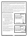
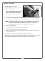
1” ELECTRIC WATER PUMP
MODEL NO: BIP1500
PART NO: 7230335
OPERATION & MAINTENANCE
INSTRUCTIONS
LS0714
INTRODUCTION
Thank you for purchasing this Clarke Water Pump.
Before attempting to use this product, please read this manual thoroughly and
follow the instructions carefully. In doing so you will ensure the safety of yourself
and that of others around you, and you can look forward to your purchase
giving you long and satisfactory service.
DESCRIPTION
This non-submersible centrifugal pump is designed to pump clean water in
gardens for spraying and irrigation purposes and for pumping water to
greenhouses. It can also be used for boosting running water feed pressure (not
drinking water) or for pumping out wells or ponds. Operating with
contaminated or salt water should be avoided.
WARNING: THIS SYMBOL IS USED THROUGHOUT THE USER GUIDE
WHENEVER THERE IS A RISK OF PERSONAL INJURY. ENSURE THAT
THESE WARNINGS ARE READ AND UNDERSTOOD AT ALL TIMES.
Your CLARKE water pump has been designed to give long and trouble free
service. If, however, having followed the instructions in this booklet carefully,
you encounter problems, take the unit to your local Clarke dealer.
Please keep these instructions in a safe place for future reference.
GUARANTEE
This product is guaranteed against faulty manufacture for a period of 12
months from the date of purchase. Please keep your receipt which will be
required as proof of purchase.
This guarantee is invalid if the product is found to have been abused or
tampered with in any way, or not used for the purpose for which it was
intended.
Faulty goods should be returned to their place of purchase, no product can
be returned to us without prior permission.
This guarantee does not effect your statutory rights.
2
Parts & Service: 020 8988 7400 / E-mail: [email protected] or [email protected]
GENERAL SAFETY PRECAUTIONS
Before using this equipment it is in your own interest to read and pay attention
to the following safety rules.
WARNING: ALWAYS CONNECT THE PUMP TO AN EARTHED POWER SUPPLY
VIA AN RCD.
1. ALWAYS keep the working area clean and well lit. Floors should always be
kept clear. Cluttered or dark areas invite accidents.
2. NEVER over-reach. Keep your proper footing and balance at all times
when installing or maintaining the pump.
3. NEVER direct any water discharge towards electrical wiring or equipment.
4. ALWAYS thoroughly familiarise yourself with this pump & its operation, and
follow all instructions in this manual. Never allow persons unfamiliar with
these instructions to instal or operate the pump.
5. ALWAYS ensure that the pump is properly installed to prevent it from
moving during operation, and that the immediate area surrounding the
pump is kept clear.
6. ALWAYS maintain the pump with care and keep it clean for best / safest
performance.
7. NEVER use this product if any part is damaged. Have it inspected and
repaired by your local Clarke dealer. Always turn the pump off before
carrying out any maintenance.
8. NEVER modify this pump in any way. Use it ONLY for the purpose for which it
is designed.
9. NEVER use for pumping flammable liquids or corrosive chemicals. This
pump is designed to pump clean water only.
11. ALWAYS have the pump serviced by your local Clarke dealer, using only
identical replacement parts. This will ensure the safety of the pump is
maintained. The use of non standard parts could be hazardous.
12. NEVER allow the pump to run dry.
CAUTION: THIS PUMP IS NOT A SUBMERSIBLE PUMP. ON NO ACCOUNT
SHOULD IT EVER BE IMMERSED IN WATER.
3
Parts & Service: 020 8988 7400 / E-mail: [email protected] or [email protected]
INSTALLATION
Because of the number of possible installations, no accessories are supplied
with your pump, however accessories are available from your nearest Clarke
dealer. See the suggested list on page 13.
NOTE: It is recommended that the end user should consult a qualified
installer if there are any doubts as to the suitability of this product
for a particular installation.
IMPORTANT: The pump MUST NOT be connected to the mains power supply
until all hose/pipe installation is completed.
INSTALLATION OF THE PUMP
The pump must always be installed and operated in a horizontal position i.e.
with the outlet port facing vertically upwards. The fixing holes in the base
should be used to secure the pump firmly in it’s operating position. Mount the
pump on raised blocks or a purpose built platform to protect it from flooding.
Some kind of anti-vibration mounting is also desirable.
Always ensure there is adequate air circulation around the motor. The pump
should be installed in a dry, well ventilated enclosure, sheltered from rain.
ELECTRICAL INSTALLATION
The pump should be located at such a distance away from any pond or pool,
as to avoid the possibility of immersion and the power supply should also be a
safe distance away. If in doubt, please contact your electrical specialist and
refer to national regulations.
Avoid situations where the pump could become drenched with water as
neither the motor or terminal box are designed to be totally waterproof.
Ensure the pump & its power cable do not create a safety hazard for people
walking past it.
ELECTRICAL CONNECTIONS
WARNING! READ THESE ELECTRICAL SAFETY INSTRUCTIONS
THOROUGHLY BEFORE CONNECTING THE PRODUCT TO THE
MAINS SUPPLY.
The BIP1500 pump is fitted with a length of 1 mm2 flexible cable and a BS1363
approved plug. If you need to replace the cable or plug for any reason,
please follow the instruction on the next page.
4
Parts & Service: 020 8988 7400 / E-mail: [email protected] or [email protected]
FITTING THE CABLE
Do not attempt electrical installation
work if you are in any doubt as to
how it should be done correctly.
Consult a qualified electrician.
The pump must be wired according
to the diagram, after removing the
cover plate, ensuring the following
principles are observed:
• The cable used must be the
correct size to ensure it is a tight
fit in the cable gland.
• Ensure the cable gland is
correctly used. The clamp must
firmly hold the outer cable
sheath and not the wires.
• Fit a crimp style ring terminal to
the earth wire and make sure
that it is correctly connected to
the earth terminal. The ring
terminal should be placed
between the two washers, and
the screw suitably tightened.
FITTING THE PLUG
WARNING! THE WIRES IN THE POWER CABLE SHOULD BE
COLOURED IN ACCORDANCE WITH THE FOLLOWING CODE:
(Blue = Neutral
Brown = Live Yellow and Green = Earth
To ensure that the colours of the wires in the power cable correspond with the
markings on the terminals of your plug, proceed as follows.
• The wire which is coloured Blue must be connected to the terminal
which is marked N or coloured Black.
• The wire which is coloured Brown must be connected to the terminal
which is marked L or coloured Red.
• The wire which is coloured Yellow and Green must be connected to
the terminal which is marked E or
or coloured Green
5
Parts & Service: 020 8988 7400 / E-mail: [email protected] or [email protected]
.
Plug must be BS1363/A approved.
Always fit a 13 Amp fuse.
Earth
(Green and Yellow)
Live
Neutral
(Brown)
(Blue)
Ensure that the outer sheath of the cable is firmly held by the clamp
• Before switching the product on, make sure that the voltage of your
electricity supply is the same as that indicated on the rating plate.
This product is designed to operate on 230VAC 50Hz. Connecting it
to any other power source may cause damage.
We strongly recommend that this machine is connected to the mains supply
via a Residual Current Device (RCD))
If in any doubt, consult a qualified electrician. DO NOT attempt any
connections yourself.
PIPE/HOSE CONNECTIONS
The pump inlet can be connected to any water source depending upon the
installation layout, and the discharge outlet should be directed as required.
The diameter of the inlet/outlet
connectors is 1” BSP (25.4 mm).
Therefore hoses with the same
diameter should be used and
secured with a suitable 1” hose
adaptor. Ensure all connections are
air tight. Tighten them enough to
secure the hose during pressurised
operation, but not so tight as to crack
any plastic inlet/outlet adaptors.
If the pump is going to be a
permanent fixture, vibration and
strain on adjacent parts can be
reduced by connecting a short flexible hose between any rigid pipework and
the pump.
6
Parts & Service: 020 8988 7400 / E-mail: [email protected] or [email protected]
The performance of your pump will be affected by the diameter of the inlet
pipe - any restriction will greatly reduce the flow. We recommend that you
always use a pipe diameter at least equal to, or greater than the diameter of
the pump connections.
To prevent unnecessary strain ensure that adequate support is provided to the
hoses and pipes. They will be considerably heavier when filled with water.
It is suggested that suction and delivery isolation valves are fitted in order to
isolate the pump. A gate valve may be installed in-line on the delivery side of
the pump which can be adjusted as required to regulate the flow of water
and can assist in priming the pump.
Protect the pump and pipework from freezing with the addition of suitable
lagging. The formation of ice may cause serious damage.
SUCTION LIFT OR GRAVITY FEED
The diagrams illustrate possible
methods of pipework installation.
It is possible to draw water from a
sunken pool or well providing the
suction lift does not exceed the
distance specified for your pump.
• The suction lift i.e. the vertical
distance between the water
level and the pump should not
exceed 7 metres.
When suction lift is used to draw
water into the pump it is essential that
all connections and hoses are
completely air tight, otherwise the
system will not work.
However, the pump may be gravity
fed, that is, drawing water from an
above ground tank.
A foot valve/filter should be fitted to
the lower end of the suction hose, (as
illustrated), to help retain water in the
suction system. Remember.... this is
NOT a self priming pump.
7
Parts & Service: 020 8988 7400 / E-mail: [email protected] or [email protected]
PRIMING THE PUMP
Before pumping, you must
completely fill the suction side with
water to prime the pump which is
carried out as follows:1. With all inlet pipes/hoses and foot
valve in position, but no outlet
hose connected, pour water into
the outlet port until all the air is
expelled.
2. Connect the outlet hose to the outlet port. If the outlet hose is already
connected, a priming hole and threaded plug are provided, adjacent to
the outlet as shown.
NOTE: As the priming hole is quite small, it is recommended to fill the inlet
pipe with water before connecting to the pump, and top up
through the priming hole once the pipe is connected.
3. Switch on the pump.
• Water should start to flow through the system.
4. Check for leaks and make good if necessary.
5. Adjust any device which may be fitted to the outlet side of the pump, to
maximise efficiency.
Do not place any restriction on the inlet side of the pump.
Remember - this pump is designed for pumping CLEAN WATER ONLY. DO NOT
USE for pumping chemicals or other flamable or corrosive liquids.
8
Parts & Service: 020 8988 7400 / E-mail: [email protected] or [email protected]
OPERATION
1. Open any valves in the pipeline.
2. If operating the pump for the first time, prime the pump as described.
NOTE: The pump is only self-priming when filled with water. Refilling is
only necessary if the pump has been drained, or if all the water
has been lost.
3. Connect to the power supply and switch on. Water should start to flow
through the system. Check for any leaks and make good as necessary.
• If the motor fails to start, or the pump does not deliver water, refer to
TROUBLESHOOTING. Never operate the pump when not primed with
water or if the inlet is blocked.
NOTE: Filling the suction pipe with water will speed up the priming
process, and it is suggested that a non-return valve be fitted to the
end of the suction pipe.
4. Stop the pump by switching off the power supply.
CARE DURING USE
1. Do not allow the pump to run dry, otherwise the seal between the pump
and motor may be damaged. If a leak occurs at this point, allowing water
to pass from the pump to the motor, take the pump to your Clarke dealer
for overhaul.
2. In the event of a blockage, where debris has entered the suction
chamber, it can be cleaned out as described under MAINTENANCE.
3. Should contaminants come into contact with the pump, flush through with
cold water as soon as possible to prevent damage to the pump. DO NOT
USE for pumping chemicals or other corrosive liquids (other than pool
purification chemicals in their correct mix ratio).
4. If the pump is being used to drain a pool or pond, ensure there is adequate
drainage and there is no risk of damage to property as a result of water
being discharged. If a flexible hose must be laid across a roadway, protect
it with wooden planking.
9
Parts & Service: 020 8988 7400 / E-mail: [email protected] or [email protected]
MAINTENANCE
The only maintenance required is a regular inspection to ensure that debris is
not blocking the passage of water through the pump.
If you suspect the pump is blocked by silt, leaf debris etc, disconnect it from
the power supply and back-flush to clear any blockage using a hose. You will
need to disconnect the outlet hose to do this.
Always keep the pump in a clean condition, checking regularly for loose bolts
or a damaged power cable etc.
The pump should not be taken apart by the user in the case of overhaul being
required, but should be taken to your nearest Clarke dealer for specialist
repair.
AFTER USE
After use, and if the pump will not be used over the winter period, or whenever
there is danger of freezing, always drain the pump body. If the pump has
been used with contaminated or salty water, it should be thoroughly flushed
with clean water following use, both inside and out. It should then be drained
and covered over, if not already installed in a clean, dry environment
sheltered from the weather.
Remember to re-prime the pump when returning to service.
• In the event that dismantling and overhaul of the pump is necessary,
contact your Clarke service department.
ENVIRONMENTAL RECYCLING POLICY
Through purchase of this product, the customer is taking on the
obligation to deal with the WEEE in accordance with the WEEE
regulations in relation to the treatment, recycling & recovery and
environmentally sound disposal of the WEEE.
In effect, this means that this product must not be disposed of with general
household waste. It must be disposed of according to the laws governing
Waste Electrical and Electronic Equipment (WEEE) at a recognised disposal
facility.
10
Parts & Service: 020 8988 7400 / E-mail: [email protected] or [email protected]
TROUBLESHOOTING
Problem
Cause
Solution
Pump does not run.
Thermal protection has
been activated.
If the motor has overheated, wait for it to cool
down before trying
again.
Faulty power connection Insert plug securely.
Pump fails to prime
No mains supply
Check fused power
supply and replace fuse
if necessary (check fuse
rating). Check circuit
breaker
Impeller seized/blocked
Disconnect pump from
power supply.
Investigate cause and
clear blockage
Air leaks through suction
hose joints (damaged
hose, broken clamp,
damaged.
Repair connections/
replace hose as
necessary.
Blocked inlet hose
Check pipeline for blockage. Check any inlet
valve fitted is fully open.
Pump runs but gives poor Congested material
output
inside pump
Clean out & backflush
pump.
Suction or delivery line
obstructed.
Remove obstruction and
ensure there are no kinks
in delivery line.
Inlet pipe leakage.
Check inlet pipe and
connector for leaks.
Tighten as required.
Air leaks through
damaged seal.
Renew seal.
Impeller damaged and
making poor seal.
Return to your Clarke
dealer for repair
Impeller / mechanical
seal is badly worn.
Return to your Clarke
dealer for repair.
11
Parts & Service: 020 8988 7400 / E-mail: [email protected] or [email protected]
High friction losses in the
suction line.
Avoid unnecessary
curves, restrictions or
valves
Pump badly sited result- Set pump as close as
ing in suction lift too high possible to the level of
the water to be pumped
Sudden loss of flow.
Blockage of inlet pipe
Undue vibration or noise. Excessive flow of water.
Check pipeline for
blockage.
Decrease flow of water.
by adjusting inlet/outlet
valves in system.
Resistance in inlet pipe
caused by obstruction.
Check pipe and clean
out as necessary
Loose rotating
component
Return to your dealer for
repairs.
Installation of pump is
unstable.
Stop pump and
re-position.
Air pocket in pump or
pipeline.
Release plug in impeller
housing to release air.
Damaged impeller
Return to your Clarke
dealer for repair.
12
Parts & Service: 020 8988 7400 / E-mail: [email protected] or [email protected]
SPECIFICATION
Water Classification
Clean
Maximum Delivery
45 l/min
Maximum Head
50 m
Maximum Suction Lift
7m
Operating Temperature
0-40oC
Ingress Protection Rating
IPx5
Supply
230V / 50Hz
Rated Power
800W
Input Current@ Maximum Head
3.56 A
Outlet Thread Size
1” BSP
Weight
8.6 kg
Length x Width x Height
298 x 140 x 196 mm
Sound Pressure Level
65 dB LpA
Sound Power Level
77 dB LwA
Guaranteed Sound Power Level
79 dB LwA
Uncertain Factor
2.58 (K)
ACCESSORIES
1” BSP Plastic Foot Valve Filter FVF10
Part No:7950680
1” dia Reinforced Suction/Delivery Hose
Part No:7955010
1” dia Layflat Delivery Hose 5M
Part No:7955112
1” dia Layflat Delivery Hose 10M
Part No:7955113
1” BSP Male Coupling
Part No:7950210
1” BSP In-line Water Filter
Part No:7175100
13
Parts & Service: 020 8988 7400 / E-mail: [email protected] or [email protected]
PARTS DIAGRAM
ID DESCRIPTION
PART NO
ID DESCRIPTION
PART NO
1
Screw
ZGBIP150001
16
ZGBIP150016
2
Pump Body
ZGBIP150002
17
Power Cable
ZGBIP150017
3
Impeller
ZGBIP150003
18
Terminal Box Screw
ZGBIP150018
4
O Ring
ZGBIP150004
19
Cable Seal
ZGBIP150019
5
Motor Front Cover
ZGBIP150005
20
Terminal Box
ZGBIP150020
6
Ball Bearing
ZGBIP150006
21
Power Switch
ZGBIP150021
7
Motor Rotor
ZGBIP150007
22
Terminal Box Cover
ZGBIP150022
8
Stator Coil
ZGBIP150008
23
Screw
ZGBIP150023
9
Stator
ZGBIP150009
24
Capacitor
ZGBIP150024
10
Motor Body
ZGBIP150010
25
Connector Wire
ZGBIP150025
11
Spring Washer
ZGBIP150011
26
Shaft Key
ZGBIP150026
Fan Cover
12
Motor End Cover
ZGBIP150012
27
Mechanical Seal
ZGBIP150027
13
Seal
ZGBIP150013
28
Plug Screw
ZGBIP150028
14
Fan
ZGBIP150014
29
Seal
ZGBIP150029
15
Tie Bolt
ZGBIP150015
14
Parts & Service: 020 8988 7400 / E-mail: [email protected] or [email protected]
DECLARATION OF CONFORMITY
15
Parts & Service: 020 8988 7400 / E-mail: [email protected] or [email protected]