1
UCR-150L Robot
with PC-E IV control
Installation
Operation
Maintenance
Troubleshooting
Instant Access
Parts and Service
(800) 458-1960
(814) 437-6861
www.conairnet.com
The Conair Group, Inc.
One Conair Drive
Pittsburgh, PA 15202
Phone: (412) 312-6000
Fax: (412)-312-6227
UGR003/0800
Record your equipment’s
model and serial number(s) and the date you
received it in the spaces
provided.
It is important to record the model and serial number(s) of
your equipment and the date you received it in the User
Guide. Our service department uses this information, along
with the manual number, to provide help for the specific
equipment you installed.
Keep this User Guide and all manuals, engineering prints and
parts lists together for documentation of your equipment.
Date:
Document Number:
UGR003/0900
Serial number(s):
Model number(s):
Power Specifications:
Amps
Volts
Phase
Cycle
DISCLAIMER: The Conair Group, Inc., shall not be liable for errors
contained in this User Guide or for incidental, consequential damages in connection with the furnishing, performance or use of this
information. Conair makes no warranty of any kind with regard to
this information, including, but not limited to the implied warranties
of merchantability and fitness for a particular purpose.
Copyright 2000
THE CONAIR GROUP, INC.
All rights reserved
INTRODUCTION . . . . . . . . . . . . . . . . . . .1-1
Purpose of the User Guide . . . . . . . . . . . . . . . . . . . . . . . . .1-2
How the Guide is Organized . . . . . . . . . . . . . . . . . . . . . . .1-2
Your Responsibility as a User . . . . . . . . . . . . . . . . . . . . . .1-2
ATTENTION: Read this so no one gets hurt . . . . . . . . . . .1-3
TABLE OF
CONTENTS
DESCRIPTION . . . . . . . . . . . . . . . . . . . .2-1
What is the UCR-150L Robot? . . . . . . . . . . . . . . . . . . . . .2-2
Typical Applications . . . . . . . . . . . . . . . . . . . . . . . . . . . . .2-2
Limitations . . . . . . . . . . . . . . . . . . . . . . . . . . . . . . . . . . . .2-3
How the UCR-150L Robot Works . . . . . . . . . . . . . . . . . . .2-3
UCR-150L Robot Features . . . . . . . . . . . . . . . . . . . . . . . .2-4
Specifications . . . . . . . . . . . . . . . . . . . . . . . . . . . . . . . . . .2-5
Optional Equipment . . . . . . . . . . . . . . . . . . . . . . . . . . . . . .2-6
INSTALLATION . . . . . . . . . . . . . . . . . . . .3-1
Unpacking the Boxes . . . . . . . . . . . . . . . . . . . . . . . . . . . . .3-2
Cautions and Warnings . . . . . . . . . . . . . . . . . . . . . . . . . . .3-3
Preparing for Installation . . . . . . . . . . . . . . . . . . . . . . . . . .3-4
Preparing the Platen . . . . . . . . . . . . . . . . . . . . . . . . . . . . . .3-5
Positioning the Robot . . . . . . . . . . . . . . . . . . . . . . . . . . . . .3-6
Connecting the Robot . . . . . . . . . . . . . . . . . . . . . . . . . . . .3-6
Setting Gripper Position . . . . . . . . . . . . . . . . . . . . . . . . . . .3-8
Setting Strip Positions . . . . . . . . . . . . . . . . . . . . . . . . . . . .3-9
Connecting Air Pressure . . . . . . . . . . . . . . . . . . . . . . . . . .3-10
Adjusting the Sprue Verification Switch . . . . . . . . . . . . . .3-10
Adjusting the Speed . . . . . . . . . . . . . . . . . . . . . . . . . . . . .3-11
Verifying the Electrical Interface . . . . . . . . . . . . . . . . . . .3-12
Manual Testing . . . . . . . . . . . . . . . . . . . . . . . . . . . . . . . .3-14
Automatic Testing . . . . . . . . . . . . . . . . . . . . . . . . . . . . . .3-15
OPERATION . . . . . . . . . . . . . . . . . . . . . .4-1
Hand Control Features . . . . . . . . . . . . . . . . . . . . . . . . . . . .4-2
Before Starting . . . . . . . . . . . . . . . . . . . . . . . . . . . . . . . . .4-2
Starting the Robot . . . . . . . . . . . . . . . . . . . . . . . . . . . . . . .4-3
Stopping the Robot . . . . . . . . . . . . . . . . . . . . . . . . . . . . . .4-3
Emergency Stopping . . . . . . . . . . . . . . . . . . . . . . . . . . . . .4-3
Viewing Information . . . . . . . . . . . . . . . . . . . . . . . . . . . . .4-4
Operating Manually . . . . . . . . . . . . . . . . . . . . . . . . . . . . . .4-5
Starting Automatic Operation . . . . . . . . . . . . . . . . . . . . . . .4-6
Choosing the Mold . . . . . . . . . . . . . . . . . . . . . . . . . . . . . .4-7
Programming the Motion Sequence . . . . . . . . . . . . . . . . . .4-8
UGR003/0900
UCR-150L Robots
i
TABLE OF
CONTENTS
CONT’D
OPERATION . . . . . . . . . . . . . . . . . . . .CONT’D
Programming Home, Grip and Vacuum Positions . . . . . . .4-10
Monitoring Input/Output . . . . . . . . . . . . . . . . . . . . . . . . .4-12
Setting Timer Values . . . . . . . . . . . . . . . . . . . . . . . . . . . .4-13
Choosing Timer Settings . . . . . . . . . . . . . . . . . . . . . . . . .4-14
Adjusting Traverse Movement . . . . . . . . . . . . . . . . . . . . .4-15
Restarting Automatic Operation . . . . . . . . . . . . . . . . . . . .4-16
Answering an Alarm . . . . . . . . . . . . . . . . . . . . . . . . . . . .4-16
MAINTENANCE . . . . . . . . . . . . . . . . . . . .5-1
Maintenance Features . . . . . . . . . . . . . . . . . . . . . . . . . . . .5-2
Warnings and Cautions . . . . . . . . . . . . . . . . . . . . . . . . . . .5-2
Preventative Maintenance Schedule . . . . . . . . . . . . . . . . . .5-4
Checking Electrical Connections . . . . . . . . . . . . . . . . . . . .5-6
TROUBLESHOOTING . . . . . . . . . . . . . . . .6-1
Before Beginning . . . . . . . . . . . . . . . . . . . . . . . . . . . . . . . .6-2
A Few Words of Caution . . . . . . . . . . . . . . . . . . . . . . . . . .6-2
Identify the Cause of a Problem . . . . . . . . . . . . . . . . . . . . .6-2
Answering an Alarm . . . . . . . . . . . . . . . . . . . . . . . . . . . . .6-3
The Robot Does Not Cycle . . . . . . . . . . . . . . . . . . . . . . . .6-4
The Mold is Not Working Properly . . . . . . . . . . . . . . . . . .6-5
The Arm is Not Working Properly . . . . . . . . . . . . . . . . . . .6-6
Strip Motion is Not Working . . . . . . . . . . . . . . . . . . . . . . .6-7
There is No Horizontal Motion . . . . . . . . . . . . . . . . . . . . .6-8
The Gripper Does Not Work . . . . . . . . . . . . . . . . . . . . . . .6-9
There is No Vacuum . . . . . . . . . . . . . . . . . . . . . . . . . . . . .6-10
APPENDIX . . . . . . . . . . . . . . . . . . . . . .A-1
Customer Service . . . . . . . . . . . . . . . . . . . . . . . . . . . . . . .A-1
Guarantee/Warranty . . . . . . . . . . . . . . . . . . . . . . . . . . . . .A-2
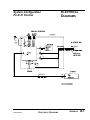
Electrical Diagrams . . . . . . . . . . . . . . . . . . . . . . . . . . . . . .B-1
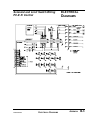
System Configuration . . . . . . . . . . . . . . . . . . . . . . . . .B-1
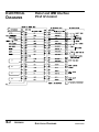
Robot and IMM Interface . . . . . . . . . . . . . . . . . . . . . .B-2
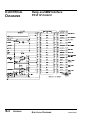
Solenoid and Limit Switch Wiring . . . . . . . . . . . . . . . .B-3
Relay and IMM Interface . . . . . . . . . . . . . . . . . . . . . . .B-4
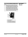
Solenoid Valves . . . . . . . . . . . . . . . . . . . . . . . . . . . . . . . . .C-1
PARTS/DIAGRAMS . . . . . . . . . . . . . . .P/D-1
ii
UCR-150L Robot
UGR003/0900
INTRODUCTION
● Purpose of the User Guide . . . .1-2
● How the User Guide
is organized . . . . . . . . . . . . . . .1-2
● Your Responsibilities
as a User . . . . . . . . . . . . . . . .1-2
● ATTENTION: Read this so
no one gets hurt . . . . . . . . . . .1-3
UGR003/0900
UCR-150L Robot
1-1
PURPOSE OF
THE USER
GUIDE
This User Guide describes the Conair UCR-150L Robot with
the PC-E IV control, and explains step-by-step how to install,
operate, maintain and repair this equipment.
HOW THE USER
GUIDE IS
ORGANIZED
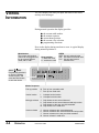
Symbols have been used to help organize the User Guide and
call your attention to important information regarding safe
installation and operation.
YOUR
RESPONSIBILITY
AS A USER
Before installing this product, please take a few moments to
read the User Guide and review the diagrams and safety information in the instruction packet. You also should review manuals covering associated equipment in your system. This
review won’t take long, and it could save you valuable installation and operating time later.
Symbols within triangles warn of conditions that could
be hazardous to users or could damage equipment.
Read and take precautions before proceeding.
1
Numbers within shaded squares indicate tasks or steps
to be performed by the user.
◆
A diamond indicates the equipment’s response to an
action performed by the user.
❒
●
An open box marks items in a checklist.
A shaded circle marks items in a list.
You must be familiar with all safety procedures concerning
installation, operation and maintenance of this equipment.
Responsible safety procedures include:
● Thorough review of this User Guide, paying particular
attention to hazard warnings, appendices and related diagrams.
● Thorough review of the equipment itself, with careful
attention to voltage sources, intended use and warning
labels.
● Thorough review of instruction manuals for associated
equipment.
● Step-by-step adherence to instructions outlined in this
User Guide.
1-2
INTRODUCTION
UCR-150L Robot
UGR003/0900
We design equipment with the user’s safety in mind. You can
avoid the potential hazards identified on this machine by following the procedures outlined below and elsewhere in the
User Guide.
ATTENTION:
READ THIS
SO NO
ONE GETS HURT
WARNING: Improper installation, operation, or servicing may result in
equipment damage or personal injury.
This equipment should only be installed, adjusted, and serviced by qualified technical personnel who are familiar with the construction, operation, and potential hazards of this type of
machine.
All wiring, disconnects, and fuses should be
installed by qualified electrical technicians in
accordance with electrical codes in your region.
Always maintain a safe ground. Do not operate
the equipment at power levels other than what
is specified on the machine serial plate.
WARNING: Voltage hazard.
This equipment is powered by alternating current, as specified on the machine serial tag and
data plate.
A properly sized conductive ground wire from
the incoming power supply must be connected
to the chassis ground terminal inside the electrical enclosure. Improper grounding can result in
severe personal injury and erratic machine
operation.
Always disconnect and lock out the incoming
main power source before opening the electrical
enclosure or performing non-standard operating
procedures such as routine maintenance. Only
qualified personnel should perform troubleshooting procedures that require access to
the electrical enclosure while power is on.
UGR003/0900
UCR-150L Robot
INTRODUCTION
1-3
DESCRIPTION
● What is the UCR-150L Robot? . .2-2
● Typical Applications . . . . . . . . . .2-2
● Limitations . . . . . . . . . . . . . . . . .2-3
● How the Robot Works . . . . . . . .2-3
● UCR-150L Robot Features . . . . .2-4
● Specifications . . . . . . . . . . . . . .2-5
● Optional Equipment . . . . . . . . . .2-6
UGR003/0900
UCR-150L Robot
2-1
WHAT IS THE
UCR-150L
ROBOT?
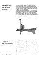
The Conair UCR-150L Robot is a pneumatic robot that
removes the sprue/part from the injection molding machine.
The UCR-150L minimizes injection machine pause time with
a fast take-out time (1.5 second) by utilizing the slide cylinder
in addition to the main arm cylinder.
The robot is mounted on a fixed platen on the injection mold
machine. When the mold-open-complete signal goes from the
mold machine to the robot controller, the strip frame slides
down at the same time the main cylinder arm enters the mold
area; the gripper grips the sprue/part and removes the item to a
designated area. When the arm moves outside the mold area
the robot can release the sprue/part with or without the optional second descent.
TYPICAL
APPLICATIONS
Conair UCR-150L Robot isideal for applications requiring
quick, consistent part removal. The robot exchanges signals
via the SPI interface on the mold machine to ensure predictable, constant cycle times. This feature avoids setup problems and allows accurate time quoting for production and
maintenance schedules.
Use the UCR-150L Robot to eliminate common problems:
● inconsistent cycle times
● improper part/sprue separation
● unsafe sprue/part removal
2-2
DESCRIPTION
UCR-150L Robot
UGR003/0900
Choose Conair UCR-150L Robot when you want a low cost,
easily maintained robot. The UCR-150L Robot has a long vertical stoke (950 mm) that allows easy adjustment to an injection mold machine. The robot does not have a swing in/swing
out movement; rather it transverses the beam. Maximum payload with standard gripper is 4.4 lb. (2 Kg), and without gripper, 6.6 lb. (3 Kg).
LIMITATIONS
The UCR-150L Robot exchanges signals via the SPI interface
on the mold machine. The hand control provides the buttons
for controlling and monitoring the robot. From the hand control you can:
HOW THE
UCR-150L
ROBOT WORKS
● monitor the input/output status
● set and adjust cycle timers in both manual and automatic
mode
● adjust mode
● operate/stop the robot manually
● operate the robot automatically
● store programs
The robot receives the signal from the mold machine to
remove the sprue/part. The robot arm moves into the mold
area, grips the part, raises out of the mold and places the part
in a specific location. The robot sends a signal to the mold
machine to begin the next cycle. Each robot is equipped with a
part verification switch to stop the molding machine if a
sprue/part is missed.
UGR003/0900
UCR-150L Robot
DESCRIPTION
2-3
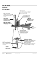
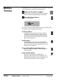
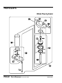
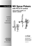
UCR-150L
ROBOT
FEATURES
Slide cylinder
Main arm cylinder
slides the strip frame up and down
at the same time as the main arm
ascends and descends.
vertically moves the gripper
to remove part from mold
machine.
Vacuum generator
provides vacuum for
optional EOAT suction
Cable Track
LM guide
protects tubing and
wires as arm moves
maintains the linear
motion of the arm
Main strip cylinder
strips part from mold
after gripping.
Base
holds robot in
position.
Traverse cylinder
moves the mobile frame as
the part/sprue is removed
from the mold machine.
Safety lock cylinder
prevents arm from dropping if pneumatic pressure suddenly drops.
EOAT mounting plate
Wrist flip cylinder
holds the optional end-ofarm tooling
positions the gripper or end-of-arm
tooling horizontally or vertically.
Gripper
picks up part/sprue in
mold machine
2-4
DESCRIPTION
UCR-150L Robot
UGR003/0900
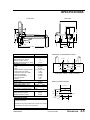
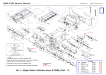
SPECIFICATIONS
Front view
11 {279}
8 {203}
64 {1626}
8 {203}
MODEL
Performance characteristics
Molding Machine Size
Minimum take out time seconds
Minimum cycle time seconds
Maximum payload with sprue grip lb {kg}
Dimensions inches {mm}
Height
Width
Depth
Distance from face of platen (min-max)
Gripper center to top of platen
Tooling plate center to top of platen
Main arm vertical stroke
Main arm horizontal stroke
Main arm strip stroke
Wrist flip
Weight lb {kg}
Shipping weight
Installed weight (without control box)
Electrical Requirements amps
110V/1 phase/ 50 or 60 Hz
240V/1 phase or 3 phase/50 or 60 Hz
Utility requirements
Air consumption ft3 {l/min}
Working air pressure psi {bar}
Maximum air pressure psi {bar}
UCR-150L
SPECIFICATION NOTES:
Maximum payload increases to 6.6 lb {3 kg} when the sprue
grip tooling is removed.
65 {1165}
35 {889}
MOUNTING TO STATIONARY PLATEN
0.8 {20}
CL
65 {1651}
88 {2235}
46 {1168}
25.5 - 6.5 {647-165}
4 {102}
11.5 {292}
37 {950}
47 {1200}
5 {125}
90°
8 {232}
80 {5.5}
100 {6.9}
6
{152}
max 25.5 {648}
up to 300 ton
1.5
8
4.4 {2}
635 {288}
485 {220}
running
peak
0.5
20
0.25
10
43 {1092}
11.5 {292}
4 {101.6}
13 {330}
23 {584}
35 {889}
Side view
6 {150}
0.59
{15.0}
2.362 {60}
4.724
{120}
9.448 {240}
2.362 {60}
11 {280}
6 bolt holes 1/2 inch - 13 tap, 1.25 deep
BASIC TOOLING PATTERN
4.3 {110}
2.7
{70}
1.575
{40}
4 x M6
1.5 {40}
2.756
{70}
Specifications may change without notice. Check with a Conair
representative for the most current information.
UGR003/0900
UCR-150L Robot
DESCRIPTION
2-5
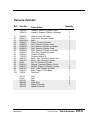
OPTIONAL
EQUIPMENT
Available options include:
● Extended strip stroke
Extends the kick stroke motion for deep draw parts (typically used with end-of-arm tooling)
● End-of-arm tooling
Used for light duty part removal.
2-6
DESCRIPTION
UCR-150L Robot
UGR003/0900
INSTALLATION
● Unpacking the Boxes . . . . . . . . .3-2
● Cautions and Warnings . . . . . . .3-3
● Preparing for Installation . . . . . .3-4
● Preparing the Platen . . . . . . . . .3-5
● Positioning the Robot . . . . . . . .3-6
● Connecting the Robot . . . . . . . .3-6
● Setting Gripper Position . . . . . .3-8
● Setting Strip Positions . . . . . . . .3-9
● Connecting Air Pressure . . . . .3-10
● Adjusting the Sprue
Verification Switch . . . . . . . .3-10
● Adjusting the Speed . . . . . . . .3-11
● Verifying the
Electrical Interface . . . . . . . .3-12
● Manual Testing . . . . . . . . . . . . .3-14
● Automatic Testing . . . . . . . . . .3-15
UGR003/0900
UCR-150L Robot
3-1
UNPACKING THE
BOXES
The UCR-150L Robot comes fully assembled in a single
crate.
CAUTION: Lifting
To avoid personal injury or damage to the robot,
lift the robot using a forklift or hoist with straps
that have been positioned at the robot's center
of gravity.
1
Carefully uncrate the robot and its
components.
2
Remove all packing material,
protective paper, tape, and plastic. Compare contents to
the shipping papers to ensure that you have all the parts.
3
Carefully inspect all components to make sure
no damage occurred during shipping. If any damage is
found, notify the shipping agent immediately. Check all
wire terminal connections, bolts, and any other electrical
connections, which may have come loose during shipping.
4
Record serial numbers and specifications
in the blanks provided on the back of the User Guide's
title page. This information will be helpful if you ever
need service or parts.
You are now ready to begin installation.
3-2
INSTALLATION
UCR-150L Robot
UGR003/0900
CAUTION: Moving the Robot
When you receive the robot, the swing arm is
bolted to prevent movement. Leave the bolt in
place until the robot is mounted on the press.
Remove after mounting.
CAUTIONS AND
WARNINGS
WARNING: Improper installation, operation, or servicing may result in
equipment damage or personal injury.
This equipment should only be installed, adjusted, and serviced by qualified technical personnel who are familiar with the construction, operation, and potential hazards of this type of
machine.
All wiring, disconnects, and fuses should be
installed by qualified electrical technicians in
accordance with electrical codes in your region.
Always maintain a safe ground. Do not operate
the equipment at power levels other than what
is specified on the machine serial tag and data
plate.
UGR003/0900
UCR-150L Robot
INSTALLATION
3-3
PREPARING FOR
INSTALLATION
Plan the location. Make sure the area where the robot is
installed has the following:
● A grounded power source. Check the robot’s serial
tag for the correct amps, voltage, phase, and cycle. All
wiring should be completed by qualified personnel and
comply with your region’s electrical codes.
● Air pressure source. The robot requires a working
pressure of 80 PSI and a maximum pressure of 100
PSI for gripping and vacuum release.
● Clearance for safe operation and maintenance.
Make sure there is enough clearance around the robot
for movement, maintenance and servicing. Be sure the
robot has proper clearance to avoid structures, utilities,
overhead cranes, material hoppers and loading pipes, as
well as other machines and equipment. Be sure that the
maximum envelope is clearly marked and protected
from entry by personnel during operation. The maximum envelope is the volume of space encompassing
the maximum designed movement of ALL robot parts,
including the end of arm tooling, work piece and
attachments.
Perform the installation in the following order:
❒
❒
❒
❒
❒
❒
❒
❒
3-4
INSTALLATION
Prepare the platen.
Move the robot into position on the platen and attach.
Connect the robot cables.
Adjust the grip and strip movement WITHOUT air
pressure (manually move the arm).
Attach air line and apply pressure.
Make adjustments to the robot (grip, speed, etc.)
Run robot in manual mode, making any adjustments
needed to prevent damage to the robot, mold machine,
and parts. Check interface to assure that mold machine
does not close on robot arm.
Run robot in automatic mode. Do this step only after
robot has been thoroughly tested in the manual mode to
prevent damage to equipment and parts.
UCR-150L Robot
UGR003/0900
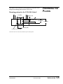
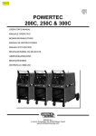
Drill holes in the stationary (fixed) platen to accept the robot
using the mounting pattern for the UCR-150L.
Mounting pattern for the UCR-150L Robot*.
11 (280)
PREPARING THE
PLATEN
0.591 (15)
2.953 (75)
5.315 (135)
5.9 (150)
9.448 (240)
6 x 1/2-13 x 1 1/4 dp
*Dimensions shown are inches (mm). Machine flat spacer mounting surface.
UGR003/0900
UCR-150L Robot
INSTALLATION
3-5
POSITIONING
THE ROBOT
CAUTION: Lifting
To avoid personal injury or damage to the robot,
lift the robot using a hoist. Place the straps
around the swing shaft between the strip frame and
the base.
1
Use a sling to lift the robot.
Place a sling under both ends of the beam and under the
traverse arm.
2
Move the robot into position.
Carefully hoist the robot into position on the platen.
3
Secure the robot to the platen with the
supplied screws, lock washers, and flat washers.
4
Remove any shipping brackets
holding the arms.
CONNECTING
THE ROBOT
WARNING: Electrical hazard
Before performing any work on this product, disconnect and lock out electrical power sources
to prevent injury from unexpected energization
or start-up.
WARNING: Improper installation, operation, or servicing may result in
equipment damage or personal injury.
This equipment should only be installed, adjusted, and serviced by qualified technical personnel who are familiar with the construction, operation, and potential hazards of this type of
machine.
All wiring, disconnects, and fuses should be
installed by qualified electrical technicians in
accordance with electrical codes in your region.
Always maintain a safe ground. Do not operate
the equipment at power levels other than what
is specified on the machine serial tag and data
plate.
3-6
INSTALLATION
UCR-150L Robot
UGR003/0900
WARNING: Crushing Injury
This device has high speed moving parts that
can cause crushing injuries. Keep body parts
and clothing away from moving parts. Always
disconnect the robot from compressed air
sources before servicing.
1
Plug the hand-held control into the control
box on the back of the robot.
2
Check to see what the power output is from
the IMM to the robot. You need to tap wires so that power
can go to the IMM SPI half 30 and 31:
For IMM Output
Voltage:
Choose:
IMPORTANT: Always refer to
the wiring diagrams that
came with your robot before
making electrical connections. The diagrams show the
minimum size main power
cable required for your robot,
and the most accurate electrical component information.
Place into:
110VAC / 1 phase
1 neutral wire and
1 hot wire
Place into Positions 30 and 31 of
SPI IMM half connector.
240VAC / 1 phase
1 ground wire
1 L wire
1 N wire
Place L and N wires into Positions
30 and 31 of SPI IMM half connector
(in any order) do not wire Ground
wire.
240VAC / 3 phase
X, Y, and Z wires or
R, S, and T wires
(depends on your IMM)
3
Choose any two wires and connect
into Positions 30 and 31 of the IMM
SPI half connector.
Connect the SPI connector cable into the
SPI connector on the robot control box and to the SPI
connector on the mold machine.
UGR003/0900
UCR-150L Robot
INSTALLATION
3-7
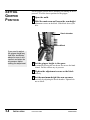
SETTING
GRIPPER
POSITION
Set the gripper position before attaching and turning on the air
pressure. To set the lowest position for the gripper:
1
2
Open the mold.
Hold the main arm and loosen the arm height
adjustment screws on the block. Slide block down cylinders.
Shock absorber
Block
If you need to adjust
the gripper height any
time after installation,
always be sure to disconnect and drain the
air pressure before
making the adjustment.
3
Set the gripper height to the sprue
by manually moving the arm down. Do not use the hand
control. Do this without any air pressure.
4
Tighten the adjustment screws on the block
securely.
5
Set the maximum height the arm can move
vertically by adjusting the shock absorber. Tighten locknut on shock.
3-8
INSTALLATION
UCR-150L Robot
UGR003/0900
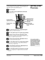
Set the strip positions before connecting the air pressure line
to prevent damage to the equipment. To set the distance the
strip stroke moves forward and backward:
1
Open the mold.
2
Loosen the Forward and Backward Stroke
adjustment levers.
Forward Stroke
adjustment plate
Forward shock
absorber
3
SETTING STRIP
POSITIONS
Backward Stroke
adjustment lever
Backward shock
absorber
Forward Strip
Stroke adjustment
levers
Move the Forward Stroke adjustment plate
by hand away from the main arm.
4
5
Move the main arm to the sprue grip position.
Push the Forward Stroke adjustment plate
toward the arm until the forward shock absorber is completely set. Tighten locknut on shock.
6
Lock the Forward Stroke adjustment levers.
This is the Strip Forward position.
7
Move the main arm to the strip back position.
Make sure the strip stroke is longer than the distance
needed for your application.
8
Lock the Backward Stroke adjustment lever.
If you need to adjust
the strip stroke any time
after installation, always
be sure to disconnect
and drain the air pressure before making the
adjustment.
This is the Strip Backward position.
9
Move the Backward shock absorber forward
until it is completely set. Tighten locknut on the shock
absorber.
UGR003/0900
UCR-150L Robot
INSTALLATION
3-9
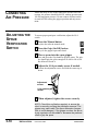
CONNECTING
AIR PRESSURE
ADJUSTING THE
SPRUE
VERIFICATION
SWITCH
Attach the shop air line to the robot at the air line hose connection. Air pressure should be 80 PSI working pressure and
100 PSI maximum pressure. Do not connect and turn on the
air until AFTER setting the gripper position and strip movement.
To ensure proper part/sprue verification, adjust the LS-4
switch.
1
Press the Manual button
to place the robot in manual mode.
2
Press the Grip (On/Off) button
to cycle the gripper open and closed.
3
Place a sprue into the open gripper
jaws and press the Grip button to grip the sprue. The gripper should grip the sprue enough to be able to lift it, but
not deform or break it.
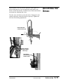
4
Adjust the LS-4 proximity sensor if needed.
Loosen the adjustment screws and slide the sensor up or
down.
Adjustment
screws
LS-4 proximity
sensor
5
When adjusted, tighten the screws securely.
NOTE: Check this verification regularly to ensure the
robot is correctly verifying the part/sprue removal. The
gripper may need reset if the sprue diameter changes
(due to mold changes). If the gripper crushes the sprue,
a grip regulator can be added to decrease the pressure
used to grip the sprue.
3-10
INSTALLATION
UCR-150L Robot
UGR003/0900
Speed control valves are used to adjust the robot speed as it
moves along the axes. You can adjust the strip stroke, arm
down (vertical movement), and the traverse motion (horizontal
movement) by adjusting the valves.
ADJUSTING THE
SPEED
Turn the valve clockwise to slow the robot. Turning the valve
counter-clockwise causes the robot to speed up. Tighten the
lock nut after making adjustments.
Horizontal flow
control valves (3)
Strip Stroke
flow control
valves (2)
Arm Down
(vertical) flow
control valve
UGR003/0900
UCR-150L Robot
INSTALLATION
3-11
VERIFYING THE
ELECTRICAL
INTERFACE
The electrical interface between the robot and the injection
molding machine is the most important part of the installation.
The interface must function correctly to maintain the safety of
the robot and the mold. As a result, the interface must be verified.
CAUTION: Equipment hazard.
The UCR-150L is designed for use with the PCE IV control.
Do not try to use a PC-E III control with this
robot. Damage will occur! Call Conair Service if
you are unsure or have any questions.
The areas that must be verified as functional and correct are
the motion controls and the inputs.
Verifying motion controls (permissives)
Electrical Diagrams are
in the Appendix.
Controling gripper movements is critical. The robot must control the following motions for safety. Check the following
movements:
● Mold Close
The robot must control the closing motion of the
mold. If the robot is not clear of the mold area, the
press must not close. Also, if the robot misses a part,
the press must be stopped from closing.
● Mold Open
The opening of the mold must be controlled by the
robot. If the arm is not in a safe area - Fully Up or
Outside the press area - the injection molding
machine should not be permitted to open.
● Mold Ejection (Forward)
The ejection of the part can be controlled by the
robot. This ensures the proper placement of the
robot gripper before the sprue/runner is ejected.
● Cycle Start (optional)
This option sends a signal from the robot to the
IMM after the mold closes to tell the IMM to begin
a new cycle.
3-12
INSTALLATION
UCR-150L Robot
UGR003/0900
Verifying the Inputs
The first four inputs must be verified. The others are optional
depending on the application.
Verify the following inputs as functional and correct:
● Mold Full Open
This signal starts the robot into the mold area. This
is a very important signal. If the robot enters, or
attempts to enter the mold at the wrong time, damage to the arm and/or mold can occur.
VERIFYING THE
ELECTRICAL
INTERFACE
CONT’D
● Mold Full Closed
This signal is sent to the robot when the mold is
fully closed or locked up.
● Press Gate Closed
This signal tells the robot that the safety gate is
closed.
Electrical Diagrams are
in the Appendix.
● Press Auto
The robot must see this signal to cycle automatically.
● E-Stop from IMM
The robot monitors the emergency stop message
from the IMM. If the robot senses the message from
the IMM, the robot stops.
● Reject Part
The IMM signals the robot there is a rejected part.
The robot grabs the part, strips it and immediately
releases it without moving it outside.
UGR003/0900
UCR-150L Robot
INSTALLATION
3-13
MANUAL
TESTING
In manual mode you can operate the robot manually using the
control buttons. To operate the robot manually:
1
Make sure the robot is stopped
and the mold is fully opened. Press the Stop button and verify the control displays Stop Mode.
2
Press the Manual button.
The LCD displays:
The robot is now in manual mode and can be operated using
the motion control buttons on the control.
Up/Down button
This button moves the main arm up and down
vertically (extends and retracts). Press once to
extend the arm; press again to retract. The gripper can grip in the down position, but does not
grip in the up position.
Swing button
Use this button to move the arm horizontally
inward and outward. The arm can traverse from
the up, forward, and backward positions, but not
from the down position.
Forward Strip/Backward Strip button
Press the button to strip forward; press again to
strip backward.
Grip (On/Off) button
Press the Grip button to manually grip a
part/sprue. Press again to release the part. The
Grip button only grips the sprue when the arm is
inside the mold and in the lowest position.
3-14
INSTALLATION
UCR-150L Robot
UGR003/0900
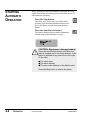
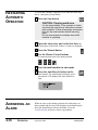
Before placing the robot into automatic operation, the Auto
signal from the press must be present for the robot to run. To
start automatic operation:
AUTOMATIC
TESTING
Press the Stop button.
The robot stops. If the arm is not in the Home
position, press the Manual button and move the
arm to the Home position, then press the Stop
button.
Press the Auto/Recycle button.
The control displays the auto mode information
and the robot begins automatic cycling.
CAUTION: Equipment damage hazard.
Press the Auto/Recycle button only when the
robot is stopped and in the home position. If the
button is pressed at any other time in the cycle
of the robot:
● The robot stops
● The alarm sounds
● The error code displays on the hand control
Press the Stop button to silence the alarm.
If the robot is not working properly at any time, turn it off
immediately and refer to the Troubleshooting section of this
User Guide.
If you do not encounter any problems during testing, proceed
to the Operation section.
UGR003/0900
UCR-150L Robot
INSTALLATION
3-15
OPERATION
● Hand Control Features . . . . . . .4-2
● Before Starting . . . . . . . . . . . . . .4-2
● Starting the Robot . . . . . . . . . . .4-3
● Stopping the Robot . . . . . . . . . .4-3
● Emergency Stopping . . . . . . . . .4-3
● Viewing Information . . . . . . . . . .4-4
● Operating Manually . . . . . . . . . .4-5
● Starting Automatic
Operation . . . . . . . . . . . . . . . .4-6
● Choosing the Mold . . . . . . . . . .4-7
● Programming the
Motion Sequence . . . . . . . . . .4-8
● Programming the Home, Grip,
and Vacuum Positions . . . . .4-10
● Monitoring Input/Output . . . . .4-12
● Setting Timer Values . . . . . . . .4-13
● Choosing Timer Settings . . . . .4-14
● Adjusting Traverse Movement .4-15
● Restarting Automatic
Operation . . . . . . . . . . . . . . . .4-16
● Answering an Alarm . . . . . . . .4-16
UGR003/0900
UCR-150L Robot
4-1
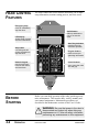
HAND CONTROL
FEATURES
The robot control has several features that allow you to input
setup information, monitor cutting process, and view errors.
Emergency Stop
press to immediately
stop the robot.
On/Off button
slide up and down to
use or not use the
robot.
LED display
shows setup, process
and error information
Auto Recycle button
puts the robot into
automatic operation
Stop button
use during normal
routine operations to
stop the robot.
Program buttons
press to enter programming information.
Numeric keypad
lets you enter numbers into the control
and save them.
BEFORE
STARTING
Control buttons
use to move the robot
arm and grip.
Before you start daily operation of the robot, perform preventative maintenance. This incudes daily, weekly, monthly and
semi-annual maintenance. Maintenance procedures are
described in the Maintenance section of this User’s Guide.
WARNING: Be sure that power to the robot is
disconnected and locked out when doing any
maintenance on it. Follow all safety rules when
performing any maintenance on this equipment.
4-2
OPERATION
UCR-150L Robot
UGR003/0900
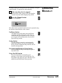
The power must be on for any robot or press operations to
occur. Slide the On/Off button on the side of the hand control.
Off Mode
STARTING THE
ROBOT
When the On/Off button on the control is in the Off position the robot is Off position, but the hand control is still
useable. The interlock signals for the mold are released.
The interlocks are still monitored, however, to ensure the
robot is in a safe position for opening and closing the
mold. NOTE: When in the Off mode, the robot does not
remove parts/sprues from the press. The operator must do
this manually.
On Mode
When the On/Off button on the control is in the On position the robot runs with the press. The operator can cycle
the robot in either manual mode or automatic mode.
To stop the robot from either Auto mode or Manual
mode, press the Stop button.
The LCD displays the message:
If, at any time, you need to immediately stop the robot,
1
Press the Emergency stop button.
The robot stops immediately. The control displays:
2
STOPPING THE
ROBOT
EMERGENCY
STOPPING
Reset the control.
After the emergency is handled, reset the control by turning the E-stop button in the direction of the arrows (clockwise).
3
Press the Stop button
to place the robot in Stop mode.
4
Continue operation by pressing the
Auto/Recycle button or the Manual button.
UGR003/0900
UCR-150L Robot
OPERATION
4-3
VIEWING
INFORMATION
The LED displays the data you input, the status of the robot,
and any error messages.
During normal operation the display provides:
●
●
●
●
●
the current mold number
the motion sequence
current home position
the current valve selection
programming directions
Error codes display during an alarm or error. A typical display
during normal operation is:
Mold Number
The current mold number;
control can be programmed
for up to seven different
molds, M01 to M07.
Home position
I - above the mold
O - outside the mold
GRIPS
GRIP Use grip solenoid valve
VAC Use vacuum solenoid valve
G+V Use grip and vacuum
solenoid valve
press
ENT.
Programming directions
to use the Up/Down
arrows to scroll, and
press the Enter button
to save the choice.
Motion Sequence
4-4
OPERATION
Pick up position
M Pick up from moveable mold
F Pick up from fixed mold
Vertical motion
L
U
L-shaped vertical motion
U-shaped vertical motion
Main grip release
2
K
3
M
Grip
Grip
Grip
Grip
Vacuum release
2
K
3
M
Vacuum
Vacuum
Vacuum
Vacuum
UCR-150L Robot
release
release
release
release
at arm second descend.
at arm second descend and strip motion.
on the way, arm third extended.
in the mold area.
release
release
release
release
at arm second descend.
at arm second extend and strip motion.
on the way, arm third extended.
in mold area.
UGR003/0900
In manual mode you can operate the robot manually using the
control buttons. To operate the robot manually:
1
Make sure the robot is stopped
OPERATING
MANUALLY
and the mold is fully opened. Press the Stop button and verify the control displays Stop Mode.
2
Press the Manual button.
The LCD displays:
The robot is now in manual mode and can be operated using
the motion control buttons on the control.
Up/Down button
This button moves the main arm up and down
vertically (extends and retracts). Press once to
extend the arm; press again to retract. The gripper can grip in the down position, but does not
grip in the up position.
Swing button
Use this button to move the arm horizontally
inward and outward. The arm can swing from
the up, forward, and backward positions, but not
from the down position.
Forward Strip/Backward Strip button
Press the button to strip forward; press again to
strip backward.
Grip (On/Off) button
Press the Grip button to manually grip a
part/sprue. Press again to release the part. The
Grip button only grips the sprue when the arm is
inside the mold and in the lowest position.
UGR003/0900
UCR-150L Robot
OPERATION
4-5
STARTING
AUTOMATIC
OPERATION
Before placing the robot into automatic operation, the Auto
signal from the press must be present for the robot to run. To
start automatic operation:
Press the Stop button.
The robot stops. If the arm is not in the Home
position, press the Manual button and move the
arm to the Home position, then press the Stop
button.
Press the Auto/Recycle button.
The control displays the auto mode information
and the robot begins automatic cycling.
CAUTION: Equipment damage hazard.
Press the Auto/Recycle button only when the
robot is stopped and in the home position. If the
button is pressed at any other time in the cycle
of the robot:
● The robot stops
● The alarm sounds
● The error code displays on the hand control
Press the Stop button to silence the alarm.
4-6
OPERATION
UCR-150L Robot
UGR003/0900
You can choose any one of seven different molds, from M01
to M07. The control must be in the Stop mode.
To choose the mold:
1
CHOOSING THE
MOLD
Press the Stop button.
The robot stops. The control must be in the
Stop mode to choose a mold.
2
Press the Program button.
The current mold number is highlighted on
the display.
3
Use the Up and Down arrows
to move sequentially through the mold numbers, M01 to M07. Each mold number displays with each press of the arrows.
4
Press the Enter button.
When the mold number you want displays,
press the Enter button to choose that mold
number.
5
Press the Stop button
to return to the Stop mode.
UGR003/0900
UCR-150L Robot
OPERATION
4-7
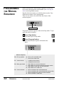
PROGRAMMING
THE MOTION
SEQUENCE
Before choosing the various motion sequences, be sure you
have chosen the appropriate mold number (see Choosing the
Mold, in the Operation section).
Decide which movements you wish the robot to make. Four
different movements can be programmed.
There are two choices for each of the four letters of the
motion sequence.
Motion sequence
Program the motion sequence when in the Stop mode. To program the motion sequence:
1
Press Stop button.
The control goes to Stop mode.
2
Press Program button.
The current motion sequence information displays.
Motion Sequence
4-8
P0 Pick up position
M Pick up from moveable mold
F Pick up from fixed mold
P1 Vertical motion
L
U
L-shaped vertical motion
U-shaped vertical motion
P2 Main grip release
2
K
3
M
Grip
Grip
Grip
Grip
P3 Vacuum release
2
K
3
M
Vacuum
Vacuum
Vacuum
Vacuum
OPERATION
UCR-150L Robot
release
release
release
release
at arm second descend.
at arm second descend and strip motion.
on the way, arm third extended.
in the mold area.
release
release
release
release
at arm second descend.
at arm second extend and strip motion.
on the way, arm third extended.
in mold area.
UGR003/0900
3
4
to move sequentially through the mold sequence
positions. Each mold sequence position underlines each time the Up or Down arrow is
pressed.
PROGRAMMING
THE MOTION
SEQUENCE
Use the Forward arrow
CONT’D
Use the Up and Down arrows
to toggle between the choices for that motion
sequence position. Each time the arrow is
pressed, the cursor moves to the next letter/number and underlines it.
5
Continue to move through the motion
sequence positions using the Up/Down arrows
and the Forward arrow until you make all your
choices.
6
Press the Enter button.
After making all of your choices for the motion
sequence, press the Enter button to program your
choice.
7
Press the Stop button.
To continue, press the Stop button.
Basic Motion Sequence
10
HOME
6
1
5
7
9
2
3
HOME
1
2
3
4
5
6
7
8
9
10
●
4
8
Home position (start, standby position)
Strip frame slide down and main arm descends (mold open)
Strip forward
Grip
Strip backward.
Main arm ascends and strip frame slides up.
Arm traverses outward and wrist flip moves to horizontal position.
Strip frame slides down and main arm descends.
Grip releases part.
Arm ascends and strip frame slides up.
Arm traverses inward and wrist flip moves to vertical position.
Arm returns to Home position.
UGR003/0900
UCR-150L Robot
OPERATION
4-9
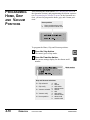
PROGRAMMING
HOME, GRIP
AND VACUUM
POSITIONS
After choosing the mold number (see Choosing the Mold, in
the Operation section), and programming the motion sequence
(see Programming the Motion Sequence in the Operation section), you need to program the home, grip, and vacuum positions.
Home position
I
O
Home position above mold
Home position outside mold
To program the Home, Grip and Vacuum positions:
1
Press the Stop button.
The control goes to Stop mode.
2
Press the Function button.
The current settings display for the chosen mold
number.
Mold number
Grip and Vacuum selections
f0: Grip solenoid
f1: Grip verify
f2: Vacuum solenoid
f3: Vacuum verify
f4: Home position
4-10
OPERATION
UCR-150L Robot
a
b
a
b
a
b
a
b
a
b
with
without
with switch
without switch
without
with
with switch
without switch
above mold
outside mold
UGR003/0900
3
Choose the function and settings you want
for the mold number listed on the display.
4
Use the Up and Down arrows
to scroll through the functions, f0 through f4. The
current function is highlighted.
5
Use the right arrow to choose the setting
(a, b). The current function choice is highlighted.
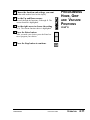
6
PROGRAMMING
HOME, GRIP
AND VACUUM
POSITIONS
CONT’D
Press the Enter button.
After you make your choices press the Enter button to program your choices.
7
Press the Stop button to continue.
UGR003/0900
UCR-150L Robot
OPERATION
4-11
MONITORING
INPUT/OUTPUT
You can monitor the status of all input and output signals
between the robot and the injection molding machine. The
input/output display can be viewed when the robot is in
Automatic mode or Manual mode.
To view input/output, press the Monitor Input/ Output
button (Mon I/O). The LCD displays input information (LS) and output information (SOL) and X shows
which switches/valves are OFF and O shows which ones are
ON.
Inputs
LS1
LS2
LS3
LS4
LSP
LSD
LSA
LSR
LSG
LSC
LSO
LSU
LSH
Move outward end proximity switch
Move inward end proximity switch
Main arm retract end (arm up) and Slide
cylinder retract end proximity switch
Part (grip) verification switch
Vacuum switch
Main arm descent end proximity switch (option)
Press in Auto signal
Rejected part signal (option)
Gate guard signal
Mold fully closed signal
Mold fully open signal
Robot ON/OFF signal
Robot home position signal
Outputs
SOL1
SOL2
SOL3
SOL4
SOL5
SOL6
SOLB
SOLS
SOLE
SOLT
Move outward solenoid valve
Move inward solenoid valve
Main arm extend/retract and Slide cylinder retract
solenoid valve
Strip forward-backward solenoid valve
Main arm grip solenoid valve
Vacuum solenoid valve
Option solenoid valve
Mold area free; permit clamp motion output
Permit ejector forward output
Emergency stop from robot output
Press the Mon I/O button again to return to the previous control display.
4-12
OPERATION
UCR-150L Robot
UGR003/0900
The robot allows you to set time delays for:
●
●
●
●
●
●
SETTING TIMER
VALUES
arm movements
part ejection
grip
cycle monitor
options
alarms
Up to 15 different timers can be set and changed while the
robot is in operation, or when the robot is stopped. Timers can
be fine tuned while the robot is running in Automatic.
To view and set the timer settings:
1
Press the Time button.
The current timer settings display, one at a time,
on the display.
2
Press the Up and Down buttons to
scroll through the timer settings. The timer setting displays as:
M01
the mold number
Timer Setting
tells which mode the
control is displaying
TIM 00
the timer setting number
3
1ST DOWN DLY.
short description of
timer setting
00.50
is the set time, in seconds,
to the second decimal place
Press the Forward button
The cursor displays under the first number to
move the cursor to the next digit on the screen.
4
Enter the new timer value.
5
Press the Enter button.
Press the number for the timer value you want to
set. The cursor moves to the next digit automatically.
For the table of timer
settings, see Choosing
Timer Settings, in the
Operation section.
The control accepts the entries and returns to the
previous display screen.
UGR003/0900
UCR-150L Robot
OPERATION
4-13
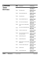
CHOOSING
TIMER
SETTINGS
4-14
OPERATION
Timer
Setting
Description
LCD Displays
TIM00
First down delay
TIMERS SETTING
1ST DOWN DLY.
TIM00 ##.##
TIM 01
Eject delay timer
TIMERS SETTING
EJECTOR DLY.
TIM01 ##.##
TIM 02
Strip forward delay timer
TIMERS SETTING
STRIP F/W DLY.
TIM02 ##.##
TIM 03
Grip delay timer
TIMERS SETTING
V+G ON DLY.
TIM03 ##.##
TIM 04
Strip backward delay timer
TIMERS SETTING
STRIP B/W DLY.
TIM04 ##.##
TIM 05
Arm first retract delay timer
TIMERS SETTING
1 ST UP DLY.
TIM05 ##.##
TIM 06
Grip or vacuum release delay
timer
TIMERS SETTING
V/G 1 OFF DLY.
TIM06 ##.##
TIM 07
Arm second retract delay timer TIMERS SETTING
2ND UP DLY.
TIM07 ##.##
TIM 08
Cycle time monitor timer
TIMERS SETTING
CYCLE TIM DLY.
TIM08 ##.##
TIM 09
Strip forward delay timer after
arm retract motion
TIMERS SETTING
STRIP O/W DLY.
TIM09 ##.##
TIM 10
Optional delay timer
TIMERS SETTING
OPTION DLY.
TIM10 ##.##
TIM 11
Optional delay timer
TIMERS SETTING
OPTION DLY.
TIM11 ##.##
TIM 12
Grip or vacuum second release TIMERS SETTING
V/G 2 OFF DLY.
delay timer
TIM12 ##.##
TIM 13
Third arm retract delay timer
TIMERS SETTING
3RD UP DLY.
TIM13 ##.##
TIM 14
Optional timer
TIMERS SETTING
OPTION DLY.
TIM14 ##.##
TIM 15
Alarm Off delay timer
TIMERS SETTING
ALARM OFF DLY.
TIM15 ##.##
UCR-150L Robot
UGR003/0900
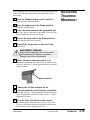
When changing to a new mold, the traverse (horizontal) movement of the arm may need adjusted. To adjust the traverse
movement:
1
Press the Manual button on the control to
place the robot in manual mode.
2
ADJUSTING
TRAVERSE
MOVEMENT
Move the main arm to the Home position
using the control buttons.
3
Lower the main arm into the open mold and
see if the grip is centered over the mold. If it is not, you
need to adjust the traverse movement.
4
Retract the main arm to the Home position.
This locks the main arm vertically.
5
Turn off the air pressure to the robot and
drain the air.
EQUIPMENT DAMAGE
Always turn off and drain air from the robot
before adjusting the traverse movement.
Damage can occur to equipment!
6
Adjust the shock absorber until it is set
completely against the arm and the arm is centered vertically over the sprue. Lock the shock absorber by tightening the locknut.
Shock absorber
7
8
Connect the air line and turn air on.
Using the manual control buttons, extend the
main arm and grip. Check alignment with the mold and
sprue. If alignment is incorrect, repeat steps 4 - 7 until
alignment is correct.
9
Press the Mon I/O button on the control.
The Home input (LSH) should be ON (O). If it is OFF
(X) move the Home actuator on the back of the traverse
beam until the Home input registers ON.
UGR003/0900
UCR-150L Robot
OPERATION
4-15
RESTARTING
AUTOMATIC
OPERATION
To restart the automatic operation cycle when the robot stops
due to a part/sprue pickup failure:
1
Press the Stop button.
CAUTION: Clearing mold area.
It is the responsibility of the operator to check
and clear the mold area is clear after a missed
parts condition. Follow all warnings and precautions for the mold machine before removing
parts.
Do not enter maximum envelope area while
machine is operating.
2
Open the safety door and verify that there is
no part/sprue in the mold. If there is, remove it manually.
3
4
Press the Manual button.
Use the Motion Control buttons
to return the main arm to the home position.
5
6
Start the mold machine in Auto mode.
Press the Auto/Recycle button on the
hand control. The robot begins automatic operation and the LCD displays the Auto Mode message:
ANSWERING
ALARM
4-16
AN
OPERATION
When an error occurs during operation, the robot stops, an
alarm sounds and the error code displays on the hand control.
Press the Stop button to silence the alarm. Go to the
Troubleshooting section to correct any problems.
UCR-150L Robot
UGR003/0900
MAINTENANCE
● Maintenance Features . . . . . . . .5-2
● Warnings and Cautions . . . . . . .5-2
● Preventative Maintenance
Schedule . . . . . . . . . . . . . . . . .5-4
● Checking Electrical
Connections . . . . . . . . . . . . . .5-6
UGR003/0900
UCR-150L Robot
5-1
MAINTENANCE
FEATURES
The UCR-150L Robot models need regular, scheduled maintenance for peak performance. Among the features that require
maintenance are:
❐ Mechanical parts
❐ Electrical parts
WARNINGS
CAUTIONS
AND
To maintain the best performance of the robot, it must be
inspected regularly. Maintenance includes a daily, weekly,
quarterly, and semi-annual (every 6 months) schedule.
Use this maintenance schedule as a guide. You may need to
shorten the time of the maintenance schedule, depending on
how often you use the robot.
Follow all precautions and warnings when working on the
equipment.
WARNING: Improper installation,
operation, or servicing may result in
equipment damage or personal injury.
This equipment should only be installed, adjusted, and serviced by qualified technical personnel who are familiar with the construction, operation, and potential hazards of this type of
machine.
Be sure the robot has proper clearance to avoid
structures, utilities, overhead cranes, material
hoppers and loading pipes, as well as other
machines and equipment.
Be sure that the maximum envelope is clearly
marked and protected from entry by personnel
during operation. The maximum envelope is the
volume of space encompassing the maximum
designed movement of ALL robot parts, including the end of arm tooling, work piece and
attachments.
5-2
MAINTENANCE
UCR-150L Robot
UGR003/0900
WARNING: Voltage Hazard
This equipment is powered by alternating current, as specified on the machine serial tag and
data plate.
Device must be properly grounded. Improper
grounding can result in severe personal injury
and erratic machine operation.
Always disconnect and lock out the incoming
main power source to the robot before performing non-standard operating procedures such as
routine maintenance. Only qualified personnel
should perform troubleshooting procedures that
require access to the electrical enclosure while
power is on.
All wiring, disconnects, and fuses should be
installed by qualified electrical technicians in
accordance with electrical codes in your region.
Always maintain a safe ground. Do not operate
the equipment at power levels other than what
is specified on the machine serial plate.
WARNING: High speed moving parts.
Do not enter maximum envelope area while
machine is operating. The maximum envelope
is the volume of space encompassing the maximum designed movement of ALL robot parts,
including the end of arm tooling, work piece and
attachments.
Do not operate machine unless interlocks/safety
devices are in place and function properly.
Robot may drop load. Do not walk under robot/
load. Failure to follow instructions could result in
injury.
UGR003/0900
UCR-150L Robot
MAINTENANCE
5-3
PREVENTATIVE
MAINTENANCE
SCHEDULE
To maintain the best performance, follow this maintenance
schedule.
● Daily
❒ Inspecting filter regulator unit
Check the bowl for water and contamination and for
correct pressure.
❒ Checking hoses and cables
Check for kinks, cuts, and tears. Replace as needed.
❒ Inspecting shock absorbers and cushions
Make sure they are operating smoothly.
❒ Checking gripper return spring
Check that the gripper return spring is operating properly.
❒ Checking residue buildup
Inspect the shafts and gripper for buildup of plastic
residue. Clean as necessary.
❒ Checking interlock functions
Make sure the interlock functions are working properly.
❒ Checking part verification
Check that the parts verification is working properly.
● Weekly, or as often as needed.
❒ Inspecting fittings and mounting hardware
Check all fittings, screws, and component mounting
hardware for tightness. Tighten as needed.
❒ Checking gripper mounting screw
Check the gripper mounting screw for tightness.
Tighten as needed.
❒ Inspecting grease fittings
Check grease fittings and grease with lithium soap
grease No. 1 or 2, as needed.
❒ Checking the safety latch cylinder
Make sure the safety latch cylinder is working properly.
❒ Testing the Emergency Stop button
Verify that the emergency stop works properly.
5-4
MAINTENANCE
UCR-150L Robot
UGR003/0900
❒ Checking angle of rotation
Check for correct angle of rotation of the arm. Adjust
as necessary.
❒ Checking timer settings
Check that settings have not changed. Adjust as needed.
PREVENTATIVE
MAINTENANCE
SCHEDULE
❒ Verifying sequence
Check that robot is performing the correct sequences.
Correct as needed.
● Monthly
❒ Inspecting the filter regulator
Check that the filter regulator is set at the correct pressure. Check the filter and clean or replace it as needed.
❒ Checking the solenoid valves
Check that the solenoid valves are working properly.
Replace as needed.
❒ Inspecting the gripper for wear
Check the gripper fingers for wear. Replace as needed.
❒ Checking the exhaust filter
Check the filter and clean or replace it as needed.
❒ Examining the suction cups
Inspect the suction cups and replace if worn or damaged.
❒ Inspecting electrical terminals
Check all electrical terminals for tightness; adjust as
needed. See Checking Electrical Connections, in the
Maintenance section.
❒ Checking all electrical cables
Inspect all electrical cables for cuts and abrasions.
Replace as needed.
❒ Inspecting hand pendant display
Check to make sure no LCD display is functioning
correctly. Replace as needed.
UGR003/0900
UCR-150L Robot
MAINTENANCE
5-5
CHECKING
ELECTRICAL
CONNECTIONS
WARNING: Electrical hazard
Before performing any work on this product,
disconnect and lock out electrical power
sources to prevent injury from unexpected energization or start-up.
WARNING: Improper installation, operation, or servicing may result in
equipment damage or personal injury.
This equipment should only be installed, adjusted, and serviced by qualified technical personnel who are familiar with the construction, operation, and potential hazards of this type of
machine.
All wiring, disconnects, and fuses should be
installed by qualified electrical technicians in
accordance with electrical codes in your region.
Always maintain a safe ground. Do not operate
the equipment at power levels other than what
is specified on the machine serial tag and data
plate.
Electrical Diagrams are
in the Appendix.
1
Be sure the main power is disconnected
and the robot is locked out. Always disconnect and lock
out the main power source before opening the unit or servicing.
2
3
Open the electrical enclosure.
Inspect all wires and connections.
Look for loose wires, burned contacts, and signs of overheated wires. Have a qualified electrician make any necessary repairs or replacements.
4
5
Close the electrical enclosure door.
Inspect the exterior power cords.
Cords should not be crimped, exposed, or rubbing against
the frame. If the interface cable or hand pendant cable
runs along the floor, make sure it is not positioned where
it could rest in pooling water or could be run over and cut
by wheels or casters.
5-6
MAINTENANCE
UCR-150L Robot
UGR003/0900
TROUBLESHOOTING
● Before Beginning . . . . . . . . . . . .6-2
● A Few Words of Caution . . . . . .6-2
● Identifying the
Cause of a Problem . . . . . . . . .6-2
● Answering an Alarm . . . . . . . . .6-3
● The Robot Does Not Cycle . . . .6-4
● The Mold is Not
Working Properly . . . . . . . . . . .6-5
● The Arm is Not
Working Properly . . . . . . . . . . .6-6
● The Strip Motion is Not
Working . . . . . . . . . . . . . . . . .6-7
● There is No Horizontal
Motion . . . . . . . . . . . . . . . . . . .6-8
● The Gripper Does Not Work . . . .6-9
● There is No Vacuum . . . . . . . . .6-10
UGR003/0900
UCR-150L Robot
6-1
BEFORE
BEGINNING
You can avoid most problems by following the recommended
installation, operation and maintenance procedures outlined in
this User Guide. If you have a problem, this section will help
you determine the cause and tell you how to fix it.
Find any wiring, parts, and assembly diagrams that were
shipped with your equipment. These are the best reference for
correcting a problem. The diagrams will note any custom features or options not covered in this User Guide.
Verify that you have all instructional materials related to the
robot. Additional details about troubleshooting and repairing
specific components are found in these materials.
Check that you have manuals for other equipment connected
in the system. Troubleshooting may require investigating other
equipment attached to, or connected with the robot.
A FEW WORDS
OF CAUTION
WARNING: Improper installation, operation, or servicing may result in
equipment damage or personal injury.
This equipment should only be installed, adjusted, and serviced by qualified technical personnel who are familiar with the construction, operation, and potential hazards of this type of
machine.
All wiring, disconnects, and fuses should be
installed and adjusted by qualified electrical
technicians in accordance with electrical codes
in your region. Always maintain a safe ground.
Do not operate the equipment at power levels
other than what is specified on the machine
serial tag and data plate.
WARNING: Electrical hazard
Before performing maintenance or repairs on
this product, disconnect and lock out electrical
power sources to prevent injury from unexpected energization or start-up.
IDENTIFYING THE
CAUSE OF A
PROBLEM
6-2
TROUBLESHOOTING
The Troubleshooting section covers problems directly related
to the operation and maintenance of the robot. This section
does not provide solutions to problems that originate with
other equipment. Additional troubleshooting help can be
found in manuals supplied with the other equipment.
UCR-150L Robot
UGR003/0900
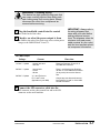
When an error occurs during operation, the robot stops, an
alarm sounds and the error code displays on the hand control.
Press the Stop button to silence the alarm. Check this table for
a description of the error:
Error Display
Area of problem
LS1 SWITCH ERROR
OR NOT ACTUATED
CHECK LS1 SWITCH
LS-1 swing-out proximity switch error or
the switch was not actuated.
LS2 SWITCH ERROR
OR NOT ACTUATED
CHECK LS2 SWITCH
LS-2 swing-in proximity switch error or the
switch was not actuated.
LS3 SWITCH ERROR
OR NOT ACTUATED
CHECK LS3 SWITCH
LS-3 arm-up proximity switch error or the
switch was not actuated.
LS4 SWITCH ERROR
OR NO PARTS VERIF.
CHECK LS4 SWITCH
LS-4 part (grip) verification switch error or
the switch was not actuated.
TIMER#08 ERROR
CYCLE TIM EXCEEDED
CHECK TIM 08
The Timer 08 cycle time is over.
LSO SWITCH ERROR
OR INTERUP. SIGNAL
CHECK LSO SWITCH
LS-0 mold fully open switch error.
LSD SWITCH ERROR
OR NOT ACTUATED
CHECK LSD SWITCH
LS-D arm descend end proximity switch
error or the switch was not actuated.
LSG SWITCH ERROR
OR NOT ACTUATED
CHECK LSG SWITCH
LS-G safety gate signal error.
LSP SWITCH ERROR
OR NOT ACTUATED
CHECK LSP SWITCH
LS-P vacuum verification switch error or
the switch was not actuated.
LSH SWITCH ERROR
OR NOT IN HOME
CHECK LSH SWITCH
LS-H robot home position switch error or
robot not at home position.
UGR003/0900
UCR-150L Robot
ANSWERING
ALARM
TROUBLESHOOTING
AN
6-3
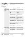
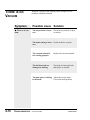
THE ROBOT
DOES NOT
CYCLE
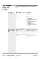
There are several reasons the robot does not cycle. You need
to check electrical connections, fuses, and the automatic setting.
Symptom
Possible cause
Solution
◆ The robot does
Electrical connections
are not correct.
Check that:
not cycle.
❒ The robot is plugged into a
❒
❒
❒
❒
◆ Automatic operation is not available.
6-4
TROUBLESHOOTING
power source.
The main power source is
on.
The interface cables are
connected.
The fuses are good.
The power to the press is
on.
The press is not set for
auto.
Check that the interface wiring
is properly connected.
The robot is not in Home
position.
Return the robot to Home
using the Manual button on the
hand control.
UCR-150L Robot
UGR003/0900
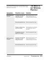
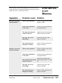
The common problems you will see with the mold are that it
will not close or it will not open. You need to check settings
and electrical connections.
THE MOLD IS
NOT WORKING
PROPERLY
Symptom
Possible cause
Solution
◆ The mold does
The arm is not in the full
up position, or at the
swing outward end.
Check the Arm Up (LS-3) and
Swing Outward End (LS-1)
switches and adjust as needed.
not close.
The safety interlock is on. Check the output and wiring.
◆ The mold does
not open.
The part verification signal is not working.
Check that the part verification
is on. Replace the switch if
necessary.
The optional cycle start
signal is not working.
Check the output and wiring.
The arm is not in the full
up position, or at the
swing outward end.
Check the Arm Up (LS-3) and
Swing Outward End (LS-1)
switches and adjust as needed.
The safety interlock is on. Check the output and wiring.
UGR003/0900
UCR-150L Robot
TROUBLESHOOTING
6-5
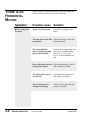
THE ARM IS
NOT WORKING
PROPERLY
Symptom
Possible cause
Solution
◆There is no arm
extension (no arm
down).
There is no air pressure.
Check air supply to the robot.
Check for leaks.
The mold is not fully
open.
Check that the interface wiring
is correct.
The robot is not swung
fully in or fully out.
Check the LS-1 and LS-2
switches and adjust as necessary.
Vertical stroke adjustment block is set too low.
Loosen stroke adjustment
block and set higher to correct
stroke.
The arm down flow control is shut off.
Adjust the down speed control;
replace as needed.
The main arm solenoid
valve is not functioning.
Replace the main arm solenoid
valve.
The air lines/seals are
damaged or leaking.
Check air lines and seals;
replace as needed.
There is no air pressure.
Check air supply to the robot.
The up solenoid is not
functioning.
Replace the up solenoid valve.
◆ There is no arm
retraction (no arm
up).
6-6
The problems you will see with the arm is that it will not
extend or retract properly. Check electrical wiring, switches,
valves, and air lines.
TROUBLESHOOTING
UCR-150L Robot
UGR003/0900
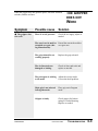
When the strip is not working properly, it does not move forward or backward. You need to adjust the strip speed control,
replace the valve, or check the air lines.
STRIP MOTION
IS NOT
WORKING
Symptom
Possible cause Solution
◆ There is no strip
forward motion.
There is no air pressure.
Check air supply to the robot.
Check for leaks.
Strip stroke adjustment
set too short.
Check strip stroke adjustment
for proper distance.
The strip forward speed
control is shut off.
Adjust the strip forward speed
control; replace as needed.
The strip valve is not
functioning.
Check the strip valve and
replace as needed.
The air lines/seals are
damaged or leaking.
Check air lines and seals and
replace as needed.
There is no air pressure.
Check air supply to the robot.
Check for leaks.
Strip stroke adjustment
set too short.
Check strip stroke adjustment
for proper distance.
◆ There is not strip
backward motion.
Adjust the strip backward
The strip backward speed speed control; replace as needcontrol is shut off.
ed.
UGR003/0900
The strip valve is not
functioning.
Check the strip valve and
replace as needed.
The air lines/seals are
damaged or leaking.
Check air lines and seals and
replace as needed.
UCR-150L Robot
TROUBLESHOOTING
6-7
THERE IS NO
HORIZONTAL
MOTION
Causes for the no horizontal motion are due to switches and
air lines. Check switches and check for air leaks.
Symptom
Possible cause
Solution
◆ The swing does
There is no air pressure.
Check the air supply to the
robot.
The arm is not in the full
up position.
Check the arm up switch and
adjust as needed.
The swing inhibitor
devices used during shipping is still attached.
Remove the swing bracket and
the screws used during shipping. See Positioning the
Robot, in the Installation section.
not move.
Part verification is not on Check and adjust the verification switches as needed.
(during Auto mode).
6-8
TROUBLESHOOTING
The swing flow controls
are shut off.
Adjust the swing speed control; replace as needed.
The air lines/seals are
damaged or leaking.
Check air lines and seals and
replace as needed.
UCR-150L Robot
UGR003/0900
When the gripper does not grab the sprue, check the solenoid,
switches, and the air lines.
THE GRIPPER
DOES NOT
WORK
Symptom
Possible cause
Solution
◆ The gripper does
There is no air pressure.
Check the air supply; adjust as
needed.
not work.
The arm is not in mold or Extend the arm in the mold or
extended over gate (durover gate area.
ing Manual mode).
UGR003/0900
The grip solenoid is not
working properly.
Replace the grip solenoid.
The air lines/seals are
damaged or leaking.
Check air lines and seals and
replace as needed.
The part/sprue is sticking
to the mold.
Adjust the ejector stroke.
Correct the mold problem.
Main grip is not selected
in Program mode.
Place grip on in Program
mode.
Gripper is faulty.
Check gripper for broken
spring or cracked housing.
Replace as needed.
UCR-150L Robot
TROUBLESHOOTING
6-9
THERE IS
VACUUM
NO
When the vacuum is not working, check settings, air line
problems, and bad solenoids.
Symptom
Possible cause Solution
◆ There is no vac-
The air pressure is incor- Check the air pressure. Adjust
rect.
as needed.
uum.
The mode setting is incor- Set the mode for vacuum.
rect.
The vacuum solenoid is
not working properly.
Replace the vacuum solenoid.
The air lines/seals are
damaged or leaking.
Check the air lines and seals
and replace as needed.
The part/sprue is sticking Adjust the ejector stroke.
to the mold.
Correct the mold problem.
6-10
TROUBLESHOOTING
UCR-150L Robot
UGR003/0900
Conair has made the largest investment in customer support in
the plastics industry. Our service experts are available to help
with any problem you might have installing and operating
your equipment. Your Conair sales representative also can help
analyze the nature of your problem, assuring that it did not
result from misapplication or improper use.
To contact Customer Service personnel, call:
From outside the United States, call: 814-437-6861
WE’RE HERE
TO HELP
HOW TO
CONTACT
CUSTOMER
SERVICE
You can commission Conair service personnel to provide onsite service by contacting the Customer Service Department.
Standard rates include an on-site hourly rate, with a one-day
minimum plus expenses.
If you do have a problem, please complete the
following checklist before calling Conair:
❒ Make sure you have all model, serial and parts list numbers
for your particular equipment. Service personnel will need
this information to assist you.
BEFORE YOU
CALL ...
❒ Make sure power is supplied to the equipment.
❒ Make sure that all connectors and wires within and between
the robot and related components have been installed correctly.
❒ Check the troubleshooting guide of this manual for a solution.
❒ Thoroughly examine the instruction manual(s) for associated equipment, especially controls. Each manual may have
its own troubleshooting guide to help you.
❒ Check that the equipment has been operated as described in
this manual.
❒ Check accompanying schematic drawings for information
on special considerations.
UGR003/0900
CUSTOMER SERVICE
Additional manuals and
prints for your Conair
equipment may be
ordered through the
Customer Service or
Parts Departments for
a nominal fee.
APPENDIX A-1
EQUIPMENT
GUARANTEE
Conair guarantees the machinery and equipment on this
order, for a period as defined in the quotation from date of
shipment, against defects in material and workmanship
under the normal use and service for which it was recommended (except for parts that are typically replaced after
normal usage, such as filters, liner plates, etc.). Conair’s
guarantee is limited to repairing or replacing, at our
option, the part or parts determined by us to be defective
after examination. The customer assumes the cost of transportation of the part or parts to and from the factory.
PERFORMANCE
WARRANTY
Conair warrants that this equipment will perform at or
above the ratings stated in specific quotations covering the
equipment or as detailed in engineering specifications,
provided the equipment is applied, installed, operated and
maintained in the recommended manner as outlined in our
quotation or specifications.
Should performance not meet warranted levels, Conair at
its discretion will exercise one of the following options:
● Inspect the equipment and perform alterations or
adjustments to satisfy performance claims. (Charges
for such inspections and corrections will be waived
unless failure to meet warranty is due to misapplication, improper installation, poor maintenance practices
or improper operation.)
● Replace the original equipment with other Conair
equipment that will meet original performance claims
at no extra cost to the customer.
● Refund the invoiced cost to the customer. Credit is
subject to prior notice by the customer at which time a
Return Goods Authorization Number (RGA) will be
issued by Conair’s Service Department. Returned
equipment must be well crated and in proper operating
condition, including all parts. Returns must be prepaid.
Purchaser must notify Conair in writing of any claim and
provide a customer receipt and other evidence that a claim
is being made.
WARRANTY
LIMITATIONS
A-2
APPENDIX
Except for the Equipment Guarantee and Performance
Warranty stated above, Conair disclaims all other warranties with respect to the equipment, express or
implied, arising by operation of law, course of dealing,
usage of trade or otherwise, including but not limited to
the implied warranties of merchantability and fitness for
a particular purpose.
GUARANTEE/WARRANTY
UGR003/0900
System Configuration
PC-E IV Control
UGR003/0900
ELECTRICAL DIAGRAMS
ELECTRICAL
DIAGRAMS
APPENDIX
B-1
ELECTRICAL
DIAGRAMS
Robot and IMM Interface
PC-E IV Control
B-2
ELECTRICAL DIAGRAMS
APPENDIX
UGR003/0900
Solenoid and Limit Switch Wiring
PC-E IV Control
UGR003/0900
ELECTRICAL DIAGRAMS
ELECTRICAL
DIAGRAMS
APPENDIX
B-3
ELECTRICAL
DIAGRAMS
Relay and IMM Interface
PC-E IV Control
B-4
ELECTRICAL DIAGRAMS
APPENDIX
UGR003/0900
CAUTION: Equipment damage hazard
Only manually set and operate these solenoid
valves when the mold is fully open. This solenoid valves will operate and the pneumatic circuit changes irrespective of the conditions of the
other solenoid valves and the mold machine.
Manually operation the solenoid valves make
the safety interlock if effective. Damabe to the
robot and mold can occur and injury to the operator can occur if the mold is not fully open when
setting and operating the solenoid valves.
SOLENOID
VALVES
A
B
C
D
E
F
A
B
C
D
E
F
UGR003/0900
Slide cylinder, up/down
Vacuum (optional)
Main arm grip
Strip Cylinder (forward/backward)
Main arm cylinder (ascend/descend)
Traverse cylinder (outward/inward)
Solenoid Vavles
APPENDIX
C-1
PARTS/DIAGRAMS
● Base . . . . . . . . . . . . . . . . . . . .P/D-2
● Traverse Cylinder . . . . . . . . . .P/D-4
● Valve . . . . . . . . . . . . . . . . . . . .P/D-6
● Valve Parts . . . . . . . . . . . . . . .P/D-8
● Slide Base . . . . . . . . . . . . . .P/D-10
● Strip Cylinder . . . . . . . . . . . .P/D-12
● Main Arm . . . . . . . . . . . . . . .P/D-14
● Main Arm Slide Unit . . . . . . .P/D-16
● Main Cylinder . . . . . . . . . . . .P/D-18
● Wrist Flip . . . . . . . . . . . . . . .P/D-20
● Wrist Flip Cylinder . . . . . . . .P/D-22
● Grip Assembly . . . . . . . . . . .P/D-24
● Gripper . . . . . . . . . . . . . . . . .P/D-26
● Controller . . . . . . . . . . . . . . .P/D-28
IMR004/0800
UCR-150L Robot
P/D 1
PARTS/LISTS
Base
P/D-2
PARTS/DIAGRAMS
UCR-150L Robot
IMR004/0800
Base
Quantity
Ref. Part No.
Description
A1
20A9020
Filter Regulator Assembly
1
1R
1L
2
3
4
6
7
8
10
11
13
14
15
16
19
20
21
42
20A0321
20A0331
20A0071
LM25B130
20A0361
20A0091
20A0111
KBM11-25-2
20A0295
HPC-50
20A0311
20A0231
CKD-W3
1/4-9.5S
20A0261
20A0271
20A0281
20A0121
Base (operator side release)
Base (rear side release)
Traverse Beam
LM Guide, Beam Axes
Rail, Mounting, LS Actuator
Plate, Protect, LM-Guide
Bracket, Mounting., Beam Shock
Shock Absorber
Plate, Holder, Cable Track
Cable Track, Beam
Tray, Cable Track
Arm, Support, Guide Rail
Filter Regulator
Fitting, Hose Joint
Actuator, LS-9
Nut, Fix, LS Actuator
Actuator, LS-2
Block, Joint, Beam Cylinder Rod
1
1
1
2
1
1
2
2
1
42
1
2
1
1
2
3
1
1
PX8-02
Fitting
1
IMR004/0800
UCR-150L Robot
PARTS/DIAGRAMS
P/D-3
PARTS/LISTS
Traverse Cylinder
P/D-4
PARTS/DIAGRAMS
UCR-150L Robot
IMR004/0800
Traverse Cylinder
Quantity
Ref. Part No.
Description
A2
20A9000
20A9010
Assemly, Traverse Cylinder, Fixed
Assemly, Traverse Cylinder, Moveable
1
1
6
30
31
32
33
34
35
36
37
40
41
42
43
44
45
47
48
87
252
20A0091
20A0011
DM121810
20A0021
20A0031
20A0032
20A0041
20A0042
20A0051
20A0101
11D0191
20A0121
20A0131
AN05
20A0141
20A0171
20A0181
20A0341
FJ0018
Plate, Protect, LM-Guide
Cap, Front, Traverse Cylinder
Bush
Piston, Traverse Cylinder
Rod, Traverse Cylinder, fixed
Rod, Traverse Cylinder, moveable
Pipe, Traverse Cylinder, fixed
Pipe, Traverse Cylinder, moveable
Cap, Rear, Traverse Cylinder
Cushion, Rubber
Cushion Rubber, B
Block, Joint, Traverse Cylinder Rod
Block, Joint, Traverse Cylinder
Nut, Fix, Traverse Cylinder
Stopper, Traverse Cylinder, 30 dia.
Bracket, Support, Traverse Cylinder
Bush, Hold, Traverse Cylinder
Base, Support, Slide Base
Free Joint
1
1
1
1
1
1
1
1
1
1
2
1
1
1
1
2
2
1
1
GLY-12
P-22A
PGY-25
SWB-25
JSC6-01
JSS6-01
Seal
Seal
Seal
Wear Ring
Speed Controller
Speed Controller
1
2
2
1
3
1
IMR004/0800
UCR-150L Robot
PARTS/DIAGRAMS
P/D-5
PARTS/LISTS
Valve
P/D-6
PARTS/DIAGRAMS
UCR-150L Robot
IMR004/0800
Valve
Quantity
Ref. Part No.
Description
B7
20B9065
Assembly, Valve/Fitting
1
36
50
51
51-1
51-2
53
55
60-2
63
65
MR-R19
20B0121
180MF7
180-4E2
180-4E1
SL-02
VC0021
20B9001SP
20B0135
SPS-S40-24
Switch, On/Off, OBO
Case, Valve Bank
Base, Mount, Valve
Valve
Valve
Muffler
Spacer, Grip Valve
Assembly, I/O Relay Board
Cover, Case, Valve Bank
Power Supply Unit
1
1
1
1
5
1
1
1
1
1
SR-02
PL4-01
PL6-01
PL8-02
PLL8-02
PLL6-01
PAX4-01
PD6-01
PL8-01
Silencer
Fitting
Fitting
Fitting
Fitting
Fitting
Fitting
Fitting
Fitting
2
3
1
1
2
1
1
1
2
IMR004/0800
UCR-150L Robot
PARTS/DIAGRAMS
P/D-7
PARTS/LISTS
Valve Parts
P/D-8
PARTS/DIAGRAMS
UCR-150L Robot
IMR004/0800
Valve Parts
Quantity
Ref. Part No.
Description
B2
B3
20B9002
20B9003
Assembly, Vacuum Unit
Valve Assembly, Second Down Seed
1
1
50
54
56
57
58
59
73
20B0121
BN-4AV43-8A
AV-10H3.5J
MF1011
VG-01
SK-401
U3-FA1
Case, Valve Bank
Mechanical Valve
Generator, Vacuum
Manifold
Pressure Gauge
Connector, Air
Bracket, Fix, Cable Track
1
1
1
1
1
1
2
PL6-01
JSU6
JSC6-01
PD6-01
PL6-01
PL4-01
Fitting
Speed Controller
Speed Controller
Fitting
Fitting
Fitting
2
1
1
1
1
1
IMR004/0800
UCR-150L Robot
PARTS/DIAGRAMS
P/D-9
PARTS/LISTS
Slide Base
P/D-10
PARTS/DIAGRAMS
UCR-150L Robot
IMR004/0800
Slide Base
Quantity
Ref. Part No.
Description
11
80
81
82
83
84
85
86
87
88
89
90
93
94
95
112
113
LCS R-50
20C0011
20C0021
20C0031
20C0041
KBM11-25-2
LM25B46
DAC50X250
20A0341
20A0201
20A0381
20A0351
20C0101
YSA10DC-50B
YSA10DC
FJ1014
LS-04N
Cable Track
Slide Base
Shock Absorber Holder, Upper
Holder, Slide Down Shock
Bracket, Stop, Slide Down
Shock Absorber
LM-Guide
Cylinder
Plate, Support, Slide Base
Backet, Holder, Cable Tack
Arm Mounting, Cable Track Holder
Plate, Mounting, Proximity Switch
Base, Strip Frame
Band, Fix
Proximity Switch
Floating Joint
Proximity Switch
35
1
1
1
1
1
1
1
1
1
1
1
1
1
1
1
1
PL8-02
JSC8-02
Fitting
Speed Controller
1
1
IMR004/0800
UCR-150L Robot
PARTS/DIAGRAMS
P/D-11
PARTS/LISTS
Strip Cylinder
P/D-12
PARTS/DIAGRAMS
UCR-150L Robot
IMR004/0800
Strip Cylinder
Quantity
Ref. Part No.
Description
D15
20D9220
Assembly, Holder, Main Arm
93
94
95
96
98
99
100
103
104
105
106
107-2
114
115
116
20C0101
10C0192
10C0211
100221
20C0121
20C0251
1C0081
20C0221
DAC25X125
10C0141
SC1415-2
1C0101
LSC R-50
20C0211
U3-MA0-LS
U3-MA0-RS
2KR002M
2KR002F
PR2715R50
20KR1011
1KR1011
H06-40
H06-40
Base, Strip Frame
Plate, Front, Strip Frame
Side Plate A, Strip Frame
Side Plate B, Strip Frame
Shaft, Strip Slide, 20 dia
Actuator, Frame Up End
Label, Measure
Support, Plate, Strip Cylinder
Cylinder
Bracket B, Shock Absorber Mounting
Shock Absorber
Bracket, Stop, Shock Absorber
Cable Track
Bracket, Cable Track Mount
Bracket Fixed, Cable Track (L)
Bracket Fixed, Cable Track
Bracket, Strip Cable Track
Bracket, Strip Cable Track
Cable Track, Strip Axis
Support, Strip Cable Track
Spacer, Side Plate
Clamp Lever
Clamp Lever
JSC4-01
JSS4-01
Speed Controller
Speed Controller
120
121
122
123
124
130
131
IMR004/0800
UCR-150L Robot
1
1
1
1
1
1
1
1
1
1
1
1
1
1
1
1
1
1
1
2
1
1
1
1
PARTS/DIAGRAMS
P/D-13
PARTS/LISTS
Main Arm
P/D-14
PARTS/DIAGRAMS
UCR-150L Robot
IMR004/0800
Main Arm
Quantity
Ref. Part No.
Description
D11
20D9001L
Assembly, Main Arm, L = 700
1
D25
D9191
Assembly, Gripper W/LS-4
1
92
146
148
151
152
153
281
282
283
290
291
292-1
292-2
293-1
293-2
294
295
296
PS-05NE
10D0961
TANSI16P
20D0501
CL12-5
LS-04NV
20D0491
20C0161
NK-8N
2KR0041
2KR0051
U2-FA0-LS
U2-FA0-RS
U2-MA0-LS
U2-MAO-RS
PR2018R45
C0131
GR0051
Proximity Switch
Actuator, LS-3
Terminal, P6
Bracket, Mounting, Main Cylinder Lock
Main Arm Lock Cylinder
Proximity Switch
Plate, Mounting, LS-3
Plate, Mounting, LS-11
Vinyl Code Clip (S)
Plate, Mounting, Cable Track
Bracket, Vertical Cable Track
Bracket, Cable Track, FL
Bracket, Cable Track, FR
Bracket, Cable Track, ML
Bracket, Cable Track, MR
Cable Track, Vertical
Indicator, Strip Stroke
Plate, Mounting, Gripper
2
1
1
1
1
1
1
1
1
1
1
1
1
1
1
29
1
1
PC8-01
P;6-01
PL4-M5
Fitting
Fitting
Fitting
1
1
1
IMR004/0800
UCR-150L Robot
PARTS/DIAGRAMS
P/D-15
PARTS/LISTS
Main Arm Slide Unit
P/D-16
PARTS/DIAGRAMS
UCR-150L Robot
IMR004/0800
Main Arm Slide Unit
Quantity
Ref. Part No.
Description
D10
20D9031
Assembly, Main Arm without Wrist
1
D11
20D9060
Assembly, Main Cylinder, L=700
1
D14
20D13-1
Asssembly, Wrist Flip Unit
1
D15
20D9220
Assembly, Holder, Main Arm
1
101
102
117
118
131
141
154
280
285
286
287
291
20C0241
LM20UU
1D0171
SCD2035-2
21D0201
D0231
21D0571
21D0112
21D0171
21D0502
21D0181
21D0121
Holder, Main Arm
Bearing, Strip Slide
Bushing, Main Metal
Bushing, Main Rod
Stopper, Main Arm
Bushing, Main Rod
Bushing, Main Metal
Pipe, Slide, Main Arm, L=700
Plate, Hold, Main Cylinder
Block, Mounting, Main Slide
Plate, Support, Main Cylinder
Cap, Slide Pipe
1
4
2
1
1
1
1
1
2
1
1
1
S-22.4
S-26
Seal
Seal
1
1
IMR004/0800
UCR-150L Robot
PARTS/DIAGRAMS
P/D-17
PARTS/LISTS
Main Cylinder
P/D-18
PARTS/DIAGRAMS
UCR-150L Robot
IMR004/0800
Main Cylinder
Quantity
Ref. Part No.
Description
D11
20D9060
Main Cylinder Assembly, L=700
D12
20D9065
Assembly, Rod and Piston
120
122
123
124
125
126
127
20A0055
D1151
D0041
D0051
20D0061
D0081
21D0241
Main Cap, Main Cylinder
Nut, Air Cushion
Piston, Main Cylinder
Collar, Piston, Main Cylinder
Rod, Main Cylinder, L=700
Cap, Main Rod End
Pipe, Main Cylinder, L=700
1
1
1
1
1
1
1
PCS-10
PGY-25
SWB-25
P-10
P-22A
Seal
Seal
Wear Ring
Seal
Seal
1
2
1
1
1
IMR004/0800
UCR-150L Robot
1
PARTS/DIAGRAMS
P/D-19
PARTS/LISTS
Wrist Flip
P/D-20
PARTS/DIAGRAMS
UCR-150L Robot
IMR004/0800
Wrist Flip
Quantity
Ref. Part No.
Description
D13
20D9021
Assembly, Wrist Cylinder
1
D14
20D13-1
Assembly, Wrist Unit
1
148
153
300
301
302
305
306
307
308
309
310
TANSI6P
LS-04NV
20D0471
20D0441
20FC011
20D0261
DM0606FB
20D0281
20D0262
20D0271
200331
Terminal, P6
Proximity Switch, LS-04NV
Housing, Wrist Unit
Shaft, Pivot, Wrist Cylinder, (A)
Collar
Bracket, Arm Swing (A)
Bushing
Shaaft, Wrist Cylinder End (B)
Bracket, Arm Swing (B)
Plate, Mounting, EOAT
Actuator, LS
1
2
1
2
2
1
2
1
1
1
1
POC4-M5
PL4-M5
PL6-M5
PFM5
JSC4-M5
Fitting
Fitting
Fitting
Fitting
Speed Controller
3
3
1
2
2
IMR004/0800
UCR-150L Robot
PARTS/DIAGRAMS
P/D-21
PARTS/LISTS
Wrist Flip Cylinder
P/D-22
PARTS/DIAGRAMS
UCR-150L Robot
IMR004/0800
Wrist Flip Cylinder
Quantity
Ref. Part No.
Description
D13
20D9021
Assembly, Wrist Cylinder
1
D16
20D9050
Assembly, Cap, Rear, Wrist Cylinder
1
D17
20D9040
Assembly, Piston Rod, Wrist Cylinder
1
D18
20D9130
Assembly, Cap, Front, Wrist Cylinder
1
200
201
202
203
204
206
302
20D0451
DM081210
20D0191
20D0201
20D0461
20D0221
DM0810FB
Cap, Rear, Wrist Cylinder
Bushing
Piston, Wrist Cylinder
Rod, Wrist Cylinder
Cap, Front, Wrist Cylinder
Pipe, Wrist Cylinder
Bushing
1
1
1
1
1
1
2
P-24
PSD-30
SWB-30
P-8
Seal
Packing
Wear Ring
Seal
3
1
1
1
IMR004/0800
UCR-150L Robot
PARTS/DIAGRAMS
P/D-23
PARTS/LISTS
Gripper Assembly
P/D-24
PARTS/DIAGRAMS
UCR-150L Robot
IMR004/0800
Gripper Assembly
Ref. Part No.
D12
D9191
IMR004/0800
Quantity
Description
Assembly, Gripper, with LS-4
UCR-150L Robot
1
PARTS/DIAGRAMS
P/D-25
PARTS/LISTS
Gripper
P/D-26
PARTS/DIAGRAMS
UCR-150L Robot
IMR004/0800
Gripper
Ref. Part No.
Quantity
Description
1
D13
D9230
D14
D9220
Set, Fingers
1
D15
D9211
Set, Proximity and Mounting, LS-4
1
98
99
100
101
102
103
104
106
107
108
109
110
111
112
115
D0841
D0591
D0873
D0621
D0881
D0661
D0671
D1161
D0681
D0691
D0702
GXL-8F
D0902
8130030
GR0011
Block, Mounting, Gripper
Piston, Gripper
Wedge, Gripper with ver.
Spring, Return, Piston
Body, Gripper with ver.
Bracket, Cable Cover, LS-5
Finger, Gripper
Spring, Finger Open
Roller, Finger, Gripper
Pin, Finger Roller, Gripper
Collar, with Flange, Gripper
Switch, Proximity
Plate, Mounting, Proximity Switch
Metal Insert, Mounting, LS-4
Plate, Support, Finger
1
1
1
1
1
1
1
1
2
2
2
1
1
2
2
MY-20
Seal
2
IMR004/0800
Assembly, Finger Cap
UCR-150L Robot
PARTS/DIAGRAMS
P/D-27
PARTS/LISTS
Controller
P/D-28
PARTS/DIAGRAMS
UCR-150L Robot
IMR004/0800
Controller
Quantity
Ref. Part No.
Description
35
701
702
703
704
705
706
707
708
709
710
711
712
713
800
803
804
805
806
806
SPS-S40-24
HC1001
HC1011
AB6-V
KEY-G1205A
HC1021
LCM-20X4
HW-CB116B
ROM
KB25-1-25-4
HC1031
HC1041
HC1051
HC1061
KB24-09-08VH
20B9001SP
G6B-1174P
51SB24T
KB24-1-24-6
KB24-1-24-8
Power Supply Unit, Max Rax
Upper Cover, Pendant
Lower Cover, Pendant
Switch, Emergency Stop
Keyboard Panel, PCE-IV
Plate, Keyboard Support
LCSD Display with Board
PCB, Pendant-CNT. Electrical
ROM
Cable/Connector to Robot
Screw A
Screw B
Spacer C
Spacer D
Connector, 24P
I/O Electrical Board
Relay A
Relay B
Cable/ Connector to Press, 6m (std)
Cable/ Connector to Press, 8m (option)
1
1
1
1
1
1
1
1
1
1
6
4
2
4
1
1
2
5
1
1
CNT-00051
Controller, PCE-IV
1
IMR004/0800
UCR-150L Robot
PARTS/DIAGRAMS
P/D-29