1
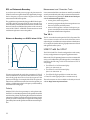
Operating Instructions USW-1P Self-Powered Subwoofer (Serial Numbers 981000 and above) Copyright © 1997 Meyer Sound Laboratories, Inc. All rights reserved PN: 05.078.008.01 B Keep these important operating instructions. Contents Introduction .......................................................... 3 AC Power ............................................................. 3 The Modular Rear Panel ....................................... 5 Amplification, Limiting, and Cooling System ..... 6 Rigging .................................................................. 6 Full-Range Systems .............................................. 7 Verifying Driver Polarity ..................................... 9 Troubleshooting ............................................... 1 0 Safety Summary ............................................. 1 1 Rear Panel and Input Modules Drawings ....... 1 2 Dimensions ........................................ Back Cover Symbols Used These symbols indicate important safety or operating features in this booklet and on the chassis. Dangerous voltages: risk of electric shock Important operating instructions Frame or chassis Protective earth ground Pour indiquer les risques résultant de tensions dangereuses Pour indequer important instructions Masse, châssis Terre de protection Zu die gefahren von gefährliche spanning zeigen Zu wichtige betriebsanweisung und unterhaltsanweisung zeigen Rahmen oder chassis Die schutzerde Para indicar azares provengo de peligroso voltajes Para indicar importante funcionar y mantenimiento instrucciones Armadura o chassis Tierra proteccionista Declaration of Conformity According to ISO/IEC Guide and EN 45014 The Manufacturer: Name: Address: Meyer Sound Laboratories, Inc. 2832 San Pablo Avenue Berkeley, California 94702-2204, USA Conforms to the following Product Specifications: Safety: EMC: EN60065: 1994 EN55103-1 emmission EN55103-2 immunity The product herewith complies with the requirements of the Low Voltage Directive 73 / 23 / EEC and the EMC Directive 89 / 336 / EEC. Office of Quality Manager Berkeley, California USA October 1, 1994 Declares that the product: Product Name: UPA-1P, UPA-2P, UM-1P, USW-1P, UM-100P Product Options: All Environmental Specifications for Meyer Sound Electronics Products: Operating temperature: 0o to + 45o Nonoperating temperature: < -40o C or > +75o C Humidity: to 95% at 35o C Operating Altitude: to 4600 m (15,000 ft) Nonoperating altitude: to 6300 m (25,000 ft) Shock: 30g 11 msec half-sine on each of 6 sides Vibration: 10 Hz to 55 Hz (0.010m peak-to-peak excursion) Made by Meyer Sound Laboratories Berkeley, California USA European Office: Meyer Sound Lab. GmbH Carl Zeiss Strasse 13 56751 Polch, Germany 2 U ® L UL LISTED 3K59 C ® COMMERCIAL AUDIO SYSTEM Introduction • suppresses high voltage transients up to several kilovolts • filters EMI (radio frequencies and noise present on the AC line) The Integrated Design • sustains operation during low-voltage periods, which minimizes audio discontinuity The Meyer USW-1P self-powered subwoofer is composed of: • two 15-inch cone drivers. • phase-corrected, optimized control electronics; • a two-channel amplifier (550 watts total). The drivers, control electronics, and amplifier are integrated into a compact enclosure. The USW-1P paired with the UPA-P Series is ideally suited for compact, high-powered PA applications, such as main PA, churches, 5.1 systems, and theatres. The USW-1P is more than a powered version of the Meyer USW-1, The powered USW-1P implements these significant design improvements: • The gain structure between the control electronics and amplifier is perfectly matched. • Theamplifierisoptimizedforthesystem,providingsubstantialpowerwithoutendangeringthedrivers. • The integrated design simplifies setup and installation, eliminates amp racks, and extends the durability and reliability of the loudspeaker. AC Power The USW-1P uses a PowerCon locking 3-pole AC mains connector that prevents inadvertent disconnection. The unit must have the correct power plug for the AC power in the area in which it will be used. Engagement Separation • provides soft-start power-up, which eliminates high inrush current The USW-1P can withstand continuous voltages up to 264V and allows any combination of voltage to GND (i.e. NeutralHot-GND, Hot-Hot-GND). Continuous voltages higher than 264V may damage the unit. Voltage Requirements The USW-1P operates safely and without audio discontinuity if the AC voltage stays within the range 88–264V, 47–63 Hz. After applying AC power, the system is muted while the circuitry charges up and stabilizes. After two seconds, the On/ Temp. LED on the user panel illuminates green, the system unmutes and is ready to pass audio signals. If the On/Temp. LED does not illuminate or the system does not respond to audio input after ten seconds, consult the Troubleshooting section. The USW-1P’s power supply uses stored energy to continue functioning for about 10 AC cycles if the voltage decreases below 88V (a condition known as brownout). The precise length of time the unit functions during brownout depends on the operating level and how low the voltage drops. The unit turns off if the voltage does not increase above 88V for 1 to 5 seconds. If the USW-1P shuts down due to brownout, the power supply automatically turns on if the voltage returns to the normal operating range. If the USW-1P does not turn back on after ten seconds, consult the Troubleshooting section. NOTE: We recommend that the supply be operated at least a few volts away from the upper and lower bounds of the operating range to avoid possible shutdown. 1 2 2 1 3 When AC power is applied to the USW-1P, an Intelligent AC supply automatically selects the correct operating voltage, allowing the USW-1P to be used internationally without manually setting voltage switches. The Intelligent AC supply performs the following protective functions to compensate for hostile conditions on the AC mains: 3 Current Requirements Power Connector Wiring Each USW-1P requires approximately 3 Arms @115V (1.5 Arms@230V) for proper operation, allowing up to five USW1P to be powered from one 15 A circuit. However, we recommend powering no more than three USW-1Ps per 15 A branch to allow a 30% margin for peak voltages. The USW-1P presents a dynamic load to the AC mains which causes the amount of current to fluctuate between quiet and loud operating levels. This affects the number of USW-1Ps that can be used for a given breaker type. Since different types of cables and circuit breakers heat up and trip at varying rates, it is essential to understand the types of current ratings and how they correspond to circuit breaker and cable specifications. Use the following AC cable wiring diagram to create international or special-purpose power connectors: The maximum continuous RMS current is the maximum RMS current over a duration of at least 10 seconds. It is used to calculate the temperature increase in cables, which is used to select cables that conform to electrical code standards. It is also used to select the rating for slow-reacting thermal breakers. • Connect the blue wire to the terminal marked with an N or colored black. The maximum burst RMS current is the maximum RMS current over a one second duration. It is used to select the rating for most magnetic breakers. The maximum instantaneous peak current during burst is used to select the rating for fast-reacting magnetic breakers and to calculate the peak voltage drop in long AC cables according to the formula V pkdrop = I pk x R total cable Use the table below as a guide to select cables and circuit breakers with appropriate ratings for your operating voltage USW-1P Current Ratings 115V 230V 100V Idle RMS 0.25A 0.13A 0.3A Max. Continuous RMS 2.8A 1.4A 3.2A Max.Burst RMS 3.2A 1.6A 3.7A Max Peak during Burst 5.0A 2.5A 5.8A To determine the minimum total service power required by a system of USW-1Ps, or other Meyer self-powered speakers, add their maximum continuous RMS currents together. We recommend allowing an additional 30% above the minimum amperage to prevent peak voltage drops at the service entry and nuisance tripping. 4 AC cable color code If the colors referred to in the diagram don't correspond to the terminals in your plug, use the following guidelines: • Connect the brown wire to the terminal marked with an L or colored red. • Connect the green and yellow wire to the terminal marked with an E (or ) or colored green (or green and yellow). Safety Issues Do not use a ground-lifting adapter or cut the AC cable ground pin. Keep all liquids away from the USW-1P to avoid hazards from electrical shock. Do not operate the unit with worn or frayed cables; replace them immediately. If the USW-1P will be installed outdoors, contact Meyer Sound for information about the optional rain hood which protects the amplifier and heat sink from rain. Weather protection for the drivers is also available. The Modular Rear Panel The rear panel of the USW-1P has two slots for modules. The top slot contains the Audio Input Module; the bottom slot contains the optional Remote Monitoring System™ (RMS) Module. A blank plate covers the bottom slot if RMS is not installed. Audio Input There are three, interchangeable Audio Input Modules with optimized connectors and controls for different applications. Each module has a 24V Fan connector to power an optional fan (see fan section on page 6). Each module uses a three-pin, female XLR audio input connector with a 10 kΩ balanced input impedance wired with the following convention: Pin 1 — 220 kΩ to chassis and earth ground (ESD clamped) Pin 2 — Signal+ Pin 3 — Signal- Case — Earth (AC) ground and chassis Differential Inputs Pins 2 and 3 carry the input as a differential signal. Use standard audio cables with XLR connectors for balanced signal sources. A single audio source can drive multiple USW1Ps with a paralleled input loop, creating an unbuffered hardwired loop connection, with negligible loss in signal level. For example, since the input impedance of one USW-1P is 10 kΩ, looping 20 USW-1P produces a balanced input impedance of 500Ω. With a 150Ω audio source, the 500Ω load results in only a 2.28 dB loss. For drawings of the modules refer to page 12. Looping, Polarity, and Attenuating Audio Input Module This module has a balanced, female XLR audio input connector, a male XLR loop connector, an input polarity switch, and a level attenuator knob. The input polarity switch offers a convenient method of reversing the polarity of the speaker. When the input polarity switch is in the up (+) position, pin 2 is hot relative to pin 3, resulting in a positive pressure wave when a positive signal is applied to pin 2. When the switch is down (-), pin 3 is hot relative to pin 2, resulting in a positive pressure wave when a positive signal is applied to pin 3. The level attenuator knob operates between 0 dB (no level attenuation) in a fully clockwise position to –12 dB in a fully counterclockwise position. Remote Monitoring System The USW-1P can be equipped to operate with the Remote Monitoring System (RMS) network and software application. RMS displays signal and power levels, driver status. limiter activity, the state of the polarity switch, attenuator level, and amplifier temperature for all speakers in the network on a Windows-based PC. RMS can also be configured to enable speaker muting. RMS is an excellent fielddiagnostic tool that removes the guesswork from troubleshooting during a performance. All Meyer Speakers with RMS can be integrated on the same network. Installing an RMS module requires only a Phillips screwdriver. Contact Meyer Sound for more information about RMS. Amplification, Limiting, and Cooling System Looping Audio Input Module This standard module uses a balanced, female XLR connector for audio input and a male XLR loop connector to interconnect multiple speakers. The audio input connector is hardwired with pin 2 hot to comply with audio industry standards. The loop connector, wired in parallel to the audio input, transmits the input signal even if the USW-1P is turned off for any reason. Summing Audio Input Module This module has two balanced female XLR connectors. The second female XLR connector functions as a summing input. Applying a signal to one of the inputs results in a normal signal level. Utilizing both summing inputs creates a correctly summed mono signal with each input 6 dB below the level of a single input. This is an effective method for distributing both sides of a stereo signal to a single USW-1P without requiring external level control. Amplification and Limiting Each driver in the USW-1P is powered by one channel of a proprietary Meyer Sound amplifier utilizing complementary power MOSFET output stages (class AB, bridged). The USW-1P employs two separate methods of limiting: Excursion Limiting which protects the drivers from over excursion and Sub Channel Limiting which prevents the drivers from damage due to thermal overload. Limiter activity for the Excursion and Sub channel is indicated by two yellow Limit LEDs on the rear panel (the EXC. Limit LED is above the SUB limit LED). See page 12 for a diagram of the user panel. The USW-1P performs within its acoustical specifications and operates at a normal temperature if the limit LEDs are on for no longer than two seconds, and off for at least one second. 5 If either LED remains on for longer than three seconds, that channel incurs these consequences: • Increasing the input level will not increase the volume. • The system distorts due to clipping and nonlinear driver operation. While the USW-1P limiters fully protect the system under overload conditions and exhibit smooth sonic characteristics; we recommend that you do not intentionally drive the USW-1P into continuous limiting to attain compression effects. For applications where large amounts of compression are required, we recommend using an outboard compressor/limiter for greater control of limit and compressor effects. Amplifier Natural Convection Cooling System The USW-1P’s amplifier employs a natural convection cooling system that is cooled by the air flowing over the heatsink. Allow for proper ventilation of fresh air when using the speaker in tightly packed conditions. If the temperature of the heatsink reaches 85°C (185°F), the On/Temp. LED on the rear panel turns from green (On) to red (Temp.) and the limiter threshold is lowered to a safe level to prevent the system from overheating. Under high temperature conditions the output level is reduced 6 dB. When the heatsink temperature decreases to 75°C (167°F), the On/Temp. LED changes from red to green and the limiter threshold returns to normal. The heatsink reaches temperatures up to 185°F (85°C) during normal operation. Use extreme caution when approaching the rear of the cabinet. Fan Assembly Kit While convection cooling is adequate for most applications, USW-1Ps when driven into continuous limiting under severe temperature conditions, or where ventilation is restricted, may benefit from the optional fan kit which increases air flow to maintain a safe operating temperature. The easy-to-install fan, powered by the 24V Fan rear panel connector, blows air directly onto the heatsink. The fan speed increases as the heatsink temperature rises, which maintains a safe operating temperature with minimal fan noise. Contact Meyer Sound to order the fan kit. 6 Power Supply Fan The power supply is cooled by a single small internal fan that turns on low when the unit is first powered up. The fan doubles its speed as the system is driven with audio. Since the fan draws air in from, and exhausts it out the back of the cabinet, there must be at least six inches clearance behind the cabinet, and adequate air flow. Rigging The USW-1P weighs 137 lb (62 kg). The maximum recommended load for an USW-1P with aircraft pan fittings is 420 lb (191 kg). This working load is based on a 5:1 safety factor. The USW-1P has three rigging plates on top; each plate is capable of supporting the full working load of the cabinet. There are four types of interchangeable rigging plates, each fastened by six Phillips screws: • aircraft pan fittings (ring and stud) • 3 /8”-16 nut plates • M-10 x 1.5 metric nut plates • blank plates (if no rigging brackets are requested) NOTE: Units with nut plates are rated for the weight of one cabinet only. Rigging load ratings assume a straight tensile pull and that the cabinet is in new condition with aircraft pan fittings. If these conditions are not met, the load ratings can be reduced significantly. Load ratings can also be reduced by age, wear, and damage. It is important to inspect the rigging hardware regularly and replace worn or damaged components immediately. NOTE: All Meyer Sound products must be used in accordance with local, state, federal, and industry regulations. It is the owners and/or users responsibility to evaluate the reliability of any rigging method for their application. Rigging should be done only by experienced professionals. Full-Range Systems Introductory Concepts The USW-1P is used to add low frequency SPL to sound systems. It is optimized to be used with the Meyer UPA-P series self-powered loudspeakers. It can also be used with all Meyer Sound loudspeakers. For information on integrating the USW-1P with the UPA-P, see the UPA-P Series Operating Instructions. For information on using the USW-1P with other Meyer Sound products please contact Meyer Sound Technical Support. Using the USW-1P in a full-range system is straight forward but the following concepts are important to consider before installing a system. 12 dB low frequency gain compared to free field. A USW-1P placed on the floor in a corner (one-eighth space loading) will gain approximately 18 dB compared to its free field response. Room Loading The placement of the USW-1P in a room or a space is critically important to the response of the speaker system. A USW-1P hung in the air with no boundary conditions would not add any SPL from room loading. A USW-1P placed on a floor (half-space loading) will gain approximately 6 dB compared to its free field response. 18 dB low frequency gain compared to free field. 6 dB low frequency gain compared to free field. A USW-1P placed on a floor and against a wall (quarter-space loading) will gain approximately 12 dB compared to its free field response. 7 SPL vs. Distance to Boundary Measurement and Correction Tools As we have seen on the previous page, the placement of a USW-1P on a floor or against a boundary significantly changes the low frequency response when compared to free field measurement of the same speaker. It is recommended that even the most carefully assembled sound systems be analyzed with precise measurement tools. We recommend using the Meyer SIM® Sound Analyzer and CP-10 Parametric Equalizer to The graph below represents the change in dB SPL for frequencies under 125 Hz of a single USW-1P as it is moved away from a boundary. Distance measured in meters, is based on the distance from the wall behind the speaker to the acoustical center of the USW-1P. All dB SPL measurements are made with the microphone on axis to the speaker. • choose, place, and array speakers; • measure propagation delays between speakers to set the correct polarity and delay times; • measure and equalize variations in frequency response caused by the acoustical environment and the placement and interaction of speakers. The VX-1: Distance to Boundary vs. dB SPL below 125 Hz dB SPL relative to free-space response. 4 2 USW-1P with the UPA-P 0 The USW-1P and UPA-P can be configured in a wide variety of array configurations to suit specific application needs. -2 Refer to the UPA-P Operating Instructions for recommended arrays; or for additional system design ideas, contact Meyer Sound for the following TechNotes documents on UPA-P array design: -4 -6 -8 0 0.5 1 1.5 2 2.5 3 3.5 4 4.5 Distance in meters between wall and acoustical center of speaker. To better understand the graph above, imagine a USW-1P with a wall behind it. As you move the USW-1P away from the wall the graph above shows how the response of the speaker will change. For example if the USW-1P is placed 1 meter from a wall and is measured on axis to the speaker, you will see a -5 dB change in the low frequency as illustrated by the dotted lines on the graph. Polarity With the USW-1P in close-proximity to, and coplanar with, the UPA-P, or other Meyer Speakers, both speakers should be set to the same polarity. Separating the subwoofers and main cabinets in a speaker system by more than 5 feet may require polarity reversal or a delay line to compensate for the propagation delay between the speakers and the measurement position. 8 The VX-1 is an ideal control option for USW-1P systems. The VX-1 is a stereo virtual crossover which allows the user to adjust the gain, switch between stereo and mono distribution of two inputs and make shelving EQ adjustments to the left and right sides of the system. • Two UPA-1Ps @ 70° Horizontal Splay (Doc #: 01.990.101.90 A) • Two UPA-1Ps @ 85° Horizontal Splay (Doc #: 01.990.101.91 A) • Two UPA-2Ps Tight-pack (Doc #: 01.990.101.92 A). • Three UPA-2Ps Tight-pack (Doc #: 01.990.101.93 A). These documents are also available on the Meyer Sound website: http://www.meyersound.com. Polarity within a USW-1P Verifying Driver Polarity Incorrect driver polarity impairs system performance and may damage the drivers. All Meyer loudspeakers are shipped with the drivers in correct alignment. Polarity In Adjacent Loudspeakers Use the following test procedure to verify the polarity between two USW-1P. 1. Establish a reference USW-1P, a speaker that has not been tampered with or damaged. Mark this speaker as the reference. 2. Place the USW-1P you want to test next to the reference USW-1P. 3. Place a measurement microphone 3 feet from the speakers on the axis between the speakers. See drawing at bottom of page. 4. Connect a signal source to reference speaker and note the frequency response and overall level. 5. Apply the same signal to the USW-1P under test with the first speaker still connected. If the driver or circuit wiring has been removed or disassembled it is essential to check the polarity between drivers and between adjacent loudspeakers. Use the following test procedure to verify polarity between drivers in the same loudspeaker : 1. Place the reference USW-1P and the USW-1P under test side to side so that the drivers are facing the same direction. 2. Place a measurement microphone 3 feet from the speakers on the axis between the speakers. See drawing at bottom of page. 3. Connect a full range signal to the reference USW-1P loudspeaker and note the frequency response and sound pressure level. 4. Compare the reference and test USW-1P results one at a time. A significant decrease in energy from 40 to 100 Hz in the USW-1P under test indicates a driver reversal. Contact Meyer Sound Technical Support for information on Service Center or field correction. 5. If the reference and USW-1P under test have similar responses, then there is no internal polarity error within the loudspeaker. The polarity is correct if the frequency response remains constant with a 5 to 6 dB SPL increase in amplitude. Broadband cancellation (decreased overall level) indicates polarity reversal between cabinets. A 2 to 3 dB SPL increase may indicate that one of the drivers in the USW-1P under test is out of phase, in this case, proceed to the next section. Reference USW-1P Front of Speaker Since polarity reversal causes excessive driver excursion at high source levels, use moderate levels when conducting these tests. 3 feet USW-1P under test Front of Speaker Microphone 9 Troubleshooting This section suggests several possible solutions to some common problems encountered by USW-1P users and is not intended to be a thorough troubleshooting guide. Contact Meyer Sound for additional information and documentation. The On/Temp. LED does not illuminate, there is no audio, and the power supply fan is off. 1. Make sure the AC power cable is the correct type for the regional voltage and that it is securely connected to the AC inlet then unplug and reconnect the AC cable. 2. Use an AC voltmeter to verify that the AC voltage is within the ranges 88–264V, 47–63 Hz. 3. Call Meyer Sound Technical Support. The On/Temp. LED is illuminated but there is no sound. 1. Verify that the audio source (mixer, EQ, delay) is sending a valid signal. 2. Make sure the XLR cable is securely fastened to the XLR audio input connector. 3. Verify that the XLR cable is functioning by substituting another cable or by using the cable in question in a working system. 4. Send the audio signal to another speaker to insure signal presence and that the level is within the proper range. Turn the source level down before reconnecting the audio input and increase the level slowly to avoid a sudden blast of sound. 5. If possible, monitor the audio source with headphones. Hum or noise is produced by the speaker. 1. Disconnect the audio input. If the noise persists, the problem is within the USW-1P. In this case return the unit to the factory or nearest authorized service center. If the hum ceases, the noise originates somewhere earlier in the signal path. 2. Make sure the XLR cable is securely fastened to the XLR audio input connector. 3. Send the audio signal to another speaker to insure signal presence and that the level is within the proper range. Turn the source level down before reconnecting the audio input and increase the level slowly to avoid a sudden blast of sound. 5. Hum or noise can be produced by a ground loop. Since the USW-1P is effectively ground-lifted, the loop must be broken elsewhere in the system. 10 The audio produced by the speaker is distorted or compressed but the limit light is not illuminated. 1. Make sure the XLR cable is securely fastened to the XLR audio input connector. 2. Send the audio signal to another speaker to insure that the level is within the proper range. Turn the source level down before reconnecting the audio input and increase the level slowly to avoid a sudden blast of sound. 3. Monitor the audio source with headphones. The audio produced by the speaker is highly compressed and the limit light is constantly red. 1. Turn down the level of the input signal to the speaker system. There is sound but it is does not seem to be at full power and the On/Temp. LED is yellow. This occurs in conditions where the heatsink temperature reaches 85°C (185°F), indicating that the amplifier is thermally overloaded. The limiter threshold has dropped to a safe level, so the audio level is reduced. 1. Make sure there is enough clearance above, below, and behind the unit. 2. Make sure there is sufficient air flow around the unit. 3. Avoid exposing the heatsink to direct sunlight if the ambient temperature is high. 4. If the ambient temperature is greater than 30° C and this condition occurs frequently, contact Meyer Sound to order the optional Fan Kit. See the section Amplification, Limiting, and Cooling System on page 6 for a complete discussion about the cooling system. There is no sound, the On/Temp. LED is dim or off, and the power supply fan is on high speed. This extremely rare event occurs when the power supply overheats, causing a 1-2 minute interruption in operation. The unit turns on again when the power supply has cooled sufficiently. 1. Make sure there is at least six inches clearance behind the unit. 2. Make sure there is sufficient air flow around the unit. See the section Amplification, Limiting, and Cooling System on page 6 for a more information about the power supply’s internal fan and cooling system. Safety Summary English • To reduce the risk of electric shock, disconnect the loudspeaker from the AC mains before installing audio cable. Reconnect the power cord only after making all signal connections. • Connecttheloudspeakertoatwo-pole,threewiregroundingmains receptacle. The receptacle must be connected to a fuse or circuit breaker. Connection to any other type of receptacle poses a shock hazard and may violate local electrical codes. • Do not install the loudspeaker in wet or humid locations without using weather protection equipment from Meyer Sound. • Do not allow water or any foreign object to get inside the loudspeaker. Do not put objects containing liquid on, or near, the unit. Français • Pour réduire le risque d’électrocution, débrancher la prise principale de l’haut-parleur, avant d’installer le câble d’interface allant à l’audio. Ne rebrancher le bloc d’alimentation qu’après avoir effectué toutes les connections. • Branchez l’haut-parleur dans une prise de courant à 3 dérivations (deux pôles et la terre). Cette prise doit être munie d’une protection adéquate (fusible ou coupe-circuit). Le branchement dans tout autre genre de prise pourrait entraîner un risque d’électrocution et peut constituer une infraction à la réglementation locale concernant les installations électriques. • Ne pas installer l’haut-parleur dans un endroit où il y a de l’eau ou une humidité excessive. • To reduce the risk of overheating the loudspeaker, avoid exposing it to direct sunlight. Do not install the unit near heat emitting appliances, such as a room heater or stove. • Ne pas laisser de l’eau ou tout objet pénétrer dans l’hautparleur. Ne pas placer de r´cipients contenant un liquide sur cet appareil, ni à proximité de celui-ci. • This loudspeaker contains potentially hazardous voltages. Do not attempt to disassemble the unit. The unit contains no user serviceable parts. Repairs should be performed only by factory trained service personnel. • Pour éviter une surchauffe de l’haut-parleur, conserver-la à l’abri du soleil. Ne pas installer à proximité d’appareils dégageant de la chaleur tels que radiateurs ou appareils de chauffage. Deutsch • Ce haut-parleur contient des circuits haute tension présentant un danger. Ne jamais essayer de le démonter. Il n’y a aucun composant qui puisse être réparé par l’utilisateur. Toutes les réparations doivent être effectuées par du personnel qualifié et agréé par le constructeur. Español • Um die Gefahr eines elektrischen Schlages auf ein Minimum zu reduzieren, den Lautsprecher vom Stromnetz trennen, bevor ggf. ein Audio-Schnittstellensignalkabel angeschlossen wird. Das Netzkabel erst nach Herstellung aller Signalverbindungen wieder einstecken. • Para reducir el riesgo de descarga eléctrica, desconecte de la red el altoparlante antes de instalar el cable de señalización de interfaz de la segnale. Vuelva a conectar el conductor flexible de alimentación solamente una vez efectuadas todas las interconexiones de señalizatción. • Der Lautsprecher an eine geerdete zweipolige DreiphasenNetzsteckdose anschließen. Die Steckdose muß mit einem geeigneten Abzweigschutz (Sicherung oder Leistungsschalter) verbunden sein. Der Anschluß der unterbrechungsfreien Stromversorgung an einen anderen Steckdosentyp kann zu Stromschlägen führen und gegen die örtlichen Vorschriften verstoßen. • Conecte el altoparlante a un tomacorriente bipolar y trifilar con neutro de puesta a tierra. El tomacorriente debe estar conectado a la protección de derivación apropiada (ya sea un fusible o un disyuntor). La conexión a cualquier otro tipo de tomacorriente puede constituir peligro de descarga eléctrica y violar los códigos eléctricos locales. • Der Lautsprecher nicht an einem Ort aufstellen, an dem sie mit Wasser oder übermäßig hoher Luftfeuchtigkeit in Berührung kommen könnte. • Darauf achten, daß weder Wasser noch Fremdkörper in das Innere den Lautsprecher eindringen. Keine Objekte, die Flüssigkeit enthalten, auf oder neben die unterbrechungsfreie Stromversorgung stellen. • Um ein Überhitzen dem Lautsprecher zu verhindern, das Gerät vor direkter Sonneneinstrahlung fernhalten und nicht in der Nähe von wärmeabstrahlenden Haushaltsgeräten (z.B. Heizgerät oder Herd) aufstellen. • Im Inneren diesem Lautsprecher herrschen potentiell gefährliche Spannungen. Nicht versuchen, das Gerät zu öffnen. Es enthält keine vom Benutzer reparierbaren Teile. Reparaturen dürfen nur von ausgebildetem Kundenienstpersonal durchgeführt werden. • No instale el altoparlante en lugares donde haya agua o humedad excesiva. • No deje que en el altoparlante entre agua ni ningún objeto extraño. No ponga objetos con líquidos encima de la unidad ni cerca de ella. • Para reducir el riesgo de sobrecalentamiento, no exponga la unidad a los rayos directos del sol ni la instale cerca de artefactos que emiten calor, como estufas o cocinas. • Este altoparlante contiene niveles de voltaje peligrosos en potencia. No intente desarmar la unidad, pues no contiene piezas que puedan ser repardas por el usuario. Las reparaciones deben efectuarse únicamente por parte del personal de mantenimiento capacitado en la fábrica. 11 Rear Panel and Optional Modules The user panel and optional modules are described on page 5 of this guide. Fan Connectors Rain Hood screw GND Circuit Rain Hood screw 1 2 3 1 2 3 Looping Audio Input Push Limit 220k Ω Case Female XLR Input Male XLR Loop Hi Limit LED Low Limit LED 24VFan - Earth / Chassis Input + Remote ity et k RMS LEDs Network A ct iv es in R W Service Monitor RMS Network Connectors System CAUTION : See instruction manual ATTENTION : Voir le cahier d'instruction ! On/Temp. LED On / Temp. Loop AC Input 100-240V 50-60Hz 4A MAX ~ Meyer Sound, Berkeley, CA. USA PowerCon Locking AC Mains Inlet UX RATING LABEL A/W 30.076.069.01, REVISION. A 11/12/97 cmc Rain Hood screw Rain Hood screw User Panel with RMS option and Standard Looping Audio Input Module. High Limit LED GND Circuit 1 2 3 1 2 3 Push 10k Ω Balanced Ω + Looping Polarity & Attn. Audio Input - Attn dB -6 Push 220k Ω -9 Case Low Limit LED Limit -3 24VFan - Earth / Chassis + + - 0 Polarity Loop Input -12 On / Temp. Looping, Polarity, and Attenuating Input Module High Limit LED GND Circuit 1 1 1k Ω Each Push 25k Ω Balanced Ω + - Ω Each 2 2 Push Limit 220k Ω 3 3 Case 24VFan - Earth / Chassis Inputs + Summing Inputs Summing Audio Input Module 12 Low Limit LED Summing Audio Input On / Temp. ! Front Sides 220k Ω Case Push Loop Service 1 2 3 - 24VFan Remote + Looping Audio Input CAUTION : See instruction manual ATTENTION : Voir le cahier d'instruction Monitor System Network On / Temp. Limit Meyer Sound, Berkeley, CA. USA AC Input 100-240V 50-60Hz 4A MAX ~ CAUTION Earth / Chassis Back Meyer Sound Laboratories, Inc. 2832 San Pablo Avenue Berkeley, California 94702 Telephone: 510 - 486 - 1166 FAX: 510 - 486 - 8356 E-mail: [email protected] http://www.meyersound.com 13 This equipment must be grounded. RISK OF ELECTRIC SHOCK-- DO NOT OPEN ! or electric shock do not expose this appliance to rain or moisture. WARNING: To reduce the risk of fire SOLO AUTORIZADO A PERSONAL TÉCNICO CALIFICADO WARTUNG UND REPARATUR NUR DURCH ELEKTROFACHKRÄFTE INTERNES NE SONT AUTORISEES QU'AU PERSONNEL TECHNIQUE QUALIFIÉ while in use. To ensure proper operation, allow at least 6 inches clearance from this surface and adequate ventilation. HOT CAUTION CALIENTE CHAUD HEISS The wires in this mains lead are coloured in accordance with the following code --green-and-yellow: earth --blue:neutral --brown: live WARNINGS: THIS APPARATUS MUST BE EARTHED. IMPORTANT: CAUTION: The heatsink surface may reach high temperatures ! 21.56 ATENCIÓN: ACCESO INTERNO ACHTUNG: GEHÄUSE NICHT ÖFFNEN ATTENTION : E N T R E T I E N E T R E P A R A T I O N S 1 2 3 y ! ! Screw for fan Screw for fan 9.77 11.00 Screw for fan Screw for fan k Input set GND Circuit ivit C L 31.00 Win 14.00 ± .12 Re 12.75 ± .12 Typical Act Dimensions (in inches) Top 15.50 2.63 11.00 21.30 19.25 11.88 11.00