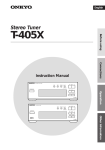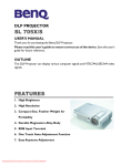
1
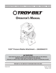
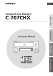
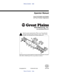
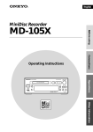
NGP SERIES PISTON METERING PUMP PARTS AND INSTRUCTION MANUAL NGP-6055 Shown CDS-JOHN BLUE COMPANY DIVISION OF ADVANCED SYSTEMS TECHNOLOGY, INC. 165 Electronics Blvd, Huntsville, AL 35824 Telephone: (256) 721-9090 - FAX: (256) 721-9091 Toll Free: 1-800-253-2583 Printed in U.S.A. 12-M-43 Rev 02/15 SAFETY PRECAUTIONS Equipment should be operated only by responsible people. A careful operator is the best insurance against an accident. Fill system with WATER first and check output. Check all valves, fittings, hose clamps, etc. for wear / leaks before admitting process fluid to the system. Replace hoses when worn, cracked, or if leaking. WARNING: USE OF THIS PRODUCT FOR ANY PURPOSES OTHER THAN ITS ORIGINAL INTENT, ABUSE OF THE PRODUCT, AND/OR MODIFICATION TO THE ORIGINAL PRODUCT IS STRICTLY PROHIBITED BY CDS-JOHN BLUE COMPANY. CDS-JOHN BLUE COMPANY RESERVES THE RIGHT TO DENY WARRANTY OR LIABILITY CLAIMS IN ANY/ALL SITUATIONS INVOLVING MISUSE, ABUSE OR MODIFICATION. THE ORIGINAL INTENT OF THIS PRODUCT DOES NOT INCLUDE USE WHERE THE MAXIMUM ALLOWED SPEED, PRESSURE, OR TEMPERATURE IS EXCEEDED, AND IT DOES NOT INCLUDE APPLICATIONS UTILIZING FLUIDS THAT ARE NOT COMPATIBLE WITH THE PRODUCT’S COMPONENT MATERIALS. DO NOT USE THIS PRODUCT WITH FLAMMABLE OR COMBUSTIBLE FLUIDS SUCH AS GASOLINE, KEROSENE, DIESEL, ETC…, AND DO NOT USE IN EXPLOSIVE ATMOSPHERES. FAILURE TO FOLLOW THIS NOTICE MAY RESULT IN SERIOUS INJURY AND/OR PROPERTY DAMAGE AND WILL VOID THE PRODUCT WARRANTY. IF IN DOUBT ABOUT YOUR APPLICATION, CONTACT YOUR STOCKING DEALER OR THE CDS-JOHN BLUE TECHNICAL STAFF AT 1-800-253-2583. Important Message to Owners / Operators of Pumps Equipped with Lever Actuated Throw Out Clutches When using a pump operated by a lever actuated throw out clutch, the rope must be routed by use of eyelet pulleys such that the rope cannot become entangled with or come in contact with any moving parts of the tractor or the applicator such as PTO shafts, tractor tires, ground drive units, etc. If eyelet pulleys are not found packed in with the pump, please contact your selling agent or CDS – John Blue Company (1-800-253-2583) immediately before any operations are undertaken. Verification must be made prior to any operation that the rope is clear of any moving parts while not only driving straight but when making turns either right or left. Verification must be made prior to any operation that the properly routed rope contains no loops, which might become entangled with any part of the equipment or operator. At no time should the rope be attached to any clothing worn by or to any body parts of the operator such as hands, arms, legs, etc. We fully understand these are normal precautions owners / operators should take prior to and while operating equipment. However, we wish to remind you that failure to comply with all safety regulations regarding instructing operators in the use of moving equipment and actual operation of the equipment may lead to serious injury and possible death. To The Owner This manual has been prepared and illustrated to assist you in the maintenance of your CDS – JOHN BLUE PUMP. Enter your serial number and the date of the purchase in the space provided below for future reference in service information or for ordering parts. Because our engineering department is constantly improving products, we reserve the right to make design and specification changes without notice. Model Number: ________________ Serial Number: ________________ Purchase Date: ________________ © 2015 CDS-John Blue Co. 2 TABLE OF CONTENTS Safety Precautions ………………………………………………………………………………………………… 2 Note to the Owner …………………………………………………………………………………………………. 2 Table of Contents …………………………………………………………………………………………….……. 3 Pump Specifications ……………………………………………………………………………………….……… 3 Introduction ………………………………………………………………………………………………….……… 4 Installation …………………………………………………………………………………………………..……… 5 Pump Setting ……………………………………………………..………………………………………….....…. 6 Initial Start-Up of Pump ……………………………………………….…………………………………….……. 8 Pump Calibration …………………………………………………….………………………………………….... 8 Pump Accuracy ……………………………………………………………………………………………………. 8 Maintenance ……………………………………………………………………………..……………………..….. 9 Storage …………………………………………………………………………..…………………………………. 9 Service Maintenance ………………………………………………………………..…………………………..… 10 Crankcase Disassembly …………………………………………………………………….………………..…… 12 Parts List NGP-6050 & NGP-7050 [Single Piston] ………………………………………………………….…. 14 Parts List NGP-8050 & NGP-9050 [Double Piston] ……………………………………………..…………….. 16 Parts List for Double Adjustable Double Piston ………………...………………………………..…………….. 18 Parts List Optional Clutch ……………………………………………………………………………………...…. 19 Dimensional Footprints ………………………………………………………………………………….………… 22 Trouble Shooting …………………………………………………………………………………………....…….. 23 Warranty ……………………………………………………………………………………………………....……. 24 PUMP SPECIFICATIONS Universal Specifications Operating Pressure: MAX 120 PSI Operating Speed: MAX 450 RPM Rotation: Clockwise or Counter-clockwise Drive: No. 50 Roller Chain Crankcase Lubrication: SAE 90 Gear Oil Grease Zerks: Multipurpose Grease H L W Model Specifications Pump Series: NGP-4055 NGP-5055 NGP-6050 NGP-7050 NGP-8050 NGP-9050 Output Volume 10.2 20.4 21.0 34.2 42.0 68.4 Max Gal/Min Output Disp. .023 .046 .047 .076 .093 .152 Max Gal/Rev Required H.P. 1.10 2.20 2.25 3.00 4.50 6.00 Theoretical Physical Dims. 10x16x9 14x16x9 10x15x9 10x19x11 14x15x11 Weight 65 125 65 105 125 155 Lbs. Crankcase Oil Cap. 0.5 2.5 0.5 1.5 2.5 5.4 Pints Inlet/Outlet Ports 1” 1” 1-1/2” 1-1/2” 1-1/2” 1-1/2” 200 200 220 220 220 220 Optional Flanges © 2015 CDS-John Blue Co. 3 14x19x13 W x L x H (in.) Female Pipe Thd Flange Size INTRODUCTION The NGP series pump is a positive displacement variable stroke metering pump. It is specifically designed to accurately meter liquid fertilizer solutions. The pump’s construction is of rigid thick walled cast iron cylinders and manifolds for durability and long life. The check valves, piston, and rod are constructed of stainless steel for improved corrosion resistance. Optionally, the pump may be purchased with stainless cylinders and manifolds. The NGP series pump functions as a positive displacement metering device which operates in direct relation to the ground speed through a ground drive system (model number DRV-3xxx). The application rate can be set (covered under the “Pump Setting” section) before application begins and the GPA (gallons per acre) application will be accurate regardless of the varying speeds of the drive mechanism. The NGP series pump may also be used with one of our hydraulic drive kits (model number VRH-xxx-xx) to provide variable rate application when used with one of many different control systems. The pump provides several advantages over other types of pumps such as: suction capability from saddle tanks, stable settings that do not vary with temperature, and proven durability and longevity. The NGP series pump is designed to control the overall gallons of solution metered over an acre, independent of downstream discharge pressure (120 psi max). The only function of the flow divider or row orifices in a CDS – John Blue pump system is to divide liquid accurately row to row - not to meter the overall application rate. Sprocket Discharge Port Oil Fill Plug Vent Plug Oil Level Plug Optional Flanges Shown Rear - Not Shown Oil Drain Plug Rear - Not Shown Rod Packing Piston Discharge Valves Top Position (Stiff Spring, Flat Side In) Pump Setting Hub & Pointer Not Visible Packing Grease Zerk Piston Packing Suction Valves Bottom Position (Weak Spring, Flat Side Out) © 2015 CDS-John Blue Co. Valve Access Cover Suction Port 4 INSTALLATION MOUNTING The NGP pump should be mounted on a rigid base in a horizontal position. The mount position should allow for a straight drive chain and proper tightness. Chain idlers should be installed on the slack side of the drive chain. The supplied rubber washers are installed between the pump and mount. Caution should be exercised on implements with wings or folding members to assure that sufficient area is allowed around the pump and plumbing to not cause contact or binding. Verify that the rear tractor wheel will clear the pump during sharp turns. The oil vent plug should be installed in the oil fill located on top of crankcase. SUCTION PLUMBING An adequately sized 30 mesh strainer should be installed on the suction side of the pump and should be checked at each tank filling for debris, which could cause suction restriction, starving the pump of flow. The NGP pump does produce suction to pull fluid from the tank; however, it is recommended to mount the pump level or below the tank, if possible, to assure the most effective and quickest prime. Install the process fluid suction line as straight as possible avoiding restrictions from kinks or extremely sharp turns. This will ensure even flow during maximum pump output. Quick connect fittings should be checked and double checked to verify that no leakage is present. Quick connects, although commonly necessary, quite often can produce a suction leak if installed in a bind allowing air to enter the pump, causing loss of prime and / or reduction in pump output. It is recommended that suction line hoses be double clamped. Again, this is an area that can produce a suction air leak into the pump, even if no drip from the hose is present. DISCHARGE PLUMBING It is not recommended to install a discharge strainer as these could clog with debris causing significant discharge pressure and possible system damage in positive displacement pump applications. Flow dividers may be installed either directly on top of the discharge port or remote mounted. Orifice applications must pay particular attention for proper orifice sizing for the specified application rate. It is recommend that applications using a double piston pump with two flow dividers remove the common manifold and plumb each flow divider independently to each piston to assure accuracy. On – The – Go Variable Rate applications require that a CDS – John Blue Co. flow divider distribution manifold be used that will automatically and accurately adjust for varying on the go rate changes. WARNING: The flow range of a NGP pump far exceeds the flow curve of a single orifice operating below 120 psi. For Example: An orifice application at 30 psi discharge pressure for a rate of 20 GPA @ 4 mph will produce 422 psi when the rate is adjusted to 50 GPA and ground speed increased to 6 mph. © 2015 CDS-John Blue Co. 5 PUMP SETTING The NGP pump output is determined by the drive sprocket ratio and the stroke setting. There are two ways to find the proper setting for your pump: 1. Using the online flow rate calculator at www.cds-johnblue.com .The icon is on the right-hand side of the page, and there is a mobile version available here: 2. Using the slide chart (115698-91) supplied with the pump – follow the example below: SPROCKET RATIO LOADED RADIUS STANDARD SPROCKET COMBINATIONS MAXIMUM GROUND SPEED GALLONS PER ACRE PUMP SETTING SWATH WIDTH SPROCKET RATIO Standard Sprocket Combinations Standard sprocket combinations may be used for equipment with only one chain from the ground or press wheel sprocket to the pump sprocket. For example: an applicator with a 60 tooth drive sprocket on the tire driving a 16 tooth driven sprocket on the pump can use the 16 to 60 mark on the slide chart. Non-Standard Sprocket Combinations If you are using sprocket combinations with multiple sprockets, such as with a jack shaft, use the following formula to determine sprocket ratio: Drive Sprocket = Sprocket Ratio Driven Sprocket For example: an applicator with a 50 tooth on the drive wheel, driving to a 24 tooth on the jack shaft, then a 36 tooth on the jack shaft driving up to a 16 tooth pump driven sprocket, would yield a 4.69 drive ratio. 50 T (@ Drive Wheel) 24 T (@ Driven Shaft) X 36 T (@ Drive Shaft) 16 T (@ Driven Pump) = 50 36 X 24 16 = 4.69 Sprocket Ratio Set the sprocket ratio on the slide chart using the 4.69 calculation for the example above. © 2015 CDS-John Blue Co. 6 LOADED RADIUS The measurement for the loaded radius must be from the Manufacturer of the tire or be measured under loaded conditions. The loaded radius tire is always the tire that has the first drive sprocket attached to its hub. Ground Wheel Drive Arrangement Measure the loaded radius from the center of the hub to the bottom of the tire where it rests on the ground. Press Wheel Drive Arrangement Measure the loaded radius from the center of the press wheel shaft to where the wheel rests against the tire. The press wheel must be engaged for normal operation to give an accurate reading. SWATH WIDTH To determine the swath width, count the number of outlets and multiply by the distance (inches) between any two outlets, nozzles, or shanks. This assumes that all outlets are equally spaced, if outlets are not evenly spaced, figure the entire length of the boom or toolbar from end nozzle to end nozzle and allow for coverage beyond the ends. For example, an 11 row boom at 30” would have a swath width of 330” SETTING THE PUMP Read the desired pump setting from the bottom scale on the pump setting chart. Loosen the setting pointer nut and rotate the setting hub until the setting pointer is over the desired setting. The setting wrench will facilitate rotation of the setting hub. Once proper pump setting is achieved, tighten the setting pointer nut. EXAMPLE: An applicator is equipped with a NGP-6050 series pump, 11L x 15” tires, a 60 tooth drive sprocket, and a 16 tooth pump driven sprocket. It is desired to apply 33 gallons per acre on a 360” swath. The following steps will determine correct pump setting: 2 SET SWATH WIDTH AT DIAMOND 1. Set loaded radius of tire (13.5”) under the sprocket combination of 16 to 60 in the top window. 2. Set the swath width (360”) under the diamond in the middle window. 3. Read that the pump setting is approx. 9 at 33 gallons per acre on the NGP-6055 scale in the bottom window. 4. Set the pump to setting 9 to achieve 33 gallons per acre Note: The max. ground speed is read above the diamond as 3 approx. 9 mph to avoid exceeding 450 pump rpm. © 2015 CDS-John Blue Co. 7 READ PUMP SETTING 1 SET LOADED RADIUS AT SPROCKET RATIO INITIAL PUMP START UP Verify that all installation guidelines have been followed as outlined in the installation section of this manual. Fill the tank full of water to test for leaks in the plumbing system and output of the pump. Fully open the valve at the tank allowing water to fill the suction line and check for leaks. Set the pump to pump setting 10. Before installing nozzles or orifices (if used), prime the pump and purge the system of air and foreign material by slowly pulling the applicator 100 to 200 yards. Turn off the valve at the tank, open strainer, check for foreign material and clean the screens. The CDS – John Blue flow divider is automatic and requires no calibration; however, if nozzles or orifices are used, verify that the orifices are sized properly as to not produce high discharge pressure. Pull the machine over known acreage and verify the application accuracy with water prior to field application of chemical. Note that tank level marks can give false readings if read on uneven ground. PUMP CALIBRATION The NGP pump is calibrated from the factory; however, if the setting scale, hub, or pointer is replaced, use the following procedure to calibrate the pump output with scale readings. Remove the valve cover and outboard cylinder (see maintenance section). Set the pump on pump setting 5 for all pump sizes. Rotate the crankshaft until the piston is as far in as it will go. Measure the distance from the end of the piston to the inboard cylinder flange. Rotate the crankshaft until the piston is as far out as it will go and measure again to the same place. The difference in length is the stroke length, which at pump setting 5 should be 9/16” for the NGP-4050, 5050, 6050, & 8050, or 15/16” for the NGP-7050 & 9050. If the distance is less than the required amount, reset the pointer at a higher setting, if it is greater; reset the pointer at a lower setting. Repeat this procedure to obtain the required measurement. Once accomplished, loosen the setting scale screws until the 5 is directly under the pointer and secure the scale in position with the three scale screws. Replace the outboard cylinder and valve cover, making sure that the valves are in their proper orientation as covered under the maintenance section. PUMP ACCURACY A catch test may be performed to verify accuracy (not as a calibration method) by priming the pump and catching all of the pumped fluid from the discharge for a known number of revolutions. See chart below: Pump Series Pump Setting # of Revolutions Total Pump Output NGP-4050 8-1/4 10 1-1/2 Pints NGP-5050 8-1/4 10 3 Pints NGP-6050 8 10 3 Pints NGP-7050 8-1/4 10 5 Pints NGP-8050 8 10 6 Pints NGP-9050 8-1/4 10 10 Pints © 2015 CDS-John Blue Co. 8 MAINTENANCE Check oil daily and fill crankcase to proper level with a quality grade SAE 90 weight gear oil. With the pump sitting level, the oil should be within 1/2” of the bottom of the hole on back of crankcase. You may use a long wire or zip tie as a dipstick to check the level – some length is required due to the hole’s depth. Lubricate all grease zerks on roller chain sprocket spacer, outboard cover plate, crankshaft end, and at stuffing box flange daily. Fill zerks until grease is visibly seen seeping from mating parts. For the stuffing box flange zerk, grease will be seen seeping from the vent on the opposite side of the flange. Pump oil should be changed seasonally or more often in extreme use conditions. Visually inspect sprocket and drive chain daily for excessive wear or corrosion. Lubricate chain regularly to reduce corrosion. Chain alignment must be straight. STORAGE IMPORTANT – KEEP AIR OUT AND KEEP FROM FREEZING Keep air out of the pump! This is the only way to prevent corrosion. Even for short periods of storage, the entrance of air into the pump causes RAPID and SEVERE CORROSION. Freezing temperatures can cause the fluid or water to freeze internally to the pump, which can cause severe damage to the wet-end castings. OVERNIGHT Suspension fertilizer must be flushed from the pump for ANY storage period. For Clear Liquids: 1. Steady or rising temperatures: leave pump and hoses filled with solution. DO NOT DRAIN nor admit air to the pumps. 2. Cooling weather: (solution likely to salt out), fill pump with water and leave filled. DO NOT admit air. 3. Freezing temperature: fill pump with RV-antifreeze and leave filled, DO NOT admit air. ONE TO TWO WEEKS ACCEPTABLE: Flush pump thoroughly with 5 to 10 gallons of a solution that will neutralize the liquid last pumped (refer to that manufacturer’s instructions). Fill with clean water and DO NOT DRAIN. Keep pump sealed to exclude air. If freezing temperatures are remotely possible, the winter storage procedure (see below) must be used to avoid damage to the pump castings. PREFERRED: Flush pump as detailed above. IMMEDIATELY fill all passages in pump with straight RVantifreeze which contains a rust inhibitor. Place 1-1/2” NPT PVC plugs in the suction and discharge fittings to keep pump full and exclude air. WINTER STORAGE 1. Flush pump as detailed above. 2. With pump set on 10, draw in straight RV-antifreeze until the discharge is clean. If system utilizes a flow divider (FD), pump the RV-antifreeze through the FD manifold until it is seen in the discharge lines. Fill pump and plug suction and discharge fittings of pump to retain RV-antifreeze. © 2015 CDS-John Blue Co. 9 SERVICE MAINTENANCE Proper maintenance of the NGP pump will ensure a service life for many years. Rebuilding and / or servicing check valves, piston flange packing, piston rod packing, and crankcase components is an economical way to ensure optimum service. This type of service is simple, and can be done by almost all end users. The parts list and schematic section shows the position of all service kit items, which includes all seals, packing, and gaskets. Gasket kits and component parts can be ordered through any authorized CDS – John Blue distributor. CLEAN AND INSPECT CHECK VALVES Remove the valve cap exposing all 4 check valves. Take care in removal to notice the orientation of the valves. Discharge valves use a tighter spring and are on top, flat side in. Suction valves use a weaker spring and in the bottom, flat side out. Valves should be removed by hand, do not use a screw driver or pry-bar as damage can result. Push each valve disc off its o-ring seat ensuring that the spring reseats each disc evenly and that no debris is present. Inspect the o-rings for cuts or cracks which could allow air to enter or cause the discs to not seat properly. Check the port o-rings positioned near the top and bottom of the inboard cylinder in an oval shaped groove. This o-ring should not Suction Valves Discharge Valve be removed unless visible damage is present. The o-rings should be fully installed in the groove with no cuts or cracks. Once all valves are checked for debris or damage and o-rings are in position, re-install valves in proper orientation, replace the cover, and tighten the bolts evenly. PISTON PACKINGS With valve cover removed, remove the ½” long bolts securing the outboard cylinder. Remove the outboard cylinder exposing the piston – gaskets, washer, and packing. Remove the first piston – packing, gasket, and washer; notice the orientation of the packing lip. Remove the second piston gasket and packing from the inboard cylinder; again noticing the orientation of the packing lip. Inspect the packing and replace if necessary, gaskets should always be replaced once removed. The piston - packing should be pliable and without cracks or nicks to perform properly. Clean the cavities of both the inboard and outboard cylinder as well as the valve cap while disassembled. Discoloration of the plunger and / or lateral scoring of the piston can be deceiving, but not necessarily detrimental. Piston – packing Piston – gasket Piston – washer Piston – gasket Piston - packing Inspect piston for deep grooves, radial scoring, or severe abrasion. The best method is by feel. Assemble in reverse manner taking care for proper orientation of the piston – packing, gaskets, and washer. © 2015 CDS-John Blue Co. 10 PISTON ROD PACKINGS The rod packing consists of 2 sets of self-tightening ‘V’ rings which seal around the piston rod to prevent pumped fluid from leaking and protect the crankcase from contamination. Virtually any leakage of the pumped fluid through the vent in the side of the stuffing box is an indication that these rod packing need replacement. However, it is not uncommon for oil to drip form this drain. Removal of rod packing: With the valve cap and cylinders removed, remove the piston nut and piston by rotating piston counter-clockwise, use a belt wrench Piston Rod Packing or cloth nearest to the nut end to prevent damage to the piston. Remove the stuffing box and gasket which house the wet-end piston rod packing. Remove the snap ring from the end of the stuffing box, allowing the washer, spring, and washer to slip out. The L-1031-2 insert should not be removed from the stuffing box. The rod packing set can be removed with a hook or screwdriver by prying the multipiece rod packing set out of the cavity. Once removed it must be replaced with a new service rod packing set. There is no snap ring on the second set closest to the crankcase located in the crosshead guide. This set may be removed in the same manner as the first set. There is a secondary o-ring rod seal located at the bottom of the set which also should be replaced. Inspect the piston rod for any deep scoring and replace if necessary. A polished wear pattern may be evident and is not detrimental; however, deep grooves indicate the piston rod assembly should be replaced. The crosshead guide may be removed from crankcase to allow for inspection of the connecting rod bushing. If damaged or slop is present, this should be replaced. Re-assembly and replacement of rod packing: Carefully re-install the crosshead guide and gasket and bolt to crankcase, if removed. Lubricate piston rod and install o-ring first, then carefully install the first ‘V’ ring packing set. The set consists of a bottom adapter, 4 rings, and a top adapter. Each component should be inserted one at a time and pressed firmly in place. The 4 rings have a ‘V’ shape and are oriented so as the ‘V’ point is pointed towards the crankcase, for both sets. Install the washer and spring. Install second set in the stuffing box in a similar manner, there is no secondary o-ring required in this set. Install the washer, spring, then washer and hold in place with snap ring. Lubricate piston rod and stuffing box, then slide stuffing box carefully back over rod, being extremely careful to push straight on the piston rod so as the rods threads do not damage the ‘V’ ring set. Re-assemble piston, inboard, and outboard cylinder in reverse manner. Continue with valves in proper orientation, valve cover, and secure all bolts evenly. Finally, lubricate the stuffing box grease zerk until grease seeps out of the stuffing box vent hole. © 2015 CDS-John Blue Co. 11 CRANKCASE DISASSEMBLY Major pump repair requires some in-depth knowledge on working tolerances for internal parts. We recommend that you contact your nearest CDS-John Blue sales and service dealer for best results in major pump repair. Shaft oil seals have been upgraded from previous L & LM series pumps to include a wiper ring. The oil seals are enclosed in a greaseable cavity to flush debris from around the seal, which is a contributing factor to premature oil seal failure. The oil seals may be replaced by following the OUTBOARD & INBOARD COMPONENTS section below. All instruction and visual representation in this section is shown with wet-end components removed which is covered in the maintenance sections preceding this section. OUTBOARD COMPONENTS Remove the retaining ring, pump setting hub, and pointer. Remove the flange cover exposing the oil seal in its cavity. Remove the oil seal which may be done with a screw driver, taking care not to scar the internal shaft or housing. Inspection of the stroke setting sleeve should be made for wear at the seal location as well as the flange gasket for tears prior to re-assembly. INBOARD COMPONENTS Remove the sprocket from shaft and sprocket spacer, inspecting the o-ring and thrust washer for wear, cuts, or damage and replace as necessary. Remove the cover plate. It may be necessary to remove any marks in the crankshaft from the sprocket / spacer set-screws with a light emery cloth in order for the cover plate to slip off with the bearing. Remove the oil seal with a screw driver, taking care not to scar the housing or shaft. If only the oil seal is being replaced, the cover plate should be re-installed first, then the oil seal. Inspect the shaft for wear at the seal location, as well as the cover plate gasket for tears, replace as necessary. INTERNAL COMPONENTS The following inspection points should be made prior to disassembly if required: With inboard and outboard components removed, examine for sediment in the crankcase. A small amount of metal wear and ‘grit’ in the oil is normal, large sediment may require further disassembly. Check for metal and/or fertilizer discoloration to the oil. If fertilizer is present, the crankcase should be disassembled and each component examined for rust pitting or deterioration. Holding the crankcase firmly, take hold of the connecting rod and push / pull. If you feel obvious end play, disassemble all components and inspect for wear, particularly the eccentrics and connecting rod. © 2015 CDS-John Blue Co. 12 INTERNAL DISASSEMBLY Reference to the schematic section is recommended prior to disassembly of the internal crankcase components to familiarize yourself with components. The wet-end components, inboard, and outboard components should be removed prior to internal disassembly as outlined in previous sections of this manual. Supporting the piston rod with a wood block, locate the crosshead pin, which connects the piston rod and connecting rod and carefully drive pin out with a hammer and punch. Inspect the connecting rod bushing for damage and replace as necessary during re-assembly. Slide the outer eccentric and eccentric pin out of the crankcase. The connecting rod can then be removed by carefully sliding it out the side of the pump at an angle. The shaft can then be removed as shown with the inner eccentric still in place. Note: Double piston pumps will require the stroke transfer sleeve to be removed with the shaft exposing the second piston eccentric and connecting rod for removal. The stroke setting sleeve is then removed. The eccentric pins may slide out during any part of this process and should be accounted for, single pumps utilize 1, double pumps utilize 3 [ref schematic]. Examine all components, giving more attention to ones showing “galling” than to ones which are undersize, yet smooth. CRANKCASE RE-ASSEMBLY All components in the gasket kit should be used during re-assembly. Reassemble the crankcase in reverse order. When assembling the shaft, oil the shaft o-ring and carefully insert into stroke setting sleeve. It is extremely important that all eccentric pins engage appropriate mating slots. Coat all bolts threads with gasket sealant before installing in crankcase. © 2015 CDS-John Blue Co. 13 PARTS LISTING – NGP- 405x / 605x / 705x Series NGP-4050 NGP-6050 NGP-7050 PART DESCRIPTION KEY SPROCKET RC50-18T PART # L-1020 112661-01 PART # L-1020 112661-01 PART # L-1020 112661-01 55 -K NO SPROCKET NOT USED NOT USED NOT USED 56 -R SPROCKET RC40-18T 113905-01 113905-01 113905-01 3 5/16x3/8 SETSCREW 90532 90532 90532 4 GREASE FITTING H-28 H-28 H-28 5 5/16x3/8 SETSCREW 90532 90532 90532 6 SPROCKET SPACER 115625-01 115625-01 115625-01 7 O-RING S-316 S-316 S-316 8 THRUST WASHER 115626-01 115626-01 115626-01 9 5/16x1 HEX BOLT 90637 90637 90637 10 OIL SEAL 115621-01 115621-01 115621-01 ITEM 1 2 ITEM -S -U 57 -S NGP-4050 NGP-6050 NGP-7050 PART DESCRIPTION STUFFING BOX STAINLESS PART # 116070-01 N/A PART # 115790-01 115790-01S PART # 115690-01 115690-01S INBOARD CYL. GASK. 116076-01 115710-01 115710-01 FUMIGANT N/A 104826-02 104826-02 STUFF. BOX INSERT 116068-01 L-1031-2 L-1031-2 STAINLESS NOT USED NOT USED NOT USED PACKING - SNAP RING 112698-01 L-1042 L-1042 STAINLESS AND FUM. N/A 116210-01 116210-01 O-RING S-316 S-316 115604-01 STAINLESS N/A 104824-01 115612-01 FUMIGANT N/A 104824-01 115612-01 O-RING S-316 L-3031 A-2848 STAINLESS N/A 114768-01 114870-01 FUMIGANT N/A 114768-01 114870-01 61 DISCHARGE VALVE 116127-91 115707-91 115607-91 58 -S 59 -S -U 60 11 COVER PLATE 115723-01 115723-01 115623-01 12 BEARING L-3019 L-3019 L-3019 -S -U 13 CONNECTING ROD L-1008-A L-1008-A 113630-01 14 JOURNAL BEARING L-928 L-928 113629-01 62 SUCTION VALVE 116126-91 115706-91 115606-91 15 ROD BUSHING 113588-01 113588-01 113588-01 63 INBOARD CYLINDER N/A 115701-02 115601-02 16 ROD PIN 105895-01 105895-01 105895-01 -F FLANGED 116071-01 115701-02FLG 115601-02FLG 17 ECCENTRIC - OUTER L-1013-A L-1013-A 113633-01 -S STAINLESS N/A 115701-02S 115601-02S 18 ECCENTRIC - INNER L-1015 L-1015 L-3017 64 3/8 LOCK WASHER 93024 93024 93024 19 NOT USED 20 PISTON ROD ASM 116078-91 115712-91 105900-91 65 21 ECCENTRIC PIN L-3004 L-3004 L-3004 66 22 WOODRUFF KEY 108093-01 108093-01 A-4333 23 CRANKSHAFT 115614-01 115614-01 115614-01 24 O-RING L-1022 L-1022 L-1022 25 GREASE ZERK 115647-01 115647-01 115647-01 -S -B 67 -U 68 STAINLESS N/A 93025 93025 3/8 HEX NUT 92024 92024 92024 PLUNGER – PACKING 112696-01 L-1045-V L-1045-V BUNA PACKING N/A L-1045-A L-1045-A PLUNGER – GASKET 112712-01 L-1098 L-1098 FUMIGANT N/A 114769-01 114769-01 PLUNGER – WASHER 112695-01 L-1044-A L-1044-A 26 SETTING SLEEVE 115718-01 115718-01 115618-01 69 PLUNGER 112700-91 103290-91 112816-91 27 BEARING L-1007-A L-1007-A L-1007-A 70 PLUNGER – LOCKNUT 92125 L-1047 L-1047 28 GASKET – DRIVE SIDE L-1006 L-1006 L-3002 71 VALVE COVER 116073-01 115703-01 115603-01 29 VENT PLUG S-350 S-350 S-350 STAINLESS N/A 115703-01S 115603-01S 30 NAME PLATE 111958-01 111958-01 111958-01 72 31 DRIVE SCREW A-3557 A-3557 A-3557 73 3/8 X 1-1/2 HEX BOLT 90911 90911 90911 32 OIL PLUG C-431-B C-431-B C-431-B STAINLESS N/A 90654 90654 33 FLANGE COVER 115724-01 115724-01 115724-01 OUTBOARD CYL. 116072-01 115702-01 115602-01 34 5/16 X 1 HEX BOLT 90637 90637 90637 -S STAINLESS N/A 115702-01S 115602-01S 1/2 HEX BOLT 90704 90704 90705 -S STAINLESS (2 BOLTS) N/A 90693/90687 90693/90687 -S NOT USED -S 74 35 SETTING HUB 115627-01 115627-01 115627-01 36 SCREW A-368 A-368 A-368 37 SNAP RING 115791-01 115791-01 115791-01 38 3/8 SELF-LOCK NUT A-3097 A-3097 A-3097 39 SETTING POINTER 115628-01 115628-01 115628-01 40 SETTING SCALE 115645-01 115645-01 115645-01 NOT USED 41 3/8x2-1/4 CARR.BOLT 115646-01 115646-01 115646-01 NOT USED 42 OIL SEAL 115622-01 115622-01 115622-01 43 CRANKCASE 115720-01 115720-01 115620-01 44 CROSSHEAD GASK. 115711-01 115711-01 115611-01 79 SPROCKET KEY 106493-01 106493-01 106493-01 45 1/2 HEX NUT 92029 92029 92029 A RC50-18T SPRKT ASM 106532-01 106532-01 106532-01 NOT USED -S 75 76 NOT USED 77 NOT USED NOT USED 78 NOT USED NOT USED STAINLESS N/A 92030 92030 -K NO SPROCKET NOT USED NOT USED 46 GASKET– FLG COVER L-1006 L-1006 L-1006 -R RC40-18T SPRKT ASM 113907-01 113907-01 113907-01 47 HEX BOLT 90637 90637 90860 SPRKT. SPACER ASM 115624-91 115624-91 115624-91 B 48 CROSSHEAD GUIDE 116069-01 115700-01 115600-01 C CONN. ROD ASM L-1008-B L-1008-B 113645-91 49 STUFF. BOX GASK. 116075-01 115610-01 115610-01 D FLANGE COVER ASM 115725-91 115725-91 115725-91 FUMIGANT N/A 104828-02 104828-02 E SET HUB ASM 115629-91 115629-91 115629-91 50 -U O-RING 116074-01 111943-01 111943-01 F SET POINTER ASM 115630-91 115630-91 115630-91 51 PACKING 'V' SET G L-1113 L-1109 L-1109 GASKET KIT 116134 115788 115688 USE 4 “V”s N/A N/A -S GASKET KIT - SS N/A 115788-S 115688-S FUMIGANT N/A L-1109-U L-1109-U -U GASKET KIT - FUM N/A 115788-U 115688-U PACKING WASHER 112694-01 L-1041 L-1041 H OPERATORS KIT 115787 115787 115787 @ CROSSHD GUIDE -U 52 53 PACKING SPRING 112697-01 L-1063 L-1063 N/S SLIDE CHART 115698-91 115698-91 115698-91 54 GREASE ZERK H-30 H-30 H-30 N/S SETTING WRENCH 115631-01 115631-01 115631-01 © 2015 CDS-John Blue Co. 14 NGP- 405x / 605x / 705x SERIES 220 FLANGE ADAPTERS: - CAST IRON PUMPS USE 115701-02FLG OR 115601-02FLG - STAINLESS USE 116083-01S SCREWIN ADAPTERS © 2015 CDS-John Blue Co. 15 PARTS LISTING – NGP- 505x / 805x / 905x SERIES NGP-5050 NGP-8050 NGP-9050 PART DESCRIPTION KEY SPROCKET RC50-18T PART # L-1020 112661-01 PART # L-1020 112661-01 PART # L-1020 112661-01 55 -K NO SPROCKET NOT USED NOT USED NOT USED 56 -R SPROCKET RC40-18T 113905-01 113905-01 113905-01 3 5/16x3/8 SETSCREW 90532 90532 90532 4 GREASE FITTING H-28 H-28 H-28 5 5/16x3/8 SETSCREW 90532 90532 90532 6 SPROCKET SPACER 115625-01 115625-01 115625-01 7 O-RING S-316 S-316 S-316 8 THRUST WASHER 115626-01 115626-01 115626-01 9 5/16x1 HEX BOLT 90637 90637 90637 10 OIL SEAL 115621-01 115621-01 115621-01 ITEM 1 2 ITEM -S -U 57 -S NGP-5050 NGP-8050 NGP-9050 PART DESCRIPTION STUFFING BOX STAINLESS PART # 116070-01 N/A PART # 115790-01 115790-01S PART # 115690-01 115690-01S INBOARD CYL. GASK. 116076-01 115710-01 115710-01 FUMIGANT N/A 104826-02 104826-02 STUFF. BOX INSERT 116068-01 L-1031-2 L-1031-2 STAINLESS NOT USED NOT USED NOT USED PACKING - SNAP RING 112698-01 L-1042 L-1042 STAINLESS AND FUM. N/A 116210-01 116210-01 O-RING S-316 S-316 115604-01 STAINLESS N/A 104824-01 115612-01 FUMIGANT N/A 104824-01 115612-01 O-RING S-316 L-3031 A-2848 STAINLESS N/A 114768-01 114870-01 FUMIGANT N/A 114768-01 114870-01 61 DISCHARGE VALVE 116127-91 115707-91 115607-91 58 -S 59 -S -U 60 11 COVER PLATE 115723-01 115723-01 115623-01 12 BEARING L-3019 L-3019 L-3019 -S -U 13 CONNECTING ROD L-1008-A L-1008-A 113630-01 14 JOURNAL BEARING L-928 L-928 113629-01 62 SUCTION VALVE 116126-91 115706-91 115606-91 15 ROD BUSHING 113588-01 113588-01 113588-01 63 INBOARD CYLINDER N/A 115701-02 115601-02 16 ROD PIN 105895-01 105895-01 105895-01 -F FLANGED 116071-01 115701-02FLG 115601-02FLG 17 ECCENTRIC - OUTER L-1013-A L-1013-A 113633-01 -S STAINLESS N/A 115701-02S 115601-02S 18 ECCENTRIC - INNER L-1015 L-1015 L-3017 3/8 LOCK WASHER 93024 93024 93024 64 19 TRANSFER SLEEVE 115783-01 115783-01 115683-01 20 PISTON ROD ASM 116078-91 115712-91 105900-91 65 -S 21 ECCENTRIC PIN 112686-01 112686-01 L-3004 66 22 WOODRUFF KEY 108093-01 108093-01 A-4333 23 CRANKSHAFT 115681-01 115681-01 115681-01 24 O-RING L-1022 L-1022 L-1022 25 GREASE ZERK 115647-01 115647-01 115647-01 -B 67 -U 68 STAINLESS N/A 93025 93025 3/8 HEX NUT 92024 92024 92024 PLUNGER – PACKING 112696-01 L-1045-V L-1045-V BUNA PACKING N/A L-1045-A L-1045-A PLUNGER – GASKET 112712-01 L-1098 L-1098 FUMIGANT N/A 114769-01 114769-01 PLUNGER – WASHER 112695-01 L-1044-A L-1044-A 26 SETTING SLEEVE 115718-01 115718-01 115618-01 69 PLUNGER 112700-91 103290-91 112816-91 27 BEARING L-1007-A L-1007-A L-1007-A 70 PLUNGER – LOCKNUT 92125 L-1047 L-1047 28 GASKET – DRIVE SIDE L-1006 L-1006 L-3002 71 VALVE COVER 116073-01 115703-01 115603-01 29 VENT PLUG S-350 S-350 S-350 STAINLESS N/A 115703-01S 115603-01S 30 NAME PLATE 111958-01 111958-01 111958-01 72 31 DRIVE SCREW A-3557 A-3557 A-3557 73 32 OIL PLUG C-431-B C-431-B C-431-B 33 FLANGE COVER 115724-01 115724-01 115724-01 34 5/16 X 1 HEX BOLT 90637 90637 90637 -S NOT USED 3/8 X 1-1/2 HEX BOLT 90911 90911 90911 STAINLESS N/A 90654 90654 OUTBOARD CYL. 116072-01 115702-01 115602-01 -S STAINLESS N/A 115702-01S 115602-01S 1/2 HEX BOLT 90704 90704 90705 -S STAINLESS (2 BOLTS) N/A 90693/90687 90693/90687 MANIFOLD GASKET N/A 112696-01 112696-01 DUAL RATE (CYLS) N/A NOT USED NOT USED MANIFOLD N/A 115796-01 115696-01 -S 74 35 SETTING HUB 115627-01 115627-01 115627-01 36 SCREW A-368 A-368 A-368 37 SNAP RING 115791-01 115791-01 115791-01 38 3/8 SELF-LOCK NUT A-3097 A-3097 A-3097 39 SETTING POINTER 115628-01 115628-01 115628-01 40 SETTING SCALE 115645-01 115645-01 115645-01 -S 41 3/8x2-1/4 CARR.BOLT 115646-01 115646-01 115646-01 -DR 42 OIL SEAL 115622-01 115622-01 115622-01 43 CRANKCASE 115780-01 115780-01 115680-01 44 CROSSHEAD GASK. 115711-01 115711-01 115611-01 45 1/2 HEX NUT 92029 92029 92029 STAINLESS N/A 92030 92030 -S 75 76 -DR 77 78 STAINLESS N/A 115796-01S 115696-01S DUAL RATE (CYLS) N/A NOT USED NOT USED ½ HEX BOLT N/A 115793-01 115693-01 DUAL RATE (CYLS) N/A NOT USED NOT USED 79 SPROCKET KEY 106493-01 106493-01 106493-01 A RC50-18T SPROCKET 106532-01 106532-01 106532-01 NO SPROCKET NOT USED NOT USED NOT USED -DR -K 46 GASKET– FLG COVER L-1006 L-1006 L-1006 47 HEX BOLT 90637 90637 90860 48 CROSSHEAD GUIDE 116069-01 115700-01 115600-01 C CONN. ROD ASM L-1008-B L-1008-B 113645-91 49 STUFF. BOX GASK. 116075-01 115610-01 115610-01 D FLANGE COVER ASM 115725-91 115725-91 115725-91 -U -R B RC40-18T SPROCKET 113907-01 113907-01 113907-01 SPRKT. SPACER ASM 115624-91 115624-91 115624-91 FUMIGANT N/A 104828-02 104828-02 E SET HUB ASM 115629-91 115629-91 115629-91 50 O-RING 116074-01 111943-01 111943-01 F SET POINTER ASM 115630-91 115630-91 115630-91 51 PACKING 'V' SET G 115689 @ CROSSHD GUIDE -U FUMIGANT L-1113 L-1109 L-1109 GASKET KIT 116135 115789 USE 4 “V”s N/A N/A -S GASKET KIT - SS N/A 115789-S 115689-S N/A L-1109-U L-1109-U -U GASKET KIT - FUM N/A 115789-U 115689-U 52 PACKING WASHER 112694-01 L-1041 L-1041 H OPERATORS KIT 115787 115787 115787 53 PACKING SPRING 112697-01 L-1063 L-1063 N/S SLIDE CHART 115698-91 115698-91 115698-91 54 GREASE ZERK H-30 H-30 H-30 N/S SETTING WRENCH 115631-01 115631-01 115631-01 © 2015 CDS-John Blue Co. 16 NGP- 505x / 805x / 905x SERIES 220 FLANGE ADAPTERS: - CAST IRON PUMPS USE 115701-02FLG OR 115601-02FLG ON “DR” PUMPS WITHOUT MANIFOLD - STAINLESS AND MANIFOLDS USE 116083-01S SCREWIN ADAPTERS © 2015 CDS-John Blue Co. 17 PARTS LISTING – DOUBLE ADJUSTABLE PUMPS Parts unique to the NGP-5655-ARF, NGP-8055-AR, and NGP 9055-AR assemblies (refer to the NGP-505x / 805x / 905x chart for common/shared parts) NGP-8050-AR NGP-9050-AR PART DESCRIPTION PART # PART # 1 SPROCKET KEY 106493-01 106493-01 ITEM 15 2 SPROCKET 116055-01 116055-01 3 KEY L-1020 4 SETTING POINTER 115628-01 5 SETTING SCALE L-1002 6 5/16 X 3/8 SET SCREW 90532 7 3/8 X 2-1/4 CAR BOLT 115646-01 8 3/8 SELF LOCKING NUT A-3097 9 ITEM NGP-8055-AR NGP-9050-AR PART # PART # PART DESCRIPTION BEARING L-1007-A 16 CRANKCASE INSERT BLOCK 116049-01 N/A L-1020 17 SHORT SETTING SLEEVE 116052-01 116154-01 115628-01 18 ECCENTRIC PIN L-3004 L-1002 19 SPACER SLEEVE 116051-01 116155-01 115680-01 L-1007-A L-3004 90532 20 CRANKCASE 116048-01 115646-01 21 #10-32 X 1/4 SET SCREW 90502 A-3097 22 SEAL COVER 116054-01 116054-01 THRUST WASHER 115626-01 10 5/16” X 1 BOLT 90637 11 GREASE FITTING H-28 12 COVER PLATE 116053-01 13 O-RING L-1022 l-1022 14 GASKET L-1006 L-3002 90502 115626-01 23 OIL SEAL 115622-01 115622-01 90637 24 SNAP RING 115791-01 115791-01 H-28 25 GREASE ZERK 115647-01 115647-01 116153-01 26 MAIN SHAFT 116050-01 116050-01 Note: Apply gasket sealant along sides of part #16 at assembly NGP-5655-ARF DIMENSIONS NGP-8055-AR DIMENSIONS © 2015 CDS-John Blue Co. NGP-9055-AR DIMENSIONS 18 NGP Clutch Kit Assembly (optional) Universal Clutch Components - Assemble as shown in the first schematic figure, and ensure that the clutch yoke 21 is installed against the clutch jaw 19 according to the schematic for each assembly (either tight or with a 5/16” gap). - It may be necessary to loosen the set screws on the pump’s stroke adjustment pointer to slide the main shaft over to allow clutch spacer 4 to fit correctly. Be sure to re-tighten the set screws. - Grease all fittings 3 daily during seasonal usage. Manual Clutch: NGP-xxxx-050 Conversion Kit # 115670 - Assemble as shown in the second schematic figure, and ensure that the shift rod 23 and pin assembly 34-38 are aligned with throw out cam 29 so that the clutch is smoothly engaged/disengaged. - Place one end of the torsion spring 27 over the 5/16” x 1-1/2” bolt 57 after assembling the bolts to the mounting plate 27 and the other end against the ear on the throw out bracket 28. Electric Clutch: NGP-xxxx-058 Conversion Kit # 115672 - Assemble as shown in the third schematic figure – be sure to note the required 5/16” gap between the yoke and clutch jaw when retracted. - A double pole / double throw (DPDT) switch must be obtained and wired to the actuator 48. The switch should be rated for 10A min., and can be either a sustaining or a momentary centering type. - A 10 Amp fuse must be installed before the switch – see the diagram below for connecting the switch and actuator. Electric Actuator/Switch Wiring Diagram: Hydraulic Clutch: NGP-xxxx-059 Conversion Kit # 115671 - Assemble as shown in the fourth schematic figure, and ensure that the jam nut 22 is fully threaded onto the shifter rod 23. © 2015 CDS-John Blue Co. 19 Clutch Kit Parts List © 2015 CDS-John Blue Co. -X050 MANUAL -X058 ELEC. -X059 HYD. X X X X X X X X X X X X X X X X X X X X X X X X X X X X X X X X X X X X X X X X X X X X X X X X X X X X X X X X X X X X X X X X X X X X X X X X X X X X X X X X X X X X X X X X X X X X X X X X X X X X X ITEM PART DESCRIPTION PART # 1 2 3 4 5 6 7 8 9 10 11 12 13 14 15 16 17 18 19 20 21 22 23 24 25 26 27 28 29 30 31 32 33 34 35 36 37 38 39 40 41 42 43 44 45 46 47 48 49 50 51 52 53 54 WASHER O-RING GREASE FITTING CLUTCH SPACER 3” DOWEL PIN SHAFT EXTENSION THRUST WASHER ¼-20 X 1” SOCKET CAP SCREW SPROCKET RETAINER CLUTCH SPROCKET 18T-RC50 CLUTCH BEARING CLUTCH CARRIER ASSY SPROCKET CARRIER ASSEMBLY 2” DOWELL PIN CLUTCH COLLAR 3/8” SQ KEY CLUTCH SPRING HAND WHEEL CLUTCH JAW ASSEMBLY KEY RETAINER – ROLL PIN CLUTCH YOKE 5/8” JAM NUT SHIFTER ROD CLUTCH MOUNTING PLATE 5/16 X 1 HEX BOLT 3/8 X 1-1/4 HEX BOLT TORSION SPRING BRACKET - THROW OUT CAM - THROW OUT PAWL - THROW OUT SPRING – THROW OUT COTTER PIN 5/32” X 1” LEVER - THROW OUT # 10 SQ NUT WASHER CAM ROLLER ROLL PIN 2-1/4 RD HEAD SCREW 3/8 NUT HANDLE SUPPORT 5/16 – 18 HEX NUT 5/16 LOCK WASHER 5/16 FLAT WASHER MOUNT - ACTUATOR 1-3/4” PIN COTTER PIN 1/16 X ½” BRACKET - SHIFTER ELECTRIC ACTUATOR 2” PIN BRACKET - CYLINDER 5/8 SAE FLAT WASHER PISTON CYLINDER HOUSING 115626-01 S-316 H-28 115639-01 115640-01 115638-01 115651-01 90512 115632-01 115637-01 115650-01 115663-91 115664-91 115194-01 115641-01 115642-01 108907-01 A-50 115662-91 S-4248 115635-01 92037 115643-01 115993-91 90637 90653 114165-01 L-3007 A-2757-A A-2758-A F-48 94010 L-3064 92014 A-697 A-2762 A-2763 90953 92024 115661-01 92020 93023 93010 115995-91 114002-01 94002 114001-01 114003-01 114594-01 115998-01 93016 105463-01 105449-01 105447-01 55 HYD CYLINDER REPAIR KIT 106531 KIT 56 HYD CYLINDER ASSEMBLY 113557-91 KIT 57 5/16 X 1-1/2 HEX BOLT 115158-01 58 3/8 X 1 HEX BOLT 90860 59 3/8 LOCK WASHER 93024 X 60 3/8 X 4-1/2 HEX BOLT 90667 X X X X X X X X X X X X X X 61 3/8 X 1-1/2 HEX BOLT 90655 62 5/16 X 1-3/4 SQ. HD BOLT 90554 N/S PULLEY A-2765 X N/S ROPE – 12’ A-2766 X 20 X X X Clutch Kit Schematics UNIVERSAL COMPONENTS: (FOR ALL KITS) NGP-x050 MANUAL SHIFT COMPONENTS NGP-x058 ELECTRIC SHIFT COMPONENTS NGP-x059 HYDRAULIC SHIFT COMPONENTS © 2015 CDS-John Blue Co. 21 DIMENSIONAL FOOTPRINTS © 2015 CDS-John Blue Co. 22 TROUBLE SHOOTING ISSUE PROBABLE CAUSE Pump hard or impossible to prime Valves damaged or in wrong place Debris lodged in valves Suction line leaks or restriction Pump set too low Packing worn Tank Valve Closed Clogged suction strainer Pump building too much pressure Boom orifices / nozzles wrong size Debris lodged in discharge lines Excessive ground speed Low / Under Metering Valves damaged or in wrong place Debris lodged in valves Suction line leaks or restriction Pump set too low Excessive tire slippage Clogged suction strainer High / Over Metering Valves damaged or in wrong place Debris lodged in valves Excessive suction head pressure Pump set too high Fluid leaks through when stopped Valves damaged Excessive suction head pressure Debris lodged in valves Fertilizer leaks out stuffing box vent hole Rod packing worn out Pump using excessive oil Oil seals or o-rings worn / leaking Pump leaking oil around oil seals Vent plug not installed or plugged Pump turns hard or skids ground tire Excessive pressure or speed Clutch Models ISSUE PROBABLE CAUSE Clutch face contact showing excessive wear Yoke position on shifter rod is too far out Clutch won’t disengage Yoke position on shifter rod is too far in Clutch won’t engage Check main spring for breakage Check jaws for severe wear / non-engagement Clutch doesn’t engage / disengage Manual – Check all manual components for operation Electric – Check all wiring and actuator for operation Hydraulic – Check hydraulics and cylinder for operation © 2015 CDS-John Blue Co. 23 LIMITED WARRANTY THIS WARRANTY IS IN LIEU OF ALL OTHER WRITTEN OR EXPRESS WARRANTIES AND REPRESENTATIONS. ANY IMPLIED WARRANTIES INCLUDING MERCHANTABILITY OR FITNESS FOR ANY PARTICULAR PURPOSE ARE EXPRESSLY LIMITED TO THIS WRITTEN WARRANTY. CDS-JOHN BLUE COMPANY SHALL NOT BE LIABLE FOR CONSEQUENTIAL DAMAGES. Use of this product for any purpose other than its original intent, abuse of the product, and/or any modification to the original product is strictly prohibited by the manufacturer, CDS-John Blue Company. Any modification to the product should be approved by CDS-John Blue Company prior to use. CDS-John Blue Company will deny Warranty claims and liability in any situation involving misuse, abuse or modification. Each new machine or component manufactured by CDS-John Blue Company through original buyer is warranted by CDS-John Blue Company to buyer and to any party or parties to whom buyer may resell, lease or lend the equipment to be free from defects in material and workmanship under normal use and service. This obligation of CDS-John Blue Company under this warranty is limited to the repair or replacement of defective parts or correction of improper workmanship of any parts of such equipment which shall within one year from the date of CDS-John Blue’s original delivery thereof, be returned to CDS-John Blue’s factory, transportation charges prepaid and which CDS-John Blue Company shall determine to its satisfaction upon examination thereof to have been thus defective. When it is impractical to return the defective parts of such equipment to CDS-John Blue’s factory, then CDS-John Blue shall have no liability for the labor cost involved in repairing or replacing any such parts and shall be liable solely for supplying the material necessary to replace or repair the defective parts, provided that prior thereto CDS-John Blue Company shall have determined to its satisfaction that any such parts are thus defective. This warranty shall not apply to any equipment which shall have been repaired or altered outside CDS-John Blue’s factory in any way so as to affect its durability, nor which has been subjected to misuse, abuse, negligence or accident, or operated in any manner other than in accordance with operating instructions provided by CDSJohn Blue Company. This warranty does not extend to repairs made necessary by the use of inferior or unsuitable parts or accessories, or parts or accessories not recommended by CDS-John Blue Company. CDS-John Blue Company makes no warranties in respect to parts, accessories or components not manufactured by CDS-John Blue Company, same ordinarily being warranted separately by their respective manufacturers. DIVISION OF ADVANCED SYSTEMS TECHNOLOGIES HUNTSVILLE, AL (256) 721-9090 CDS-John Blue Company Division of Advanced Systems Technology 165 Electronics Blvd, Huntsville, AL 35824 Telephone: (256) 721-9090 - FAX: (256) 721-9091 Toll Free: 1-800-253-2583 www.cds-johnblue.com YOUR LOCAL DEALER © 2015 CDS-John Blue Co. 24