1
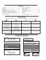
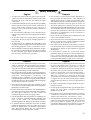
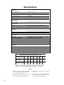
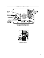
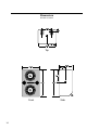
Operating Instructions 650-P Self-Powered Subwoofer Patents Pending Copyright © 1997, Meyer Sound Laboratories, Inc. All rights reserved Part #: 05.036.007.01 Rev B Contents Introduction ......................................................... 3 AC Power ............................................................ 3 Audio Input .......................................................... 5 Amplification and Protection Circuitry .................. 5 Configuration, Placement, and Polarity ...............7 Measurement and System Integration Tools ......8 Full-Range Systems ..........................................8 Driver Troubleshooting .....................................10 Safety Summary ..............................................11 Specifications ...................................................12 Controls and Connectors ................................... 13 Dimensions ........................................................ 14 Notes ...............................................................15 Contact Information ..........................................16 Symbols Used These symbols indicate important safety or operating features in this booklet and on the chassis. ! Dangerous voltages: risk of electric shock Important operating instructions Frame or chassis Protective earth ground Pour indiquer les risques résultant de tensions dangereuses Pour indequer important instructions Masse, châssis Terre de protection Zu die gefahren von gefährliche spanning zeigen Zu wichtige betriebsanweisung und unterhaltsanweisung zeigen Rahmen oder chassis Die schutzerde Para indicar importante funcionar y mantenimiento instrucciones Armadura o chassis Tierra proteccionista Para indicar azares provengo de peligroso voltajes Declaration of Conformity According to ISO/IEC Guide and EN 45014 The Manufacturer: declares that the product: Name: Meyer Sound Laboratories Address: 2832 San Pablo Avenue Berkeley, California 94702-2204, USA conforms to the following Product Specifications: Safety: EMC: EN 60065: 1994 EN 55022: 1987 IEC 801-2: 1984 IEC 801-3: 1984 IEC 801-4: 1984 - Class A 8 kV 3 V/m 0.5 kV Signal Lines, 1.0kV Power Lines The product herewith complies with the requirements of the Low Voltage Directive 73/23/EEC and the EMC Directive 89/336/EEC. Office of Quality Manager Berkeley, California USA October 1, 1995 2 Product Name: Product Options: 650-P All Environmental Specifications for Meyer Sound Electronics Products Operating temperature: 0°C to +45°C Nonoperating temp: < 40°C or > +75°C Humidity: to 95% at 35°C Operating altitude: to 4600 m (15,000 ft) Nonoperating altitude: Shock: to 6300 m (25,000 ft) 30 g 11 msec half-sine on each of 6 sides 10 55Hz (0.010 m peak-to-peak excursion) Vibration: U ® L UL LISTED 3K59 C ® COMMERCIAL AUDIO SYSTEM Voltage Requirements Introduction The 650-P, Meyer Sound’s most powerful self-powered subwoofer, contains independent amplifier and control electronics for two 18” drivers in a compact enclosure. This integrated design improves performance, durability, and reliability, eliminates amplifier racks, and simplifies setup and installation. The 650-P has the following acoustical specifications: Frequency Response ±4 dB 28 100 Hz Phase Response ±30° 45 145 Hz Dynamic Range > 110 dB See page 14 for complete specifications. The 650-P is compatible with the Meyer MSL-4, CQ™ Series, and MTS-4 self-powered speakers and can be used in any system requiring additional low frequency reinforcement.. The 650-P operates safely and without audio discontinuity if the AC voltage stays within the ranges 85– 134V or 165–264V, at 50 or 60Hz. Immediately after applying AC power, the green Active LED on the user panel illuminates and the proper operating voltage is automatically selected, but the system is muted. During the next three seconds, the primary fan turns on, the main power supply slowly ramps on, and the system is enabled to pass audio signals. TROUBLESHOOTING NOTE: If the Active LED does not illuminate or the system does not respond to audio input after ten seconds, remove AC power to avoid possible damage to the unit. Experienced electronics technicians with access to a test bench can verify proper operation for the power supply and amplifier system with The Meyer Sound Self-Powered Series MP-2 and MP-4 Field Verification Procedure (part # 17.022.066.01; contact Meyer Sound to receive this document). All other users should contact Meyer Sound or an authorized Meyer service center. The 650-P can be equipped to operate with the Remote Monitoring System (RMS™) interface network and software application. RMS displays signal and power levels, driver and cooling fan status, limiter activity, and amplifier temperature for all speakers in the network on a Windows-based PC. Contact Meyer Sound for more information about RMS. If the voltage decreases below the lower bound of either operating range (known as a brown-out period), the supply uses current from its storage circuits and continues to function briefly. The unit turns off if the voltage does not increase above the threshold before the storage circuits are depleted. The length of time that the 650-P continues to operate during brown-out depends on how low the voltage drops and the audio source level during this period. AC Power If the voltage fluctuates within either operating range, automatic tap selection stabilizes the internal operating voltage. This tap selection is instantaneous and there are no audible artifacts. If the voltage increases above the upper bound of either range, the power supply turns off rapidly, preventing damage to the unit. When AC power is applied to the 650-P, the Intelligent AC™ supply automatically selects the correct operating voltage, allowing the 650-P to be used in the US, Europe, or Japan without manually setting a voltage switch. The Intelligent AC power supply also protects the 650P by performing surge suppression for high voltage transients (up to 275V), minimizing inrush current, and filtering EMI. The 650-P uses a NEMA L6-20P or IEC 309 male power inlet and satisfies UL, CSA, and EC safety standards. If the 650-P shuts down due to either low or high voltage, the power supply automatically turns on after three seconds if the voltage has returned to either normal operating range. If the 650-P does not turn back on after ten seconds, remove AC power and refer to the TROUBLESHOOTING NOTE above. Continuous voltages above 275VAC may damage the unit! 3 Current Requirements Safety Issues The 650-P presents a dynamic load to the AC mains which causes the amount of current to fluctuate between quiet and loud operating levels. Since different types of cables and circuit breakers heat up (and trip) at varying rates, it is essential to understand the types of current ratings and how they correspond to circuit breaker and cable specifications. Pay close attention to these important electrical and safety issues. The maximum continuous RMS current is the maximum RMS current over a duration of at least 10 seconds. It is used to calculate the temperature increase in cables, which is used to select cables that conform to electrical code standards. It is also used to select the rating for slow-reacting thermal breakers. The maximum burst RMS current is the maximum RMS current over a one second duration. It is used to select the rating for most magnetic breakers. The maximum instantaneous peak current during burst is used to select the rating for fast-reacting magnetic breakers and to calculate the peak voltage drop in long AC cables according to the formula Use a power cord adapter to drive the 650-P from a standard 3-prong outlet (NEMA 5-15R; 125V max). earth ground chassis ground The 650-P requires a grounded outlet. Always use a grounding adapter when connecting to ungrounded outlets. V pkdrop = I pk x R total cable Use the table below as a guide to select cables and circuit breakers with appropriate ratings for your operating voltage. Do not use a ground-lifting adapter or cut the AC cable ground pin. 650-P Current Ratings Max. Continuous RMS 115 V 230 V 100 V 8 ARMS 4 ARMS 10 ARMS Max. Burst RMS 15 ARMS 8 ARMS 18 ARMS Max. Peak During Burst 22 APEAK 11 APEAK 25 APEAK The minimum electrical service amperage required by a system of Meyer speakers is the sum of their maximum continuous RMS currents. We recommend allowing an additional 30% above the minimum amperage to prevent peak voltage drops at the service entry. TROUBLESHOOTING NOTE: In the unlikely case that the circuit breakers trip (the white center buttons pop out), do not reset the breakers! Contact Meyer Sound for repair information. 4 Keep all liquids away from the 650-P to avoid hazards from electrical shock. Do not operate the unit if the power cables are frayed or broken. Tie-wrap anchors on the amplifier chassis provide strain relief for the power and signal cables. Insert the plastic tie-wraps through the anchors and wrap them around the cables. The cabinet, exposed electronic circuitry, and drivers can receive protective treatment that permits safe use in wet conditions. Additionally, a rain hood can be fitted to shield cables and electronics. Do not install a unit outdoors without weather protection! Contact Meyer Sound for more information. Power Connector Wiring Conventions Use the following AC cable wiring diagram to create international or special-purpose power connectors: brown = hot blue = neutral yellow/green = earth ground (chassis) AC cable color code If the colors referred to in the diagram don't correspond to the terminals in your plug, use the following guidelines: • Connect the blue wire to the terminal marked with an N or colored black. • Connect the brown wire to the terminal marked with an L or colored red. • Connect the green and yellow wire to the terminal marked with an E (or ) or colored green (or green and yellow). Audio Input The 650-P presents a 10 kOhmbalanced input impedance to a three-pin XLR connector wired with the following convention: Pin 1 — 220 kOhm to chassis and earth ground (ESD clamped) Pin 2 — Signal Pin 3 — Signal Case — Earth (AC) ground and chassis Differential Inputs Shorting an input connector pin to the case can form a ground loop and cause hum. Pins 2 and 3 carry the input as a differential signal; their polarity can be reversed with the input polarity switch on the user panel. If the switch is in the up position, pin 2 is hot relative to pin 3, resulting in a positive pressure wave when a positive signal is applied to pin 2. Use standard audio cables with XLR connectors for balanced signal sources. TROUBLESHOOTING NOTE: If abnormal noise (hum, hiss, popping) is produced from the loudspeaker, disconnect the audio source from the speaker. If the noise stops, then the problem is not within the loudspeaker; check the audio input and AC power. A single source can drive multiple 650-Ps with a paralleled input loop, creating an unbuffered hardwired loop connection. Make certain that the source equipment can drive the total load impedance presented by the paralleled input circuit. For example, since the input impedance of a single 650-P is 10 kOhms, cascading 20 650-Ps produces a balanced input impedance of 500 Ohms. If a 150 Ohm source is used, the 500 Ohm load results in a 2.28 dB loss. Amplification and Protection Circuitry Each driver in the 650-P is powered by one channel of the Meyer MP-2, a 1240 W amplifier (620 W/ch) utilizing complementary power MOSFET output stages (class AB/H). The following sections discuss the MP-2’s limiting circuitry and the two-fan cooling system. TruPower™ Limiting System Conventional limiters assume that the resistance of a speaker remains constant and set the limiting threshold by measuring voltage only. This method is inaccurate because the speaker’s resistance changes in response to the frequency content of the source material and thermal variations in the speaker’s voice coil and magnet. Conventional limiters begin limiting prematurely, which under-utilizes system headroom and deprives the speaker of its full dynamic range. The TruPower limiting (TPL) system accounts for varying speaker impedance by measuring current, in addition to voltage, to compute the power dissipation and voice coil temperature. TPL improves performance before and during limiting by allowing the speaker to produce its maximum SPL across its entire frequency range. TPL also extends the lifetime of the drivers by controlling the temperature of the voice coil. 5 When the safe continuous power level is exceeded, a single limiter engages, affecting both amplifier channels equally. TPL activity is indicated by the Sub Limit LED on the user panel. The limiter ceases operation when the power level returns to normal and does not affect the signal when the LED is inactive. The 650-P performs within its acoustical specifications and operates at a normal temperature if the TPL LED is on for no longer than two seconds, and off for at least one second. If the LED remains on for longer than three seconds, the 650-P is hard limiting with these negative consequences: • Increasing the input level will not increase the volume. • The system distorts due to clipping and nonlinear driver operation. • The life-span of driver and amplifier components is reduced because they are subjected to excessive heat. Fans and Cooling System The 650-P uses a forced-air cooling system with two fans to prevent the amplifiers from overheating. The fans draw air in through ducts on the front of the cabinet, over the heatsinks, and out the rear of the cabinet. Since dust does not accumulate in the amplifier circuitry, its life-span is increased significantly. A foam insert filter, in combination with the entire front grill surface, acts as an air filter for the cooling system. Despite the filtering, extensive use or a dusty operating environment can allow dust to accumulate along the path of the airflow, preventing normal cooling. We recommend periodically removing the grill, filter, and amplifier module and using compressed air to clear dust from the grill, filter, fans, and heatsinks. Make sure that the air ducts are clear and that there is at least six inches clearance for exhaust behind the cabinet. cooling fans The TPL LED can indicate an imbalance in a system of speakers by functioning like a spectrum analyzer. If speakers in a subwoofer, mid-bass, or mid-hi subsystem begin to limit before reaching the required operating level for the entire system, then that subsystem needs to be supplemented with additional speakers. NOTE: Although the TPL limiters exhibit smooth sonic characteristics, we do not recommend using them for intentional compression effects. Use an outboard compressor/limiter to compress a mixed signal. Driver Excursion Clamp The drivers in the 650-P are protected from over-excursion by an excursion clamping circuit that does not have attack or release time constants. The circuit provides instantaneous braking for the drivers without the pumping effects commonly produced by compressor/ limiters. The circuit uses sophisticated filters to minimize the distortion normally caused by clamping and clipping. As the 650-P’s input signal is increased past the clamping point, the output signal remains at a fixed level, protecting the drivers and minimizing negative sonic effects. The 650-P operates safely if the Exc. Clamp LED is on for no longer than two seconds, and off for at least one second. air intake power supply heatsinks air filter A variable-speed primary fan runs continuously with an inaudible operating noise of 22 dBA at 1 m at its slowest speed. The speed of the primary fan begins increasing when the temperature of the heatsinks reaches 42°C. The fan reaches full speed at 62°C and is barely audible near the cabinet, even without an audio signal. In the unusual event that the heatsink temperature reaches 74°C, the secondary fan turns on; it turns off when the temperature decreases to 68°C. The secondary fan is audible at close proximity without an audio signal and turns on in response to • primary fan failure (check its status immediately); • a prolonged period of high source levels in hot temperatures or direct sunlight; • accumulation of dust in the cooling system path; • driver failure. TROUBLESHOOTING NOTE: In the highly unlikely event that the secondary fan does not keep the temperature below 85°C, the 650-P automatically shuts down until AC power is removed and reapplied. If the 650-P shuts down again after cooling and reapplying AC power, contact Meyer Sound for repair information. 6 Configuration, Placement, and Polarity Designing a full-range system requires an understanding of how subwoofers respond when grouped together, how they interact with nearby walls and floors, and how their location in a system affects the choice of polarity to use for other speakers. These topics are introduced as background for the section Full-Range Systems. Configuration A single subwoofer has an essentially omnidirectional coverage pattern. A horizontal line with two adjacent subs narrows the horizontal coverage area, without changing the vertical coverage, compared to one sub. A vertical stack of two subs narrows the vertical coverage without changing the horizontal coverage. In both cases, there is 3 to 6 dB SPL of on-axis addition. Increasing the size of the horizontal or vertical array from two to three subs further narrows the respective H or V coverage without changing the corresponding V or H coverage. Both the vertical and horizontal three-sub arrays provide approximately 10 dB SPL addition more than one sub. Increasing the number of subs in the horizontal or vertical array increases the corresponding H or V directional control and the system SPL. A properly designed vertical array steers low frequencies to include balconies and upper tiers but avoids unnecessary interaction with the ceiling; a horizontal array focuses low frequencies for the longer throw distances required by large venues. Placement One of the most important factors governing subwoofer response is their placement relative to adjacent surfaces. Subwoofers gain significant power by coupling, or loading, with nearby floors and walls. Half-space loading describes a speaker coupling with one surface. Subs placed on the floor benefit from half-space loading, while flown subs in free-space (without a nearby wall or ceiling) do not. In general, subs in half-space generate twice the SPL (+6 dB) compared to the same number in free-space. It can be beneficial to fly subwoofers, despite the lack of half-space loading. Placing subwoofers within a flown cluster of mid-hi speakers creates a smooth frequency image because the subs are not separated by the distance from the cluster to the floor. NOTE: SPL values refer to an on-axis measurement position. The actual SPL addition and narrowing of coverage varies with frequency and depends on the physical displacement between cabinets, loading conditions, and room acoustics. Polarity The cabinets in the next section, Full-Range Systems, are in a close-proximity coplanar orientation, unless otherwise stated. Separating a mid-hi speaker from a subwoofer by more than 5 ft may require setting the speakers to opposite polarities to compensate for the propagation delay from each speaker to the designated listening or measurement position. In a coplanar orientation, externally amplified Meyer subwoofers require the opposite polarity setting to all Meyer self-powered speakers. The three-by-two array (below left) narrows the H and V coverages, and produces 10 to 15 dB SPL more than a single sub. Combining the vertical and horizontal arrays in an L-configuration (below right) provides more on-axis SPL and directional control than the three-bytwo array. Both the three-by-two group and L-configuration increase the SPL and directional control. 7 Measurement and System Integration Tools Full-Range Systems Meyer Speaker Types It is essential that even the most carefully assembled sound systems be analyzed with precise measurement tools. We recommend using the Meyer SIM® System II Sound Analyzer and CP-10 Parametric Equalizer to • assist the process of choosing and configuring speakers; • measure propagation delays between subsystems to set the correct polarity and delay times; • measure and equalize variations in frequency response caused by the acoustical environment and the placement and interaction of speakers. Contact Meyer Sound for assistance with your application. We recommend using the Meyer LD-1A Line Driver to integrate different types of Meyer self-powered speakers into a complete system. The LD-1A has two channels equipped to control a full-range main system, and six auxiliary channels for down-fill, front-fill, and delay systems. The LD-1A maintains signal integrity for long cable paths and provides the following useful functions: • The Lo Cut switch activates a high-pass filter (160 Hz, –12 dB/oct, Q = 0.8) that performs a crossover function for the Mid-Hi output. • The DS-2 & Sub Crossover switch (channels 1 and 2 only) activates a crossover network optimized for the DS-2P when used with the 650-P. With the switch in, frequencies below 80 Hz are sent to the Sub output (for the 650-P), and above 80 Hz to the DS-2 output. When the 650-P is used without the DS-2P, the switch should be out, which sends a full-range signal to both the DS-2 and Sub outputs. • The DS-2 f and Sub f switches (channels 1 and 2 only) toggle the polarity for the DS-2 and Sub outputs. • The Mid-Hi, DS-2, and Sub outputs (channels 1 and 2 only) each have their own gain control and mute switch. POLARITY NOTE: The polarity for Meyer self-powered speakers may be reversed using the input polarity switch on the user panel. The LD-1A also allows polarity reversal with the DS-2 f and Sub f switches for speakers connected to the DS-2 and Sub outputs. When making polarity decisions in applications that include the LD-1A, check the state of all polarity switches. 8 The following Meyer speakers are mentioned in the example applications. MSL-4 CQ Series MTS-4 PSW-2 650-R2 Self-powered mid-hi speaker Self-powered mid-hi speaker Self-powered full-range speaker Self-powered subwoofer Externally amplified subwoofer The Meyer self-powered speakers listed above have a loop connection to send the input signal to another speaker. Full-range signals may be applied to all Meyer self-powered subwoofers because they have built-in active crossovers that filter mid-hi frequencies. 650-P and MSL-4 The 650-P is compatible with the MSL-4, CQ, and MTS-4. However, since the low frequency response for each speaker overlaps with the 650-P, the system frequency response exhibits a rise in the range 65 – 100 Hz (MSL4), 40 – 100 Hz (CQ), and 30 – 100 Hz (MTS-4). It is important to emphasize that the speakers are in phase in this region. The rise can be corrected using the Meyer CP-10 Parametric Equalizer, if desired. MSL-4 CP-10 EQ (1 Channel) input loop input 650-P Set the MSL-4 and 650-P to the same polarity. LD-1A with 650-P and MSL-4 LD-1A with MSL-4, DS-2P, and 650-P Using the LD-1A’s Lo Cut filter for the CH 1 Mid-Hi output also eliminates the low frequency rise caused by the frequency response overlap between the MSL-4 and 650-P. Although a typical MSL-4:650-P ratio is 2:1, CH 1’s Sub and Mid-Hi level controls allow this ratio to vary while maintaining control of the spectral balance of the system. The DS-2 & Sub Crossover switch should be out. Adding the DS-2P to an MSL-4/650-P system enhances LF power and clarity. With the DS-2 & Sub Crossover switch in, the DS-2P and 650-P each receive signals optimized for their frequency response capabilities. CH 1 Mid-Hi CH1 Input The MSL-4 is driven from the CH 1 Mid-Hi output with the Lo Cut filter in to minimize the overlap in frequency response with the DS-2P and 650-P. Set the 650-P to the opposite polarity to the MSL-4 and DS-2P. MSL-4 LD-1A Line Driver CH 1 Sub 650-P Set the MSL-4 and 650-P to the same polarity. LD-1A with Flown PSW-2 and MSL-4; 650-P on the Floor Including subwoofers in a flown cluster provides a smooth frequency image because the low and mid-hi frequencies are produced from speakers located close together. The identical dimensions of the PSW-2 and MSL-4 allow them to be easily flown together. The CH 1 Mid-Hi output drives the MSL-4 with the Lo Cut filter in. The CH 1 Sub and DS-2 outputs drive the 650-Ps and PSW-2s with the DS-2 & Sub Crossover switch out, which sends a full-range signal with independent level control to each speaker. Set the 650-P to the opposite polarity to the DS-2P and MSL-4. 650-P and 650-R2 Although it is preferable to employ the 650-P in a completely self-powered system, the 650-P can be used with the 650-R2 externally amplified subwoofer if: • the B-2EX CEU is set to the maximum output level; • the 650-R2’s amplifier is set to 26 dB gain; • the 650-R2’s amplifier is set to the opposite polarity of the 650-P. POLARITY NOTE: It is advisable to check the polarity of adjacent 650-P and 650-R2 cabinets by following the instructions in the Verifying Driver Polarity section on page 10. Set the MSL-4 and PSW-2 to the same polarity. The polarity for the 650-P depends on the height and distance of the measurement position from the subwoofers and flown cluster. 9 Driver Troubleshooting Troubleshooting with TPL The TPL LED can indicate serious driver problems, if interpreted correctly. If one 650-P in a system exhibits substantially more TPL activity than others receiving the same audio signal, then one or both drivers in that unit may have a short circuit. This is a potentially dangerous condition for the electronics; shut the 650-P down immediately. Driver Polarity in the Same Loudspeaker Use the following test procedure to verify polarity between drivers in the same loudspeaker: 1. Place a monitoring microphone 3 ft from the front of the loudspeaker at the midway point between the two drivers. 2. Connect a signal source to the loudspeaker and note the frequency response. The TPL circuit does not activate if there is no power dissipation in the driver, regardless of the input signal level. Therefore, if all 650-Ps in a system receiving the same audio signal exhibit TPL activity except one, then that unit may have an open voice coil; disconnect it and contact Meyer Sound for repair information. NOTE: The Remote Monitoring System (RMS) provides precise information about peak power, peak voltage, and average voltage (VU) for each amplifier channel, enabling a more complete driver diagnostic than the TPL LEDs. Contact Meyer Sound for more information about RMS. Driver Replacement To determine whether a driver is functioning properly, or replace a damaged driver, contact Meyer Sound to obtain the Low Driver Inspection and Evaluation Procedure for Self-Powered Series Products (part # 17.010.120.01). Verifying Driver Polarity Incorrect driver polarity impairs system performance and may damage the drivers. All Meyer loudspeakers are shipped with the drivers in correct alignment. However, if the driver or circuit wiring has been removed or disassembled in any loudspeaker in a system for any reason, it is essential to check the polarity between drivers in the same cabinet and between adjacent loudspeakers. NOTE: Since polarity reversal causes excessive driver excursion at high source levels, use moderate levels for these tests. 10 The polarity is correct if the frequency response is ±4 dB 28 – 100 Hz. Cancellation greater than 6 dB in the same range indicates polarity reversal. Polarity Between Adjacent Loudspeakers Use the following test procedure to verify the polarity between adjacent loudspeakers of the same type: 1. Position two loudspeakers adjacent to each other. 2. Place a measurement microphone 3 ft from the speakers on the axis between them. 3. Connect a signal source to one speaker and note the frequency response and overall level. 4. Apply the same signal to the second speaker with the first speaker still connected. The polarity is correct if the frequency response remains constant with a significant increase in amplitude. Broadband cancellation (decreased overall level) indicates polarity reversal. NOTE: Do not attempt to check more than two adjacent speakers in one test. Detecting polarity reversal among more than two speakers is difficult and may damage the drivers in the cabinet with reversed polarity. Safety Summary English Français • To reduce the risk of electric shock, disconnect the loudspeaker from the AC mains before installing audio cable. Reconnect the power cord only after making all signal connections. • Pour réduire le risque d’électrocution, débrancher la prise principale de l’haut-parleur, avant d’installer le câble d’interface allant à l’audio. Ne rebrancher le bloc d’alimentation qu’après avoir effectué toutes les connections. • Connect the loudspeaker to a two-pole, three wire grounding mains receptacle. The receptacle must be connected to a fuse or circuit breaker. Connection to any other type of receptacle poses a shock hazard and may violate local electrical codes. • Branchez l’haut-parleur dans une prise de courant à 3 dérivations (deux pôles et la terre). Cette prise doit être munie d’une protection adéquate (fusible ou coupe-circuit). Le branchement dans tout autre genre de prise pourrait entraîner un risque d’électrocution et peut constituer une infraction à la réglementation locale concernant les installations électriques. • Do not install the loudspeaker in wet or humid locations without using weather protection equipment from Meyer Sound. • Do not allow water or any foreign object to get inside the loudspeaker. Do not put objects containing liquid on, or near, the unit. • To reduce the risk of overheating the loudspeaker, avoid exposing it to direct sunlight. Do not install the unit near heat emitting appliances, such as a room heater or stove. • This loudspeaker contains potentially hazardous voltages. Do not attempt to disassemble the unit. The unit contains no user serviceable parts. Repairs should be performed only by factory trained service personnel. Deutsch • Ne pas installer l’haut-parleur dans un endroit où il y a de l’eau ou une humidité excessive. • Ne pas laisser de l’eau ou tout objet pénétrer dans l’hautparleur. Ne pas placer de r´cipients contenant un liquide sur cet appareil, ni à proximité de celui-ci. • Pour éviter une surchauffe de l’haut-parleur, conserverla à l’abri du soleil. Ne pas installer à proximité d’appareils dégageant de la chaleur tels que radiateurs ou appareils de chauffage. • Ce haut-parleur contient des circuits haute tension présentant un danger. Ne jamais essayer de le démonter. Il n’y a aucun composant qui puisse être réparé par l’utilisateur. Toutes les réparations doivent être effectuées par du personnel qualifié et agréé par le constructeur. Español • Um die Gefahr eines elektrischen Schlages auf ein Minimum zu reduzieren, den Lautsprecher vom Stromnetz trennen, bevor ggf. ein Audio-Schnittstellensignalkabel angeschlossen wird. Das Netzkabel erst nach Herstellung aller Signalverbindungen wieder einstecken. • Para reducir el riesgo de descarga eléctrica, desconecte de la red el altoparlante antes de instalar el cable de señalización de interfaz de la segnale. Vuelva a conectar el conductor flexible de alimentación solamente una vez efectuadas todas las interconexiones de señalizatción. • Der Lautsprecher an eine geerdete zweipolige DreiphasenNetzsteckdose anschließen. Die Steckdose muß mit einem geeigneten Abzweigschutz (Sicherung oder Leistungsschalter) verbunden sein. Der Anschluß der unterbrechungsfreien Stromversorgung an einen anderen Steckdosentyp kann zu Stromschlägen führen und gegen die örtlichen Vorschriften verstoßen. • Conecte el altoparlante a un tomacorriente bipolar y trifilar con neutro de puesta a tierra. El tomacorriente debe estar conectado a la protección de derivación apropiada (ya sea un fusible o un disyuntor). La conexión a cualquier otro tipo de tomacorriente puede constituir peligro de descarga eléctrica y violar los códigos eléctricos locales. • Der Lautsprecher nicht an einem Ort aufstellen, an dem sie mit Wasser oder übermäßig hoher Luftfeuchtigkeit in Berührung kommen könnte. • No instale el altoparlante en lugares donde haya agua o humedad excesiva. • Darauf achten, daß weder Wasser noch Fremdkörper in das Innere den Lautsprecher eindringen. Keine Objekte, die Flüssigkeit enthalten, auf oder neben die unterbrechungsfreie Stromversorgung stellen. • Um ein Überhitzen dem Lautsprecher zu verhindern, das Gerät vor direkter Sonneneinstrahlung fernhalten und nicht in der Nähe von wärmeabstrahlenden Haushaltsgeräten (z.B. Heizgerät oder Herd) aufstellen. • Im Inneren diesem Lautsprecher herrschen potentiell gefährliche Spannungen. Nicht versuchen, das Gerät zu öffnen. Es enthält keine vom Benutzer reparierbaren Teile. Reparaturen dürfen nur von ausgebildetem Kundenienstpersonal durchgeführt werden. • No deje que en el altoparlante entre agua ni ningún objeto extraño. No ponga objetos con líquidos encima de la unidad ni cerca de ella. • Para reducir el riesgo de sobrecalentamiento, no exponga la unidad a los rayos directos del sol ni la instale cerca de artefactos que emiten calor, como estufas o cocinas. • Este altoparlante contiene niveles de voltaje peligrosos en potencia. No intente desarmar la unidad, pues no contiene piezas que puedan ser repardas por el usuario. Las reparaciones deben efectuarse únicamente por parte del personal de mantenimiento capacitado en la fábrica. 11 Specifications Acoustical 1 Frequency Response Phase Response Maximum SPL Music as source Pink noise as source Dynamic Range2 ±4 dB 28 100Hz ±30° 45 145Hz 136 dB peak 120 dB continuous; 130 dB peak > 110 dB Transducers Sub Frequency Two 18" diameter MS-18 cone drivers Audio Input Type Connector Nominal Input Level 10kOhm impedance, electronically balanced XLR (A-3) male and female +4 dBu (1.23Vrms) Amplifiers Type Burst Capability3 THD, IM, TIM Complementary power MOSFET output stages class AB/H 1240 Watts (620 Watts per channel) < .02 % AC Power Connector Automatic voltage selection4 Max Continuous RMS Current (> 10s) Max Burst RMS Current (< 1s) Max Peak Current During Burst Soft-Current Turn-on 250V NEMA L6-20P / IEC 309 Twistlock male receptacle 85 134V / 165 264V; 50Hz / 60Hz 115V: 8A 230V: 4A 100V: 10A 115V: 15A 230V: 8A 100V: 18A 115V: 22Apk 230V: 11Apk 100V: 25Apk Inrush current < 12A @115V Physical Dimensions Weight Enclosure Finish Protective Grill 30" W x 45" H x 22.5" D 221 lb (100 kg); shipping: 250 lb (113 kg) All birch plywood Black textured Perforated metal grill, fiberglass screen 650-P Maximum Peak and Continuous SPL Frequency (Hz) 32 42 50 63 80 100 125 Peak (dB) 126 130 132 134 133 132 124 Continuous (dB) 114 120 127 126 124 122 120 Maximum on-axis SPL measured at 1 m using a sinewave signal source, 1/3 octave intervals, half-space loading, < 10% THD. Notes 1. Subject to half-space loading; measured with one-third octave frequency resolution in fixed ISO bands at 1 m. 2. Measured as the ratio between the peak SPL and the A-weighted noise floor. 12 3. Nominal 8 ý resistive load, pink noise, 100V peak. 4. The unit is rated at 88125V and 182 235V, 50/60Hz, to satisfy EC standards for 10% to 6% AC line voltage. Controls and Connectors Rear User Panel shown with the optional Remote Monitoring System (RMS) panel European User Panel with IEC 309 connector 13 Dimensions All units in inches Top Front 14 Side Notes 15 Contact Information Meyer Sound Laboratories, Inc. 2832 San Pablo Avenue Berkeley, California 94702 Telephone: 510 - 486 - 1166 FAX: 510 - 486 - 8356 E-mail: [email protected] http://www.meyersound.com 16 Meyer Sound Germany GmbH Carl Zeiss Strasse 13 56751 Polch, Germany Telephone: 49.2654.9600.58 FAX: 49.2654.9600.59 E-mail: [email protected]