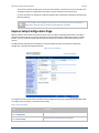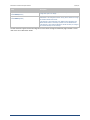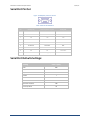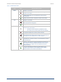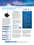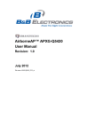
1
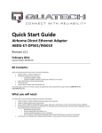
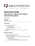
Quick Start Guide AirborneDirect™ Industrial Serial Device Server ABDG-SE-DP501 Revision v1.1 February 2011 Document Number: 100-8107-110 Kit Contents: Upon receiving the kit please check that you received the following: ABDG-SE-DP501 Unit 2dBi, 2.4Ghz 50 ohm, omni-directional antenna Quick Start Guide 5 VDC power supply (optional, included only if ordered as an accessory) If any of the above contents are missing or appear damaged please contact Quatech Sales support directly at (800) 553-1170 or [email protected]. What you will need: To evaluate the unit you will need the following components and facilities: ABDG-ET-DP501 unit with included antenna attached. Laptop or desktop system with an Serial port or a serial adapter. AC power outlet for optional ABDG-SE-DP501 power supply. 802.11b/g network for testing the unit, either AdHoc or Infrastructure (Access Points) mode. The test network configuration must be known. Required information will include: o SSID (Wireless network name). o Security settings (WEP, WPA, WPA2, etc.). o Security credentials (passphrase, key or certificates). o Static IP address, Subnet Mask and Gateway address if static IP addresses are used on the test network. A web browser on the laptop top or desktop (MS Explorer, Firefox, Opera and Chrome v4.0 are supported). Serial cable to connect Airborne™ device to host system. AirborneDirect™ Serial Device Server Quick Start Guide Quatech, Inc. Getting Started: 1. Configuring Device – Enterprise Serial (ABDG-SE-DP5XX) The ABDG-SE-DP5XX family does not have an Ethernet port for initial configuration so initial configuration can be performed through the serial port. To do this it is necessary to connect using the serial connector. 2. Connect a Host Computer Connect the serial pigtail connector to the serial port on a host computer. 3. It may be necessary to use a gender changed that includes a Null Modem adapter. Interacting with the AirborneDirect™ device On the Host computer, use a terminal emulation program to interact with the device issuing Quatech Command Line Interface (CLI) commands. CLI commands let you request status or change parameter settings. Press the Enter key (<CR>) after each command line you type. After the module starts, type the following CLI command to log in (you must log in before CLI commands can be recognized): Table - UART Authentication CLI Command Description Send Break Sequence The serial port starts up in a listen mode waiting for a request for a data tunnel. To access the CLI mode in which set-up can take place the break sequence must be sent. The default break sequence for the device is ÿ~ABD The sequence must be sent with no trailing characters. If received correctly the device will respond OK. auth dpac dpac <CR> 100-8107-110 The module responds with OK, indicating that it executed the command successfully. (If you did not receive OK, check the settings in your terminal emulation program). You will have to break into CLI mode and log into the module after any reset or restart. 2 February 2011 AirborneDirect™ Serial Device Server Quick Start Guide 4. Quatech, Inc. Determine and Store the Access Point SSID On the Host computer, use the terminal emulation program to type the following CLI commands in the order shown: Table - UART SSID & Authentication CLI Command Description wl-scan<CR> The module scans for APs and returns information on each one it discovers. Note the SSID value that is returned, as you will need to enter it when configuring the device in the next steps. wl-ssid [SSID]<CR> Associates the module with the network name [SSID] you specify. [SSID] is the value returned by the wl-scan command. commit<CR> Stores the information to flash memory. restart Restarts the device and installs the new settings. If your access point has security enabled, you will also need to use the CLI to enter those parameters (See the Enterprise CLI Reference Guide for details). That setup is outside the scope of this user guide, which assumes that the AP being tested with has no security. After issuing the commands, the unit will restart and apply the network settings. Once restarted the LINK LED will stop blinking and go solid. If DHCP is enabled on the network the POWER and LINK LED’s will turn solid green. 5. Determine the Device’s IP address On the Host computer, use the terminal emulation program to type the following CLI commands: Table - UART Determine Module's IP Address CLI Command Description Send Break Sequence The serial port starts up in a listen mode waiting for a request for a data tunnel. To access the CLI mode in which set-up can take place the break sequence must be sent. The default break sequence for the device is ÿ~ABD The sequence must be sent with no trailing characters. If received correctly the device will respond OK. 6. auth dpac dpac <CR> Authenticate with the device server. wl-ip<CR> The module returns the IP address assigned to it by the DHCP server. Accessing the Device Using the Web Interface Open a browser; in the URL field enter the IP address observed when the wl-ip CLI commend was issued in step #5. When prompted to enter username dpac and password dpac. Go to the section titled Express Setup Configuration Page. 7. Accessing the Device Using Telnet On the Remote computer, use a terminal emulation program to start a Telnet session. To connect to the device use TCP/IP. Enter the IP address obtained in step#5 and connect on port 23. 100-8107-110 3 February 2011 AirborneDirect™ Serial Device Server Quick Start Guide Quatech, Inc. The terminal emulator will attempt to connect to the IP address; if successful you will now be able to use the WLAN interface for configuration of the device using the Command Line Interface (CLI). For more information on the full CLI command set please refer to the Airborne Enterprise Command Line Reference Manual. Any of the available Terminal Emulation programs may be used. Please follow the specific applications requirements to make the TCP/IP connection and authenticate with the module. Express Setup Configuration Page When the devices web interface is accessed for the first time an Express Setup page will be shown. This page is designed to allow a quick device set-up by presenting the most popular device configuration options in a single location. For more advanced configurations the full set of options are available in the feature links (left-hand column). The Express Setup web page will only display the necessary fields based upon the selections made during configuration. The Express Setup page looks like: Figure - Express Setup Page To configure the device for operation each field must be configured correctly. The following steps should be taken to configure the device (Note: not all fields will be visible): Table - Express Page Setup Step Description Navigation Bar You will see a group of fields under the banner of WLAN Parameters. Select Configuration Feature Link Select Express Setup 100-8107-110 This step is optional. If this is the first time the device has been configured this page will automatically be displayed. 4 February 2011 AirborneDirect™ Serial Device Server Quick Start Guide Quatech, Inc. Step Description Select Discovery OEM Device Name This parameter allows you to name the device uniquely or group into a functional set. When device discovery is used this name identifies the found device. If you wanted to uniquely identify the device you could mark it with a label e.g. Dev1, and then enter Dev1 in this field. When the device is found it will identify itself as Dev1. Alternately you could indicate the type of equipment the device is attached to e.g. Haas TL-2 (CNC Turning Center), by giving the unit a name like Haas_TL_2. When discovered you can then identify the device you are accessing. Enter the text string is you wish to change the default value. This field is optional. Select Radio Startup Mode Select On from the drop down menu for the radio to operate. Select Wireless LAN Connection Type If you are using Access Points make sure this is set to Infrastructure from the drop down menu. If you want to use AdHoc set this accordingly. Additional settings may be required to fully configure for AdHoc mode, these are covered in the User Manual for the device. Select SSID Enter the name of the wireless network you wish to access. This field is case sensitive. Select Wireless LAN Security Type Select the security type the wireless network you wish to access is using. Depending upon the option you choose you may have to enter additional information. Once you have selected the security type the required inputs will be made accessible by un-graying the fields that must be completed. If the security type is not in the available selections, more are available in the WLAN Security Settings page. If you choose to use this page make sure you commit the changes you have already made before moving to the WLAN Security Settings page. Select WLAN DHCP If your WLAN network uses DHCP to assign IP addresses to the wireless clients, select Enabled from the drop down menu. If you are using static IP addresses select disabled from the drop down menu. WLAN Static IP and WLAN Subnet Mask will need to be entered. Select Ethernet DHCP If the Ethernet network connected to the Ethernet port uses DHCP to assign IP addresses to the wired clients, you should select Enabled from the drop down menu. If you are using static IP addresses you should select Disabled from the drop down menu. Ethernet Static IP and Ethernet Subnet Mask will need to be entered. Important: This field is only used if the Ethernet interface is set as a client (default for Serial devices). If set as a router the field is ignored. See the User’s Manual for a full description of configuring the unit as an Ethernet router. Select WLAN Static IP This field defines the static IP address for the wireless interface. This address is only used if the WLAN DHCP is disabled or DHCP failed. Default: 192.168.10.1 Select WLAN Subnet Mask This field defines the subnet mask used by the wireless interface. This mask is only used if the WLAN DHCP is disabled or DHCP failed. Default: 255.255.255.0 Select Ethernet Static IP This field defines the static IP address for the Ethernet interface. When configured as a serial device server (Ethernet interface is in client mode) this address is only used if the Ethernet DHCP is disabled or DHCP failed. Default: 192.168.2.100 Select Ethernet Subnet Mask This field defines the subnet mask used by the Ethernet interface. When configured as a serial device server (Ethernet interface is in client mode) this mask is only used if the Ethernet DHCP is disabled or DHCP failed. Default: 255.255.255.0 Press Commit [Button] Saves changes to the device. 100-8107-110 5 February 2011 AirborneDirect™ Serial Device Server Quick Start Guide Quatech, Inc. Step Description Optional Reloads the Express Settings page. Select this is you have further configuration options to change. Press Reload [Button] Optional Press Restart [Button] Restarts the device. After the device as rebooted it will attempt to authenticate to the configured network. As long as the network is in range the wireless interface will connect. If the network is using DHCP then an IP address will be assigned to the WLAN interface and IP connectivity is possible over the WLAN network. If the network is using static IP addresses it will be necessary to configure the network interface, see the next step. The web interface supports advanced configuration of the device through the additional pages available. Please refer to the User’s Manual for details. 100-8107-110 6 February 2011 AirborneDirect™ Serial Device Server Quick Start Guide Quatech, Inc. Serial Port Pin Out Figure - DE-9M (DB-9) Connector Pin-out Table– Serial Port Pin Definition Pin RS232 (DTE) RS232 w/Power on pin 9 RS422/485 1 No Connect No Connect No Connect 2 RxD RxD RxD+ 3 TxD TxD TxD+ 4 No Connect No Connect No Connect 5 GND GND GND 6 No Connect No Connect RxD- 7 RTS RTS No Connect 8 CTS CTS No Connect 9 No Connect 5VDC (Input) TxD- Serial Port Defaults Settings: Setting Port 1 (DTE) BAUD 9600 Parity None Stop Bits 8 Data Bits 1 Flow Control None Serial Default Mode Listen Input Buffer Size (Bytes) 1460 Serial Escape Mode 100-8107-110 ON 7 February 2011 AirborneDirect™ Serial Device Server Quick Start Guide Quatech, Inc. Table 1 – DP500 Indicator LED’s LED POWER Color Airborne Device State Adapter is not powered. Adapter failed Power On Self Test (POST) and is not configured for wireless communication. Adapter passed POST but is not configured for wireless network communication. Adapter passed post and is configured for wireless communication. LINK Adapter is not powered. (Periodic Blinking) Adapter is searching for a valid network (Access Point) that matches device’s configuration. Adapter has successfully associated with an Access Point. COMM If Power LED is also Off then Adapter is not powered. If Power LED is On then either: A physical connection detected on Serial/Ethernet cable. No TCP session from wireless interface has been established. No physical Serial/Ethernet connection has been detected. (Blinking – OFF/Red) A physical Serial/Ethernet connection has been detected and there is traffic across the interface. No TCP connection to the adapter has been established on the wireless interface. A TCP connection to the adapter from the wireless interface has been established but no physical connection on the Serial/Ethernet interface has been detected. (Blinking – Green/Orange) A physical Serial/Ethernet connection has been detected and there is Serial/Ethernet traffic across the interface. A TCP connection to the adapter has been established (On WLAN or Ethernet interface). A physical Serial/Ethernet connection has been detected. A TCP connection to the adapter has been established from the WLAN or Ethernet interface but no traffic has been detected. 100-8107-110 8 February 2011 5675 Hudson Industrial Parkway Hudson, OH 44236 Tel: 330.655.9000 800.553.1170 [email protected] www.quatech.com ©2010-2011 Quatech, Inc. All rights reserved.