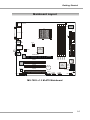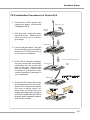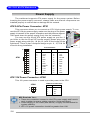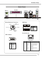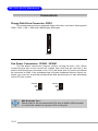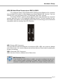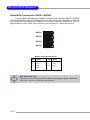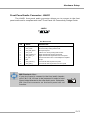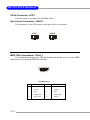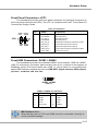
1
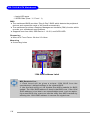
MS-7093 (v1.X)
Micro ATX Mainboard
ATI RX480 + SB400 Based
English Version
i
Manual Rev: 1.3
Release Date: Nov. 2004
FCC-B Radio Frequency Interference Statement
This equipment has been tested and found to comply with the limits for a class B
digital device, pursuant to part 15 of the FCC rules. These limits are designed to
provide reasonable protection against harmful interference when the equipment is
operated in a commercial environment. This equipment generates, uses and can
radiate radio frequency energy and, if not installed and used in accordance with the
instruction manual, may cause harmful interference to radio communications. Operation of this equipment in a residential area is likely to cause harmful interference, in
which case the user will be required to correct the interference at his own expense.
Notice 1
The changes or modifications not expressly approved by the party responsible for
compliance could void the user’s authority to operate the equipment.
Notice 2
Shielded interface cables and A.C. power cord, if any, must be used in order to
comply with the emission limits.
VOIR LA NOTICE D’INSTALLATION AVANT DE RACCORDER AU RESEAU.
Micro-Star International
MS-7093
This device complies with Part 15 of the FCC Rules. Operation is subject to the
following two conditions:
(1) this device may not cause harmful interference, and
(2) this device must accept any interference received, including interference that may
cause undesired operation.
ii
Copyright Notice
The material in this document is the intellectual property of MICRO-STAR
INTERNATIONAL. We take every care in the preparation of this document, but no
guarantee is given as to the correctness of its contents. Our products are under
continual improvement and we reserve the right to make changes without notice.
Trademarks
All trademarks are the properties of their respective owners.
Intel ® and Pentium® are registered trademarks of Intel Corporation.
PS/2 and OS ® /2 are registered trademarks of International Business Machines
Corporation.
Windows® 95/98/2000/2003/NT/XP are registered trademarks of Microsoft Corporation.
Netware ® is a registered trademark of Novell, Inc.
Award® is a registered trademark of Phoenix Technologies Ltd.
AMI® is a registered trademark of American Megatrends Inc.
Revision History
Revision
V1.3
Revision History
First release for RX480
Date
Nov. 2004
Technical Support
If a problem arises with your system and no solution can be obtained from the user’s
manual, please contact your place of purchase or local distributor. Alternatively,
please try the following help resources for further guidance.
Visit the MSI website for FAQ, technical guide, BIOS updates, driver updates,
and other information: http://www.msi.com.tw/program/service/faq/
faq/esc_faq_list.php
Contact our technical staff at: [email protected]
iii
Safety Instructions
1.
Always read the safety instructions carefully.
2.
Keep this User’s Manual for future reference.
3.
Keep this equipment away from humidity.
4.
Lay this equipment on a reliable flat surface before setting it up.
5.
The openings on the enclosure are for air convection hence protects the equipment from overheating. DO NOT COVER THE OPENINGS.
6.
Make sure the voltage of the power source and adjust properly 110/220V before connecting the equipment to the power inlet.
7.
Place the power cord such a way that people can not step on it. Do not place
anything over the power cord.
8.
Always Unplug the Power Cord before inserting any add-on card or module.
9.
All cautions and warnings on the equipment should be noted.
10. Never pour any liquid into the opening that could damage or cause electrical
shock.
11. If any of the following situations arises, get the equipment checked by a service
personnel:
h The power cord or plug is damaged.
h Liquid has penetrated into the equipment.
h The equipment has been exposed to moisture.
h The equipment has not work well or you can not get it work according to
User’s Manual.
h The equipment has dropped and damaged.
h The equipment has obvious sign of breakage.
12. DO NOT LEAVE THIS EQUIPMENT IN AN ENVIRONMENT UNCONDITIONED, STORAGE TEMPERATURE ABOVE 600 C (1400F), IT MAY DAMAGE THE EQUIPMENT.
CAUTION: Danger of explosion if battery is incorrectly replaced.
Replace only with the same or equivalent type recommended by the
manufacturer.
iv
CONTENTS
FCC-B Radio Frequency Interference Statement .......................................................... ii
Copyright Notice ............................................................................................................ iii
Trademarks .................................................................................................................... iii
Revision History ............................................................................................................ iii
Technical Support .......................................................................................................... iii
Safety Instructions ........................................................................................................ v
Chapter 1. Getting Started .................................................................................... 1-1
Mainboard Specifications ................................................................................... 1-2
Mainboard Layout ............................................................................................... 1-5
Chapter 2. Hardware Setup .................................................................................. 2-1
Central Processing Unit: CPU .............................................................................. 2-2
CPU Installation Procedures for Socket 939 .............................................. 2-3
Installing AMD Athlon64 CPU Cooler Set ..................................................... 2-4
Memory ............................................................................................................... 2-6
DIMM Module Combination ........................................................................... 2-6
Recommended Memory Combination List ................................................... 2-7
Installing DDR Modules ................................................................................ 2-7
Power Supply ..................................................................................................... 2-8
ATX 24-Pin Power Connector: ATX1 .......................................................... 2-8
ATX 12V Power Connector: JPW1 ............................................................. 2-8
Back Panel ........................................................................................................... 2-9
Connectors ....................................................................................................... 2-10
Floppy Disk Drive Connector: FDD1 .......................................................... 2-10
Fan Power Connectors: CFAN1 / SFAN1 ................................................. 2-10
ATA100 Hard Disk Connectors: IDE1 & IDE2 ............................................ 2-11
Serial ATA Connectors: SATA1~SATA4 .................................................... 2-12
Front Panel Audio Connector: JAUD1 ....................................................... 2-13
CD-In Connector: JCD1 ............................................................................. 2-14
Aux Line-In Connector: JAUX1 ................................................................ 2-14
IEEE 1394 Connectors: J1394_1 .............................................................. 2-14
Front Panel Connectors: JFP1 .................................................................. 2-15
Front USB Connectors: JUSB1 / JUSB2 ................................................... 2-15
Clear BIOS Password Jumper: JPWD1 ..................................................... 2-16
Clear CMOS Jumper: JCMOS1 .................................................................. 2-16
Jumpers ............................................................................................................ 2-16
Slots .................................................................................................................. 2-17
PCI Express Slots ...................................................................................... 2-17
PCI (Peripheral Component Interconnect) Slots ....................................... 2-17
PCI Interrupt Request Routing ................................................................... 2-18
v
Getting Started
Chapter 1. Getting
Started
Getting Started
Thank you for choosing the MS-7093 v1.X Micro ATX mainboard.
The MS-7093 mainboard is based on ATi® RX480 & SB400 chipsets
for optimal system efficiency. Designed to fit the advanced AMD® K8
Athlon 64 FX processor, the MS-7093 mainboard delivers a high
performance and professional desktop platform solution.
1-1
MS-7093 M-ATX Mainboard
Mainboard Specifications
CPU
h Supports Socket-939 for AMD K8 Athlon 64 FX processor
h Supports Newcastle:4000 + and above
Claw Hammer: 3000+, 3200+ and 3400+ and 3700+
Sempron: 3100+ and above
(For the latest information about CPU, please visit http://www.msi.com.tw/program/products/mainboard/mbd/pro_mbd_cpu_support.php)
Chipset
h ATI® RX480 Chipset
- HyperTransportTM connection to AMD K8 Athlon64 processor
- 8 or 16 bit control/address/data transfer both directions
- 1GHz, 800/600/400/200MHz “Double Data Rate” operation both direction
- Compliant with PCI Express 1.0a spec
h ATI® SB400 Chipset
- Supports dual channel native SATA controller up to 150MB/s with RAID 0 or RAID
1 or 0+1
- Integrated Hardware Sound Blaster/Direct Sound AC97 audio
- Ultra DMA 66/100/133 master mode PCI EIDE controller
- ACPI & PC2001 compliant enhanced power management
- Supports USB2.0 up to 8 ports
Main Memory
h Supports dual channel, eight memory banks DDR 333/400, using four 184-pin
DDR DIMMs
h Supports a maximum memory size up to 4GB without ECC
h Supports 2.5v DDR SDRAM DIMM
(For the updated supporting memory modules, please visit http://www.msi.com.
tw/program/products/mainboard/mbd/pro_mbd_trp_list.php.)
Slots
h One PCI Express x16 slot (supports PCI Express Bus specification v1.0a compliant)
h Three 32-bit Master 3.3V/5V PCI Bus slots
h One SCSI connector for PCI Extender Card
Onboard IDE
h An IDE controller on the ATI® SB400 chipset provides IDE HDD/CD-ROM with PIO,
Bus Master and Ultra DMA 100/66/33 operation modes
h Can connect up to 4 IDE devices
Onboard Serial ATA
h Supports 4 SATA ports with up to 150MB/s transfer rate
1-2
Getting Started
MSI Reminds You...
1. Please note that users cannot install OS, either WinME or Win98,
in their SATA hard drives. Under these two OSs, SATA can only be
used as an ordinary storage device.
2. To create a bootable RAID volume for a Windows 2000 environment,
Microsoft’s Windows 2000 Service Pack 4 (SP4) is required. As
the end user cannot boot without SP4, a combination installation
CD must be created before attempting to install the operating system onto the bootable RAID volume.
To create the combination installation CD, please refer to the following website:
http://www.microsoft.com/windows2000/downloads/
servicepacks/sp4/HFdeploy.htm
USB Interface
h 8 USB ports
- 4 ports in the rear I/O, 4 ports via the external bracket
LAN
h Realtek® 8100C 10/100 LAN chip
- Integrated Fast Ethernet MAC and PHY in one chip
- Supports 10Mb/s and 100Mb/s
- Compliance with PCI v2.2
- Supports ACPI Power Management
IEEE 1394
h VIA® 6307 IEEE 1394 controller
- Supports up to two 1394 ports (rear panel x 1, pinheader x 1).
- Transfer rate is up to 400Mbps
Audio
h RealTek ALC658C 6-channel software audio codec
- Compliance with AC97 v2.3 Spec.
- Meets PC2001 audio performance requirement.
On-Board Peripherals
h On-Board Peripherals include:
- 1 floppy port supports 1 FDD with 360K, 720K, 1.2M, 1.44M and 2.88Mbytes
- 1 SPDIF-Out connector
- 1 parallel port supporting SPP/EPP/ECP mode
- 8 USB2.0 ports (Rear*4/Front*4)
- 1 Audio (Line-In/Line-Out/MIC) port
- 1 RJ-45 LAN Jack
- 2 IDE ports support 4 IDE devices
1-3
MS-7093 M-ATX Mainboard
- 4 serial ATA ports
- 2 IEEE1394s (Rear * 1 / Front * 1)
BIOS
h The mainboard BIOS provides “Plug & Play” BIOS which detects the peripheral
devices and expansion cards of the board automatically.
h The mainboard provides a Desktop Management Interface (DMI) function which
records your mainboard specifications.
h Supports boot from LAN, USB Device 1.1 & 2.0, and SATA HDD.
Dimension
h Micro-ATX Form Factor: 24.4cm X 24.4cm
Mounting
h 8 mounting holes
1394 GUID address Label
MSI Reminds You...
1. Each board will be given a unique 1394 GUID from the
manufacturer’s default settings in the system BIOS.
2. Use the flash utility or Live Update from MSI’s website for BIOS
update. The 1394 GUID address is burnt in the BIOS core. If the 1394
GUID address is lost due to an unpredictable event, such as replacing a new BIOS chip, users can use the utility from MSI’s website by
entering the 1394 GUID address to recover its original one.
1-4
Getting Started
Mainboard Layout
CFAN1
Top: Mouse
Bottom: Keyboard
FDD1
SMSC
LPC47M997-NR
ATX1
Parallel Port
T: 1394 Port
B: USB Ports
JPW1
BIOS
DIMM3
DIMM4
DIMM1
PCI 1
DIMM2
PCIE16X1
VIA
VT6307
PCI 2
ALC658
Codec
IDE 1
ATI
RX480
SFAN1
SPDIF-Out
T: Line-In
M: Line-Out
B: Mic
Realtek
8100C
IDE 2
T: LAN Jack
B: USB Ports
PCI 3
ATI
SB400
BATT
+
SATA1
SATA2
SATA3
JCOMS1
SATA4
JCD1
J1394_1 JUSB1
JUSB2
JFP1
JAUD1
JPWD1
JAUX1
MS-7093 v1.3 M-ATX Mainboard
1-5
Hardware Setup
Chapter 2. Hardware
Setup
Hardware Setup
This chapter tells you how to install the CPU, memory modules,
and expansion cards, as well as how to setup the jumpers on the
mainboard. Also, it provides the instructions on connecting the peripheral devices, such as the mouse, keyboard, etc.
While doing the installation, be careful in holding the components and follow the installation procedures.
2-1
MS-7093 M-ATX Mainboard
Central Processing Unit: CPU
The mainboard supports AMD ® Athlon64 processor. The mainboard uses a
CPU socket called Socket-939 for easy CPU installation. When you are installing the
CPU, make sure the CPU has a heat sink and a cooling fan attached on the
top to prevent overheating. If you do not have the heat sink and cooling fan,
contact your dealer to purchase and install them before turning on the computer.
For the latest information about CPU, please visit http://www.msi.com.tw/program/products/mainboard/mbd/pro_mbd_cpu_support.php.
MSI Reminds You...
Overheating
Overheating will seriously damage the CPU and system, always make
sure the cooling fan can work properly to protect the CPU from
overheating.
Replacing the CPU
While replacing the CPU, always turn off the ATX power supply or
unplug the power supply’s power cord from grounded outlet first to
ensure the safety of CPU.
2-2
Hardware Setup
CPU Installation Procedures for Socket 939
1. Please turn off the power and
unplug the power cord before
installing the CPU.
Open Lever
Sliding
Plate
90 degree
2. Pull the lever sideways away
from the socket. Make sure to
raise the lever up to a 90-degree angle.
Gold arrow
3. Look for the gold arrow. The gold
arrow should point towards the
lever pivot. The CPU can only fit
in the correct orientation.
4. If the CPU is correctly installed,
the pins should be completely
embedded into the socket and
can not be seen. Please note
that any violation of the correct
installation procedures may
cause permanent damages to
your mainboard.
Correct CPU placement
Gold arrow
O
Gold arrow
5. Press the CPU down firmly into
the socket and close the lever.
As the CPU is likely to move while
the lever is being closed, always close the lever with your
fingers pressing tightly on top of
the CPU to make sure the CPU is
properly and completely embedded into the socket.
2-3
MS-7093 M-ATX Mainboard
Installing AMD Athlon64 CPU Cooler Set
When you are installing the CPU, make sure the CPU has a heat sink and
a cooling fan attached on the top to prevent overheating. If you do not have
the heat sink and cooling fan, contact your dealer to purchase and install them before
turning on the computer.
MSI Reminds You...
Mainboard photos shown in this section are for demonstration of the
cooler installation for Socket 939 CPUs only. The appearance of
your mainboard may vary depending on the model you purchase.
1. Detach the shield off the backplate’s
paster.
3. Turn over the mainboard again, and
place the mainboard on the flat
surface. Locate the two screw holes
of the mainboard.
2. Turn over the mainboard, and install
the backplate to the proper position.
4. Align the retention mechanism and
the backplate.
Fix the retention mechanism and the
backplate with two screws.
retention mechanism
2-4
Hardware Setup
5. Position the cooling set onto the retention mechanism.
7. Fasten down the lever.
Hook one end of the clip to hook
first, and then press down the other
end of the clip to fasten the cooling
set on the top of the retention
mechanism.
8. Make sure the safety hook completely
clasps the fixed bolt of the retention
mechanism.
6. Locate the Fix Lever, Safety Hook
and the Fixed Bolt.
Lift up the intensive fixed lever.
9. Attach the CPU Fan cable to the CPU
fan connector on the mainboard.
Safety Hook
Fixed Lever
Fixed Bolt
MSI Reminds You...
While disconnecting the Safety Hook from the fixed bolt, it is necessary to keep an eye on your fingers, because once the Safety Hook
is disconnected from the fixed bolt, the fixed lever will spring back
instantly.
2-5
MS-7093 M-ATX Mainboard
Memory
The mainboard provides 4 slots for 184-pin DDR DIMM (Double In-Line Memory
Module) modules and supports the memory size up to 4GB. You can install DDR 333/
400 modules on the DDR DIMM slots (DIMM 1~4).
DIMM1~DIMM4
(from left to right)
Memory Population Rules
Install at least one DIMM module on the slots. Each DIMM slot supports up to a
maximum size of 1GB. Users can install either single- or double-sided modules to
meet their own needs. Users may install memory modules of different type and
density on different-channel DDR DIMMs. However, memory modules of the same
type and density are required while using dual-channel DDR, or instability may
happen.
BLUE Slots
DIMM1 (CH A)
128MB~1GB
DIMM2 (CH B)
128MB~1GB
128MB~1GB
128MB~1GB
BLACK Slots
DIMM3 (CH A) DIMM4 (CH B)
Mode
Single Channel
128MB~1GB
128MB~1GB
Single Channel
Single Channel
128MB~1GB
128MB~1GB
128MB~1GB
128MB~1GB
Dual Channel
Dual Channel
128MB~1GB
128MB~1GB
Dual Channel
MSI Reminds You...
- The system operates ONLY when the DDR modules are installed in
accordance with the above-mentioned memory population rules.
- In dual-channel mode, make sure that you install memory modules
of the same type and density on DDR DIMMs “in pairs” -- {DIMM1
& DIMM2} {DIMM3 & DIMM4}.
- To enable successful system boot-up, always insert the memory
modules into the Channel A slots (DIMM1 or DIMM3) first.
- This mainboard DO NOT support the memory module installed
with more than 18 pieces of IC (integrated circuit).
- Do not support three memory modules.
2-6
Hardware Setup
Installing DDR Modules
1.
2.
3.
The DDR DIMM has only one notch on the center of module. The module will
only fit in the right orientation.
Insert the DIMM memory module vertically into the DIMM slot. Then push it in
until the golden finger on the memory module is deeply inserted in the socket.
The plastic clip at each side of the DIMM slot will automatically close.
Volt
Notch
2-7
MS-7093 M-ATX Mainboard
Power Supply
The mainboard supports ATX power supply for the power system. Before
inserting the power supply connector, always make sure that all components are
installed properly to ensure that no damage will be caused.
ATX 24-Pin Power Connector: ATX1
This connector allows you to connect an ATX 24-pin power supply. To connect the ATX 24-pin power supply, make sure the plug of the power
pin 13
supply is inserted in the proper orientation and the pins are aligned.
Then push down the power supply firmly into the connector.
You may use the 20-pin ATX power supply as you like. If
you’d like to use the 20-pin ATX power supply, please plug your
power supply along with pin 1 & pin 13 (refer to the image at the
right hand). There is also a foolproof design on pin 11, 12, 23 & 24
to avoid wrong installation.
pin 12
Pin Definition
13
1
ATX1
24
12
PIN
SIGNAL
PIN
SIGNAL
1
2
3
4
5
6
7
8
9
10
11
+3.3V
+3.3V
GND
+5V
GND
+5V
GND
PWR OK
5VSB
+12V
+12V
12
NC
13
14
15
16
17
18
19
20
21
22
23
24
+3.3V
-12V
GND
PS-ON#
GND
GND
GND
Res
+5V
+5V
+5V
GND
ATX 12V Power Connector: JPW1
This 12V power connector is used to provide power to the CPU.
JPW1 Pin Definition
JPW1
2
1
4
3
PIN
SIGNAL
1
2
3
4
GND
GND
12V
12V
MSI Reminds You...
1. These two connectors connect to the ATX power supply and have to
work together to ensure stable operation of the mainboard.
2. Power supply of 350 watts (and above) is highly recommended for
system stability.
3. ATX 12V power connection should be greater than 18A.
2-8
Hardware Setup
Back Panel
L-In
Parallel
Mouse
LAN
1394 Port
Keyboard
USB Ports
Mouse/Keyboard Connector
SPDIF-Out L-Out
Mic
USB Ports
Pin5
Mouse/KBD Clock
Pin6 NC
Pin4 VCC
Pin3 GND
1
2
3
PIN
1
2
3
4
4
Pin1
Mouse/KBD
DATA
Pin2 NC
SIGNAL
VCC
-Data
+Data
GND
RJ-45 LAN Jack
IEEE 1394 Port
2
4
6
1
3
5
8
1
10/100 LAN
PIN
SIGNAL
DESCRIPTION
Transmit Differential Pair
PIN
SIGNAL
1
TDP
1
2
3
4
5
6
PWR
GND
TPBTPB+
TPATPA+
2
TDN
Transmit Differential Pair
3
RDP
Receive Differential Pair
4
NC
Not Used
5
NC
Not Used
6
RDN
Receive Differential Pair
7
NC
Not Used
8
NC
Not Used
2-9
MS-7093 M-ATX Mainboard
Connectors
Floppy Disk Drive Connector: FDD1
The mainboard provides a standard floppy disk drive connector that supports
360K, 720K, 1.2M, 1.44M and 2.88M floppy disk types.
FDD1
Fan Power Connectors: CFAN1 / SFAN1
The fan power connectors support system cooling fan with +12V. When
connecting the wire to the connectors, always take note that the red wire is the
positive and should be connected to the +12V, the black wire is Ground and should
be connected to GND. If the mainboard has a System Hardware Monitor chipset onboard, you must use a specially designed fan with speed sensor to take advantage
of the CPU fan control.
SENSOR
+12V
GND
CFAN1
SENSOR
+12V
GND
SFAN1
MSI Reminds You...
Please refer to the recommended CPU fans at AMD® official website
or consult the vendors for proper CPU cooling fan.
2-10
Hardware Setup
ATA100 Hard Disk Connectors: IDE1 & IDE2
The mainboard has a 32-bit Enhanced PCI IDE and Ultra DMA 66/100 controller
that provides PIO mode 0~4, Bus Master, and Ultra DMA 66/100 function. You can
connect up to four hard disk drives, CD-ROM and other IDE devices.
The Ultra ATA100 interface boosts data transfer rates between the computer
and the hard drive up to 100 megabytes (MB) per second. The new interface is onethird faster than earlier record-breaking Ultra ATA/100 technology and is backward
compatible with the existing Ultra ATA interface.
IDE2 IDE1
IDE1 (Primary IDE Connector)
The first hard drive should always be connected to IDE1. IDE1 can connect a Master
and a Slave drive. You must configure second hard drive to Slave mode by setting the
jumper accordingly.
IDE2 (Secondary IDE Connector)
IDE2 can also connect a Master and a Slave drive.
MSI Reminds You...
If you install two hard disks on cable, you must configure the second
drive to Slave mode by setting its jumper. Refer to the hard disk documentation supplied by hard disk vendors for jumper setting instructions.
2-11
MS-7093 M-ATX Mainboard
Serial ATA Connectors: SATA1~SATA4
The ATI SB400 SouthBridge supports four serial ATA connectors SATA1~SATA4.
SATA1~SATA4 are high-speed Serial ATA interface ports. Each supports 1st generation serial ATA data rates of 150MB/s and is fully compliant with Serial ATA 1.0
specifications. Each Serial ATA connector can connect to 1 hard disk device.
SATA1
SATA2
SATA3
SATA4
1
7
SATA1~ SATA4 Pin Definition
PIN
SIGNAL
PIN
SIGNAL
1
GND
2
TXP
3
5
TXN
RXN
4
6
GND
RXP
7
GND
MSI Reminds You...
Please do not fold the Serial ATA cable into 90-degree angle. Otherwise,
data loss may occur during transmission.
2-12
Hardware Setup
Front Panel Audio Connector: JAUD1
The JAUD1 front panel audio connector allows you to connect to the front
panel audio and is compliant with Intel® Front Panel I/O Connectivity Design Guide.
JAUD1
10
9
2
1
Pin Definition
PIN
SIGNAL
DESCRIPTION
1
2
3
4
5
6
7
8
9
10
AUD_MIC
AUD_GND
AUD_MIC_BIAS
AUD_VCC
AUD_FPOUT_R
AUD_RET_R
HP_ON
KEY
AUD_FPOUT_L
AUD_RET_L
Front panel microphone input signal
Ground used by analog audio circuits
Microphone power
Filtered +5V used by analog audio circuits
Right channel audio signal to front panel
Right channel audio signal return from front panel
Reserved for future use to control headphone amplifier
No pin
Left channel audio signal to front panel
Left channel audio signal return from front panel
MSI Reminds You...
If you don’t want to connect to the front audio header,
pins 5 & 6, 9 & 10 have to be jumpered in order to have
signal output directed to the rear audio ports. Otherwise,
the Line-Out connector on the back panel will not
function.
6
10
5
9
2-13
MS-7093 M-ATX Mainboard
CD-In Connector: JCD1
This connector is provided for CD-ROM audio.
Aux Line-In Connector: JAUX1
The connector is for DVD add-on card with Line-in connector.
JCD1
JAUX1
R GND L
R GND L
IEEE 1394 Connectors: J1394_1
The mainboard provides one 1394 pin header that allows you to connect IEEE
1394 ports via an external IEEE1394 bracket.
10
9
2
1
J1394_1
Pin Definition
2-14
PIN
SIGNAL
PIN
SIGNAL
1
TPA+
2
TPA-
3
Ground
4
Ground
5
TPB+
6
TPB-
7
Cable power
8
Cable power
9
Key (no pin)
10
Ground
Hardware Setup
Front Panel Connectors: JFP1
The mainboard provides one front panel connector for electrical connection to
the front panel switches and LEDs. The JFP1 is compliant with Intel® Front Panel I/O
Connectivity Design Guide.
JFP1 Pin Definition
Power Power
LED
Switch
JFP1
2
1
10
9
HDD Reset
LED Switch
PIN
SIGNAL
DESCRIPTION
1
2
3
4
5
6
7
8
9
HD_LED_P
FP PWR/SLP
HD_LED_N
FP PWR/SLP
RST_SW_N
PWR_SW_P
RST_SW_P
PWR_SW_N
RSVD_DNU
Hard disk LED pull-up
MSG LED pull-up
Hard disk active LED
MSG LED pull-up
Reset Switch low reference pull-down to GND
Power Switch high reference pull-up
Reset Switch high reference pull-up
Power Switch low reference pull-down to GND
Reserved. Do not use.
Front USB Connectors: JUSB1 / JUSB2
The mainboard provides two standard USB 2.0 pin headers JUSB1 & JUSB2 .
USB 2.0 technology increases data transfer rate up to a maximum throughput of
480Mbps, which is 40 times faster than USB 1.1, and is ideal for connecting highspeed USB interface peripherals such as USB HDD, digital cameras, MP3 players,
printers, modems and the like.
2
1
10
9
JUSB1, JUSB2
(USB 2.0)
JUSB1 & JUSB2 Pin Definition
PIN
SIGNAL
PIN
SIGNAL
1
VCC
2
VCC
3
USB0-
4
USB1-
5
USB0+
6
USB1+
7
GND
8
GND
9
Key (no pin)
10
USBOC
MSI Reminds You...
Note that the pins of VCC and GND must be connected correctly to
avoid possible damage.
2-15
MS-7093 M-ATX Mainboard
Jumpers
The motherboard provides the following jumpers for you to set the computer’s
function. This section will explain how to change your motherboard’s function through
the use of jumpers.
Clear BIOS Password Jumper: JPWD1
The jumper is used to clear the BIOS password. To clear the password, open
the jumper and restart your computer.
JPWD1
Clear
Normal
Clear CMOS Jumper: JCMOS1
There is a CMOS ROM onboard that has a power supply from external battery
to keep the data of system configuration. With the CMOS ROM, the system can
automatically boot OS every time it is turned on. If you want to clear the system
configuration, set the JCMOS1 (Clear CMOS Jumper ) to clear data.
1
1
3
3
1
JCMOS1
Keep Data
Clear Data
MSI Reminds You...
You can clear CMOS by shorting 2-3 pin while the system is off.
Then return to 1-2 pin position. Avoid clearing the CMOS while the
system is on; it will damage the mainboard.
2-16
Hardware Setup
Slots
The motherboard provides one PCI Express x16 slot, three 32-bit PCI bus slots,
and one SCSI connector for PCI Extender Card.
PCI Express x16 slot
PCI Slots
SCSI Connector
PCI Express Slots
The PCI Express slot, as a high-bandwidth, low pin count, serial, interconnect
technology, supports Intel highest performance desktop platforms utilizing the Intel
Pentium 4 processor with HT Technology.
PCI Express architecture provides a high performance I/O infrastructure for
Desktop Platforms with transfer rates starting at 2.5 Giga transfers per second over
a PCI Express x1 lane for Gigabit Ethernet, TV Tuners, 1394 controllers, and general
purpose I/O. Also, desktop platforms with PCI Express Architecture will be designed
to deliver highest performance in video, graphics, multimedia and other sophisticated
applications. Moreover, PCI Express architecture provides a high performance graphics
infrastructure for Desktop Platforms doubling the capability of existing AGP8x designs with transfer rates of 4.0 GB/s over a PCI Express x16 lane for graphics
controllers.
You can insert the expansion cards to meet your needs. When adding or
removing expansion cards, make sure that you unplug the power supply first.
PCI (Peripheral Component Interconnect) Slots
The PCI slots allow you to insert the expansion cards to meet your needs.
When adding or removing expansion cards, make sure that you unplug the power
supply first. Meanwhile, read the documentation for the expansion card to make any
necessary hardware or software settings for the expansion card, such as jumpers,
switches or BIOS configuration.
2-17
MS-7093 M-ATX Mainboard
PCI Interrupt Request Routing
The IRQ, acronym of interrupt request line and pronounced I-R-Q, are hardware lines over which devices can send interrupt signals to the microprocessor. The
PCI IRQ pins are typically connected to the PCI bus pins as follows:
Order 1
Order 2
Order 3
Order 4
PCI Slot 1
INT E#
INT F#
INT G#
INT H#
PCI Slot 2
INT F#
INT G#
INT H#
INT E#
PCI Slot 3
INT G#
INT H#
INT E#
INT F#
2-18