1
FACILITIES
DIVISION – DESIGN SERVICES
M E M O R A N D U M
TO:
PREQUALIFIED BIDDERS
FROM:
CHUCK ROGERS, DESIGN PROJECT MANAGER
AUBURN UNIVERSITY FACILITIES DIVISION
PROJECT:
NATIVE AMERICAN COLLECTION / 11-221
DATE:
4/3/2012
CC:
MARK ADERHOLDT / FILE
Addendum No. 1
Please find the attached Addendum No. 1 for the above referenced project. This information
becomes part of the Bid Set Contract Documents upon receipt. Please review and incorporate
provided information into your bid accordingly.
The Bid Date for this project is Tuesday, April 10, 2012 at 3:00 PM (CDT).
Please let me know if you have any questions or need any additional information.
Auburn University
Native American Collection / Foy Hall
AU Project No. 11-221
Addendum No. 1
April 3, 2012
ADDENDUM NO. 1
General
This Addendum to the Contract Documents is issued prior to award of Contract.
Project Manual
1. Remove the Table of Contents in its entirety and replace with revised Table of Contents
(attached herein). Changes to the document are noted in italic type.
2. Remove the Special Conditions, in its entirety and replace with revised Special Conditions.
(attached herein).
3. Add the Hardware Schedule in its entirety (5 pages, attached herein).
4. Add the Hardware Cut Sheet set, in its entirety (76 pages, attached herein).
5. Add the Equipment Cut Sheet set, in its entirety (31 pages, attached herein).
6. Add Specification Section 13010, Asbestos Removal, including Certificate of Worker’s
Acknowledgement and Drawing (15 pages, attached herein).
Attachments
1. Table of Contents.
File name: 00_Table of Contents REV.pdf
2. Special Conditions.
File name: 24_Special Conditions REV.pdf
3. Hardware Schedule.
File name: NAC Hardware Schedule.pdf
4. Hardware Cut Sheet Set.
File name: NAC Hardware Cut Sheets .pdf
5. Equipment Cut Sheet Set.
File name: NAC Equipment Cut Sheets .pdf
6. Specification Section 13010, Asbestos Removal.
File name: NAC Asbestos Spec & Drawing.pdf
Auburn University
Native American Collection / Foy Hall
AU Project No. 11-221
Addendum No. 1
April 3, 2012
Drawings
1. Remove the following drawings in their entirety and replace with new drawings as indicated in
the List of Drawings on Sheet A0.0. Changes to drawings include addition of abatement design,
renumbering of rooms, and HVAC ductwork change.
A0.0
General Project Information / Drawing Index / General Notes
A0.1
Existing Conditions & Demolition Plan
A0.2
Life Safety Plan
A1.0
Floor Plan / Partition & Door Types & Schedules
A2.0
Reflected Ceiling Plan / Light Fixture Schedule / Details / Notes
A3.0
Finish Plan / Finish Schedule / Details / Notes
A4.0
Equipment Plan / Equipment Schedule / Details / Notes
AS3
Architectural Specifications
AS6
Architectural Specifications
M0.0
Mechanical Plan – Demo
M1.0
Mechanical Plan
M3.1
Mechanical Specifications
P1.0
Plumbing Floor Plans, Sanitary & Water
E1.0
Electrical & Lighting Plans
End of Addendum
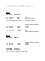
TABLE OF CONTENTS
(AU FUNDED)
SINGLE PRIME CONTRACTS
(Revised January 2012)
Native American Collection Foy Hall Basement
Project 11-221
I. Proposal Documents
A. Standard Documents
1.
INSTRUCTIONS TO BIDDERS
ABC Form C-2 (Aug. 2001)
2.
PAGES
SUPPLEMENTAL INSTRUCTIONS TO BIDDERS
9
2
AU Form C-2 SIB (November 2011)
3.
SALES AND USE TAX EXEMPTION
AU Form C-2A SUTE (April 2011)
4.
PROPOSAL FORM
ABC Form C-3 (Aug. 2001)
5.
2
FORM OF BID BOND
ABC Form C-4 (Aug. 2001)
6.
10
1
BID OPENING INSTRUCTIONS
(October 2009)
1
B. Project Specific Documents
1.
ADVERTISEMENT FOR BIDDER TO REGISTER
3
AND PRE-QUALIFY
(Rev. April 2011)
2. #SPECIAL INSTRUCTIONS TO BIDDERS
AU Form B (October 2009) (Rev. 01/07/12)
3. ATTACHMENT A TO PROPOSAL FORM
1
1
LIST OF SUB-CONTRACTORS AND MAJOR SUPPLIERS
AU FORM C-3A (Rev. 7/29/2008)
4. ATTACHMENT B TO PROPOSAL FORM
2
STATED ALLOWANCES AND UNIT PRICES
AU FORM C-3B (Rev. 7/12/2007)
II.
Conditions of The Contract
Standard Documents
A.
1.
CONSTRUCTION CONTRACT
2
ABC Form C-5 (Rev. 4/13/2011)
2.
ATTACHMENT A TO CONSTRUCTION CONTRACT
2
AU FORM C-5A (March 2002)
3.
ATTACHMENT B TO THE CONSTRUCTION CONTRACT
ATTACHMENT B: HEALTH AND SAFETY
Auburn University Safety Specification – Construction
Contracts – Single Prime Contract (October 2010)
4.
12
#ATTACHMENT C TO THE CONSTRUCTION CONTRACT
AU Form C-5B (December 2011)
5.
1
APPENDIX A TO ATTACHMENT B
Project Site Safety Plans (March 2010)
6.
3
APPENDIX B TO ATTACHMENT B
Activity Hazard Analysis (March 2010)
7.
3
PERFORMANCE BOND
3
ABC Form C-6 (April 2011)
8.
PAYMENT BOND
2
ABC Form C-7 (August 2001)
9.
GENERAL CONDITIONS OF THE CONTRACT
53
ABC Form C-8 (Rev. 3/9/2007)
10. MANDATORY SUPPLEMENT TO THE GENERAL
CONDITIONS OF THE CONTRACT
2
ABC Form C-8S (August 2009)
11. SUPPLEMENTAL GENERAL CONDITIONS
7
AU Form C-8 SGC (Rev. 1/7/2012)
12. RELEASE OF LIEN FORM
1
(Rev. 7/12/2007)
13. FORM OF ADVERTISEMENT FOR COMPLETION
1
ABC Form C-14 (Rev. 7/12/07)
A.
Project Specific Documents
1. SPECIAL CONDITIONS*
2. TECHNICAL SPECIFICATIONS
1
on drawings
3. HARDWARE SCHEDULE*
5
4. HARDWARE CUT SHEETS*
76
5. EQUIPMENT CUT SHEETS*
31
6. 13010 ASBESTOS REMOVAL*
15
# Additional Conditions required by the New Immigration Law (Act 2011-535)
* Revised or added per Addendum No. 1
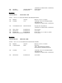
SPECIAL CONDITIONS
1. TIME OF COMPLETION
Work in this contract shall be substantially completed by August 1, 2012, assuming the Notice to
Proceed is issued as stated below.
2. NOTICE TO PROCEED
The intended Notice to Proceed is May 1, 2012. In the event that the NTP is later than the stated date,
the date of Substantial Completion shall be increased the same number of days the NTP is issued
beyond the above date.
3. LIQUIDATED DAMAGES
See Section 49 of the ABC Form C-8, General Conditions.
4. PROJECT SIGN:
A project sign is not required for this project.
5. RAIN DAY CLASS:
For the purpose of granting time extensions due to rain, this project is considered a Class V project.
6. BUILDER’S RISK INSURANCE:
To be provided by General Contractor.
7. COORDINATION WITH ADJACENT PROJECT:
General Contractor and its subcontractors shall coordinate with the work being performed
simultaneously with AU Project 11-201, Pharmacy Care Systems, in the same space. Contractors
shall determine coordinated scope and schedule prior to construction and shall present the
coordination plan to the AU Project Manager.
8. GYPSUM BOARD JOINT COMPOUND PRECAUTIONS
It has been determined that the joint compound used in some of the gypsum board wall assemblies
contains trace amounts of less than 1% asbestos. Although this amount is not considered Asbestos
Containing Material (ACM) per EPA and OSHA thresholds, the General Contractor is required per
OSHA to protect workers from any airborne asbestos exposure.
9. PROJECT SUBMITTALS / SCHEDULE:
All submittals will be required for this project and a detailed schedule including submittal issue and
return dates will need to be prepared and delivered to the AU Project Manager prior to start of
construction. The schedule will need to be updated weekly and will be reviewed at weekly on site
meetings with the AU PM.
G:\Design & Construction Services\Projects\2011\11-221\Project Manual\24_Special Conditions_042909 REV.doc
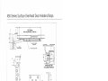
AUBURN UNIVERSITY – NATIVE AMERICAN COLLECTION
ARCHITECTS PRE-LIMINARY HARDWARE SCHEDULE – 03.30.12
IT’S THE VENDORS RESPONSIBILITY TO REVIEW THE ARCHITECTS DRAWINGS AND MODIFY
THE SCHEDULE AND CUT SHEETS AS REQUIRED. HEADINGS ARE REFERENCED ON THE
DOOR SCHEDULE DRAWING A1.0.
HEADING 1
1 SGL DOOR C103
VESTIBULE RHR
TYPE B - (V.I.F.) X (V.I.F.) FLUSH INSULATED METAL DOOR X HM WELDED FRAME
1 EA
3 EA
DOOR SWEEP
HINGES
PEMKO
HAGER
315CN x 36”
BB1279 X 4.5 X 4.5 X US26D
1 EA
FIRE EXIT HARDWARE VON DUPRIN
98L-NL-F E996L 3’ FS 06 626
(AUBURN TO VERIFY SPEC. & OPTIONS)
1 EA
CLOSER
LCN
4041 DEL X STANDARD FINISH
ARM-REGULAR
(AUBURN TO VERIFY SPEC. & OPTIONS)
3 EA
1 EA
1 SET
1 EA
1 EA
SILENCERS
THRESHOLD
JAMB SEAL
HEAD SEAL
POWER SUPPLY
ROCKWOOD
PEMKO
PEMKO
PEMKO
VONDUPRIN
1 EA
CARD READER
BEST
608 X GRAY
171A x 36”
290AS x 2pcs 84”
2891AS x 36”
PS861
(AUBURN TO VERIFY SPEC. & OPTIONS)
IDH MAX
(SPEC. PROVIDED BY AUBURN)
SEE NOTES & COMMENTS BELOW.
HEADING 2
1 SGL DOOR 104
OFFICE LH
TYPE A - 3/0X7/0 FLUSH SCWD DOOR X HM WELDED FRAME
3 EA
1 EA
HINGES
CLASSROOM LOCK
HAGER
BEST/STANLEY
1 EA
3 EA
WALL STOP
SILENCERS
ROCKWOOD
ROCKWOOD
BB1279 X 4.5 X 4.5 X US26D
F84-93K-7-R-15-D-STK-626
(AUBURN TO VERIFY SPEC. & OPTIONS)
406 X US32D
608 X GRAY
HEADING 3
1 SGL DOOR 103
1 SGL DOOR 110A
STORAGE LH
STORAGE LHR
TYPE A - 3/0X7/0 FLUSH SCWD DOOR X HM WELDED FRAME
6 EA
2 EA
HINGES
STOREROOM LOCK
HAGER
BEST/STANLEY
BB1279 X 4.5 X 4.5 X US26D
F86-93K-7-D-15-D-STK-626
2 EA
6 EA
OH STOP
SILENCERS
GLYNN JOHNSON
ROCKWOOD
(AUBURN TO VERIFY SPEC. & OPTIONS)
454S X US32D
608 X GRAY
HEADING 4
1 SGL DOOR 110
WORK AREA LHR
TYPE C - 3/0X7/0 12” LITE SCWD DOOR X HM WELDED FRAME
3 EA
1 EA
HINGES
CLOSER
HAGER
LCN
BB1279 X 4.5 X 4.5 X US26D
1461X DEL X FC X STANDARD FINISH
ARM-REGULAR
(AUBURN TO VERIFY SPEC. & OPTIONS)
1 EA
CLASSROOM LOCK
BEST/STANLEY
F84-93K-7-R-15-D-STK-626
(AUBURN TO VERIFY SPEC. & OPTIONS)
1 EA
3 EA
1 EA
1 EA
WALL STOP
SILENCERS
KICKPLATE
KICK DOWN HOLDER
ROCKWOOD
ROCKWOOD
ROCKWOOD
ROCKWOOD
406 X US32D
608 X GRAY
K1038 X 12” X 34” X CSK X S. STEEL
461 X US26D
HEADING 5
1 SGL DOOR 110B
PREP AREA RHR
TYPE B - 3/0X (V.I.F.) FLUSH HM DOOR X HM WELDED FRAME
3 EA
1 EA
HINGES
CARD READER
HAGER
BEST
BB1279 X 4.5 X 4.5 X US26D
IDH MAX
(SPEC. PROVIDED BY AUBURN)
SEE NOTES & COMMENTS BELOW.
1 EA
CLOSER
LCN
1461X DEL X FC X STANDARD FINISH
ARM-REGULAR
(AUBURN TO VERIFY SPEC. & OPTIONS)
3 EA
SILENCERS
ROCKWOOD
608 X GRAY
INOX - GENERAL NOTES & COMMENTS
1. Control sample to be provided to Architect for review and approval.
2. Flush doors will be furnished as VT Industries 5502 series or equal with
particleboard core.
3. Interior hollow metal frame will be furnished as 16 gauge, welded, primed for field
painting. All doors and frames to have a sprayed vs. brushed final finish.
4. Contractor to verify transitions and doors to be undercut. Where ventilation is
required doors to be undercut ½”.
5. See A1.0 for additional door, hardware notes and types.
6. Please coordinate with Auburn University Project Manager to determine keying
requirements.
7. Hinges will be furnished in US26D satin chrome plated finish. All other hardware
US32D satin stainless steel finish, except closers which are furnished in aluminum
painted finish to match or where noted to match existing.
AUBURN UNIVERSITY ACCESS CONTROL NOTES & COMMENTS:
*NOTE: This document is for aid in writing specifications for job proposal and is not
intended as a Literal Specification. All proposed Access Control specifications must be
approved by Auburn University Facilities Maintenance & Operations and AU Access
Control Center.
1)
All exterior doors shall be electrified and monitored by the LENEL system and software
and meet the requirements of the Access Control Installation Checklist.
2)
At least one exterior door shall have a 2010 card reader.
3)
MDF and IDF rooms shall have card reader access and shall have substantial space
provided for Access Control and Security systems.
4)
MDF and IDF rooms shall only be utilized by Auburn University Department of
Information Technology, Auburn University Access Control, and Auburn University
Department of Public Safety and Security without express written approval of all parties.
5)
Electrified exit devices shall be Von Duprin, EL RX 99/98 Series rim device, Electric
Latch Retraction with Request to exit (RQE), with keyed removable center mullions for
double egress doors. All electrified doors shall be installed as Night Latch function, so no
manual locking is required after hours. NO DOUBLE CYLINDER! NO DOGING
DEVICES!
6)
All ADA operators shall be LCN 4640 series, mounted on the push side of the door. On
any card access door, the door shall have both a swipe reader and a proximity reader to be
tied into the LENEL system.
7)
Door Closers:
Exterior Doors: LCN 4041 Series (No Substitutions Allowed)
Interior Doors: LCN 1461 Series (No Substitutions Allowed)
All door closers shall be mounted on the interior side of the room.
All door closers shall be equipped with “Delayed Action” feature.
8)
All lock hardware must accept BEST 7 pin, interchangeable cores.
9)
All interior door hardware shall be BEST 45H mortise or 9K cylindrical locks.
10)
All access control system control panels shall be mounted within a telecom closet. All
cabling shall be installed as to “Home Run” back to this area. Proper room shall be
allocated for necessary equipment. Circuits supplying AC voltage to the access control
system shall NOT provide power to any other system or devices.
11)
Any door that is monitored by access control system, but does not have a card reader shall
have a PIR (Motion Detector) or RQE (request to exit) device to mask exiting traffic.
12)
All power supplies and access control support systems shall be installed and connected to
the buildings Emergency Back-up Generator in addition to Battery Back-up.
Magnetic locks (mag locks) and/or Electric strikes shall NOT be used.
13)
14)
All Access Control power supplies shall be clearly labeled as to the door designation,
electrical panel, and circuit number from which it is supplied.
15)
Doors and frames shall accept an EPT (Electrified Power Transfer). Electrified hinges
should not be used.
END OF DOCUMENT
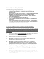
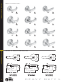
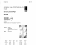
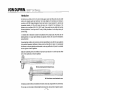
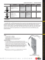
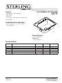
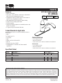
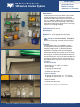
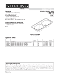
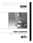
HEAVY DUTY LOCKS - LEVERS
HEAVY DUTY CYLINDRICAL LOCKS – LEVERS
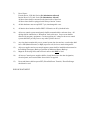
TABLE OF CONTENTS & FEATURES
TABLE OF CONTENTS
Page
Features ..............................................................2
Specifications ..............................................................3
How to Order ..................................................................3
Trim Variations ..............................................................4
Options/Features ................................................5
Service Equipment ......................................................5
Page
Function Descriptions . . . . . . . . . . . . . . . . . . . . . . . . .6-9
Shipping Weights . . . . . . . . . . . . . . . . . . . . . . . . . . . . .9
9K Sample Specifications . . . . . . . . . . . . . . . . . . . . . .10
Patented Keying . . . . . . . . . . . . . . . . . . . . . . . . . . . . .10
Deadlocking Latches . . . . . . . . . . . . . . . . . . . . . . . . . .11
Strikes & Door Preparation . . . . . . . . . . . . . . . . . . . . .11
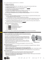
FEATURES
1. For versatile applications, lever by knob trim variations are available.
2. Rose locking pin and rose assembly design offers great torque resistance. It prevents the locking pin from twisting,
bending, or breaking under attack.
3. The innovative design of the slotted key release cam and locking lug assembly create maximum attack resistance.
Even though damaged, the lock still allows key access. In addition, the lever is fully functional from the inside.
The hub-mounted torsion spring and strong retractor springs help prevent lever sag and offer a smooth and snappy
operation.
4. Strong through-bolt mounting studs increase torque resistance.
Heavy rose liner material is highly attack resistant.
5. Strong retractor springs provide resistance to lever sag.
6. New zinc hubs with a shrouded locking lug, guaranteeing higher quality and increased torque resistance.
7. The outside lever sleeve is a seamless one piece construction made of a hardened steel alloy that provides additional
reinforcement in the locking lug slot.
8. Lost Motion feature available allowing lever movement between 45º – 60º without engaging retractor assembly.
9. Interchangeable core allows for quick re-keying and customized masterkeying.
3
2
4
1
5
6
7
8
9
9K – EXPLODED
2
H E AV Y
D U T Y
L
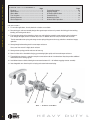
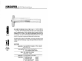
Latch – Solid brass 9/16" throw. Front 2 1/4" x 1 1/8" beveled.
Lever handles – Lever handles are a high-quality zinc alloy.
Trim components are brass or bronze. Body is approximately
1 5/8" in diameter; Handle is approximately 4 3/4" long (from
center-line of chassis). #14 and #15 levers conform to
California Administrative Code Title 19 and Title 24. All three
styles of levers conform to the Illinois Accessibility Standard.
American National Standard:
ANSI A156.2, Series 4000 Grade 1
California Fire Code NOA ANSI A250.13
Listed.
Finish – (BHMA) US
605
3
606
4
611
9
612
10
613
10B
618
619
622
625
626
690
Mounting – In addition to standard door preparation (ANSI
A115.2 for 1 3/4" doors), two additional holes are needed for
through-bolts. Through-bolts require two 5/16" diameter holes
located at 12 o'clock and 6 o'clock positions. A drill jig is
provided to insure accuracy of the holes. (see KD303 page 5).
DESCRIPTION
bright brass
satin brass
bright bronze
satin bronze
oxidized satin bronze,
oil rubbed
bright nickel plated
satin nickel plated
flat black
bright chromium plated
satin chromium plated
dark bronze
14
15
19
26
26D
20
Projection on door – Approximately 2 3/4" when mounted on
1 3/4" door.
Roses –
C
D
K
L
- 3" Convex
- 3 1/2" Convex
- 3" Convex - no ring
- 3 1/2" Convex - no ring
Strike– STK: Conforms to ANSI A115.2 (2 3/4" x 1 1/8" with
curved lip & box). S3: Conforms to ANSI A115.2 for 1 3/4"
doors (4 7/8" x 1 1/4" with curved lip). S3-7/8: Conforms to ANSI
A115.2 for 1 3/4" doors (4 7/8" x 1 7/8" flat)
Backset – 2 3/4" standard, 3 3/4" and 5" available.
Products protected by one or more of the following patents:
Chassis – Critical latch and chassis components are
brass or corrosion-treated steel. 2 1/16" diameter to fit
2 1/8" hole in door (Conforms to ANSI A115.2). Lost
Motion feature available as an option. (see page 5
for options/features)
D290,085
4,843,852
4,262,507
5,116,170
Door thickness – Available for 1 3/4" to 2 1/4" doors.
Spacers available for 1 3/8" doors.
U.S.:
4,428,212
4,318,558
4,496,178
5,590,555
Canada:
1,184,773
1,194,057
1,229,358
4,428,570
4,779,908
5,794,472
Other products patent pending.
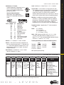
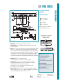
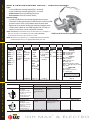
HOW TO ORDER
93K
7
AB
15
D
S3
626
Backset
Core
Housing
Function
Code
Lever
Style
Rose
Style
Strike
Package
Available
Finishes*
Options
605 606
611 612
613 618
619 622
625 626
690
AL– abrasive lever
LL– lead lined
LM– lost motion
RQE– request to exit
SH– security head screws
TL– tactile lever
3/4– 3/4" throw latch
7/8" LTC– flat lip strike
NOTE: specify inside (I),
outside (O), or both (B) for
AL,TL options
93K– 2 3/4" 0– keyless
94K– 3 3/4" 7– 7 pin
housing
95K– 5"
accepts
all Best
cores
AB– entrance 14– curved
D– storeroom
return
L– privacy
15– contour
N– passage
angle return
R– classroom 16– curved
Etc.
no return
pages 6-9
pages 4-5
C– 3" convex STK– 2 3/4"
D– 3 1/2"
ANSI
convex
S3– 4 7/8"
K– 3" convex
ANSI
- no ring
S3–
7/8- 7/8"
1
L– 3 /2"
flat strike
convex no ring
pages 4-5
page 11
HOW TO ORDER
Certifications – UL Listed:
Listed by Underwriter's Laboratories for use
on 3 Hr, A label single swinging doors
(4'x10'). GYJT Builders Hardware-single
point locks or latches.
SPECIFICATIONS
SPECIFICATIONS
page 5
* Handles are made from a zinc alloy, and have been plated to be equivalent in appearance to the finishes listed.
For information on 9K non IC products please refer to Best’s non-IC keying products brochure.
O C K
-
L E V E R S
3
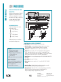
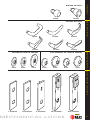
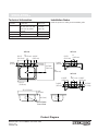
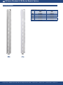
TRIM VARIATIONS
DIMENSIONS
4
TRIM VARIATIONS
14C
15C
16C
14D
15D
16D
14K
15K
16K
14L
15L
16L
LEVER & TRIM DIMENSIONS
H E AV Y
D U T Y
L
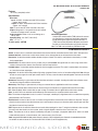
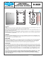
SERVICE EQUIPMENT
KD303 THROUGH-BOLT DRILL JIG
Special accessory jig aids in aligning 5/16" holes for through-bolt mounting. Install the
latch first, then insert jig in 2 1/8" bored hole, align with door edge and drill with 5/16" drill
bit. A drill jig is included 1 per every 9 locksets with your order. Additional jigs are available
upon request.
To order: designate KD303.
KD303-9K
KD304A BORING JIG KITS
The KD304A jig kit is made for boring cut outs in wooden doors for ANSI A156.2 series
cylindrical/tubular locksets, doors 1 3/8" to 2 1/4" thick. The KD304A kit includes the
boring jig (to drill wood doors for 2 3/8" , 2 3/4" , 3 3/4" and 5" backsets), adaptor for 3/8"
drill chuck, KD309: 2 1/8" bit, KD318: 1" dia. x 9" bit, KD312: face plate marking chisel
1", KD315: face plate marking chisel 1 1/8", and the KD325: strike plate locating pin.
To order: complete kits specify KD304A Kit. All of the individual kit parts listed above
may be ordered separately except for the adaptor chuck and jig.
OPTIONS/FEATURES
SERVICE EQUIPMENT
OPTIONS/FEATURES
Abrasive Lever Option
Besides complying with a wide variety of accessibility codes and ordinances, Best Access Systems lever handles are
available with a special abrasive feature. Abrasive strip on the lever immediately identifies warnings on doors to
hazardous areas for the blind. To order: Designate "AL" on How to Order (page 3). Note: abrasive strip is
available on all levers, except #14, #15, #16 levers in 613 finish.
Lost Motion Feature
The Lost Motion feature allows the lever handle to move 45 degrees from parallel to the horizontal plane without
engaging the latchbolt assembly. When the lockset is in the locked mode, this feature makes over-torque or overlever-age abuse more difficult to achieve. To order: designate "LM" on How to Order (page 3).
Non IC Lever Option
The 9K heavy duty cylindrical lock may be adapted to existing keying systems by using a special retrofit lever and throw
member that will accept 6 pin single shear-line cylinders from non BEST manufacturers. No internal modifications are
required to adapt the 9K to cylinders from the following manufacturers: Corbin-Russwin, Medeco, Sargent, Schlage,
Yale. Refer to non-IC Best keying products brochure for more details.
RQE Feature
The 9K lever handle cylindrical can be supplied with a request-to-exit (RQE) switch. A normally open switch provides
momentary switch closure when the inside lever is rotated. To order: designate "RQE" on How to Order (page 3).
Tactile Lever Option
Tactile levers may be used in areas where improved grip is required or as a warning in hazardous areas. Grooves are
machined into the back of the hand grasp portion of the lever to improve grip and/or to provide a sensory warning in
hazardous areas. This option can be used for Blind, Safety or Accessibility applications. To order: Designate "TL" on
How to Order (page 3).
KD304A
(Complete kit)
KD315 FACE PLATE MARKING CHISEL
KD325 PLATE LOCATING PIN
The KD315 faceplate marking chisel locates the mortising for the faceplate of
ANSI A156.2 (1 1/8" x 2 1/4" ) cylindrical lockset. A strike plate locating pin KD325
is available for use in conjunction with ANSI A156.2 cylindrical locksets.
To order: designate KD312 faceplate marking chisel (1"), KD315 faceplate marking
chisel (1 1/8"), KD325 strike plate locating pin.
KD317 SPANNER WRENCH
KD340 SPRING TOOL
All 9K locksets require the use of KD317 spanner wrench for door mounting.
This tool is included 1 per every 9 locksets with your order. If more are needed,
designate KD317 on your order. The KD340 lever return spring tool with its
unique design feature is used when replacing the 9K lever return spring.
To order: designate KD340.
KD315
KD325
KD340
Spring Tool
KD317
Spanner Wrench
O C K
-
L E V E R S
5
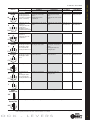
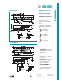
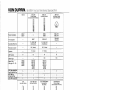
FUNCTIONS
FUNCTIONS
Function & Diag.
(ANSI No.)
Single Keyed
Entrance
AB
F109
Storeroom
D
Description
Latch operated by
Outside Lever
Locked by
Unlocked by
• Rotating the inside lever,
• Pushing the inside button,
• Rotating the outside
• Pushing and turning the
lever—only when the inside inside button. Turning the
push button is out,
button keeps the outside
• Turning the key in the
lever locked until the button
outside lever
is turned back
• Turning the key in the
outside lever,
• Rotating the inside lever
Always fixed
Inside Lever
Locked by
Unlocked by
• Turning the key in the outside Cannot be locked
lever, (only when the button is
not turned)
• Rotating the inside lever, (only
when the button is not turned).
• Closing the door (only when
the button is not turned)
Always unlocked
Cannot be locked
Always unlocked
• Turning the key in the outside
lever,
• Rotating the inside lever,
• Closing the door-only when
the button is not turned,
• Turning back the slotted
button
Cannot be locked
Always unlocked
Key block feature is
released by:
• Rotating the inside lever,
• Closing the door
Cannot be locked
Always unlocked
Cannot be unlocked
F86
Service Station
E
F92
Hotel Guest Rm.
H
F93
Indicator
Included
Hotel Guest Rm.
HJ
No Indicator
• Rotating the inside lever,
• Rotating the outside
lever-only when the inside
push button is out.
• Turning the key in the
outside lever
• Rotating the inside lever,
• Turning the key in the
outside lever-only when the
inside push button is out,
• Removing the core with a
control key and using a
special emergency key
Pushing the inside button projects an “occupied” indicator in the outside lever and blocks all operating keys.
• Rotating the inside lever,
• Turning the key in the
outside lever,
• Rotating the outside lever
when not locked by key
Dormitory
• Rotating the inside lever,
• Rotating the outside lever
when not locked by key or
push button
F84
T
F90
Double Keyed*
Corridor
C
F88
Storeroom *
G
F91
Always fixed
Always fixed
Key block feature is
• Rotating the inside lever,
released by:
• Turning the key in the
• Rotating the inside lever,
outside lever-only when the
• Closing the door
inside push button is out,
• Removing the core with a
control key and using a
special emergency key
Pushing the inside button blocks all operating keys, but no “occupied” indicator is projected.
Classroom
R
• Pushing the inside button,
• Pushing and turning the
inside button. Turning the
button keeps the outside
lever locked until the button is
turned back
Cannot be locked
Always unlocked
Turning the key in the outside
lever
Cannot be locked
Always unlocked
• Turning the key in the outside • Turning the key in the outside
lever,
lever,
• Rotating the inside lever (only
• Pushing the button on the
when locked by push button),
inside lever
• Closing the door (only when
locked by push button)
Cannot be locked
Always unlocked
Cannot be locked
Always unlocked
Turning the key in the outside
lever
• Rotating the inside lever,
• Rotating the outside lever
when not locked by key,
• Turning the key in the
outside lever
Turning the key in the inside
lever
• Rotating the outside lever
when not locked by key,
• Rotating the inside lever
when not locked by key
• Turning the key in the inside
lever,
• Turning the key in the
outside lever
Turning the key in the inside
lever
• Turning the key in the inside
• Turning the key • Turning the key
lever,
in the inside lever, in the inside lever,
• Turning the key in the outside • Turning the key • Turning the key
lever
in the outside
in the outside
lever
lever
Turning the key in either the inside or the outside, locks or unlocks both sides.
*ATTENTION: Locksets that secure both sides of the door are controlled by building codes and the Life Safety Code. In an emergency exit situation,
failure to quickly unlock the inside lever could be hazardous or even fatal.
6
H E AV Y
D U T Y
L
Function & Diag.
(ANSI No.)
Description
Latch operated by
Outside Lever
Locked by
Double Keyed (Continued)
• Rotating inside lever,
Intruder
• Turning key in the inside
• Rotating outside lever
lever,
only when not locked by • Turning the key in the
inside or outside key
outside lever
IN
Communicating*
S
F80
Institutional*
W
Unlocked by
Inside Lever
Locked by
Unlocked by
• Turning key in the inside
Cannot be locked
lever,
• Turning the key in the outside
lever
• Turning the key in the
Turning the key in the outside Turning the key in the outside
inside lever,
lever
lever
• Turning the key in the
outside lever,
• Rotating the inside or
outside lever (if unlocked)
Turning the key in either lever, locks or unlocks its own lever independently.
Cannot be unlocked
Always unlocked
Turning the key in
the inside lever
Turning the key in
the inside lever
Always fixed
Cannot be unlocked
Cannot be locked
Always unlocked
• Turning the key in the
inside lever,
• Turning the key in the
outside lever
Always fixed
• Rotating the inside lever
• Rotating the outside
lever only when the
inside push button is out
Pushing the inside button
Passage
• Rotating the inside lever,
• Rotating the outside
lever
Cannot be locked
Always unlocked
Cannot be locked
Always unlocked
Exit
Rotating the inside lever
Always fixed
Always fixed
Cannot be locked
Always unlocked
Patio
• Rotating the inside
lever,
• Rotating the outside
lever only when the
inside push button is out
Cannot be locked
Always unlocked
Exit
Rotating the inside lever
Cannot be locked
Always unlocked
FUNCTIONS
FUNCTIONS
F87
Keyless
Privacy
L
• Rotating the outside slotted
button,
• Rotating the inside lever,
• Closing the door.
F76
N
F75
NX
F89
P
F77
Pushing the inside button
• Rotating the inside lever,
• Closing the door
Y
Single
Dummy Trim
This is a single, surface-mounted lever for an inactive door or a non-latching door
1DT
Double
Dummy Trim
This is a through bolt mounted pair of matching levers for an inactive door or a non-latching door
2DT
*ATTENTION: Locksets that secure both sides of the door are controlled by building codes and the Life Safety Code. In an emergency exit situation,
failure to quickly unlock the inside lever could be hazardous or even fatal.
O C K
-
L E V E R S
7
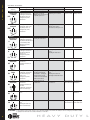
FUNCTIONS
FUNCTIONS
Function & Diag.
(ANSI No.)
Description
Latch operated by
Electromechanical
• Rotating the inside lever,
Electrically
Locked
• Rotating the outside lever
only when power is off,
DEL
Locked by
Outside Lever
Unlocked by
• Applying 24 Volts DC.
• Outside lever remains locked
only while power is on
Inside Lever
Locked by
Unlocked by
Cannot be locked
Always unlocked
• Applying 24 Volts DC
Cannot be locked
• Outside lever remains
unlocked only while power is on
Always unlocked
Switching off 24 Volts DC
• Turning the key in the
outside lever
Electrically
Unlocked
DEU
Special
Dormitory or
Storeroom
A
F81
• Rotating the inside lever,
• Rotating the outside lever
only when power is on,
• Turning the key in the
outside lever
Switching off 24 Volts DC
• Rotating the inside lever,
• Rotating the outside lever
only when inside turn button
is in unlocked position,
• Turning the key in the
outside lever
Turning the inside button
B
F82
Closet or
Storeroom
DZ
• Turning the key in the
outside lever,
• Turning the inside closet
turn knob
Entrance or
Office
EA
• Rotating the inside lever,
• Rotating the outside lever
only when inside push
button is out,
• Turning the key in the
outside lever
Closet or
Storeroom
• Turning the key in the
outside lever,
• Turning the inside closet
turn knob,
• Rotating the outside lever
when not locked by key
Always unlocked
Always fixed
Cannot be unlocked
• Pushing the inside button,
• Turning the key in the outside
• Pushing and turning the
lever,
inside button. Turning the
• Rotating the inside lever,
slotted button keeps the
• Turning the slotted button back
outside lever locked until the
button is turned back
Closet turn knob
cannot be locked
Closet turn knob
always free
Cannot be locked Always unlocked
Turning the key in the
outside lever
Turning the key in the
outside lever
Closet turn knob
cannot be locked
Closet turn knob
always free
Special*
Turning the key in the inside
lever
Always fixed
Cannot be unlocked
Always fixed
Cannot be
unlocked
Special*
• Turning the key in the inside
lever,
• Rotating the inside lever
when not locked by key
Always fixed
Cannot be unlocked
Turning the key
in the inside lever
Turning the key
in the inside lever
XD
XR
Cannot be locked
NOTE: Turn button must be manually rotated to unlock the outside lever.
• Rotating the inside lever,
Pushing the inside button
• Turning the key in the outside Cannot be locked Always unlocked
• Rotating the outside lever
lever,
only when inside push
• Rotating the inside lever
button is out,
• Turning the key in the
outside lever
NOTE: Push button is released by turning the key in the outside lever, OR rotating the inside lever. Closing the door does not release the push button.
Office
RZ
Turning the inside button
*ATTENTION: Locksets that secure both sides of the door are controlled by building codes and the Life Safety Code. In an emergency exit situation, failure
to quickly unlock the inside lever could be hazardous or even fatal.
8
H E AV Y
D U T Y
L
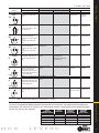
Function & Diag.
(ANSI No.)
Description
Latch operated by
Locked by
Inside Lever
Locked by
Unlocked by
Outside Lever
Unlocked by
Special (Continued)
Turning the key in the inside
Exit *
lever
YD
Cannot be
unlocked
Always fixed
Special *
• Turning the key in the inside
lever,
• Rotating the inside lever when
not locked by key
Special *
• Rotating the inside lever only
when not locked by key,
• Turning the key in the outside
lever,
• Turning the key in the inside
lever
Always fixed
Cannot be unlocked
Turning the key in Turning the key
the inside lever
in the inside lever
Special *
• Rotating the outside lever only
when not locked by key,
• Turning the key in the outside
lever,
• Turning the key in the inside
lever
Turning the key in the
outside lever
Turning the key in the
outside lever
Always fixed
Cannot be
unlocked
Hospital
Privacy
• Rotating the inside lever,
• Rotating the outside lever only
when the inside push button is
out
Pushing the inside push
button
Cannot be locked
Always unlocked
Communicating*
M
• Rotating the inside lever-only
when the outside turn button is
in the unlocked position,
• Rotating the outside lever-only
when the inside turn button is in
the unlocked position
Turning the inside turn
button
YR
DR
RD
LL
F78
FUNCTIONS
FUNCTIONS
Turning the key in Turning the key
the inside lever
in the inside lever
• Turning the turn button in
the outside lever,
• Rotating the inside lever,
• Closing the door
Turning the inside turn button
Turning the outside Turning the outside
turn button
turn button
NOTE: Do not use this function for rooms that have no other entrance.
Exit
Q
• Rotating the inside lever,
• Rotating the outside lever-only
when the inside turn button is in
the unlocked position
Turning the inside turn
button
Turning the inside turn button
Cannot be locked
Always unlocked
• Rotating the outside lever,
• Turning the inside closet turn
knob
Cannot be locked
Always unlocked
Closet turn knob
cannot be locked
Closet turn knob
is always free
F83
Closet
Z
*ATTENTION: Locksets that secure both sides of the door are controlled by building codes and the Life Safety Code. In an emergency exit situation,
SHIPPING WEIGHTS
The chart is the approximate shipping weight for the standard 9K functions locksets. This weight includes the weight of the
lockset with the “#15” style lever, “K” style rose, latch, strike package, and box. Listed separately are the approximate weights
for “with core” and “less core” shipments.
LOCK
FUNCTION
NOMENCLATURE
Y
N
L,NX,P
AB,D,E,H,HJ,R,T
C,G,IN,S,W
O C K
-
CASE
QUANTITY
L E V E R S
9
9
9
9
9
SHIPPING
WEIGHTWITH CORE
42lbs.
44 lbs.
SHIPPING
WEIGHTLESS CORE
31 lbs.
40 lbs.
40 lbs.
40 lbs.
40 lbs.
SHIP WEIGHTS
failure to quickly unlock the inside lever could be hazardous or even fatal.
9
SAMPLE SPECIFICATIONS
ACCEPTABLE MANUFACTURERS
A. Locksets and Latchsets
Stanley/Best - No Substitution.
1.
2.
3.
4.
5.
6.
7.
8.
9.
Locksets and latchsets: ANSI A156.2, Series 4000, Grade 1 UL listed, extra heavy-duty cylindrical type.
Backset 2 3/4 inches (70mm)
Interchangeable core 7-pin: [Restricted keyway] [Patented] [Standard] [
].
Locksets to have anti-rotational studs that are through-bolted.
Keyed lever with no exposed keeper hole.
Each lever to have independent spring mechanism designed to control lever only.
Outside lever sleeve seamless, 1-piece construction, hardened steel alloy.
Keyed Lever: Removable only after core is removed, by authorized control key, to allow access to knob keeper.
Hub, side plate, anti-rotational studs 1-piece casting with shrouded locking lug.
B. Keys and Keying
A. Cylinders: 7-pin, interchangeable core and keyed into a [New] [Existing] factory registered Grand Masterkey System
with a [Standard] [Restricted] [Patented] keyway.
1. Acceptable Material: Cylinders as manufactured by Best Access Systems.
B. Provide construction cores and keys during construction period. Construction control and operating keys and cores are
not part of permanent keying system or furnished on same keyway (or key section) as permanent keying system.
C. Permanent Keys and Cores: Prepare permanent cores and keys in accordance with keying schedule. [Stamp with
applicable key mark for identification.] [Do not stamp.] [
].
D. Provide Grand Masterkeys, Masterkeys and other Security Keys.
E. Furnish keys in the following quantities:
1. [4] [
] each Grand Masterkeys.
2. [4] [
] each Masterkeys per set.
3. [2] [
] each Change keys each keyed core.
4. [6] [
] each Construction masterkeys.
5. [2] [
] each Control keys.
6. Install permanent cores in locksets.
MX8 – PATENTED KEYING SYSTEM
F. Return construction cores to [{Best} factory representative] [Hardware manufacurer’s representative].
10
MX8 – PATENTED KEYING SYSTEM
One of the greatest threats to key control within your facility is the unauthorized duplication
of keys; one simple solution is the use of the MX8 Patented Keying System by Stanley-Best
Access Systems a patent-protected keying system.
Very seldom can a single product meet all of your exact needs, and often your level of
convenience must be sacrificed to fit the capabilities of the product. The MX8 Patented
Keying System provides you with an significant amount of flexibility, enabling a solution
that fits your unique balance between security and convenience.
The MX8 Patented Keying System is available in two series of keyways, the M Series
and the X Series. Each series offers a different blend of features to help you maximize
convenience while optimizing your security.
MX8 Key & Core
The MX8 Patented Keying System has the ability to provide geographic exclusivity to the customer.
M Series Keyway Features
• Patented keys operate both MX8 and Standard BEST cores (backward compatibility) with existing BEST keyways (JKLM only).
Standard keys do not operate MX8 cores.
• Available in large bow, long blade, and long nose key blanks to work with special applications.
• Available in core designs for use in special application locks, such as high security mortise, hotel cylinders, and glass display-case locks.
• Utilizes the same combinating kits and key cutting equipment as the Standard BEST keyways.
• M Series keys operate MX8 cores and Standard (non-patented) BEST cores. Standard key blanks do not operate MX8 cores.
X Series Keyway Features
• Distinctive key design includes thicker key blanks with larger bow for added strength and easier handling.
• Keyways are unique to MX8 Patented Keying System offering even higher key duplication protection.
• Requires only minor modifications to key cutting equipment to accommodate new keyways. X Series keyways utilize the standard
combinating kit, minimizing the expense of system changeover.
• X Series keys only operate MX8 cores.
H E AV Y
D U T Y
L
How to Order (page 3).
8KL5 Deadlocking Latch
Bolt throw– 9/16"
Backset– 5"
Front– 2 1/4" x 1 1/8" beveled.
Tube– To fit 1" diameter hole in door edge.
To order: (with unit) designate “95K” on
How to Order (page 3).
To order: (without unit) designate “8KL3-SL” To order: (without unit) designate “8KL4-SL" To order: (without unit) designate “8KL5-SL”
(Spring Latch) or DL (Deadlocking Latch)
and finish.
(Spring Latch) or DL (Deadlocking Latch)
and finish.
(Spring Latch) or DL (Deadlocking Latch)
and finish.
STRIKES
8KS3-7/8
8KS3
8KS3–7/8 Flat Strike
Dimension: Conforms to ANSI A115.2
8KS3 Strike
Dimension: Conforms to ANSI A115.2
8KS2 Strike (Supplied Standard)
Dimension: Conforms to ANSI A115.2
for 1 3/4" doors (4 7/8" x 1 7/8" flat)
To order: (with unit) designate “S3-7/8”
on How to Order (page 3).
To order: (without unit) designate
8KS3-7/8 and finish.
for 1 3/4" doors (4 7/8" x 1 1/8" with
curved lip).
To order: (with unit) designate “S3”
on How to Order (page 3).
To order: (without unit) designate
8KS3 and finish.
for 1 3/8" doors (2 3/4" x 1 1/8" with
curved lip and box).
To order: (with unit) designate “STK”
on How to Order (page 3).
To order: (without unit) designate
8KS2 and finish.
8KS2
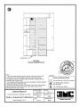
STRIKES & DOOR PREPARATION
STK strike (standard)
O C K
-
S3 strike
L E V E R S
DEADLOCKING LATCHES
How to Order (page 3).
8KL4 Deadlocking Latch
Bolt throw – 9/16"
Backset– 3 3/4"
Front– 2 1/4" x 1 1/8" beveled.
Tube– To fit 1" diameter hole in door edge.
To order: (with unit) designate “94K” on
STRIKES & DOOR PREP.
8KL3 Deadlocking Latch
Bolt throw– 9/16"
Backset– 2 3/4"
Front– 2 1/4" x 1 1/8" beveled.
Tube– To fit 1" diameter hole in door edge.
To order: (wit h unit) designate “93K” on
STRIKES
DEADLOCKING LATCHES
9K door preparation with
through-bolt mountings
11
HEAVY DUTY CYLINDRICAL LOCKS – LEVERS
For more information on Stanley Security Solutions’ products, services, and office locations visit our web site at www.stanleysecuritysolutions.com
Product information contained in this catalog has been compiled and presented with as much care and completeness as is reasonably possible. Errors
or mistakes may be present, and in many cases, reliance has been placed on information supplied by other manufacturers which may be in error or
which may be subject to changes or modifications by the manufacturer without notice and without obligation. Therefore, no guarantee can be made or
should be assumed or implied with regards to product information contained in this catalog.
Stanleyy Securiity Solutions, Inc.
6161 E. 75th Street Indianapolis, Indiana 46250
www.stanleysecuritysolutions.com
© 2009 Stanley Security Solutions, Inc. and Stanley Logistics
7.5M R709FP
BAS008
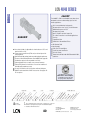
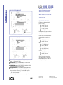
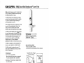
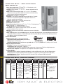
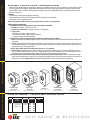
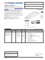
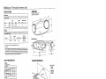
Designed for maximum
CLOSER MOUNTS
*HINGE (PULL) SIDE
TOP JAMB (PUSH SIDE)
PARALLEL ARM (PUSH SIDE)
versatility, the 1460, available
with multiple cover options, can
be used for both commercial and
institutional applications. This
fully universal closer offers a
wide variety of options and new
fast and accurate installation.
UL and cUL listed for self-closing
doors without hold-open. Tested and
certified under ANSI Standard
A156.4, grade one.
*HINGE (pull) side mount shown
Standard 1460 series closer shipped with regular arm, a slim line plastic
cover, and self reaming and tapping screws. See 1460 Series Pages 16 &
17 for options.
Multiple cover options include; Standard (Slim line), Full and Designer
Series.
Non-sized (1-6) cylinder is adjustable for interior doors to 5’0” and exterior
doors to 4’0”.
Closer mounts hinge side, top jamb and parallel arm on either right or left
swinging doors.
Closer meets ADA requirements. See 1460 Series page 18.
Standard or optional custom powder coat finish.
Optional plated finish on Designer Series metal cover, arm and fasteners.
Optional SRI primer for installations in corrosive conditions.
N-
NO
D
Available
Not available
*ARM FUNCTION
HA
N
N- DE
D
SI
AC ZE
CE D
S
DE SIB
LA ILI
YE TY
D
AC
TI
ON
RE
GU
LA
ST R (D
AN
OU
D
B
HE ARD LE)
AV (S
IN
Y
HO DU GLE
LD TY )
ED OPE
N
A/
H
CU EDA
SH
/
SC HCU
US SH
H/
SH
CU
SH
CYLINDER
NO
AS
TI
C
ET
AL
DE
SI
GN
ER
M
PL
DE
R
AT CO
ED AT
W
PL
PO
HI
NG
E(
TO PUL
L)
P
SI
J
TO AM DE
B
P
JA (PU
PA MB LL)
RA
(
L PU
ST LEL SH
OP AR )
FA M
CE
COVER
SE
RI
ES
FINISH
MOUNTING
180°
180° 180° 110° 100° 100°
Closer available with less than 5.0 lbs. opening force on 36" door.
* Maximum opening/hold-open point with standard template.
D = For Designer series only.
11
LCN CLOSERS
121 W. RAILROAD AVE.
P.O. BOX 100
PRINCETON, IL, USA 61356-0100
PHONE 800-526-2400
FAX 800-248-1460
www.lcn.ingersollrand.com
3/10
FEATURES
LCN 1460 SERIES
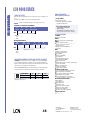
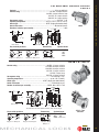
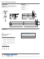
MOUNTING DETAILS
LCN 1460 SERIES
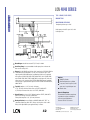
HINGE (PULL) SIDE
MOUNTING
MAXIMUM OPENING
110°
A = 5 7/8” (149 mm)
B = 10 7/8” (276 mm)
or *180°
A = 2 7/8” (73 mm)
B = 7 7/8” (200 mm)
Hold-open points up to maximum
opening with hold-open arm.
*Frame and trim permitting.
Optional, Non-handed
Designer Series
Metal Cover
Butt Hinges should not exceed 5” (127 mm) in width.
Auxiliary Stop is recommended at hold-open point or where a door
cannot swing 180°.
Reveal should not exceed 3/4” (19 mm) for regular arm or 1/2” (13 mm)
for hold-open arm.
Options
Delayed action cylinder.
Hold-open arm.
Full cover. (FC)
Designer Series metal cover. (DS1)
Special Templates
Customized installation templates
or products may be available to
solve unusual applications.
Contact LCN for assistance.
Top Rail less than 2 1/2” (64 mm) requires PLATE, 1460-18.
With Full cover, use PLATE, 1460-18FC. Plate requires 1 1/2” (38 mm)
minimum. With Designer Series metal cover, use PLATE, 1460-18DS1.
Clearance of 2 3/8” (60 mm) behind door required for installation.
Delayed Action Add suffix “DEL” to selected cylinder (eg. 1461 DEL).
Delays closing from 110° to 65° or 160° to 75° depending on
templating.
Delay time adjustable up to approximately 1 minute.
12
LCN CLOSERS
121 W. RAILROAD AVE.
P.O. BOX 100
PRINCETON, IL, USA 61356-0100
PHONE 800-526-2400
FAX 800-248-1460
www.lcn.ingersollrand.com
3/10
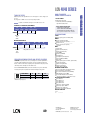
TOP JAMB (PUSH SIDE)
MOUNTING
MAXIMUM OPENING
110°
A = 6 3/4” (169 mm)
B = 11 1/4” (286 mm)
180°
A = 3” (76 mm)
B = 7 1/2” (191 mm)
Hold-open points up to maximum
opening with hold-open arm.
1460 - 18
Optional, Non-handed
Designer Series
Metal Cover
Butt Hinges should not exceed 5” (127 mm) in width.
Auxiliary Stop is recommended at hold-open point or where a door
cannot swing 180°.
Reveal of 2 1/2” (64 mm) allows 180° opening with REGULAR HOLD-OPEN
ARM. 3 1/2” (89 mm) allows up to 180° opening with REGULAR ARM or
180° with optional LONG HOLD-OPEN ARM when standard head and tube
is replaced with optional LONG HEAD AND TUBE, 1460-78HL . 4 7/8” (124
mm) allows up to 140° with REGULAR ARM or LONG HOLD-OPEN ARM.
Options
7” (178 mm) allows up to 140° opening with LONG ARM when standard
Delayed action cylinder.
rod and shoe is replaced with optional LONG ROD AND SHOE, 1460-79LR.
Long arm, hold-open arm,
long hold-open arm.
Top Rail requires 1 7/8" (48 mm) minimum.
Full cover (FC).
2 3/4" (70 mm) minimum with closer on PLATE, 1460-18.
Designer Series metal cover (DS1).
Head Frame less than 1 3/4” (44 mm) requires PLATE, 1460-18.
For flush ceiling condition with 2” (51 mm) headframe, use PLATE,
Special Templates
1460-18. With Full cover, use PLATE, 1460-18FC.
Customized installation templates or
Plate requires 1 1/4” (32 mm) minimum. With Designer Series
products may be available to solve
metal cover, use PLATE, 1460-18DS1.
unusual applications.
Delayed Action Add suffix “DEL” to selected cylinder (eg. 1461 DEL).
Contact LCN for assistance.
Delays closing from 110° to 75° or 180° to 95° depending on templating.
Delay time adjustable up to approximately 1 minute.
13
LCN CLOSERS
121 W. RAILROAD AVE.
P.O. BOX 100
PRINCETON, IL, USA 61356-0100
PHONE 800-526-2400
FAX 800-248-1460
www.lcn.ingersollrand.com
3/10
MOUNTING DETAILS
LCN 1460 SERIES
MOUNTING DETAILS
LCN 1460 SERIES
PARALLEL ARM (PUSH SIDE)
MOUNTING
Optional mounting requires PA SHOE,
1460-62PA for REGULAR or HOLDOPEN arms. Add prefix "P" to closer
description (e.g. P1461). P1461 closer
includes 1460-201 FIFTH HOLE
SPACER to support PA SHOE.
MAXIMUM OPENING
Regular or hold-open arm can be
templated for 100°
A = 4 1/4” (108 mm)
B = 9 1/4 (235 mm)
or 180°.
A = 1 3/4” (44 mm)
B = 6 3/4” (171 mm)
1460 - 18PA
Hold-open points up to maximum
opening with hold-open arm.
1460 REGULAR or HOLD-OPEN MOUNT
Butt Hinges should not exceed 5” (127 mm) in width.
Auxiliary Stop is recommended at hold-open point, where a door
cannot swing 180°, or where CUSH-N-STOP arm is not used.
Options
Delayed action cylinder.
Hold-open, EDA, HEDA,
CUSH, HCUSH, SPRING CUSH or
SPRING HCUSH arm.
Full cover. (FC)
Designer Series metal cover. (DS1)
Clearance for 1460-62PA shoe is 4” (102 mm) from door face.
Special Templates
Customized installation templates or
products may be available to solve
unusual applications.
Contact LCN for assistance.
Stop Width minimum 1” (25 mm).
Top Rail less than 4 3/8” (111 mm) measured from the stop requires
PLATE, 1460-18PA. With Full cover, use PLATE, 1460-18PAFC. Plate
requires 1 3/4” (44 mm) minimum. Plate requires 1 1/4” (32 mm) minimum.
With Designer Series metal cover, use PLATE, 1460-18PADS1.
Head Frame flush or single rabetted requires PA FLUSH PANNEL ADAPTER,
1461-419.
Blade Stop clearance, requires 1/2” (13 mm) BLADE STOP SPACER,
1460-61.
Auxiliary Shoe, 1460-62A allows installation of regular arm with
overhead holder/stop. Special templating required.
Delayed Action Add suffix “DEL” to selected cylinder (eg. P1461 DEL).
Delays closing from maximum opening to approximately 75°.
Delay time adjustable up to approximately 1 minute.
14
LCN CLOSERS
121 W. RAILROAD AVE.
P.O. BOX 100
PRINCETON, IL, USA 61356-0100
PHONE 800-526-2400
FAX 800-248-1460
www.lcn.ingersollrand.com
3/10
1460 EDA MOUNT
1460 EDA or CUSH-N-STOP
MOUNTING
1460 closers ordered with EDA,
CUSH arms include 1460-201 FIFTH
HOLE SPACER to support the shoe.
MAXIMUM OPENING
EDA template allows 110°.
Hold-open point up to maximum
opening.
CUSH arms can be templated for
maximum opening/hold-open point at
85°,
A = 2 3/8” (60 mm)
B = 9 9/16” (243 mm)
90°,
A = 1 5/8” (41 mm)
B = 9 1/16” (230 mm)
or 100°.
1460 - 18PA
A = 5/8” (16 mm)
B = 8 1/16” (205 mm)
1460 CUSH MOUNT
Spring CUSH hold open points
are approximately 5° less than
dead stop point.
Clearance for 1460-62EDA or
CUSH shoe is 5 1/2” (140 mm)
from door face.
Head Frame flush or rabetted
requires PA FLUSH PANEL
ADAPTER, 1460-419.
EDA or CUSH ARM requires
SHOE SUPPORT, 1460-30 for fifth
screw anchorage where reveal is
less than 3 1/16” (78 mm).
1460 - 18PA
15
LCN CLOSERS
121 W. RAILROAD AVE.
P.O. BOX 100
PRINCETON, IL, USA 61356-0100
PHONE 800-526-2400
FAX 800-248-1460
www.lcn.ingersollrand.com
3/10
MOUNTING DETAILS
LCN 1460 SERIES
ACCESSORIES
LCN 1460 SERIES
CYLINDERS
CYLINDER, 1460-3071
Standard, non-handed cast iron cylinder assembly.
3071
ARMS
REGULAR ARM, 1460-3077
Non-handed arm mounts hinge side or top jamb.
P1460 closer includes PA SHOE, 1460-62PA required for
parallel arm mounting.
PA SHOE, 1460-62PA
Required for parallel arm mounting.
LONG ARM, 1460-3077L
Optional, non-handed arm includes LONG ROD AND SHOE,
1460-79LR for top jamb mount with deep reveals.
HEAVY DUTY REGULAR ARM, 1460-3077HD
Optional, heavy duty, forged, non-handed arm, mounts hinge
side, top jamb or parallel arm.
HEAVY DUTY LONG ARM, 1460-3077HDL
Optional, heavy duty, forged, non-handed arm. Includes long
rod and shoe, 1460-79LR for top jamb mounts with deep
reveals.
HOLD-OPEN ARM, 1460-3049
Optional, non-handed arm mounts hinge side, top jamb or
parallel arm (62PA required).
Hold-open adjustable at shoe.
LONG HOLD-OPEN ARM, 1460-3049L
Optional non-handed arm includes LONG HEAD AND TUBE,
1460-3048L for top jamb mount with deep reveals.
EXTRA DUTY ARM, 1460-3077EDA, 1460-3077EDA/G
Optional, non-handed parallel arm features solid forged steel
main and forearm for potentially abusive installations.
Optional 1460-3077EDA/G for blade stop clearance.
HEDA ARM, 1460-3049EDA
Optional handed arm, provides hold-open function adjustable
at shoe.
CUSH-N-STOP® ARM, 1460-3077CNS
Optional, non-handed parallel arm features solid forged steel
main arm and forearm with stop in soffit shoe.
HCUSH ARM, 1460-3049CNS
Optional non-handed arm, provides hold-open function with
templated stop/hold-open points. Handle controls hold-open
function.
SPRING CUSH ARM,1460-3077SCNS
Optional, non-handed parallel arm for abusive applications
features solid forged steel main arm and forearm with spring
loaded stop in the soffit shoe.
SPRING HCUSH ARM, 1460-3049SCNS
Optional, non-handed parallel arm for abusive applications
features solid forged steel main arm and forearm with spring
loaded stop in the soffit shoe. Handle controls hold-open
function.
16
3077
79LR
62PA
3077HD
3049
3048L
3077EDA
3049EDA
62G
145
3077CNS
3049CNS
3077SCNS
3077SHCNS
LCN CLOSERS
121 W. RAILROAD AVE.
P.O. BOX 100
PRINCETON, IL, USA 61356-0100
PHONE 800-526-2400
FAX 800-248-1460
www.lcn.ingersollrand.com
3/10
COVERS
72
72DS1
COVER, 1460-72
Standard, non-handed, slim line plastic cover with feature strip.
72FC
FULL COVER, 1460-72FC
Optional, non-handed, plastic cover provides complete enclosure.
18DS1
18
18FC
DESIGNER SERIES METAL COVER, 1460-72DS1
Optional, non-handed designer series metal full cover provides
complete enclosure with a stylish look. Required for plating and
custom powder coat option.
18PA
18PADS1
18PAFC
INSTALLATION ACCESSORIES
PLATE, 1460-18/1460-18DS1/1460-18FC
Required for hinge side mount where top rail is less than
2 1/2” (64 mm).
Required for top jamb mounting where head frame is less than
1 3/4” (44 mm) or flush ceiling condition exists.
Plate requires minimum 1 1/2” (38 mm) minimum top rail or
1 1/4” (32 mm) head frame.
With full cover, use PLATE, 1460-18FC. With Designer Series
metal cover, use PLATE, 1460-18DS1.
PLATE, 1460-18PA/1460-18PADS1/1460-18PAFC
Required for parallel arm mounting where top rail is less than
4 3/8” (111 mm), measured from the stop.
Plate requires 1 3/4” (44 mm) minimum top rail.
With full cover, use PLATE, 1460-18PAFC. With Designer Series
metal cover, use PLATE, 1460-18PADS1.
CUSH SHOE SUPPORT, 1460-30
Provide anchorage for fifth screw used with CUSH arms where
reveal is less than 3 1/16” (78 mm).
BLADE STOP SPACER, 1460-61
Lowers parallel arm shoe to clear 1/2” (13 mm) blade stop.
AUXILIARY SHOE, 1460-62A requires a top rail of 7” (178 mm).
Optional shoe replaces -62PA for parallel arm mounting of regular
arm with overhead holder/stop.
Special template required.
PA FLUSH PANEL ADAPTER, 1460-419
Provides horizontal mounting surface for CUSH, PA or EDA shoe
on single rabetted or flush frame.
17
30
61
62A
419
LCN CLOSERS
121 W. RAILROAD AVE.
P.O. BOX 100
PRINCETON, IL, USA 61356-0100
PHONE 800-526-2400
FAX 800-248-1460
www.lcn.ingersollrand.com
3/10
ACCESSORIES
LCN 1460 SERIES
HOW-TO-ORDER
1460 SERIES CLOSERS
ORDERING INFORMATION
LCN 1460 SERIES
TABLE OF SIZES
Select closer based on width of door.
The spring power of a 1461 cylinder is field adjustable from size 1 through size 6
and is shipped adjusted to size 3.
Indicates recommended range of door width for closer size.
EXTERIOR (and VESTIBULE) DOOR WIDTH
24"
610mm
30"
762mm
size 3
size 5
size 6
*1461
Minimum
Door
Width
INTERIOR DOOR WIDTH
34"
38"
864mm 965mm
24"
610mm
size 2
size 3
48"
54"
60"
1219mm 1372mm 1524mm
size 4
size 5
size 6
*1461
Minimum
Door
Width
Closer will be shipped with:
- STANDARD CYLINDER,
- STANDARD COVER,
- REGULAR ARM,
- SELF-REAMING and TAPPING SCREWS,
unless options listed below are selected.
CLOSER OPTIONS
36"
42"
48"
914mm 1067mm 1219mm
size 4
1. SELECT FINISH
Standard Powder Coat __________
Aluminum, Dark Bronze, Statuary,
Light Bronze, Black, Brass.
* Adjustable Size 1 thru 6
REDUCED OPENING FORCE 1460 CLOSERS
CAUTION ! Any manual door closer, including those certified by BHMA to
conform to ANSI Standard A156.4, that is selected, installed and adjusted
based on ADA or other reduced opening force requirements may not provide
sufficient power to reliably close and latch a door.
Refer to POWER OPERATORS section for information on systems that meet
reduced opening force requirements without affecting closing power.
DOOR WIDTH
36"
42"
48"
8.5* lbs.
5.0* lbs.
1461
1461
1461
1461
1461
1461
* Maximum opening force
18
CYLINDER
Delayed Action (DEL)
COVER
Full cover (FC)
Designer series metal full cover (non-handed)(DS1)
FINISH
Custom Powder Coat (RAL) ___________
(non-handed designer series metal cover required)
Plated Finish, US ___________
(non-handed designer series metal cover required)
SRI primer
ARM
Regular w/62PA (Rw/PA)
Long (LONG)
Regular w/62A (Rw/62A)
Hold-Open (H)
Hold-Open w/62PA (Hw/PA)
Long Hold-Open(HLONG)
Heavy Duty (HD)
Heavy Duty w/62A (HD/62A)
Heavy Duty w/62PA (HD/PA)
Heavy Duty Long (HDL)
EDA (optional -62G)
HEDA (specify right or left hand), (optional
-62G)
Cush-N-Stop (CUSH)
HCush (HCUSH)
Spring Cush (SCUSH)
Spring HCush (SHCUSH)
OPTIONAL SCREW PACKS
TB* w/Self-Reaming and Tapping Screws (TBSRT)
Wood & Machine Screw (WMS)
TB*, Wood & Machine Screw (TBWMS)
TORX Machine Screw (TORX)
TB* & TORX Machine Screw (TBTORX)
* Specify door thickness if other than 1 3/4”.
SPECIAL TEMPLATE
ST- _________
INSTALLATION ACCESSORIES
Plate, 1460-18
Plate, 1460-18DS1
Plate, 1460-18FC
Plate, 1460-18PA
Plate, 1460-18PADS1
Plate, 1460-18PAFC
CUSH Shoe Support, 1460-30
Blade Stop Spacer, 1460-61
Auxiliary Shoe, 1460-62A
PA Flush Panel Adapter, 1460-419
LCN CLOSERS
121 W. RAILROAD AVE.
P.O. BOX 100
PRINCETON, IL, USA 61356-0100
PHONE 800-526-2400
FAX 800-248-1460
www.lcn.ingersollrand.com
3/10
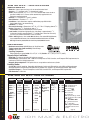
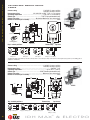
LCN 4040 SERIES
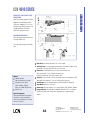
The 4040 SUPER SMOOTHEE® is
CLOSER MOUNTS
HINGE (PULL SIDE) (Shown)
TOP JAMB (PUSH SIDE)
PARALLEL ARM (PUSH SIDE)
LCN’s most flexible heavy duty
closer designed for institutional
and other rugged high traffic
applications.
Ten Million Cycles
Cast Iron
Forged Steel Arm
Double Heat Treated Steel
Pinion
All Weather Fluid
Non-Handed
LCN® Fast™ Power Adjust
Fast & Accurate Installation
Standard 4040 series closer shipped with regular arm, standard plastic
clip-on cover, and self reaming and tapping screws. See 4040 Series
pages 45-47 for options.
Non-sized cylinder is adjustable for interior doors to 5’0” and exterior
doors to 4’0”.
Closer mounts hinge side, top jamb, and parallel arm w/PA Shoe on
either right or left swinging doors.
Closers to meet ADA requirements. See 4040 Series page 48.
Standard or optional custom powder coat finish.
Optional plated finish on cover, arm, and fasteners.
Optional SRI primer for installations in corrosive conditions.
UL and cUL listed for self-closing doors without hold-open.
Tested and certified under ANSI Standard A156.4, grade one.
Available
Not available
UL & cUL Listed
For XP See Page 40
The 4040 Series includes the
LCN FAST™ Power Adjust,
a revolutionary visual indicator
for Spring Power Adjustment.
®
Closer available with less than 5.0 lbs. opening force on 36" door.
**Maximum opening/hold-open point with standard template.
*** Advanced Variable Backcheck
39
LCN CLOSERS
121 W. RAILROAD AVE.
P.O. BOX 100
PRINCETON, IL, USA 61356-0100
PHONE 800-526-2400
FAX 800-248-1460
www.lcn.ingersollrand.com
3/10
LCN 4040 SERIES
4040XP
The 4040XP is LCN’s most durable heavy duty closer
designed for the most demanding, high use and
abuse applications.
4040XP
Non-sized cylinder is adjustable for interior doors to 5’0” and
exterior doors to 4’0”.
Closer mounts parallel arm (EDA arm) on either right or left
swinging doors.
Optional hinge side and top jamb mount with optional regular arm.
Closers to meet ADA requirements. See 4040XP Series page 49.
Standard or optional custom powder coat finish.
Optional plated finish on metal cover, arm and fasteners.
Optional SRI primer for installations in corrosive conditions is
available with powder coat only.
UL and cUL listed for self-closing doors without hold-open.
4040XP can be used with all 4041 accessories. See pages 4547 for options.
44% increased bearing load capacity
Strongest pinion ever- at 3/4” journal diameter
Widest bearing ever- at 5/8”
Stronger pinion teeth
New V-shield™ seal with longer life
XP = eXtra Protection in real world applications
Cast Iron
Forged Steel Arm
Double Heat Treated Steel Pinion
All Weather Fluid
Non-Handed
LCN® Fast™ Power Adjust
Fast & Accurate Installation
UL & cUL Listed
Tested and certified under ANSI Standard A156.4,
grade one
The 4040 Series includes the
LCN FAST™ Power Adjust,
a revolutionary visual indicator
for Spring Power Adjustment.
®
Available
Not available
Closer available with less than 5.0 lbs. opening force on 36" door.
**Maximum opening/hold-open point with standard template.
*** Advanced Variable Backcheck
40
LCN CLOSERS
121 W. RAILROAD AVE.
P.O. BOX 100
PRINCETON, IL, USA 61356-0100
PHONE 800-526-2400
FAX 800-248-1460
www.lcn.ingersollrand.com
3/10
LCN 4040 SERIES
HINGE (PULL) SIDE
MOUNTING
MAXIMUM OPENING
Templating allows up to 120°.
Hold-open points 90° up to 120° with
hold-open arm.
Butt Hinges should not exceed 5” (127 mm) in width.
Auxiliary Stop is recommended at hold-open point or where a door
cannot swing beyond 120°.
Reveal should not exceed 3/4” (19 mm) for regular arm or hold-open arm.
Options
4040XP cylinder
4041 Delayed action cylinder.
Hold-open arm.
Metal cover.
Special Templates
Customized installation templates
or products may be available to
solve unusual applications.
Contact LCN for assistance.
Top Rail less than 3 3/4” (95 mm) requires PLATE, 4040-18.
Plate requires 2” (51 mm) minimum.
Clearance of 2 3/8” (60 mm) behind door required for 90° installation.
Delayed Action (not available on 4040XP) Add suffix “DEL” to selected
cylinder (eg. 4041 DEL). Delays closing from 120° to 70°.
Delay time adjustable up to approximately 1 minute.
41
LCN CLOSERS
121 W. RAILROAD AVE.
P.O. BOX 100
PRINCETON, IL, USA 61356-0100
PHONE 800-526-2400
FAX 800-248-1460
www.lcn.ingersollrand.com
3/10
LCN 4040 SERIES
TOP JAMB (PUSH SIDE)
MOUNTING
MAXIMUM OPENING
Templating allows up to 120°.
Hold-open points 85° up to 120° with
hold-open arm.
Butt Hinges should not exceed 5” (127 mm) in width.
Auxiliary Stop is recommended at hold-open point or where the
door cannot swing 120°.
Reveal of 2 9/16” (65 mm) allows 120° opening for REGULAR ARM or
standard HOLD-OPEN ARM. 4 13/16” (122 mm) allows up to 120°
opening with LONG ARM where standard rod and shoe is replaced
with optional LONG ROD AND SHOE 4040-79LR. Use H-LONG ARM
with LONG HEAD AND TUBE, 4040-78HL for hold-open. 8” (203 mm)
allows up to 120° opening with EXTRA LONG ARM where standard
rod and shoe is replaced with optional EXTRA LONG ROD AND SHOE,
4040-79ELR.
Top Rail requires 1 1/4" (32 mm) minimum.
2 1/4" (57 mm) minimum with closer on PLATE, 4040-18TJ.
3" (76 mm) minimum with closer on PLATE, 4040-18G.
Head Frame less than 3 1/2” (89 mm) requires PLATE, 4040-18TJ.
With flush ceiling, use PLATE, 4040-18G.
Either plate requires 1 3/4” (44 mm) minimum.
Delayed Action (not available on 4040XP) Add suffix “DEL” to
selected cylinder (eg. 4041 DEL). Delays closing from 120° to 80°.
Delay time adjustable up to approximately 1 minute.
42
Options
4040XP cylinder
4041Delayed action cylinder.
Long arm, extra long arm, holdopen arm, long hold-open arm.
Metal cover.
Special Templates
Customized installation templates
or products may be available to
solve unusual applications.
Contact LCN for assistance.
LCN CLOSERS
121 W. RAILROAD AVE.
P.O. BOX 100
PRINCETON, IL, USA 61356-0100
PHONE 800-526-2400
FAX 800-248-1460
www.lcn.ingersollrand.com
3/10
LCN 4040 SERIES
PARALLEL ARM (PUSH SIDE)
MOUNTING
Optional mounting requires PA SHOE,
4040-62PA for REGULAR or HOLDOPEN arms. Add prefix "P" to closer
description (eg. P4041). P4041 closer
includes 4040-201 FIFTH HOLE
SPACER to support PA SHOE.
MAXIMUM OPENING
180° opening/hold-open points with
all except CUSH arms.
110° opening/hold-open with CUSH
arms.
Butt Hinges should not exceed 5” (127 mm) in width.
Auxiliary Stop is recommended at hold-open point, where the door cannot
swing 180°, or where CUSH-N-STOP arm is not used.
Clearance for 4040-62PA shoe is 4” (102 mm) from door face.
EDA shoe projects 5 1/2” (140 mm) from door face.
Options
4040XP cylinder
4041Delayed action cylinder.
Hold-open, EDA, HEDA,
CUSH, HCUSH, SPRING
CUSH, or SPRING HCUSH arm.
Metal cover.
Special Templates
Customized installation templates
or products may be available to
solve unusual applications. Contact
LCN for assistance.
CUSH shoe projects 6” (152 mm) from door face.
Top Rail less than 5 3/8” (137 mm) measured from the stop requires PLATE,
4040-18PA. Plate requires 2” (51 mm) minimum from the stop.
Head Frame flush or rabetted requires PA SHOE ADAPTER, 4040-419.
Stop Width minimum 1” (25 mm).
Blade Stop clearance requires 1/2" (13mm) BLADE STOP SPACER, 4040-61.
Delayed Action (not available on 4040XP) Add suffix “DEL” to selected
cylinder (eg. P4041 DEL). Delays time adjustable up to approximately 1
minute.
43
LCN CLOSERS
121 W. RAILROAD AVE.
P.O. BOX 100
PRINCETON, IL, USA 61356-0100
PHONE 800-526-2400
FAX 800-248-1460
www.lcn.ingersollrand.com
3/10
LCN 4040 SERIES
Mounting details are the same as
4040 Series REGULAR or HOLDOPEN except as listed below.
4040 Series closers ordered with
EDA or CUSH arms include 4040201 FIFTH HOLE SPACER to
support the shoe.
4040 SERIES EDA MOUNT
MAXIMUM OPENING
EDA arm can be templated for
points at: 110°,
A = 6 3/8” (162 mm)
B = 7 3/4” (197 mm)
or 180°.
A = 2 7/8” (73 mm)
B = 4 1/4” (108 mm)
Hold-open points up to maximum
opening with HEDA arm.
4040 SERIES CUSH MOUNT
CUSH arms can be templated for
opening/hold-open point at:
85°,
A = 7 15/16” (202 mm)
B = 9 1/8” (232 mm)
90°,
A = 7 3/16” (183 mm)
B = 8 1/2” (216 mm)
100°,
A = 6 1/16” (154 mm)
B = 7 1/4” (184 mm)
or 110°.
A = 5 1/16” (129 mm)
B = 6 3/8” (162 mm)
Clearance for 4040-62EDA is 5 1/2” (140 mm) from door
face. 6” (152 mm) for CUSH.
Head Frame flush or rabetted requires CUSH FLUSH
PANEL ADAPTER, 4040-419.
CUSH ARM requires SHOE SUPPORT, 4040-30 for fifth
screw anchorage for narrow frames.
Delayed Action (not available on 4040XP) Add suffix
“DEL” to selected cylinder (eg. 4041 DEL). Delays closing
from maximum opening to; 115˚ with 180˚ template.
95˚ with 110˚ template. 85˚ with 100˚ template.
75˚ with 90˚ template.
Delay time adjustable up to approximately 1 minute.
44
Spring Cush dead stop points
are approximately 5˚ more than
templated stop point. Hold open
at templated stop points.
LCN CLOSERS
121 W. RAILROAD AVE.
P.O. BOX 100
PRINCETON, IL, USA 61356-0100
PHONE 800-526-2400
FAX 800-248-1460
www.lcn.ingersollrand.com
3/10
LCN 4040 SERIES
CYLINDERS
3071XP
CYLINDER, 4041-3071
Standard, non-handed cast iron cylinder assembly.
CYLINDER, 4040XP-3071
Heavy duty, non-handed cast iron cylinder assembly.
3071
COVERS
COVER, 4040-72
Standard, non-handed plastic clip-on cover.
METAL COVER, 4040-72MC
Optional, handed cover. Required for plated finishes and custom
powder coat finishes.
72
72MC
62PA
ARMS
REGULAR ARM, 4040-3077
Non-handed arm mounts pull side or top jamb with shallow reveal.
P4041 closer includes PA SHOE, 4040-62PA required for parallel arm
mounting.
PA SHOE, 4040-62PA
Required for parallel arm mounting.
LONG ARM, 4040-3077L
Optional non-handed arm includes LONG ROD AND SHOE, 4040-79LR
for top jamb mount.
EXTRA LONG ARM, 4040-3077ELR
Optional non-handed arm includes EXTRA LONG ROD AND SHOE,
4040-79ELR for top jamb mount with deep reveal.
HOLD-OPEN ARM, 4040-3049
Optional, non-handed arm mounts pull side or top jamb with shallow
reveal, hold-open adjustable shoe. P4041 closer includes 4040-62PA
shoe required for parallel arm mounting.
LONG HOLD-OPEN ARM, 4040-3049L
Optional non-handed arm includes LONG HEAD AND TUBE, 40403048L for top jamb mount.
EXTRA DUTY ARM, 4040-3077EDA
Non-handed parallel arm features forged, solid steel main and
forearm for potentially abusive installations.
HOLD-OPEN EXTRA DUTY ARM, 4040-3049EDA
Optional handed arm provides hold-open function, adjustable at the
shoe.
EDA ARM w/THICK HUB SHOE, 4040-3077EDAG
Optional for blade stop clearance, requires special templating.
HEDA ARM w/THICK HUB SHOE, 4040-3049EDAG
Optional for blade stop clearance, requires special templating.
45
79LR
79ELR
3077
3049L
3049
3077EDA
3049EDA
62G
LCN CLOSERS
121 W. RAILROAD AVE.
P.O. BOX 100
PRINCETON, IL, USA 61356-0100
PHONE 800-526-2400
FAX 800-248-1460
www.lcn.ingersollrand.com
3/10
LCN 4040 SERIES
ARMS cont.
3077CNS
CUSH-N-STOP® ARM, 4040-3077CNS
Optional, non-handed parallel arm features solid forged steel
main arm and forearm with stop in soffit shoe.
HCUSH ARM, 4040-3049CNS
Provides hold-open function with templated stop/hold-open
points. Handle controls hold-open function.
3049CNS
SPRING CUSH ARM, 4040-3077SCNS
Optional, non-handed parallel arm for abusive applications
features solid forged steel main arm and forearm with spring
loaded stop in the soffit shoe.
3077SCNS
SPRING HCUSH ARM, 4040-3049SCNS
Optional, non-handed parallel arm for abusive applications
features solid forged steel main arm and forearm with spring
loaded stop in the soffit shoe. Handle controls hold-open
function.
3049SCNS
INSTALLATION ACCESSORIES
PLATE, 4040-18
Required for hinge side mount where top rail is less than
3 3/4” (95 mm). Plate requires minimum 2” (51 mm) minimum top
rail.
PLATE, 4040-18G
Locates top jamb mounted closer flush with top of head frame
face in flush ceiling condition. Plate requires 1 3/4” (44 mm)
minimum head frame.
18
PLATE, 4040-18TJ
Centers top jamb mounted closer vertically on head frame
where face is less than 3 1/2” (89 mm). Plate requires 1 3/4”
(44 mm) minimum head frame.
PLATE, 4040-18PA
Required for parallel arm mounting where top rail is less than
5 1/2” (140 mm), measured from the stop. Plate requires
2” (51 mm) minimum top rail.
18TJ
18G
18PA
46
LCN CLOSERS
121 W. RAILROAD AVE.
P.O. BOX 100
PRINCETON, IL, USA 61356-0100
PHONE 800-526-2400
FAX 800-248-1460
www.lcn.ingersollrand.com
3/10
LCN 4040 SERIES
INSTALLATION ACCESSORIES cont.
CUSH SHOE SUPPORT, 4040-30 provides anchorage for fifth
screw used with CUSH arms, where reveal is less than
3 1/16” (78 mm).
30
61
BLADE STOP SPACER, 4040-61 required to lower parallel arm
shoe to clear 1/2” (13 mm) blade stop.
61
PA FLUSH PANEL ADAPTER, 4040-419 provides horizontal
mounting surface for PA or CUSH shoe on single rabetted or flush
frame.
AUXILIARY SHOE, 4040-62A requires a top rail of 7”
(178 mm). Optional shoe replaces -62PA for parallel arm mounting
of regular arm with overhead holder/stop.
419
62A
47
LCN CLOSERS
121 W. RAILROAD AVE.
P.O. BOX 100
PRINCETON, IL, USA 61356-0100
PHONE 800-526-2400
FAX 800-248-1460
www.lcn.ingersollrand.com
3/10
LCN 4040 SERIES
TABLE OF SIZES
4041 cylinders are adjustable from size 1 through size 6 and is shipped set to
size 3.
Closing power of 4040 series closers may be adjusted 50%.
Indicates recommended range of door width for closer size.
EXTERIOR (and VESTIBULE) DOOR WIDTH
30"
762mm
24"
610mm
size 3
size 5
1. SELECT FINISH.
Standard Powder Coat __________
Aluminum, Dark Bronze , Statuary,
Light Bronze, Black, Brass.
Closer will be shipped with:
- STANDARD CLIP-ON COVER,
- REGULAR ARM,
- SELF-REAMING and TAPPING SCREWS,
unless options listed below are selected.
36"
42"
48"
914mm 1067mm1219mm
size 4
HOW-TO-ORDER
4041 SERIES CLOSERS
size 6
*4041
CLOSER OPTIONS
Minimum
Door
Width
INTERIOR DOOR WIDTH
34"
38"
864mm 965mm
24"
610mm
size 2
size 3
48"
54"
60"
1219mm 1372mm 1524mm
size 4
size 5
size 6
*4041
Minimum
Door
Width
* Adjustable Size 1 thru 6
REDUCED OPENING FORCE 4040 SERIES CLOSERS
CAUTION ! Any manual door closer, including those certified by BHMA to
conform to ANSI Standard A156.4, that is selected, installed and adjusted
based on ADA or other reduced opening force requirements may not provide
sufficient power to reliably close and latch a door.
Refer to POWER OPERATORS section for information on systems that meet
reduced opening force requirements without effecting closing power.
DOOR WIDTH
36"
42"
48"
8.5* lbs.
4041
4041
4041
5.0* lbs.
4041
4041
4041
* Maximum opening force
48
CYLINDER
Delayed Action (DEL)
COVER
Metal (specify right or left hand) (MC)
FINISH
Custom Powder Coat (RAL) ___________
(handed metal cover required)
Plated Finish, US ______________
(handed metal cover required)
SRI primer
ARM
Regular w/62PA (Rw/PA)
Regular w/62A (R/62A)
Long (LONG)
Extra Long (XLONG)
Hold-Open (H)
Hold-Open w/62PA (Hw/PA)
Long Hold-Open (HLONG)
EDA (optional -62G)
HEDA (specify right or left hand, optional-62G)
Cush-N-Stop (CUSH)
HCush-N-Stop (HCUSH)
Spring Cush (SCUSH)
Spring HCush (SHCUSH)
OPTIONAL SCREW PACKS
TB* w/Self-Reaming and Tapping (TBSRT)
Wood & Machine Screw (WMS)
TB*, Wood & Machine Screw (TBWMS)
TORX Machine Screw (TORX)
TB* & TORX Machine Screw (TBTRX)
* Specify door thickness if other than 1 3/4”.
INSTALLATION ACCESSORIES
Plate, 4040-18
Plate, 4040-18TJ
Plate, 4040-18G
Plate, 4040-18PA
CUSH Shoe Support, 4040-30
Blade Stop Spacer, 4040-61
Auxiliary Shoe, 4040-62A
PA Flush Panel Adapter, 4040-419
SPECIAL TEMPLATE
ST- ________
LCN CLOSERS
121 W. RAILROAD AVE.
P.O. BOX 100
PRINCETON, IL, USA 61356-0100
PHONE 800-526-2400
FAX 800-248-1460
www.lcn.ingersollrand.com
3/10
LCN 4040 SERIES
TABLE OF SIZES
4040XP cylinders are adjustable from size 1 through size 6 and is shipped set
to size 3.
Closing power of 4040 series closers may be adjusted 50%.
Indicates recommended range of door width for closer size.
EXTERIOR (and VESTIBULE) DOOR WIDTH
30"
762mm
24"
610mm
size 3
size 5
1. SELECT FINISH.
Standard Powder Coat __________
Aluminum, Dark Bronze , Statuary,
Light Bronze, Black, Brass.
Closer will be shipped with:
- STANDARD CLIP-ON COVER,
- SPECIFY ARM WHEN ORDERING,
- SELF-REAMING and TAPPING SCREWS,
unless options listed below are selected.
36"
42"
48"
914mm 1067mm1219mm
size 4
HOW-TO-ORDER
4040XP SERIES CLOSERS
size 6
*4040XP
CLOSER OPTIONS
Minimum
Door
Width
INTERIOR DOOR WIDTH
34"
38"
864mm 965mm
24"
610mm
size 2
size 3
48"
54"
60"
1219mm 1372mm 1524mm
size 4
size 5
size 6
*4040XP
Minimum
Door
Width
* Adjustable Size 1 thru 6
REDUCED OPENING FORCE 4040 SERIES CLOSERS
CAUTION ! Any manual door closer, including those certified by BHMA to
conform to ANSI Standard A156.4, that is selected, installed and adjusted
based on ADA or other reduced opening force requirements may not provide
sufficient power to reliably close and latch a door.
Refer to POWER OPERATORS section for information on systems that meet
reduced opening force requirements without effecting closing power.
DOOR WIDTH
36"
42"
48"
8.5* lbs.
4041
4041
4041
5.0* lbs.
4041
4041
4041
* Maximum opening force
49
COVER
Metal (specify right or left hand) (MC)
FINISH
Custom Powder Coat (RAL) ___________
(handed metal cover required)
Plated Finish, US ______________
(handed metal cover required)
SRI primer
ARM
Regular (Rw)
Regular w/62PA (Rw/PA)
Regular w/62A (R/62A)
Long (LONG)
Extra Long (XLONG)
Hold-Open (H)
Hold-Open w/62PA (Hw/PA)
Long Hold-Open (HLONG)
EDA (-62G)
HEDA (specify right or left hand, optional-62G)
Cush-N-Stop (CUSH)
HCush-N-Stop (HCUSH)
Spring Cush (SCUSH)
Spring HCush (SHCUSH)
OPTIONAL SCREW PACKS
TB* w/Self-Reaming and Tapping (TBSRT)
Wood & Machine Screw (WMS)
TB*, Wood & Machine Screw (TBWMS)
TORX Machine Screw (TORX)
TB* & TORX Machine Screw (TBTRX)
* Specify door thickness if other than 1 3/4”.
INSTALLATION ACCESSORIES
Plate, 4040-18
Plate, 4040-18TJ
Plate, 4040-18G
Plate, 4040-18PA
CUSH Shoe Support, 4040-30
Blade Stop Spacer, 4040-61
Auxiliary Shoe, 4040-62A
PA Flush Panel Adapter, 4040-419
SPECIAL TEMPLATE
ST- ________
LCN CLOSERS
121 W. RAILROAD AVE.
P.O. BOX 100
PRINCETON, IL, USA 61356-0100
PHONE 800-526-2400
FAX 800-248-1460
www.lcn.ingersollrand.com
3/10
IDH MAX® &
ELECTROMECHANICAL LOCKS
IDH MAX® & ELECTROMECHANICAL LOCKS
IDH MAX® – INTRODUCTION
IDH MAX® – FEATURES
TABLE OF CONTENTS
Page
IDH MAX® introduction ........................................................2
IDH MAX® features ..............................................................2
IDH Max® and IDH Max® 1300 comparison chart ................3
HM, KM, HW & KW options..................................................3
40HM IDH MAX® specifications, how-to-order ....................4
40HM IDH MAX® functions ..................................................5
93KM IDH MAX® specifications, how-to-order ....................6
93KM IDH MAX® functions ..................................................7
40HW/8KW/9KW electrified lock introduction ......................7
40HW electrified specification ..............................................7
40HW electrified how-to-order..............................................8
Page
40HW electrified functions ..............................................8-9
8KW/9KW electrified specification ....................................10
8KW/9KW electrified how-to-order ..................................10
8KW/9KW electrified functions ........................................10
Trim variations ..................................................................11
Electrified accessories ................................................12,13
Terminology ......................................................................13
1W electric switch lock introduction ..................................14
Optional boxes ..................................................................14
1W electric switch lock how-to-order ................................14
1W electric switch locks................................................15-19
IDH MAX® – INTRODUCTION
The IIDH MAX® from Stanley Security Solutions offers convenience and efficiency for your electrified lock applications. Instead of
installing reader devices, installing electrified strikes, installing door contacts and installing request-to-exit devices, you can now
install the IDH MAX® in cylindrical or mortise lock applications. With IDH MAX® all of the formerly separate equipment needed to
control access are self-contained in a single installation. The complexity of multiple wire runs is drastically reduced.
You can let Stanley Security Solutions show you how to MAXimize your access control system with the IDH MAX®! For the name
and location of your local office, visit our web site at www.stanleysecuritysolutions.com. IDH MAX® and W series locks (with the
exception of the IDH Max® 1300) are compatible with Stanley’s NT500 and B.A.S.I.S. Acess Control Systems.
IDH MAX® – FEATURES
Mortise Features (continued)
• Twist off lever spindle design protect internal lock parts from
• Includes latch and door position indicator, RQE switch.
damage and failure.
• The 1300 option eliminates the need for a RIM (reader
• Oil impregnated stainless steel 3/4" anti-friction latchbolt
interface module) which is embedded behind the escutcheon
reduces door closing force and wear.
• Requires only one 4 conductor wire run
• Reduces number of components installed and visible at the
Cylindrical Features
door (PIR, RQE push buttons and door contacts)
• Non-handed levers allow for ease of installation
• Installation time is reduced
•
Lock chassis meets the requirements as listed in the ANSI/
• The RQE switch senses the inside lever/knob rotation.
BHMA
A156.2, standard for Series 4000 Grade 1 locks
• All of the door components are housed in one
•
UL
listed
for GYQS Electrically controlled single point licks or
manufacturer's hardware
latches
for
use on 3 hr, A label single doors (4' x 10') GYJB.
• With the elimination of components, only the lockset is
The
listing
applies
for both U.S. and Canadian applications
visible at the door
•
Request-to-exit
sensor
positioned inside lock trim
• The reader is integrated into the lockset escutcheon
•
The
ISC
(Intelligent
System
Controller) is embedded behind
• Available in magnetic stripe and proximity readers
the
escutcheon
secured
and
out of site
• Available in all popular lever/knob styles and finishes
•
Request-to-exit
and
door
contact
sensors are standard in
• Operates with BEST interchangeable core as a
IDH
MAX
cylindrical
locks
mechanical override
• Integrates with many manufacturer's on-line EAC equipment
IDH Max® Features
Magnetic Stripe Electronic Lock Features
Mortise Features
• Durable material has teflon-like characteristics for increased
life and wear resistance
• Variable read rate allows for easy usage
• Lock case meets the requirements as listed in the ANSI/
BHMA A156.13 standard for Series 1000, Grade 1
Operational and Grade 2 Security locks
Proximity Card Reader Features
• UL listed for GYQS Electrically controlled single point locks or
• HID and Motorola/Indala proximity cards supported
latches for use on 3 hr, A label doors (4' x 10' ). The listing
• UL listed for GYQS Electrically controlled single point locks
applies for both U.S. and Canadian applications
or latches.
• Door contact, request-to-exit, and latch status sensors
• Usable in all environmental/exterior applications.
positioned inside lock case
• The 1300 option eliminates the need for a RIM (reader
1300 Option Features
interface module) which is embedded behind the escutcheon
• Eliminates need for small panel interface module
• The door contact magnet is installed behind the strike and
• Eliminates reader interface board
out of site (except when deadbolt option is ordered)
• Incorporates 3 modules into a single electronics board inside
• All sensors are standard in IDH Max mortise locks
IDH Max escutcheon trim
• The heavy duty design of the mortise lock makes easy field
• Connects directly to ACP via 2 wire RS485 connection
maintenance and reduces risk of part failure
2
IDH MAX® & ELECTRO
*
**
IDH MAX®
1. Prep door for IDH MAX®
2. Run single 4 conductor wire for IDH MAX®
3. Install IDH MAX®
4. Install electrified hinge
5. Mount control panel
IDH MAX® 1300
1. Prep door for IDH MAX®
2. Run single 4 conductor wire for IDH MAX® 1300
3. Install IDH MAX® 1300 which includes Intelligent System
4. Install electrified hinge
IDH MAX® COMPARISON CHART
IDH MAX® & IDH MAX® 1300 COMPARISON CHART
** Operates with B.A.S.I.S. control panels only.
HM, KM, HW & KW – OPTIONS
AL– Besides complying with a wide variety of accessibility codes and ordinances, lever handles are available with a special abrasive
feature. Abrasive strip on the lever immediately identifies warnings on doors to hazardous areas for the blind.
BRK– When excessive force (approx. 300 inch lbs.) is applied to #4, #6 keyed knobs, they “breakaway” and spin freely, thus allowing
entrance only by key. Simple part replacement returns lock to functional usage.
IDH– The integrated Door Hardware groups three components into one hardware package. 1. Door monitoring switch (normally
closed) 2. Request-to-Exit switch (normally open) 3. Electrically controlled locking mechanism.
KNL– Knurl feature is available only on #6 knobs. The knurling is machined into the outer edge of the knob. The knurled feature
can be used for blind, safety, or accessibility applications.
LL– Lead lined feature can be used to protect against X-rays. Since the majority of lead lined doors contain the lead in the
surface of the door, the knob lockset provide lead lining for the holes cut in the door when preparing the door for the trim.
LM– The Lost Motion feature allows the lever handle to move 45 degrees from parallel to the horizontal plane without engaging the
latchbolt assembly. When the lockset is in the locked mode, this feature makes over-torque or over-lever-age abuse more difficult
to achieve.
SH– Security head provided for all exposed screws.
RQE– Cylindrical or Mortise locksets can be supplied with a request-to-exit switch. A normally open switch provides momentary
switch closure when the inside lever/knob is rotated.
HM, KM, HW KW – OPTIONS
* Operates with any control panel hardware, including B.A.S.I.S.
control panels.
TAC– Grooves are machined into knobs to improve grip or to be used as a warning in hazardous areas. This option can be used for
blind, safety or accessibility applications.
Thick door– Specify thickness if other than 1 3⁄4" .
TL– Tactile levers may be used in areas where improved grip is required or as a warning in hazardous or Safety First areas. Grooves
are machined into the back of the hand grasp portion of the lever to improve grip and/or provide a sensory warning. This option
can be used for blind, safety, or accessibility applications.
1300– Integrated BAS1300/LNL1300 reader electronics board or (ISC) Intelligent System Controller is embedded behind the
escutcheon secured and out of site. Functions with B.A.S.I.S./Mercury on-line equipment only.
MECHANICAL LOCKS
3
40HM IDH MAX® SPECIFICATIONS
40HM IDH MAX® – SPECIFICATIONS
MECHANICAL
Case— Heavy wrought steel, 5 7⁄8" H x 4 1⁄4" D x 1" W steel parts are zinc
dichromate plated for corrosion protection.
Faceplate— Brass or bronze, 1 1⁄4" x 8" x 7⁄32" . Armored. Adjustable from flat
to beveled 1⁄8" - 2" .
Strike— Brass, bronze or Stainless Steel, 4 7⁄8" x 1 1⁄4" x 3⁄32". Fits standard
door frame cut out as specified in ANSI A115.1.Correct strike automatically
supplied with unit. Strike box supplied standard.
Door thickness— For doors 1 3⁄4" – 4" thick.
Installation— Lock requires modified door prep to mount the trim. Faceplate
dimensions fit standard door preparation as specified in ANSI A115.1,.
Lockset is reversible for hand of door.
Latchbolt— Stainless steel, 3⁄4" throw with anti-friction latch.
Deadbolt— Solid stainless steel, 1" throw.
Auxiliary bolt— Stainless steel.
Die cast trim housing—Dimensions: 10 3⁄8" H x 3 1⁄4" W x 1" D sloping down to 3⁄4".
Knobs— Diameter: 2 1⁄8" Projection on door: 2 7⁄8"
#4, #6 knobs: Material machined from brass or bronze.
Lever handle— Brass, bronze or stainless steel. (Lever #3, #14 and #15
conform to California Titles 19 and 24.)
Mounting— Knob and lever attached with hardened set screw on inside knob or
45HM IDH MAX® Mortise
inside lever.
Finish— 605-bright brass, clear coated; 606-satin brass, clear coated; 611-bright bronze, clear coated; 612-satin bronze, clear
coated; 613-oxidized satin bronze, oil rubbed; 625-bright chromium plated; 626-satin chromium plated; 629-bright stainless
steel; 630-satin stainless steel; 690-dark bronze.
ELECTRONIC
Maximum current draw: 1.1 Amp for 50 milliseconds
Typical current draw (hold condition): 650 milliAmps
Voltage: 10.2 to 13.2 V (DC only)
Operating Temperature: Minimum/Maximum range Inside: 70˚± 4˚F (21˚± 2˚C) Outside: -31˚F (-35˚C) to +151˚F (+66˚C)
Magnetic Stripe Card Reader:
Read Rate: 5 inches per second to 50 inches per second.
Card thickness: ISO standard .030" ± .003 thick.
Compliance to FCC, Canadian, and European EMC requirements; for interference FCC Class A digital apparatus.
Magnetic Stripe adaptation: Trim option that can accept other manufacturers cylinder.
Proximity Reader:
HOW TO ORDER
ANSI/BHMA A156.25 compliant. Compatible with Motorola / Indala and HID proximity cards. ABA and Wiegand output.
Weatherproof bezel and gasket provide protection for outdoor use. (Usable in all environmental/exterior applications)
Card Read Range: 0 – 3 inches. Compliance to US FCC, Canadian FCC, and European EMC requirements
ESD Protection:15 Kilo Volt
40HM IDH MAX® – HOW TO ORDER
45HM
Series
7
Core
Housing
45HM–
0– Keyless
IDH Max™
or less
cylinder,
7– 7 pin
housing
ONLY
DEU
Function
DEL– electrically
locked
DEU– electrically
unlocked
NXEL– electrically
locked
NXEU– electrically
unlocked
TDEL– electrically
locked
TDEU– electrically
unlocked
LEL– electrically
locked
LEU– electrically
unlocked
14
Lever/Knob
Style
Levers
3– solid tube return
12– solid tube
14– curved return
15– curved angle
return
16– curved no return
17– gullwing no
return
Knobs
4– round
MS
Trim
Style
MS– magnetic
stripe
PM– proximity
Motorola
PH– proximity
HID
MSA– other
cylinder
PHA– other
cylinder
PMA– other
cylinder
626
RH
Finishes Handing
†
605
611
613
619
626
606
612
618
625
690
(page 5)
(page 11)
(page 11)
**Must specify key mark and number of keys or designate L/C for less core. †See H Series catalog for details.
4
RH
RHRB
LH
LHRB
KNL
Options†
SH – security head screws
TAC – tactile lever
Thick
Door – specify thickness if
other than 1 3/4"
7/8" LTC– flat lip strike
1300 – B.A.S.I.S. direct
connect
(page 3)
IDH MAX® & ELECTRO
Function
DEL–Locked
Fail Safe
Latch
Operated by
• Outside knob/lever
when power is removed
from the solenoid
• Outside key
• Inside knob/lever.
Latchbolt is
deadlocked by an
auxiliary latch
Outside Knob/Lever
Unlocked by
Locked by
Applying power to the
solenoid; remains locked
while power is on.
Inside Knob/Lever
Locked by
Unlocked by
Removing power from the solenoid Cannot be locked
Always unlocked
Powered by 12V DC. temperature control module is not needed.
DEU–Unlocked
Fail Secure
• Outside knob/lever
when power is applied
to the solenoid
• Outside key
• Inside knob/lever.
Latchbolt is
deadlocked by an
auxiliary latch
Removing power from the
solenoid
Applying power to the solenoid;
remains unlocked while power is
on.
Cannot be locked
Always unlocked
• Outside knob/lever
Applying power to solenoid; Removing power from the solenoid Cannot be locked
when power is removed remains locked while power
from the solenoid
is on.
• Inside knob/lever.
Latchbolt is
deadlocked by an
auxiliary latch
Always unlocked
Powered by 12V DC. temperature control module is not needed.
NXEL–Locked
Fail Safe
40HM IDH MAX® – FUNCTIONS
40HM IDH MAX® – FUNCTIONS
Powered by 12V DC. temperature control module is not needed.
NXEU–Unlocked
Fail Secure
• Outside knob/lever
when power is applied
to the solenoid
• Inside knob/lever.
Latchbolt is
deadlocked by an
auxiliary latch
Removing power from the
solenoid
Applying power to the solenoid;
remains unlocked while power is
on.
Cannot be locked
Always unlocked
Cannot be locked
Always unlocked
Cannot be locked
Always unlocked
Removing power from the solenoid Cannot be locked
Deadbolt retracted by:
• Inside thumb turn
• Inside knob/lever retracts the
deadbolt and latchbolt
simultaneously
• Outside lever when power is
removed
Always unlocked
Powered by 12V DC. temperature control module is not needed.
TDEL–Locked
Fail Safe
• Outside key
• Outside knob/lever
when power is removed
from the solenoid.
• Inside knob/lever.
Latchbolt is
deadlocked by an
auxiliary latch
Applying power to the
solenoid; remains locked
while power is on.
Deadbolt operated by:
• Outside key
• Inside thumb turn
Removing power from the
solenoid
Deadbolt and Latchbolt
retracted simultaneously by:
• Inside knob/lever
• Outside knob/lever when
power is removed
Powered by 12V DC. temperature control module is not needed.
TDEU–Unlocked
Fail Secure
• Outside key
• Outside knob/lever
when power is applied
to the solenoid
• Inside knob/lever.
Latchbolt is
deadlocked by an
auxiliary latch
Removing power from the
solenoid
Applying power to the solenoid;
remains locked while power is on.
Deadbolt operated by:
• Outside key
• Inside thumb turn
Deadbolt and Latchbolt
retracted simultaneously by:
• Inside knob/lever
• Outside knob/lever when
power is applied
Powered by 12V DC. temperature control module is not needed.
LEL–Locked
Fail Safe
• Outside knob/lever
when power is removed
from the solenoid
• Inside knob/lever.
Latchbolt is
deadlocked by an
auxiliary latch
Applying power to the
solenoid; remains locked
while power is on.
Deadbolt extended by:
Inside thumb turn
Powered by 12V DC. temperature control module is not needed.
LEU–Unlocked
Fail Secure
• Outside knob/lever
when power is applied
to the solenoid
• Inside knob/lever.
Latchbolt is
deadlocked by an
auxiliary latch
Removing power from
the solenoid
Deadbolt extended by:
Inside thumb turn
Applying power to the solenoid;
remains locked while power is on.
Cannot be locked
Always unlocked
Deadbolt retracted by:
• Inside thumb turn
• Inside knob/lever retracts the
deadbolt and latchbolt
simultaneously
• Outside knob/lever when power
is applied
Powered by 12V DC. temperature control module is not needed.
MECHANICAL LOCKS
5
9KM IDH MAX® – SPECIFICATIONS
9KM IDH MAX® – SPECIFICATIONS
MECHANICAL
Materials— Internal parts are brass, zinc or corrosion-treated steel.
Chassis— 2 1⁄16" diameter to fit 2 1⁄8" diameter hole in door.
Strike— Brass or bronze, 4 7⁄8" x 1 1⁄4" x 3⁄32". Fits standard door frame cut out as
specified in ANSI A115.1. Correct strike automatically supplied with unit.
Strike box supplied standard.
Backset— 2 3⁄4" standard, 3 3⁄4" and 5" available.
Door thickness— For doors 1 3⁄4" – 2 1⁄4"
Installation— Lock dimensions requires modified door prep ANSI A156.2
Series 4000, Grade 1 to mount housing.
Latchbolt— 9⁄16" throw.
Die cast trim housing— Dimensions: 10 3⁄8" H x 3 1⁄4" W x 1" D sloping down to 3⁄4".
Knobs— Diameter: 2 1⁄8" Projection on door: 2 7⁄8"
#4, #6 knobs: Material machined from brass or bronze.
Lever handle— Made from high-quality zinc alloy. Body is approximately 1 5⁄8"
in diameter: Handle is approximately 4 3⁄4" in length (from center-line of chassis).
(Lever #14,15 conform to California Titles 19 and 24.)
Finish— 605-bright brass, clear coated; 606-satin brass, clear coated; 611-bright bronze,
clear coated; 612-satin bronze, clear coated; 613-oxidized satin bronze, oil rubbed
625-bright chromium plated; 626-satin chromium plated; 690-dark bronze.
93KM IDH MAX® Cylindrical
ELECTRONIC
Maximum current draw: 850 MilliAmps, for 50 milliseconds
Typical current draw (hold condition): 550 milliAmps
Voltage: 10.2 to 13.2 V
Operating Temperature:
Minimum/Maximum range Inside: 70˚± 4˚F (21˚± 2˚C) Outside: -31˚F (-35˚C) to +151˚F (+66˚C)
Magnetic Stripe Card Reader:
Read Rate: 5 inches per second to 50 inches per second.
Card thickness: ISO standard .030" ± .003 thick. Compliance to FCC, Canadian, and European EMC requirements; for
interference FCC Class A digital apparatus.
Magnetic Stripe adaptation: Trim option that can accept other manufacturers cylinder.
Proximity Reader:
9KM/8KM – HOW TO ORDER
ANSI/BHMA A156.25 compliant, Compatible with Motorola / Indala and HID proximity cards, ABA and Wiegand output
Weatherproof bezel and gasket provide protection for outdoor use. (Usable in all environmental/exterior applications).
Card Read Range: 0 – 3 inches. Compliance to US FCC, Canadian FCC, and European EMC requirements
ESD Protection: 15 Kilo Volt
6
9KM/8KM IDH MAX® – HOW TO ORDER
STK
7
DDEU
14
MS
Core
Function
Lever*/Knob
Trim*
Strike
Housing
Style
Style
Package
0– keyless DDEU– elecLever
Lever
MS– magnetic STK– 2 3/4"
3
stripe
14–
curved
93KM– 2 /4" 7– 7 pin
tricallyANSI
3
PM–
proximity S3– 4 7/8"
return
housing unlocked
94KM– 3 /4"
Motorola
ANSI
accepts DDEL– elec- 15– contour PH– proximity
95KM– 5"
angle
all BEST tricallyHID
Knob
return
cores
locked
3
16– curved no
83KM– 2 /4"
return
84KM– 3 3/4"
85KM– 5"
Knob
4– round
6– tulip
93KM
Series
(page 7)
(page 11)
(page 11)
626
Finishes*
605
611
613
619
626
606
612
618
625
690
TL
Options
8KM:
BRK – breakaway knob
KNL – knurled knob
TAC – tactile knob
9KM:
AL – abrasive lever
LM – lost motion
TL – tactile lever
Note: specify inside (I), outside
(O), or both (B) for AL, TL,TAC,
KNL options
Both 8KM & 9KM:
SH – security head screws
3
/4 – 3/4" throw latch
1300 – Integrated BAS1300/
LNL1300 reader electronic
board
(page 3)
* Handles and trim are made from a zinc alloy, and have been plated to be equivalent in appearance to the finishes listed.
IDH MAX® & ELECTRO
• Rotating the inside knob/lever,
• Rotating the outside knob/lever—
only when power is off,
• Turning the key in the outside
knob/lever.
Applying 12 volts DC.
The outside knob/lever
remains locked only
while power is on.
Switching off
12 volts DC
Cannot be locked
Always unlocked
Cannot be locked
Always unlocked
Powered by 12V DC. Temperature control module (TCM) is not needed.
• Rotating the inside
knob/lever,
• Rotating the outside
knob/lever—only when
power is on,
• Turning the key in the out
side knob/lever.
DDEU–Unlocked
Switching off
12 volts DC
Applying 12 volts DC.
The outside
knob/lever remains
unlocked only while
power is off.
Powered by 12V DC. Temperature control module (TCM) is not needed.
Shading indicates a
ridged lever/knob in a
non-energized state.
40HW/8KW/9KW ELECTRIFIED LOCK INTRODUCTION
The 40HW, 8KW, and 9KW electromechanical locks provide fail-safe (electrically locked) and fail-secure
(electrically unlocked) operation. They also provide a way to lock and unlock the door from a remote
location for safety, security, or convenience through an individual switch, switch lock, relay, access control
system, or other automatic control system. More importantly, these locks exhibit the same features and
meet the same standards and specifications as our mechanical 40H mortise and 8K/9K heavy duty
cylindrical locksets.
40HW ELECTRIFIED – SPECIFICATIONS
Types:
•
•
•
•
12 volts AC or DC — 0.60 amps
24 volts AC or DC — 0.45 amps
All EU functions: Electrically Unlocked (Fail Secure)
All EL functions: Electrically Locked (Fail Safe)
Approval Listings:
• UL listed for GYQS Electrically-controlled singlepoint locks or latches.
• This product has been approved by the California State Fire Marshal (CSFM)
pursuant to section 13144.1 of the California Health and Safety Code.
• Approved by the city of New York Board of Standards and Appeals under
calendar number 49-88-SA. See CSFM listing No. 4136-1175:101 for
allowable values and/or conditions fo use concerning material presented in
this document. It is subject to re-examination,revisions and possible
cancellation.
NOTE: All W-series locks require the use of a (TCM) Temperature Control Module.
A TCM and TCM connector are supplied standard with every order.
40HW Mortise
Electrically-Operated Lockset
MECHANICAL LOCKS
9KM IDH MAX®-FUNCTIONS
DDEL–Locked
Inside Knob or Lever
Unlocked by
Locked by
Outside Knob or Lever
Locked by
Unlocked by
ELECTRIFIED-INTRO
Latch
Operated by
Function
40HW ELECTRIFIED-SPECIFICATIONS
9KM IDH MAX® – FUNCTIONS
7
40HW ELECTRIFIED – HOW TO ORDER
40HW ELECTRIFIED – HOW TO ORDER
45HW
Series
7
Core
Housing
45HW:
45HW– lever
47HW– lever 0– keyless
or less
high security
cylinder,
7– 7 pin
47HW:
7– 7 pin
(accepts
5C cores
only)
NXEU
Function
12
Lever
Style
J
Trim
Style
45HW/47HW:
DEL– single key
latch, fail safe
DEU– single key
latch, fail secure
WEL– double key
latch, fail safe
WEU– double key
latch, fail secure
TDEL– single key
deadbolt, fail safe
TDEU– single key
deadbolt, fail
secure
TWEL–double key
deadbolt, fail safe
TWEU–double key
deadbolt, fail
secure
45HW only:
NXEL– keyless, latch,
fail safe
NXEU– keyless, latch,
fail secure
LEL– keyless, deadbolt,
fail safe
LEU– keyless, deadbolt,
fail secure
Levers:
3– solid tube/
return
12– solid tube/
no return
14– curved
return
15– contour/
angle return
16– curved/no
return
17– gullwing no
return
45HW:
H– 2 3/4" flat
J– wrought
M– forged
N– forged
concealed
cylinder
S– 3 1/2" flat
R– 2 3/4"
concave
(pages 8–9)
(page 11)
612
LH
Finishes Handing
†
45HW:
605 606
611 612
613 618
619 625
626 690
RH
RHRB
LH
LHRB
47HW:
626 630
47HW:
M– forged
Knobs:
4– round
RQE
Options†
AL – abrasive lever
IDH – integrated door
hardware w/RQE & DS
LL – lead lined
LS – latch status
DS – door status
RQE – request to exit
SH – security head screws
TL – tactile lever
Thick Door –
specify thickness if other
than 1 3/4"
(1 3/4" min. x 4" max)
Lock Voltage
Must specify: 24V or 12V
(page 11)
(page 3)
40HW ELECTRIFIED – FUNCTIONS
* “N” trim not available on double keyed functions. **Must specify key mark and number of keys or designate L/C for less core.
†See H Series catalog for details.
40HW ELECTRIFIED – FUNCTIONS
Latch
Outside Knob or Lever
Function
Operated by
Locked by
Unlocked by
DEL–Locked
Fail Safe
DEU–Unlocked
Fail Secure
WEL–Locked
Fail Safe
WEU–Unlocked
Fail Secure
• Outside knob/lever
when power is removed
from the solenoid
• Outside key
• Inside knob/lever.
Latchbolt is
deadlocked by an
auxiliary latch
Applying power to
solenoid; remains locked
while power is on
Removing power from
solenoid
Inside Knob or Lever
Locked by
Unlocked by
Cannot be locked
Always unlocked
Powered by 12 or 24 volts AC/DC & 0.60 or 0.45 amps, continuous duty. Temperature control module (TCM) included.
Removing power from
• Outside knob/lever
Applying power to solenoid;
Cannot be locked
Always unlocked
when power is applied
solenoid
remains unlocked while
to the solenoid
power is on
• Outside key
• Inside knob/lever.
Latchbolt is
deadlocked by an
auxiliary latch
Powered by 12 or 24 volts AC/DC & 0.60 or 0.45 amps, continuous duty. Temperature control module (TCM) included.
Applying power to
Removing power from
Applying power to the Removing power
• Inside and Outside
knob/lever when power
solenoid; remains locked
solenoid
solenoid; remains
from the solenoid
is removed from the
while power is on
locked while power is
solenoid
on
• Inside/Outside key
Latchbolt is
deadlocked by an
auxiliary latch
Temperature control module (TCM) included.
Powered by 12 or 24 volts AC/DC & 0.60 or 0.45 amps, continuous duty. Applying voltage locks inside & outside knobs/levers simultaneously.
• Inside and Outside
Removing power from
Applying power to solenoid;
Removing power from Applying power to
knob/lever when power
solenoid
remains unlocked while
solenoid
solenoid; remains
is applied to the solenoid
power is on
unlocked while
• Inside/Outside key
power is on
Latchbolt is
deadlocked by an
auxiliary latch
Powered by 12 or 24 volts AC/DC & 0.60 or 0.45 amps, continuous duty. Removing voltage locks inside & outside knobs/levers simultaneously.
Temperature control module (TCM) included.
8
IDH MAX® & ELECTRO
TDEL–Locked
Fail Safe
TDEU–Unlocked
Fail Secure
TWEL–Locked
Fail Safe
TWEU–Unlocked
Fail Secure
NXEL–Locked
Fail Safe
NXEU–Unlocked
Fail Secure
LEL–Locked
Fail Safe
LEU–Unlocked
Fail Secure
Applying power to solenoid; Removing power from solenoid
Cannot be locked
Always unlocked
• Outside key
• Outside knob/lever
remains locked while
when power is
power is on
Deadbolt and latchbolt
removed from the
retracted simultaneously by:
solenoid.
• Inside knob/lever
Deadbolt operated by: • Outside knob/lever when power is
Latchbolt is
• Outside key
removed.
deadlocked by an
auxiliary latch
• Inside thumb turn
Powered by 12 or 24 volts AC/DC & 0.60 or 0.45 amps, continuous duty. Temperature control module (TCM) included.
Removing power from
Applying power to solenoid;
• Outside key
Cannot be locked
Always unlocked
• Outside knob/lever
solenoid
remains unlocked while power is
when power is
on
applied to the
Deadbolt and latchbolt
solenoid.
Deadbolt operated by:
retracted simultaneously by:
Latchbolt is
• Outside key
• Inside knob/lever
deadlocked by an
• Inside thumb turn
• Outside knob/lever when power is
auxiliary latch
applied.
Powered by 12 or 24 volts AC/DC & 0.60 or 0.45 amps, continuous duty. Temperature control module (TCM) included.
• Outside & inside key Applying power to solenoid; Removing power from solenoid
Applying power to
Removing power
• Outside & Inside
remains locked while power
solenoid; remains
from solenoid
knob/lever when
is on
locked while power is
power is removed
on
Deadbolt operated by:
from the solenoid.
• Outside or inside key
Latchbolt is
• Outside & Inside knob/
deadlocked by an
lever when power is
auxiliary latch
Temperature control module (TCM) included.
removed from the solenoid
Powered by 12 or 24 volts AC/DC & 0.60 or 0.45 amps, continuous duty. Applying voltage locks inside & outside knobs/levers simultaneously.
Applying power to solenoid;
Removing power
• Outside & inside key Removing power from
Applying power to
remains unlocked while power is
• Outside & Inside
solenoid; remains
solenoid
from solenoid
on
knob/lever when
unlocked while power
Deadbolt operated by:
power is applied to
is on
• Outside or inside key
the solenoid.
• Outside & Inside knob/
Latchbolt is
lever when power is
deadlocked by an
auxiliary latch
applied to the solenoid
Temperature control module (TCM) included.
Powered by 12 or 24 volts AC/DC & 0.60 or 0.45 amps, continuous duty. Removing voltage locks inside & outside knobs/levers simultaneously.
40HW ELECTRIFIED – FUNCTIONS
Function
40HW ELECTRIFIED – FUNCTIONS (CONTINUED)
Latch
Outside Knob or Lever
Inside Knob or Lever
Operated by
Locked by
Unlocked by
Locked by
Unlocked by
• Outside knob/lever
Applying power to
Removing power from
Cannot be locked
Always unlocked
when power is
solenoid; remains locked
solenoid
applied to the
while power is on
solenoid
• Inside knob/lever.
Latchbolt is
deadlocked by an
auxiliary latch
Powered by 12 or 24 volts AC/DC & 0.60 or 0.45 amps, continuous duty. Temperature control module (TCM) included.
• Outside knob/lever
Removing power from
Applying power to solenoid;
Cannot be locked
Always unlocked
when power is
solenoid
remains unlocked while power is
applied to the
on
solenoid
• Inside knob/lever.
Latchbolt is
deadlocked by an
auxiliary latch
Powered by 12 or 24 volts AC/DC & 0.60 or 0.45 amps, continuous duty. Temperature control module (TCM) included.
Removing power from the solenoid Cannot be locked
Always unlocked
• Outside knob/lever Applying power to the
solenoid; remains locked
when power is
Deadbolt retracted by:
while power is on
removed from the
• Inside thumb turn
solenoid
• Inside knob/lever retracts the
• Inside knob/lever.
deadbolt and latchbolt
simultaneously
Latchbolt is
Deadbolt extended by:
•
Outside
knob/lever when power is
deadlocked by an
Inside thumb turn
removed
auxiliary latch
Powered by 12 or 24 volts AC/DC & 0.60 or 0.45 amps, continuous duty. Temperature control module (TCM) included.
• Outside knob/lever Removing power from the Applying power to the solenoid;
Cannot be locked
Always unlocked
remains unlocked while power is
when power is
solenoid
on
applied to the
solenoid
Deadbolt retracted by:
• Inside thumb turn
• Inside knob/lever.
Deadbolt extended by: • Inside knob/lever retracts the
Latchbolt is
deadbolt and latchbolt
deadlocked by an Inside thumb turn
simultaneously
auxiliary latch
• Outside knob/lever when power is
applied
Powered by 12 or 24 volts AC/DC & 0.60 or 0.45 amps, continuous duty. Temperature control module (TCM) included.
ATTENTION: Locksets that secure both sides of the door are controlled by building codes and the Life Safety Code®.
In an emergency exit situation, failure to quickly unlock the inside lever could be hazardous or even fatal.
MECHANICAL LOCKS
9
8KW/9KW – SPECIFICATIONS
8KW & 9KW ELECTRIFIED LOCKS – SPECIFICATIONS
8KW/9KW – HOW TO ORDER
8KW & 9KW ELECTRIFIED LOCKS – HOW TO ORDER
Types:
• 12 volts AC/DC when used with supplied TCM — 0.50 amps
• 24 volts AC/DC when used with supplied TCM — 0.18 amps
• All EU functions: Electrically Unlocked (Fail Secure)
• All EL functions: Electrically Locked (Fail Safe)
Approval Listings:
• UL listed for GYQS Electrically-controlled singlepoint locks or latches.
• This product has been approved by the California State Fire Marshal (CSFM)
pursuant to section 13144.1 of the California Health and Safety Code.
• Approved by the city of New York Board of Standards and Appeals under
calendar number 730-89-SA. See CSFM listing No. 4136-1175:103. It is
subject to re-examination, revision and possible cancellation.
NOTE: 8KW/9KW Electromechanical locksets are intended for use on minimum 1 3/4"
93KW Cylindrical Electrically-Operated Lockset
thick doors. Consult your local Stanley office when installing 8KW/9KW
electromechanical locksets on doors less than 1 3/4" thick.
NOTE: All W-series locks require the use of a (TCM) Temperature Control Module.
A TCM and TCM connector are supplied standard with every order.
93KW
Series
7
Core
Housing
8KW:
0– keyless
83KW– 2 3/4" 7– 7 pin
84KW– 3 3/4"
housing
85KW– 5"
accepts
all BEST
9KW:
cores
3
93KW– 2 /4"
3
94KW– 3 /4"
95KW– 5"
DEU
Function
14
K
STK
626
Knob/Lever
Trim
Strike Finishes*
Style
Style
Package
C– 3" convex
605 606
8KW:
STK–
DEU–
1
2" convex 2 3/4" ANSI 611 612
/
D–
3
4–
round
electricallyK– 3" convex— S3–
613 618
unlocked 6– tulip
7
no ring
8
619 625
4
/
"
ANSI
DEL–
9KW:
L– 3 1/2" convex
626 690
electrically- 14– curved
—no ring
return
locked
15– contour
angle
return
16– curved
no return
TL
Options
8KW only:
BRK– breakaway knob
KNL– knurled knob
TAC– tactile knob
9KW only:
AL– abrasive lever
LM– lost motion
RQE– request-to-exit
TL– tactile lever
Note: specify inside (I), outside
(O), or both (B) for AL, TL, TAC,
KNL options
8KW & 9KW:
LL– lead lined
SH– security head screws
3
/4 – 3/4" throw latch
Lock Voltage
(See Below)
(page 11)
Must specify: 24V or 12V
( page 3)
( page 11)
8KW/9KW – FUNCTIONS
* Handles are made from a zinc alloy, and have been plated to be equivalent in appearance to the finishes listed.
10
8KW & 9KW ELECTRIFIED LOCKS – FUNCTIONS
Function
DEL-Locked
DEU-Unlocked
Latch
Operated by
• Rotating the inside
knob/lever
• Rotating the outside
knob/lever—only when
power is off
• Turning the key in the
outside knob/lever.
Outside Knob or Lever
Locked by
Unlocked by
Applying power to the
solenoid; remains
locked while power is
on.
Removing power from the
solenoid
Inside Knob or Lever
Locked by
Unlocked by
Cannot be locked.
Always unlocked.
Locks are powered by 12 or 24 volts AC/DC at .50amps max. or 0.18 amps. Temperature control module (TCM) included
• Rotating the inside
Removing power from the Applying power to the
Cannot be locked. Always unlocked.
knob/lever,
solenoid
solenoid; remains locked
• Rotating the outside
while power is on.
knob/lever—only when
power is on,
• Turning the key in the
outside knob/lever.
Locks are powered by 12 or 24 volts AC/DC at 500mA max. or 0.18 amps. Temperature control module (TCM) included
Shading indicates a ridged lever/ knob in a non-energized state.
IDH MAX® & ELECTRO
#4 knob
#12 lever
C rose
D rose
K rose
L rose
ESCUTCHEON TRIM VARIATIONS
J escutcheon
M escutcheon
N escutcheon
MS escutcheon
MECHANICAL LOCKS
ROSES TRIMS
S rose
CYLINDRICAL ROSE TRIMS
ESCUTCHEON TRIM
MORTISE ROSE TRIMS
R rose
#17 lever
#16 lever
#15 lever
H rose
#14 lever
LEVER STYLES
#6 knob
LEVER STYLES
#3 lever
KNOBS
KNOB STYLES
Prox escutcheon
11
8W599
ELECTRIFIED ACCESSORIES
8W599
Features:
•
•
•
•
•
•
•
•
•
Offers exceptionally high power for its compact size
UL listed
Thermally fused
Convenient 4 point mounting provision allows rapid installation
in a standard 1/2" knockout
Foot-mounts for surface installation
Pre-stripped pigtails provided for quick primary connection
Secondary connection by screw terminals
Sturdy nylon bobbin construction
Cadmium plated finish
Transformer
Specifications:
8WCON
Primary voltage: 120 VAC (Wire Leads)
Secondary voltage: 24 VAC (Screw Terminals)
Secondary VA: 40 volts-amperes
Dimensions: 2 1/4" x 2 1/8" x 2 15/16"
To order specify: 8W599
Function/Application:
Transforms 120 volts AC to 24 volts AC. (To get 24 volts
DC, use with 8WCON, AC to DC converter.) Typically
used as a power supply for electrically-operated locks.
8WCON
Features:
• 400 Ampere surge capability
• Electrically isolated base
• UL recognized
• Single-phase, full wave bridge
Specifications:
8WBU-1-A & N
Average forward current: 25 amps
Case: Plastic case with an electrically isolated aluminum base
Polarity: Terminal designation embossed on case: +DC output,
-DC output, AC not marked
AC to DC Converter
Mounting position: Bolt down. Gain the highest heat transfer
Full
wave bridge rectifier
efficiency through the surface opposite the terminals. Use
silicone heat sink compound on mounting surface for
maximum heat transfer.
Terminals: Suitable for “fast-on” connections. Readily solderable
and corrosion resistant. Soldering is recommended for
applications greater than15 amperes.
Function/Application:
Mounting torque: 20 inch-pounds maximum
Converts AC (alternating current) to DC (direct current)
Case size: 1.030 x 1.030 inches
for locking circuit applications. (Typically used with
Temperature range: -85° to 347°F (-65° to + 175°C)
8W599 transformer.)
To order specify: 8WCON
12
8WBU-1-A / 8WBU-1-N
Features:
•
•
•
•
•
Positive “snap” feedback
Industrial-grade switch designed for rugged control applications
Factory assembled with trimplate
Standard or narrow plate available
1 3/16" dia. mushroom head—red in color
Specifications:
Electrical rating: 28VDC or 115 VAC, 10A resistive, 5A inductive,
3A lamp load (see terminology on the back cover)
8WBU-1-A
8WBU-1-N
Switch type: SPST-NO-DB, FORM-X contacts, 25,000 cycles at
Standard plate
Narrow plate
full load, 50,000 cycles mechanical life
Mounting hole: 5/8" (.625) dia.
Function/Application:
Switch dim.: 1.187 dia.x 1.528 overall length
Normally open push-button switch provides momentary
3
1
Std. wall plate: 2 /4" x 4 /2"
switch closure when pressed. Typically used to momentarily
1
1
Narrow wall plate: 1 /2" x 4 /2"
energize electrified locks or strikes or used as a request-toMaterial/finish: Satin stainless steel
exit
switch on access control systems.
Wire leads: Two 6" long 20 AWG insulated wire leads
To order specify: 8WBU-1-A standard plate 8WBU-1-N narrow plate
IDH MAX® & ELECTRO
8WTCM
Features
• All circuitry completely sealed
Wire leads:
Input– 24 AWG – Stranded wire with PVC insulation
(approx. 60" in length)
Output– 24 AWG – Stranded wire with Teflon insulation
(approx. 2.6" in length)
Input: 12 or 24 volts AC or DC @ at 0.50 or 0.18 amp
Output: Voltage out @ 1 amp maximum for 0.5 seconds
then 30% of voltage out for 5 seconds
Output protection: Short circuit current limiting set at
one (1) amp.
Operating temp: -4 to 158°F (-20 to 70°C)
Size: 1/2" x 2" x 1/2"
To order specify: 8WTCM
Temperature
control module
Function/Application
A temperature control module (TCM) reduces the amount
of current flow to a lockset one second after energizing,
thereby lowering the temperature of the lockset trim. A
(TCM) also converts AC power to DC power and should
be used on all electrified mortise and cylindrical locksets.
Note: The TCM is not used with any IDH-Max function.
TERMINOLOGY
Closed– A state in which a connection exists between the common terminal and another terminal on the switch. See Open also.
Common terminal– A terminal on a switch whose contact can be connected to one or more terminals on the switch.
Door status– A switch that monitors whether the door is open or closed. This switch is used to detect a forced entry, or a door
that is propped open.
Inductive load– An electrical device such as a motor, relay, or solenoid. Note: this type of load can cause arcing across switch
contacts and may burn the contacts. See Resistive load and Lamp load also.
Latchbolt status– A switch that monitors whether the latch is engaged or retracted. This switch is used to detect a forced entry,
or a latch that has been taped open.
Lamp load – An electrical device that produces light using a tungsten filament, such as an incandescent light bulb. Note: this type
of load can cause surges of current upon contact closure. This may cause the contacts to weld together. See Inductive load and
Resistive load also.
Maintained– Remaining in a given state until the switch lever or button is actuated. Actuating the switch lever or button causes
the switch to change to another maintained state.
Momentary– Remaining in a given state only as long as an external force is applied to the switch lever or button.
NC– (Normally Closed) Switch contacts that are closed as long as no external force is applied to the switch lever or button.
NO– (Normally Open) Switch contacts that are open as long as no external force is applied to the switch lever or button.
Open– A state in which no connection exists between the common terminal or any other terminal on the switch.
Pole– The number of independent circuits in a switch. For example, a double-pole, single-throw switch can control two separately
powered motors. See Throw also.
Resistive load– An electrical device, such as a heater, having none of the characteristics of an inductive or lamp load. This type
of load is the least severe on the switch because only a small amount of arcing occurs when the switch contacts open and close.
See Inductive load and Lamp load also.
RQE– Request-to-exit. A switch that allows the user to exit without setting off an alarm. Turning the inside knob or lever actuates
the switch and, when wired to an alarm system, sends a signal to disable or sound an alarm, start a timer, etc.
Throw– The number of circuits, or contacts controlled by each pole. For example, a single-pole, double-throw switch can control
a motor with two contacts—a forward contact, and a reverse contact. See Pole also.
1300– Integrated BAS1300/LNL1300 reader electronics board or (ISC) Intelligent System Controller is embedded behind the
escutcheon secured and out of site. Functions with B.A.S.I.S./Mercury on-line equipment only.
MECHANICAL LOCKS
TERMINOLOGY
Specifications
8WTCM
ELECTRIFIED ACCESSORIES
13
ELECTRIC SWITCH LOCK – INTRODUCTION
OPTIONAL BOXES
HOW TOORDER
14
ELECTRIC SWITCH LOCK – INTRODUCTION
Stanley Security Solutions offers a line of electric switch locks available in various “on-off” and “momentary” keyed switch functions.
Circuitry variations are available in single, double and triple pole with varied voltage and amperage ratings. Units may be keyed
into any BEST system. The BEST interchangeable core offers versatility and adaptability for new and existing electrical controls,
panels, machines, etc.
Features
• Double D lock cylinder prevents slipping and turning
• Screw terminals on all switch locks (except the 1W7A1) provides ease of installation
• All switches are UL recognized or listed
Note on functionality: Switch lock keys can only be removed in the 12 o’clock position.
How to select a switch lock
1. Determine the electrical requirements for the device being controlled:
A. Voltage (for example: 115 VAC or 24 VDC)
B. Current or horsepower (for example: 6 amps or 1/2 horsepower)
C. Type of load
• Resistive (for example, heater elements)
• Inductive (for example, motors, large transformers)
• Lamp (for example, incandescent lights)
2. Determine the switch configuration (poles and throws) and key removal condition:
A. Poles To determine the number of poles, find how many wires from the power source need to be switched on and off by the
switch lock.
B. Throws To determine the number of throws, find how many wires to the device the switch needs to control. For example, if a
switch needs two different “on” conditions (low and high speed), two throws are needed. Or if the device is simply an “on-off”
type (only one wire), you need one throw.
Note: A switch throw may be left unwired and used as an “off” condition.
C. Key removal To determine the key removal condition, ask the question, “When the key is removed, should the switch be
“off”, or could the switch be either “on” or “off” ?” Although the key can only be removed in the 12 o’clock position, the switch
itself may be left in two or three positions. Check each switch lock for key removal switch positions.
3. Use the information collected and find the switch lock that best meets the requirements. Refer to the following catalog
pages for a description of each switch lock. If environmental conditions make it necessary that the switch lock be housed in an
electrical box, see the Optional boxes (above) for the box that best suits the switch lock and your application.
OPTIONAL BOXES
OC1
OC2
INT
SWR
DWR
Standard octagon
center mount
Deep octagon
offset mount
Interior box
Standard weather
resistant box
Deep weather
resistant box
3 1/2" x 3 1/2" x 1 5/8"
3 1/2" x 3 1/2" x 3 1/4"
4 5/8" x 2 7/8" x 2 1/4"
4 5/8" x 2 7/8" x 3"
4" x 2 1/8" x 1 7/8"
HOW TO ORDER – 1W ELECTRIC SWITCH LOCK
1W
7
B1
626
SWR
Series
Core
Housing
Function
Finishes
Box
1W
7– 7 pin housing see pages 605
accepts all
15–19
611
BEST cores
613
622
626
606
612
619
625
690
see above
IDH MAX® & ELECTRO
1W7A1
Contacts ..............................................................................................Silver or gold flash
Contact rating ..........................................................................28 VDC, 10 amps resistive
28 VDC, 3 amps inductive, lamp
125 VAC, 10.1 amps resistive
250 VAC, 10.1 amps resistive
Horsepower rating ..................................................................................125 VAC, 1/4 HP
Operating temperature ................................................-85°F to +257°F (-65° to +125°C)
Switch type ....................................................................SPDT (Single pole-double throw)
Switch lock action ..............................................................................Maintained (on-on)
Number of switches per assembly ............................................................................One
1W7A1
2 1 /16
31
/32"
1 5/32"
5 /16
15 /16
Hole cutout
3 /4
Back view
Key & switch positions
Key pos.1– Swt. pos.1
1 /8
Side view
Remove key
Key pos.2– Swt. pos.2
1W ELECTRIC SWITCH LOCKS
1W ELECTRIC SWITCH LOCKS
Optional boxes
DWR
INT
OC1
OC2
Key pos. 1only Swt.
1W7B1 & 1W7J1
Contact rating ........................................................................30 VDC, 15 amps, resistive
125 VDC, 0.6 amps, resistive
250 VDC, 0.3 amps, resistive
125 VAC, 15 amps, resistive
25 VAC, 5 amps, lamp
250 VAC, 15 amps, resistive
Horsepower rating ..........................................................................125–250 VAC, 1/2 HP
Operating temperature ....................................................................up to +176°F (+80°C)
Switch type ....................................................................SPDT (Single pole-double throw)
Switch lock action ..............................................................................Maintained (on-on)
Number of switches per assembly ........................................1W7B1: One 1W7J1: Two
1W7B1—One switch
31
/32"
1 5/32"
Hole cutout
Back view
Side view
The shaded area shows the additional 1W7J1 switch and cam length.
Key & switch positions
Key pos.1– Swt. pos.1
Remove key
Key pos.2– Swt. pos.2
Optional boxes
OC1
DWR
OC2
INT
SWR (1W7B1 only)
1W7J1—Two
switches
Key pos. 1 only
Swt. pos. 1
MECHANICAL LOCKS
15
1W ELECTRIC SWITCH LOCKS
1W ELECTRIC SWITCH LOCKS
1W7B2 & 1W7J2
Contact rating .................................................................. 30 VDC, 15 amps, resistive
125 VDC, 0.6 amps, resistive
250 VDC, 0.3 amps, resistive
125 VAC, 15 amps, resistive
125 VAC, 5 amps, lamp
250 VAC, 15 amps, resistive
Horsepower rating ......................................................................125–250 VAC, 1/2 HP
Operating temperature ..............................................................up to +176°F (+80°C)
Switch type ..............................................................SPDT (Single pole-double throw)
Switch lock action ..........................................................................Maintained (on-on)
Number of switches per assembly ..................................1W7B2: One 1W7J2: Two
1W7B2—One switch
31
/32"
1 5/32"
Hole cutout
Back view
Side view
The shaded area shows the additional 1W7J2 switch and cam length.
Key & switch positions
Key pos.1– Swt. pos.1
Remove key
Key pos. 2 Swt. pos. 2
(360°CCW)
Optional boxes
OC1
DWR
OC2
INT
SWR (1W7B2 only)
1W7J2—Two switches
Key pos. 1 and 2
Swt. pos. 1 and 2
1W7B3 & 1W7J3
Contact rating .................................................................. 30 VDC, 15 amps, resistive
125 VDC, 0.6 amps, resistive
250 VDC, 0.3 amps, resistive
125 VAC, 15 amps, resistive
125 VAC, 5 amps, lamp
250 VAC, 15 amps, resistive
Horsepower rating ....................................................................125–250 VAC, 1/2 HP
Operating temperature ..............................................................up to +176°F (+80°C)
Switch type ..............................................................SPDT (Single pole-double throw)
Switch lock action ........................................................................Momentary (on-on)
Number of switches per assembly ..................................1W7B3: One 1W7J3: Two
1W7B3—One switch
31
/32"
1 5/32"
Hole cutout
Back view
Side view
The shaded area shows the additional 1W7J3 switch and cam length.
Key & switch positions
Remove key
Key pos.1– Swt. pos.1 Key pos.2– Swt. pos.2
16
Optional boxes
OC1
DWR
OC2
INT
SWR (1W7B3 only)
1W7J3—Two switches
Key pos.1– Swt. pos.1
IDH MAX® & ELECTRO
1W7D2
Contact rating . . . . . . . . . . . . . . . . . . . . . . . . . .110 VAC or VDC, 16 amps, resistive
220 VAC or VDC, 8 amps, resistive
Horsepower rating . . . . . . . . . . . . . . . . . . . . . . . . . . .1 HP @ 125–250 VAC or VDC
Operating temperature . . . . . . . . . . . . . . . . . . . . . . .0°F to +150°F (-18°C to +66°C)
Switch type . . . . . . . . . . . . . . . . . . . . . . . . . . . . . . .DPST (Double pole-single throw)
Switch lock action . . . . . . . . . . . . . . . . . . . . . . . . . . . . . . . . . . . .Maintained (off-on)
Number of switches per assembly . . . . . . . . . . . . . . . . . . . . . . . . . . . . . . . . . . .One
7
/8"
1W7D2
1 5/32"
Hole cutout
Key & switch positions
Key pos.1– Swt. pos.1
Front view
Side view
Limiting plate†
Key pos.2– Swt. pos.2
Remove key
1W ELECTRIC SWITCH LOCKS
1W ELECTRIC SWITCH LOCKS
Optional boxes
OC2
DWR
INT
SWR
Key pos. 1 only
Swt. pos. 1 and 2†
†Installing the limiting plate limits key removal to switch position 1 or 2. The key is always removed in the vertical position (key position 1).
1W7C2
Contact rating ..............................................................110 VAC or VDC, 10 amps, lamp
220 VAC or VDC, 5 amps, resistive
Operating temperature ..................................................-40°F to +150°F (-40° to +65°C)
Switch type ......................................................................SPST (Single pole-single throw)
Switch lock action ..............................................................................Maintained (off-on)
Number of switches per assembly ............................................................................One
1W7C2
Front (inside) view
Key & switch positions
Key pos.1– Swt. pos.1
Key pos.2– Swt. pos.2
Side (inside) view
Remove key
Optional boxes
OC1
OC2
Key pos. 3 only
Swt. pos. 1 and 2
MECHANICAL LOCKS
17
1W ELECTRIC SWITCH LOCKS
1W ELECTRIC SWITCH LOCKS
1W7E2
Contact rating
110 VAC, 15 amps, resistive
220 VAC, 10 amps, resistive
Horsepower rating
125–250 VAC or VDC, 3/4 HP; 1, 2, or 3 phase
Operating temperature ........................................................0 to +150°F (-18°C to 66°C)
Switch type ....................................................................TPDT (Triple pole-double throw)
Switch lock action ............................................Maintained Momentary (on-center off-on)
Number of switches per assembly ............................................................................One
7
/8"
1W7E2
1 5/32"
Hole cutout
Limiting plate*
Side view
Front view
Key & switch positions
Remove key
Key pos.2
Swt. pos.2
Key pos.1
Swt. pos.1
Key pos.3
Swt. pos.3
Opt. box
OC2
Key pos. 1 only
Swt. pos. 1, 2, and 3*†
*Installing the limiting plate limits key removal to switch position 2, or 3. The key is always removed in the vertical position (key position 1). The limiting plate is
available for 1W7E2 only.
1W7K4
Contact rating ......................................................................110 VAC, 15 amps, resistive
220 VAC, 10 amps, resistive
Horsepower rating .................................................................................. 250 VAC, 1/2 HP
Operating temperature ..................................................................up to +221°F (+105°C)
Switch type ..................................................................DPDT (Double pole-double throw)
Switch lock action ..............................................................Momentary (on-center off-on)
Number of switches per assembly ............................................................................One
7
/8"
1W7K4
1 5/32"
Hole cutout
Side view
Key & switch positions
Key pos.1 Swt. pos.1
18
Back view
Remove key
Key pos 2 Swt. pos.2
Key pos.3 Swt. pos.3
Opt. boxes
OC2
Key pos. 1 only
Swt. pos. 1 only
IDH MAX® & ELECTRO
Contact rating ..........................................................110 VAC or VDC, 12 amps, resistive
220 VAC or VDC, 6 amps, resistive
Operating temperature ..................................................................up to +221°F (+105°C)
Switch type ....................................................................SPDT (Single pole-double throw)
Switch lock action ..............................................................................Maintained (on-on)
Number of switches per assembly ............................................................................One
7
/8"
1 5/32"
1W7L2
Hole cutout
Limiting plate†
Side view
Key & switch positions
Front view
Remove key
Key pos. 1
Swt. pos. 1
Key pos. 2
Swt. pos. 2
Optional boxes
DWR
OC2
1W ELECTRIC SWITCH LOCKS
1W ELECTRIC SWITCH LOCKS
1W7L2
Key pos. 3 only
Swt. pos. 1 and 2†
†Installing the limiting plate limits key removal to switch position 1 or 2. The key is always removed in the vertical position (key position 3).
1W7P4 & 1W7R4
Contact rating ..........................................................................30 VDC, 15 amps, resistive
125 VDC, 0.6 amps, resistive
250 VDC, 0.3 amps, resistive
125 VAC, 15 amps, resistive
125 VAC, 5 amps, lamp
250 VAC, 15 amps, resistive
Horsepower rating ............................................................................125–250 VAC, 1/2 HP
Operating temperature ....................................................................up to +176°F (+80°C)
Switch type ....................................................................SPDT (Single pole-double throw)
Switch lock action ..............................................................................Momentary (on-on)
Number of switches per assembly ........................................1W7P4: Two 1W7R4: Four
1 1 /2"
2 5 /16"
1 29 /32"
31
/32"
1W7P4—two switches
1 5/32"
2 7 /8"
1 /8"
Hole cutout
Back view
Side view
The shaded area shows the additional 1W7R4 switches and cam length.
Key & switch positions
Remove key
Boxes
SWR†
INT†
DWR
†1W7P4 only
Key pos.1 Swt. pos.1
Key pos.2 Swt. pos. 2
1W7R4—four switches
Key pos.3 Swt. pos.3
Key pos. 1 only
Swt. pos. 1 only
MECHANICAL LOCKS
19
IDH MAX® & ELECTROMECHANICAL LOCKS
For more information on Stanley Security Solutions’ products, services, and office locations visit our web site at www.stanleysecuritysolutions.com
Product information contained in this catalog has been compiled and presented with as much care and completeness as is reasonably possible. Errors
or mistakes may be present, and in many cases, reliance has been placed on information supplied by other manufacturers which may be in error or
which may be subject to changes or modifications by the manufacturer without notice and without obligation. Therefore, no guarantee can be made or
should be assumed or implied with regards to product information contained in this catalog.
Stanley Security Solutions, Inc.
6161 E. 75th Street Indianapolis, Indiana 46250
© 2011 Stanley Security Solutions, Inc. • www.stanleysecuritysolutions.com
10M 111
BAS019
Catalog Number
Notes
Type
FEATURES & SPECIFICATIONS
INTENDED USE — The Avante 2x4 is a general lighting luminaire for large spaces
including open offices, circulation areas, classrooms, libraries, cafeterias, airport
ticketing and wait areas, and numerous other commercial applications. Static or air
functions available. Certain airborne contaminants can diminish integrity of acrylic.
Click here for Acrylic Environmental Compatibility table for suitable uses.
CONSTRUCTION — Housing is gloss white enamel on cold rolled steel. All edges
hemmed or rounded.
All shieldings pivot on light traps and swing down for easy lamp access.
Molded light traps prevent light leaks between shielding and endplates.
All air and screw slot units supplied with screw-on tee bar clips. Ballast access is
from below.
OPTICS — Twin matte white polyester powder paint finished reflectors provide
uniform light distribution. Optional low brightness diffuse aluminum stepped reflectors available.
All diffusers control direct light distribution and glare by shielding lamps from direct
view.
Metal diffuser staggered round holes (MDR) 52% open perforated metal with .075"
diameter holes backed with white acrylic diffuser.
Straight blade louver (SBL) sides of perforated metal with staggered round holes
and solid blade louvered center. Sides and louver backed with white acrylic diffuser.
Metal diffuser aligned mini slots (MDM) 46% open perforated metal backed with
white acrylic diffuser.
Acrylic diffuser prismatic lens (ADP) extruded acrylic lens backed with white acrylic
diffuser.
Metal diffuser with center slots (MDC). 52% open metal, .075" diameter holes with
1" wide solid center. Slotted with 1/2"x2" open slots. Diffuser is backed with white
acrylic overlay.
ELECTRICAL — All ballasts supplied are class P, thermally protected, resetting, HPF,
non-PCB, UL Listed, CSA Certified. Ballasts are sound rated A. Standard combinations conform to UL 935.
INSTALLATION — Trims available for standard 1" and 9/16" tee bar or screw slot grids.
Fixtures can be row mounted end-to-end.
Drywall ceiling adapters available.
LISTINGS — UL Listed to US and Canadian safety standards. Chicago Plenum approved and NYC approved (see Options).
Avante is covered by one or more of the following patents: 5,988,829; 399,586; 411,641;
413,402; 2,212,513; 87,513.
NOTE: Specifications are subject to change without notice.
ORDERING INFORMATION
Linear Fluorescent
T8
1, 2 or 3 lamps
Specifications
Length: 48" (1219)
Width: 24" (602)
Diffuser Width: 8" (203)
Depth: 5-1/2" (140)
All dimensions are inches (millimeters).
For shortest lead times, configure product using standard options (shown in bold).
Example: 2AV G 2 32 MDR MVOLT GEB10IS
2AV
32
Series
Number of
lamps
2AV 2' wide
1
32
Lamp type
Voltage
32W T8 (48")
MVOLT2
347
Others available.
2
3
Trim type
G Grid trim
Not included.
ST Screw slot
Air function
(blank) Static (no air function)
A Air return/supply
Accessories
Order as separate catalog number.
DGA24 Drywall ceiling adapter, unit installation. Use G trim plus DGA accessory for
fixture trim flange and fixture support in plaster or plasterboard ceilings.
NOTES:
1 Refer to options and accessories section for more detailed information.
2 MVOLT (120 - 277 volt).
3 Must specify voltage, 120 or 277.
4 SIMPLY5 system includes 13' S5SSC RELOC wiring system. Specify voltage
unless HW (hardwire) or PWS1836 is ordered.
Fluorescent
2AV 2'x4'
Diffuser
MDR Metal diffuser, round
holes
SBL Straight blade louver,
round holes
MDM Metal diffuser, mini slots
ADP Acrylic diffuser, linear
prismatic lens
MDC Metal diffuser, round
holes with large center
slots1
Others available.
Options
GEB10IS Electronic ballast, < 10% THD,
instant start
GEB10RS Electronic ballast, < 10% THD, rapid start
S5100 1.0 ballast factor, SIMPLY5™ system4
ALG Acrylic litter guard1
EL14 Emergency battery pack (nominal
1400 lumens, see Life Safety section)
GLR Internal fast-blow fuse3
HW Hardwire for SIMPLY5™ system; replaces
RELOC® wiring
PWS1836 6' prewire, 3/8" dia., 18-gauge, 3
wires
NY3 New York City approved
CP Chicago Plenum approved
APB Air pattern control blades1
Reflector option
ASR Aluminum stepped reflector
Sheet #: 2AV 2X4 T8
ARCH-280
2AV 2x4 Direct/Indirect Lighting
2AV G 2 32 MDR, (2) 32W T8 lamps, 2850 lumens per lamp, s/m 1.2 (along) 1.3 (across), test no. LTL 10121
200
70˚
400
600
50˚
800
1000
1200
10˚
0˚
30˚
CP Summary
0˚
90
0˚ 1280 1280
5˚ 1279 1277
15˚ 1233 1253
25˚ 1141 1194
35˚ 1005 1101
45˚ 828
969
55˚ 623
806
65˚ 406
590
75˚ 211
291
85˚ 46
64
90
0
0
Coefficients of Utilization
pf
20%
pc
80%
70%
50%
pw 70%50%30% 50%30%10% 50%30%10%
0 81 81 81
79 79 79
76 76 76
1 74 71 68
69 66 64
66 64 62
2 67 61 57
60 56 52
58 54 51
3 61 54 48
53 47 43
50 46 42
4 56 47 41
46 41 36
45 40 36
5 51 42 36
41 36 31
40 35 31
6 47 38 32
37 31 27
36 31 27
7 44 34 28
34 28 24
33 27 24
8 41 31 25
31 25 21
30 25 21
9 38 29 23
28 23 19
27 22 19
10 36 26 21
26 21 17
25 21 17
RCR
90˚
Zonal Lumen Summary
Zone
Lumens % Lamp % Fixture
0˚ - 30˚
1010
17.7
26.0
0˚ - 40˚
1669
29.3
43.0
0˚ - 60˚
3015
52.9
77.7
0˚ - 90˚
3882
68.1
100.0
90˚ - 180˚
0
0.0
0.0
0˚ - 180˚
3882
68.1
100.0
Efficiency: 68.1%
90˚
2AV G 3 32 MDR, (3) 32W T8 lamps, 2850 lumens per lamp, s/m 1.3 (along) 1.3 (across), test no. LTL 10155
300
70˚
600
900
50˚
1200
1500
1800
10˚
0˚
30˚
CP Summary
0˚
90
0˚ 1934 1934
5˚ 1941 1913
15˚ 1880 1871
25˚ 1747 1781
35˚ 1539 1632
45˚ 1275 1435
55˚ 956 1179
65˚ 611
849
75˚ 298
431
85˚ 66
90
90
0
0
Coefficients of Utilization
pf
20%
pc
80%
70%
50%
pw 70%50%30% 50%30%10% 50%30%10%
0 81 81 81
79 79 79
76 76 76
1 74 71 68
69 67 64
66 64 62
2 67 62 57
60 56 52
58 54 51
3 61 54 48
53 47 43
51 46 42
4 56 48 41
47 41 37
45 40 36
5 51 42 36
42 36 31
40 35 31
6 47 38 32
37 32 27
36 31 27
7 44 34 28
34 28 24
33 28 24
8 41 31 26
31 25 21
30 25 21
9 38 29 23
28 23 19
28 23 19
10 36 27 21
26 21 17
26 21 17
RCR
90˚
Zonal Lumen Summary
Zone
Lumens % Lamp % Fixture
0˚ - 30˚
1529
17.9
26.2
0˚ - 40˚
2527
29.6
43.3
0˚ - 60˚
4552
53.2
78.0
0˚ - 90˚
5837
68.3
100.0
90˚ - 180˚
0
0.0
0.0
0˚ - 180˚
5837
68.3
100.0
Efficiency: 68.3%
90˚
2AV G 3 32 MDR ASR, (3) 32W T8 lamps, 2850 lumens per lamp, s/m 1.2 (along) 1.3 (across), test no. LTL 10120
200
70˚
400
600
50˚
800
1000
1200
1400
10˚
0˚
30˚
CP Summary
0˚
90
0˚ 1377 1377
5˚ 1380 1370
15˚ 1309 1317
25˚ 1171 1223
35˚ 974 1090
45˚ 745
920
55˚ 511
728
65˚ 297
514
75˚ 134
254
85˚ 33
54
90
0
0
Coefficients of Utilization
pf
20%
pc
80%
70%
50%
pw 70%50%30% 50%30%10% 50%30%10%
0 50 50 50
49 49 49
47 47 47
1 46 44 42
43 41 40
41 40 39
2 42 39 36
38 35 33
36 34 32
3 38 34 31
33 30 28
32 29 27
4 35 30 26
30 26 24
29 26 23
5 32 27 23
26 23 20
26 23 20
6 30 24 21
24 20 18
23 20 18
7 28 22 18
22 18 16
21 18 16
8 26 20 17
20 17 14
19 16 14
9 24 19 15
18 15 13
18 15 13
10 23 17 14
17 14 12
16 14 12
RCR
90˚
Zonal Lumen Summary
Zone
Lumens % Lamp % Fixture
0˚ - 30˚
1051
12.3
29.2
0˚ - 40˚
1697
19.9
47.1
0˚ - 60˚
2907
34.0
80.6
0˚ - 90˚
3606
42.2
100.0
90˚ - 180˚
0
0.0
0.0
0˚ - 180˚
3606
42.2
100.0
Efficiency: 42.2%
For additional photometric information, visit our website at 'lithonia.com'.
90˚
MOUNTING DATA
Appropriate
Ceiling Type
Trim Type
Exposed grid tee (1' and 9/16")
G
Concealed grid tee G
Screw slot ST
Plaster or plasterboard
G*
G
Lay-in trim (exposed grid tee )
ST
Screw slot trim (screw slot tee)
GA
Lay-in trim (exposed grid tee
STA
Screw Slot (scre w slot tee)
*DGA accessory available to provide ceiling trim flange and fixture support for plaster or plasterboard ceiling. Recommended rough-in dimensions for DGA installation is 24-3/4" x 48-3/4" (Tolerance is +1/8", -0”).
Lithonia Lighting
Sheet #: 2AV 2X4 T8
©2007-2010 Acuity Brands Lighting, Inc. All rights reserved. Rev. 11/22/10
Fluorescent
One Lithonia Way, Conyers, GA 30012
Phone: 800-858-7763 Fax: 770-929-8789
www.lithonia.com
Lithonia Lighting - The best value in lighting
Home Company Resources Training Distributors Sales Sustainability Contact
2AV
Avante® Recessed Direct-Indirect
Lithonia Lighting Products
Commercial & Industrial Fluorescent
Fluorescent and LED High Bay
Special Applications
Indoor HID
Emergency
Downlighting & Track
Outdoor
Decorative Indoor & Outdoor
Contractor Select
LED Lighting
ABL Wiring and Controls
RELOC Wiring Solutions
Synergy Lighting Controls
<< Back to Product Overview
Additional Images
* Note:
Photoshop (PSD) and TIF files can't be viewed directly in the browser. The image must be
saved to the local workstation and viewed with an image manipulation program like Adobe
Photoshop or Adobe Illustrator. To download a JPG or GIF image, right-click the image and
choose "Save ..."
Additional ABL Companies
Thumbnail JPG Image: 100 pixels X 100 pixels
Resources
Specification Sheets
Photometrics
Building Information Models
PSG Catalog
Acrylic/Polycarb Compatibility Table
More Resources
Medium JPG Image: 200 pixels X 200 pixels
Did you find what you need?
Large JPG Image: 400 pixels X 400 pixels
file:///P|/PROJECTS/1105-Native%20American%20Collection/CA/Specifications/LIGHTING/F1-image.htm[1/18/2012 2:49:45 PM]
Catalog Number
Notes
Type
FEATURES & SPECIFICATIONS
INTENDED USE
Ideal for stairwells, vanities and lavatories. Certain airborne contaminants
can diminish integrity of acrylic. Click here for Acrylic Environmental
Compatibility table for suitable uses.
CONSTRUCTION
Parts are die-formed from code-gauge steel. Lens is 100% virgin acrylic, #12
pattern. Available in 2', 3' and 4' lengths. Trim, contemporary design. Welded
20-gauge steel construction. Convenience outlet and multilevel switching
available.
Five-stage iron-phosphate pretreatment ensures superior paint adhesion
and rust resistance. Standard finish is PAF high-gloss, baked white enamel.
ELECTRICAL
Thermally-protected, Class P, HPF, non-PCB, UL listed, CSA certified ballast is
standard. Sound rated A. Fixture conforms to UL 1570 and is suitable for
damp locations. AWM, TFN or THHN wire used throughout, rated for required temperatures.
Luminaire Efficacy Rating (LER) and Annual Energy Cost: Two-lamp LER.FW
= 54. Annual Energy Cost = $4.44. Based on 32W T8 lamp, 2850 lumens and
energy saving electronic ballast. Ballast factor = .88, input watts = 56.
SURFACE COMMERCIAL
WS
STANDARD WALL BRACKET
2', 3' or 4' Lengths
1 or 2 Lamps
Calculated in accordance with NEMA standard LE-5.
INSTALLATION
Designed for easy installation and maintenance.
LISTING
UL listed and labeled. Listed and labeled to comply with Canadian and Mexican Standards (see Options).
WARRANTY
Guaranteed for one year against mechanical defects in manufacture.
Specifications subject to change without notice.
ORDERING INFORMATION
Lead times will vary depending on options selected. Consult with your sales representative.
Example: WS 2 32 A12 120 GEB10IS
WS
Lamp type
Series
WS Standard
wall
bracket
Number
of lamps
17
25
32
28T5
1
2
Not included.
17W
25W
32W
28W
T8
T8
T8
T5
(24")
(36")
(48")
(46")
Diffuser type
Voltage
A12 #12 pattern
acrylic
A12125 #12 pattern
acrylic, .125" thick
A19 #19 pattern
acrylic, .156" thick
120
277
347
MVOLT
Others
available.
Consult Lithonia Lighting sales
representative for other
shielding options.
Options
CO
S1
S4
GEB10IS
GEB10PS
EL
CSA
NOTES:
1 T5 lamps require GEB10PS ballasts.
2 For optional locations, consult factory.
Fluorescent
NOM
Grounded convenience outlet, 120V
only (lower right)2
Pull-chain switch; installed bottom
left; on/off operation of all lamps
only (120V only)2
Pull-chain switch; four position —
front only, rear only, all on, all off;
installed bottom left (120V only)2
Electronic ballasts, < 10% THD,
instant start
Electronic ballasts, < 10% THD,
program start
Emergency battery pack (nominal
300 lumens); see Life Safety section
Listed and labeled to comply with
Canadian Standards
Listed and labeled to comply with
Mexican Standards
Sheet #: WS
WS Wall Bracket, Standard
MOUNTING DATA
DIMENSIONS
Inches (millimeters). Subject to change without notice.
C = 7/8 (22) Dia. K.O.
E = 2(51) Dia. K.O.
R = Keyhole Slot
PHOTOMETRICS
Full photometric reports available upon request.
Lithonia Lighting
Sheet #: WS
© 1983-2010 Acuity Brands Lighting, Inc. All rights reserved. Rev. 5/26/10
Fluorescent
One Lithonia Way, Conyers, GA 30012
Phone: 800-858-7763
www.lithonia.com
Catalog
Number
Notes
FEATURES & SPECIFICATIONS
INTENDED USE — For applications that require the clean appearance of a low-profile, brightnesscontrolled wraparound. Provides broad distribution of light for offices, schools and corridors. Certain
airborne contaminants can diminish integrity of acrylic. Click here for Acrylic Environmental Compatibility
table, for suitable uses.
Attributes: Curved prismatic diffuser with linear side prisms minimize lamp image and provides high
angle brightness control. Luminous end plates soften appearance for improved aesthetics.
CONSTRUCTION — Metal parts are die formed from code-gauge steel. Prismatic diffuser is 100%
acrylic with sonically welded luminous ends. Continuous side flanges on fixture body provide light trap
and continuous diffuser support to prevent accidental opening and simplify maintenance.
Finish: Five stage iron-phosphate pretreatment assure superior paint adhesion and rust resistance.
Painted parts finished with high-gloss, high-reflectivity baked white polyester enamel (low VOC).
ELECTRICAL SYSTEM — Thermally-protected, resetting, Class P, HPF, non-PCB, UL Listed, CSA Certified
ballast is standard. Luminaire is suitable for damp locations. AWM, TFN or THHN wire used throughout,
rated for required temperatures.
UL/CSA listed ballast disconnect w/strain relief and leads provided standard.
LISTING — UL Listed (standard). Optional: Canada CSA or C-UL. Mexico NOM.
WARRANTY — Guaranteed for one year against mechanical defects in manufacture.
Note: Specifications subject to change without notice.
Type
F3
Low-Profile Wraparound
LB
T5 and T8
WIDE BODY
2', 4' or 8' length
2 or 4 lamps
Specifications
T8 Length: 24 (61.0)
48 (122.0)
or 96 (243.9)
T5 Length: 46-1/2 (118.1)
22-1/2 (57.2)
Width:
Depth:
H
W
15-3/8 (39.05)
3 (7.62)
All dimensions are inches (centimeters) unless specified otherwise.
ORDERING INFORMATION
Series
For shortest lead times, configure products using standard options (shown in bold.)
Number of lamps
LB
4 lamps, 15-3/8" wide
2LB 2 lamps, 15-3/8" wide
For tandem double-length unit,
add prefix T. Example: TLB
2
4
Not included
Lamp type
17
17W T8 (24")
32
32W T8 (48")
14
28
54
14W T5 (22.5")1,4
28W T5 (46.5")1
54W T5HO (46.5")2
Accessories: Order as separate catalog number.
SQ
1B
Swivel-stem hanger (specify in 2" increments).
Ceiling spacer (adjusts from 1-1/2" to 2-1/2" from ceiling).
Voltage
120
277
347
MVOLT
Others available
Example: LB 4 32 MVOLT GEB10IS
Options
1/4
1/3
GEB10IS
GEB10PS
EL
GLR
GMF
LSC
LP_
CSA
SSR
One, four-lamp ballast
One, three-lamp ballast
Electronic ballast, <10% THD, instant start
Electronic ballast, <10% THD, programmed start
Emergency battery pack (nominal 300 lumens, see Life Safety Section)
Internal fast-blow fuse3
Internal slow-blow fuse3
Lens safety clips (2 per fixture)
Lamped; specify lamp type and color
Listed and labeled to comply with Canadian Standards
Specular silver interior finish (95% reflective)
Notes
1
2
3
4
All T5 lamp types use GEB10PS ballast only.
T5HO only available in two-lamp configuration.
Must specify voltage.
Not available in 4 lamp.
FLUORESCENTLB-W
LB Low-Profile Wraparound, Wide Body
MOUNTING DATA
DIMENSIONS
For unit or row installation, surface or stem mounting. Stem mounting not available on TLB units.
Inches (centimeters). Subject to change without notice.
Individual installation — Two single-stem hangers required.
Row installation — One hanger per fixture plus one per row required.
A = 1/4 x 1/2 (.635 x 1.27) Oval Hole
B = 1/4 x 1/2 (.635 x 1.27) K.O.
C = 7/8 (2.22) Dia.K.O.
D = 11/16 (1.74) Dia. K.O.
E = 2 (5.08) Dia. K.O. and 7/8 (2.22) Dia. K.O.
G = 1-1/8 (2.85) Dia. K.O.
See ACCESSORIES below for hanging devices.
4-5/8
(11.8)
3
(7.6)
3/4
(1.8)
12-3/8
1
(31.4)
(2.5)
12-3/8
(31.4)
3
(7.6)
1-3/8
(3.5)
1-3/8
(3.5)
4
(10.2)
24
(61.0)
48
(122.0)
4-7/8
(12.4)
1-5/8
(4.1)
12-3/8
1 (31.4)
(2.5)
7/8
(2.1)
4-3/8
(11.1)
4-1/4
(10.8)
96
(243.8)
PHOTOMETRICS
Calculated using the zonal cavity method in accordance with IESNA LM41 procedure. Floor reflectances are 20%. Lamp configurations shown are typical. Full photometric data on these and other configurations available upon request.
LB 4 32
Report LTL 5614 - Lumens per lamp = 2900
S/MH (along) 1.2 (across) 1.3
Coefficient of Utilization
Ceiling80%
70%
Energy (Calculated in accordance with NEMA standard LE-5)
LER.FW
50%0%
Wall70% 50% 30% 70%
50% 30% 50% 30% 10%0%
0
1
2
3
4
5
6
7
8
9
10
868686
787573
726763
666055
615448
564842
524337
483933
443529
413126
382923
898989
817875
756964
696256
635549
584943
544438
504034
463630
423226
392923
ANNUAL
ENRGY COST*
LAMP
DESCRIPTION
LAMP
LUMENS
71
$3.38
(4) 32W T8
2850
*Calculated in accordance with NEMA Standards LE-5.
BALLAST
FACTOR
WATTS
.88
108
808080 68
716967 58
635956 50
575249 43
514642 38
454036 33
413632 29
373228 25
332824 22
302521 19
272219 16
Zonal Lumens Summary
Zone Lumens %Lamp %Fixture
0-30
0-40
0-60
0-90
90-180
0-180
2376
3914
6499
7883
932
8815
20.5
33.7
56.0
68.0
8.0
76.0
27.0
44.1
73.7
89.4
10.6
100.0
LB-W
FLUORESCENT:
One Lithonia Way Conyers, GA 30012
Phone: 800-315-4963 Fax: 770-981-8191
www.lithonia.com © 1998-2010 Acuity Brands, Inc. All rights reserved
Rev. 05/11/11
MIDDLETONTM
Features
•
•
•
•
•
SELF-RIMMING KITCHEN SINK
14711
SilentShieldTM sound deadening
Self-rimming
Rolled rim
25″ (63.5 cm) x 22″ (55.9 cm) x 8″ (20.3 cm)
Luster finish
Codes/Standards Applicable
Specified model meets or exceeds the following:
• None applicable
Colors/Finishes
• NA: None applicable
Accessories:
• NA: None applicable
Specified Model
Model
Description
Holes
Basin Depth
Colors/Finishes
14711-3
14711-3H
14711-4
14711-4H
14711-5
14711-5H
Stainless
Stainless
Stainless
Stainless
Stainless
Stainless
3
3
4
4
5
5
8″
8″
8″
8″
8″
8″
❑
❑
❑
❑
❑
❑
Page 1 of 2
1020496-4-C
steel sink
steel, mirror deck sink
steel sink
steel, mirror deck sink
steel sink
steel, mirror deck sink
(20.3
(20.3
(20.3
(20.3
(20.3
(20.3
cm)
cm)
cm)
cm)
cm)
cm)
NA
NA
NA
NA
NA
NA
For more information
visit SterlingPlumbing.com
or call 1-800-STERLING
MIDDLETONTM
Technical Information
Installation Notes
Install this product according to the installation guide.
Fixture*:
Sink
cutout size
basin area
24-1/2″ (62.2 cm) x
21″ (53.3 cm)
21-1/2″ (54.6 cm) with
x 15-1/4″
1/2″ (1.3 cm) radius
(38.7 cm)
corners.
Drain hole
3-5/8″ (9.2 cm) D.
Faucet holes 1-7/16″ (3.7 cm) D.
* Approximate measurements for comparison only.
14711-4
14711-3
4"
8-1/2"
(10.2 cm) 4-1/16"
(21.6 cm)
(10.3 cm)
2-9/16"
(6.5 cm)
8-1/2"
(21.6 cm)
2-13/16"
(7.1 cm)
4"
(10.2 cm)
2-9/16"
(6.5 cm)
12-7/16"
(31.6 cm)
22"
(55.9 cm)
14711-5
4-1/16"
(10.3 cm)
12-1/2"
(31.8 cm)
25" (63.5 cm)
2-9/16"
(6.5 cm)
1/4"
(6 mm)
8"
(20.3 cm)
SilentShield
Sound Pads
TM
Product Diagram
MIDDLETONTM SELF-RIMMING KITCHEN SINK
Page 2 of 2
1020496-4-C
4"
(10.2 cm) 4-1/16"
(10.3 cm)
2-13/16"
(7.1 cm)
FORTÉ®
Features
•
•
•
•
•
•
•
•
KITCHEN SINK FAUCET
Metal construction
One-piece, self-contained ceramic disc valve allows
both volume and temperature control
Temperature memory allows faucet to be turned on
and off at any temperature setting
High-temperature limit setting for added safety
9-1/16″ (23 cm) swing spout reach
Flexible supplies
Lower flow aerator options are available (refer to the
Kohler Price Book)
2.2 gpm (8.3 lpm) maximum flow rate
K-10411
ADA
CSA B651
OBC
Codes/Standards Applicable
Specified model meets or exceeds the following at date of
manufacture:
•
•
•
•
•
•
•
•
ADA
ICC/ANSI A117.1
CSA B651
OBC
ASME A112.18.1/CSA B125.1
NSF 61
Energy Policy Act of 1992
All applicable US Federal and State material
regulations
Colors/Finishes
• CP: Polished Chrome
• BN: Brushed Nickel
• Other: Refer to Price Book for additional colors/finishes
Accessories
• CP: Polished Chrome
• BN: Brushed Nickel
• Other: Refer to Price Book for additional colors/finishes
Specified Model
Model
K-10411
Description
Kitchen sink faucet
Recommended Accessories
K-1893-C
Soap/lotion dispenser – transitional design
K-1894-C
Soap/lotion dispenser – traditional design
K-1895-C
Soap/lotion dispenser – contemporary design
Colors/Finishes
❑ CP ❑ BN ❑Other ____
❑ CP
❑ CP
❑ CP
❑ BN
❑ BN
❑ BN
❑Other ____
❑Other ____
❑Other ____
PRODUCT SPECIFICATION
The single-control kitchen sink faucet shall be of metal construction. Product shall have a maximum flow rate of 2.2 gallons (8.3
L) per minute with lower flow aerator options available (refer to the Kohler Price Book). Product shall feature a one-piece,
self-contained ceramic disc valve, which allows both volume and temperature control. Product shall feature temperature
memory, allowing the faucet to be turned on and off at any temperature setting. Product shall feature a high-temperature limit
setting for added safety, a 9-1/16″ (23 cm) swing spout reach, and flexible supplies. Faucet shall be Kohler Model K-10411-___.
Page 1 of 2
1022761-4-E
USA/Canada: 1-800-4KOHLER
(1-800-456-4537)
www.kohler.com
FORTÉ®
Installation Notes
Install this product according to the installation guide.
ADA, CSA B651, OBC compliant when installed to the
specific requirements of these regulations.
9-1/16" (23 cm)
8-7/8"
(22.5 cm)
7-7/8"
(20 cm)
6-1/8"
(15.6 cm)
10"
(25.4 cm)
2-1/2"
(6.4 cm)
1-3/8"
(3.5 cm)
Max
17"
(43.2 cm)
4"
(10.2 cm)
4"
(10.2 cm)
Cold
Supply Hoses with 3/8"
Compression Fittings
Product Diagram
FORTÉ® KITCHEN SINK FAUCET
Page 2 of 2
1022761-4-E
32358_LaundryTubs
2/28/2003
10:42 AM
Page 1
Laundry Tubs
FL-1 FLOOR MOUNTED SERV-A-SINK
FIAT
R
L-1 WALL HUNG SERV-A-SINK
ID: 201/4” x 171/4” x 13” (514 x 438 x 330)
CSA Approved
SPECIFICATIONS
ID: 201/4” x 171/4” x 13”
(514 x 438 x 330)
Overall height from floor
is 343/4” (883)
CSA Approved
DL-1 DROP-IN SERV-A-SINK
MODELS: L-1, FL-1, DL-1, LTD, FLTD
Fiat Products uses a specialized SMC process (Molded Stone®)
to manufacture all laundry tubs. Moldings are manufactured
in matched metal dies under heat and pressure resulting in
a homogeneous molded unit. Drain(s) with stopper(s) are
furnished as standard equipment. Capacity shall be 76 litres
(17 Imp gal) for the single tub sink and 152 litres (33 Imp gal)
for the double tub sink. Laundry sinks available in white
only.
Wall mounted tubs are provided with a heavy gauge
galvanized - steel bracket capable of withstanding 600
pounds. The side fillers and bottom tub support, which are
assembled in field to the mounting brackets, are made of
white molded plastic polymer.
Floor mounted tubs are provided with white baked enamel
angle legs that slip into molded sockets for rigid, friction-fit.
Easy leveling devices are provided for fast, even planing. This
handsome tub is capable of handling 600 pounds.
ID: 221/8” x 17” x 123/4”
(562 x 432 x 324)
Underside flange rim sealant
for watertightness supplied by
others.
Model DL-1 tub has been designed for a countertop
installation. It comes with a self-rimming flange, four
locking corner bars and screws for fast tightening into
integral molded mounting legs and against the underside of
the countertop.
All single compartment laundry tubs are available in sixpacks (L-6 and FL-6) and bulk quantities.
All products must be installed in accordance with installation
instructions provided. Failure to do so may invalidate
warranty at manufacturer's discretion.
255 Hutchings St. • Winnipeg, MB • R2X 2R4 • Ph. 800-665-7531 • 204-633-6122 • Fx. 204-632-4854
e-mail: [email protected] • website: www.fiat.ca
A subsidiary of CR/PL, L.L.C. Company – Evanston, IL
32358_LaundryTubs
2/28/2003
10:42 AM
Page 2
FIAT
R
DISCONTINUED
ID (each compartment): 211/2” x 161/2” x 123/4” (546 x 419 x 324)
Overall height from floor is 351/4” (895)
DISCONTINUED
ID (each compartment): 211/2” x 161/2” x 123/4” (546 x 419 x 324)
Sheet Molding Compound (SMC)
Consists of four dry ingredients – filler, fire retardant, thickener, and internal mold release –
which are mixed together. The dry items are then mixed with liquid resin and a catalyst,
which form a thick paste. The paste is then spread evenly over a sheet of polyethylene and
sprinkled evenly with one-inch chopped glass fibers, which in turn is covered by another sheet
of polyethylene. The sheet is then kneaded with heavy steel rollers until all fiberglass is
covered with paste. The kneaded sheets are then layered and left to mature in bins for three
days. The polyethylene sheets are then removed and the SMC is no longer a paste but
something comparable to 1/4” wet leather. It is at this point that the sheet goes into a mold
under extreme heat and pressure and a desired mold is achieved.
Chrome Plated Faucet
A-1 DECK TYPE FAUCET
Quality built brass faucet with serving spout
mounts on rear deck.
1 of 3
Home
Projects
Contact Us
About Us
Cart
Qty:
Select Color:
Model#:OSB85-2448-5L
1/18/2012 2:59 P
http://www.industrialshelving.com/ViewItem.asp?catid=4&part_num=OSB85-2448-5L&part_n...
48x24x85 with 5 shelves/375 lb capacity per shelf
Call Us Toll Free at 1-800-875-6201 or at 314-965-6500
Industrial Shelving Systems | Tri-Boro Open Style Starter with 5 shelves | OSB85-2448-5L
1 of 3
Home
Projects
Contact Us
About Us
Cart
Qty:
Select Color:
Model#:OSB85-2436-5L
1/18/2012 3:00 P
http://www.industrialshelving.com/ViewItem.asp?catid=4&part_num=OSB85-2436-5L&part_n...
36x24x85 with 5 shelves/550 lb capacity per shelf
Call Us Toll Free at 1-800-875-6201 or at 314-965-6500
Industrial Shelving Systems | Tri-Boro Open Style Starter with 5 shelves | OSB85-2436-5L
HEAVY-DUTY
85 Series Standard &
185 Series Bracket System
Up to 680 lbs./pair*
Double slot design
Adjustable in 1" increments
Applications
Designed for extra-heavy adjustable storage needs
or long extended runs of shelving in commercial
and industrial applications. Ideal for residential uses
such as supporting workbenches or countertops in
utility rooms. Also, ideal for shelving in retail stores
and industrial warehouses. Great for areas receiving
frequent use and rough handling.
Load Rating: Varies per size*
Mounting: Wall
Material: 14- and 16-gauge steel construction
Finishes:
Compliant: Anochrome (ANO) , White (WH):
Attractive, long-lasting, corrosion resistant finishes
Features:
A broad range of sizes accommodates virtually
any configuration and can be quickly adjusted to
changing storage needs. The double lug pattern
and double slot design is built to withstand high
weight load demands. Accessories for the 85 Series
Standard & 185 Series Bracket System allow use
with hang rods, attachment of decorative panels for
store fixturing needs, or to create long extended runs
of shelving. 180 Series Brackets and all other KV 1"
adjustable brackets can also be used with 85 Series
Standards.
85 Series Standards
• Dimensions: 1-1/4" wide x 1/2" deep x
selected length
• 16-gauge steel construction
• Made in the USA
• Available from open stock
185 Series Brackets
• 16-gauge steel construction: 8" - 12" brackets
• 14-guage steel construction: 14" - 24" brackets
• Vertically adjustable in 1" increments
• Made in the USA
• Available from open stock
* Contact KV Customer Service for more information.
Knape & Vogt , 2700 Oak Industrial Drive NE, Grand Rapids, MI USA 49505 | P 616.459.3311 | 800.253.1561 | F 616.459.3290 | www.kv.com
®
85 Series Standard & 185 Series Bracket System
85 Series Standards
Standard Pack (10/pack. 40 lbs./100 ft.)
Anochrome
Size
(ANO)
24"
85 ANO 24
36"
85 ANO 36
48"
85 ANO 48
60"
85 ANO 60
72"
85 ANO 72
84"
85 ANO 84
96"
85 ANO 96
Anochrome
(ANO)
White
(WH)
85 WH 24
85 WH 36
85 WH 48
85 WH 60
85 WH 72
85 WH 84
85 WH 96
White
(WH)
Knape & Vogt , 2700 Oak Industrial Drive NE, Grand Rapids, MI USA 49505 | P 616.459.3311 | 800.253.1561 | F 616.459.3290 | www.kv.com
®
80 Standards & 180/181 Brackets Specification Information
85 Series Standard & 185 Series Bracket System
185 Series Brackets
Anochrome (ANO)
Standard Pack
(10/box. 12" Package weighs approx. 9.5 lbs.)
Anochrome
Size
(ANO)
8"
185 ANO 8
10"
185 ANO 10
12"
185 ANO 12
14"
185 ANO 14
16"
185 ANO 16
18"
185 ANO 18
20"
185 ANO 20
22"
185 ANO 22
24"
185 ANO 24
White
(WH)
185 WH 8
185 WH 10
185 WH 12
185 WH 14
185 WH 16
185 WH 18
185 WH 20
185 WH 22
185 WH 24
White (WH)
Screws & Accessories
Recommended Screws (For mounting standards.)
#10 flat-head wood screws
106 ANO
Shelf Rest (Used for joining two shelves at one bracket.)
Standard Pack (100/box)
Anochrome (ANO)
106 ANO
Hang Rod Clamp (Bolts to 183 and 185 Brackets to hold garment rods securely in position.)
Standard Pack (20/box)
Anochrome (ANO)
107 ANO
107 ANO
Knape & Vogt , 2700 Oak Industrial Drive NE, Grand Rapids, MI USA 49505 | P 616.459.3311 | 800.253.1561 | F 616.459.3290 | www.kv.com
®
85 Series Standard & 185 Series Bracket System
Results were obtained by laboratory testing in accordance with
ANSI/ BHMA A156.9-2003 performance standard. (Load ratings based
on standards being mounted on 16" centers. Wider spacing will result
in reduced load capacity.) Actual use conditions will typically result in
lower load capacity than laboratory conditions.
Representative testing in a fully configured application is the only
way to assure proper performance, durability, and safety.
The aforementioned shelf support load limit is intended as a guide
only and not as a warranty. Actual load bearing capabilities depend
upon the type of cabinet/wall material and use of appropriate shelf
standard mounting fasteners, installation technique, shelf standard
spacing, shelf size and construction.
Environmental Considerations:
Environment: Excessive humidity, salts, or other chemical
agents can corrode the finish and attack metal or plastic components.
Fastening: Inadequate or incorrect fasteners can result in the
standard pulling loose and causing damage.
Alignment: Improper standard/bracket alignment can result in a
shelving system that is ineffective and unsafe.
185 Series
Double-Flange
Adjustable Bracket
85 Series
Double-Slot
Wall Standard
1. PRODUCT NAME
5. INSTALLATION
85 Series Double-Slot Wall Standard.185 Series Double-Flange
Adjustable Bracket. For long-run, heavy-duty shelving in light industrial,
commercial, and retail applications.
2. MANUFACTURER
Knape & Vogt Manufacturing Company
2700 Oak Industrial Dr. NE
Grand Rapids, MI USA 49505-6026
(616) 459-3311 | www.kv.com
3. PRODUCT DESCRIPTION
Basic Use: 85 Series Double-Slot Wall Standards and 185 Series
Double-Flange Adjustable Brackets are manufactured for storage and
display applications in retail stores, light warehouses, light industrial,
repair garages, maintenance storage, business office storage,
residential storage, and other heavy-load situations. Standards are
double slotted to accommodate double-width/double-flange brackets.
85 Series Double-Slot Wall Standards and 185 Series DoubleFlange Adjustable Brackets are effective for long shelf runs. Where
two shelves meet, each can have its own bracket flange for support.
85 Series Double-Slot Wall Standards mount to most wall types, and
accommodate 180 Brackets and all other KV 1" adjustable brackets.
Accessories: 106 ANO (Anochrome) Shelf Rests are
recommended for use with 185 Series Double-Flange Adjustable
Brackets for anchoring the shelf to the bracket. 107 ANO (Anochrome)
Hang Rod Clamp bolts to 185 Series Double-Flange Adjustable
Brackets to hold garment rod.
Composition and Materials: 85 Series Double-Slot Wall
Standards: 16-gauge steel. 185 Series Double-Flange Adjustable
Brackets: 16-gauge steel (8", 10", and 12" brackets); 14-gauge steel
(14"-24" brackets).
Sizes:
85 Standards: 1-1⁄4" wide x 1⁄2" deep x selected length.
Stock lengths: 24", 36", 48", 60", 72", 84", 96"
185 Brackets: 0.66" wide x 4.44" high; used for shelf depths
of 8", 10", 12", 14", 16", 18", 20", 22", and 24".
Finishes: RoHS Compliant: Anochrome (electro zinc-plated and
lacquered cold rolled steel) and White (powder-coated paint).
4. TECHNICAL DATA
6. AVAILABILITY AND COST
Availability: Knape & Vogt (KV ) products are available from
stocking distributors and through KV Representatives worldwide.
Cost: Current pricing is available from area KV Representatives.
Please call for the nearest representative: (800) 253-1561.
TM
®
®
®
7. WARRANTY
Limited Lifetime Warranty: Knape & Vogt offers its standard
Limited Lifetime Warranty to the initial purchaser of commercial
products. This warranty covers defects in materials and workmanship
which occur during normal use, and the remedy is limited to repair or
replacement of defective products, at KV's option. Certain types of
defects and damage are excluded from warranty coverage, costs and
expenses are not covered, and additional restrictions apply. A copy of
the Limited Lifetime Warranty, with all warranty details, limitations and
disclaimers, is available on the Customer Care Connection location at
www.kv.com or from KV Customer Service, 2700 Oak Industrial Drive,
Grand Rapids, MI 49505, (800) 253-1561.
8. MAINTENANCE
85 Series Wall Standards and 185 Series Double-Slot Adjustable
Brackets require no maintenance. Inspect for proper fit periodically
and adjust when necessary. Replace as required or recommended by
application.
9. TECHNICAL SERVICES
Knape & Vogt and area representatives can assist with any
application. For further information, or for the name of the
representative nearest you, please call Knape & Vogt Customer
Service: (800) 253-1561 or visit our website at: www.kv.com.
TM
TM
Applicable Standards: Standards and brackets are tested to
meet or exceed ANSI performance standards as established by BHMA
in the Knape & Vogt (KV ) recommended application.
These load limits are intended to be used as general guidelines
only, and no warranty — expressed or implied — is made by
Knape & Vogt .
TM
For maximum loading capacity, standards should be
mounted directly to wall studs, which are generally found at 16"
intervals. (If standards will not be mounted to studs, use appropriate
wall anchors.)
Use the recommended fasteners (#10 flat head wood screws)
in all holes to properly secure the standard. Prior to drilling all holes,
check to be sure that the standard is vertically level.
Place the bracket into the standard slots. Using a hammer handle
or screwdriver handle, tap lightly near the bracket’s base. The bracket
will wedge into place.
®
10. FILING SYSTEMS
Additional product information, data sheets, application sheets,
and a full catalog are available upon request from Knape & Vogt .
TM
TM
BHMA
Knape & Vogt shelving products follow the
ANSI testing standards established by BHMA.
Knape & Vogt reserves the right to change product specifications at any time without notice and without incurring responsibility for existing units.
This information conforms to editorial style prescribed by The Construction Specifications Institute.
Knape & Vogt , 2700 Oak Industrial Drive NE, Grand Rapids, MI USA 49505 | P 616.459.3311 | 800.253.1561 | F 616.459.3290 | www.kv.com
©2009 Knape & Vogt. KV and the KV logo are trademarks of Knape & Vogt. Printed in U.S.A. OL2245/1209
®
Technical Data
ClassicSeries®
SURFACE-MOUnTED
PAPER TOWEL DISPENSER
B-2620
Finish Face of Wall
10-13/16"
275mm
3-15/16"
7-1/2"
S
190mm
100mm
S
Knob Latch
265mm
S
S
54'' 1370mm
10-7/16"
66" to 70" 1675 to 1780mm
355mm
S
Recommended Mounting Height Off Floor
For Barrier-Free Design
14-1/16"
Door
Recommended Mounting Height Off Floor
S
MATERIALS:
Cabinet — 18-8 S, type-304, 22-gauge (0.8mm) stainless steel with satin finish. All-welded construction. Exposed surfaces have
satin finish. Towel tray has hemmed opening to dispense paper towels without tearing.
Door — 18-8 S, type-304, 22-gauge (0.8mm) stainless steel with satin finish. Secured to cabinet with a full-length stainless steel
piano-hinge. Equipped with a knob latch.
Optional: Order Bobrick Part No. 262-130 TowelMate™ available as on optional accessory. TowelMate accessory allows for paper towels to dispense one at a time without bulging, sagging or falling through the towel tray opening. TowelMate fits Gamco
and most manufacturers' similar models.
OPERATION:
Unit dispenses C-fold and multifold paper towels 3-1/8" to 3-13/16" (79–97mm) deep. Slots in sides of cabinet indicate refill
time. Capacity: 400 C-fold or 525 multifold paper towels. To dispense narrower towels 2-1/2" to 3-1/8" (64–79mm) deep, order
optional TowelMate accessory Bobrick Part No. 262-130.
INSTALLATION:
Mount unit on wall with four #10 x 1-1/4" (4.8 x 32mm) sheet-metal screws (not furnished) at four of the eight mounting holes
indicated by an S (top slots and bottom holes preferable). For plaster or dry wall construction, provide concealed backing
to comply with local building codes, then secure with sheet-metal screws. For other wall surfaces, provide fiber plugs or
expansion shields for use with sheet-metal screws, or provide 1/8" (3mm) toggle bolts or expansion bolts.
SPECIFICATION:
Surface-mounted paper towel dispenser shall be type-304 stainless steel with all-welded construction; exposed surfaces shall
have satin finish. Door shall be secured to cabinet with a full-length stainless steel piano-hinge and equipped with a knob latch.
Paper towel tray shall have hemmed opening to dispense paper towels without tearing. Unit shall be capable of dispensing 400
C-fold or 525 multifold paper towels measuring 3-1/8" to 3-13/16" (79 to 97mm) deep. Narrower paper towels 2-1/2" to 3-1/8"
(65 to 79mm) deep may be efficiently dispensed with the use of an optional TowelMate accessory, Bobrick Part No. 262-130.
TowelMate accessory allows for paper towels to dispense one at a time without bulging, sagging or falling through the towel
tray opening.
Surface-Mounted Paper Towel Dispenser shall be Model B-2620 of Bobrick Washroom Equipment, Inc., Clifton
Park, New York; Jackson, Tennessee; Los Angeles, California; Bobrick Washroom Equipment Company,
Scarborough, Ontario; Bobrick Washroom Equipment Pty. Ltd., Australia; and Bobrick Washroom Equipment
Limited, United Kingdom.
The illustrations and descriptions herein are applicable to production as of the date of this Technical Data Sheet.
The manufacturer reserves the right to, and does from time to time, make changes and improvements in designs and dimensions.
Rev. 7/1/10 R/A, S/B Printed in U.S.A.
© 2010 by Bobrick Washroom Equipment, Inc.
Technical Data
ClassicSeries®
SURFACE-MOUNTED
SOAP DISPENSER
B-2111
4-3/4''
S S
Finish Face of Wall
Filler-Top
S
8-1/8''
205mm
Concealed
Wall Plate
S
Window
Push Button
& Spout
2-3/4''
70mm
50-7/8'' 1290mm
S
Recommended Mounting Height Off Floor
For Universal / Barrier-Free Design
120mm
3-1/2''
90mm
MATERIALS:
Container — 18-8 S, type-304, 22-gauge (0.8mm) stainless steel with satin-finish. Body is drawn, one-piece, seamless
construction. Back plate has mounting bracket attached. Furnished with concealed wall plate. Equipped with a clear acrylic
refill-indicator window and a locked, hinged stainless steel lid for top filling. Capacity: 40-fl oz (1.2-L).
Valve — Black molded plastic push button and spout. Soap head-holding mushroom valve. Stainless steel spring. U-packing
seal and duckbill. Antibacterial-soap-resistant plastic cylinder.
OPERATION:
Corrosion-resistant valve dispenses commercially marketed all-purpose hand soaps. To prevent corrosion of the tank, use only
chloride-free pH-neutral liquid soaps. Valve is operable with one hand, without tight grasping, pinching, or twisting of the wrist,
and with less than 5 pounds of force (22.2 N) to comply with barrier-free accessibility guidelines (including ADAAG in the
U.S.A.). Window indicates when refill is required. The locked, hinged lid opens for top filling only with special key provided.
Concealed, vandal-resistant mounting.
INSTALLATION:
Secure wall plate to the wall with three sheet-metal screws, furnished by manufacturer, at points indicated by an S. Slide
mounting bracket of container down onto wall plate and secure unit with furnished locking-screw. For plaster or dry wall
construction, provide concealed backing to comply with local building codes and secure with sheet-metal screws furnished. For
other wall surfaces, provide fiber plugs or expansion shields for use with sheet-metal screws furnished, or provide 1/8" (3mm)
toggle bolts or expansion bolts.
Note: Surface-mount the dispenser plumb and true with valve 6'' (150mm) to right or left of lavatory center. Provide 4''
(100mm) minimum clearance from the lid to the underside of any horizontal projection. Push buttons should be located 44"
(1120mm) maximum above the finish floor.
SPECIFICATION:
Surface-mounted soap dispenser shall be type-304 stainless steel with satin-finish. Corrosion-resistant valve shall dispense
commercially marketed all-purpose hand soaps. To prevent corrosion of the tank, use only chloride-free pH-neutral liquid
soaps. Valve shall be operable with one hand and with less than 5 pounds of force (22.2 N) to comply with barrier-free
accessibility guidelines (including ADAAG in the U.S.A.). Container shall be equipped with a clear acrylic refill-indicator
window; a locked, hinged stainless steel lid for top filling; and shall have a capacity of 40-fl oz (1.2-L). Unit shall have concealed,
vandal-resistant mounting.
Surface-Mounted Soap Dispenser shall be Model B-2111 of Bobrick Washroom Equipment, Inc., Clifton Park,
New York; Jackson, Tennessee; Los Angeles, California; Bobrick Washroom Equipment Company, Scarborough,
Ontario; Bobrick Washroom Equipment Pty. Ltd., Australia; and Bobrick Washroom Equipment Limited, United
Kingdom.
The illustrations and descriptions herein are applicable to production as of the date of this Technical Data Sheet.
The manufacturer reserves the right to, and does from time to time, make changes and improvements in designs and dimensions.
Revised 4/27/11
Printed in U.S.A.
© 2011 by Bobrick Washroom Equipment, Inc.
1 of 2
Search
Cut Glass Films
CATALOG
Bevelex
3M Fasara Glass Finishes
Bathrooms
Architectural
CATEGORIES
You have no items in your shopping cart.
SHOPPING CART
Contact Us
Warranty
Testimonials
FAQ's
Architects
Installation Instructions
Applications
Showroom
About SOLYX Films
About Us
All Products
Home
Search store
HO ME P AGE
MY AC C O UNT
Email a friend
Other Photos of this products:
Log in
Shopping Cart (0)
WISHLIST
( 0)
Up to 5 Free Samples
Length:
Select the total length in number of
feet
$13.75 per running foot
SOLYX: Blackout Black opaque polyester.
1.5 mil film. Very easy to install because it
is thinner than other blackout films. 100%
light block. This film is not recommended
for installation onto double insulated glass
units that are exposed to direct sunlight.
Glass breakage may occur due to heat
absorption! Priced per ft. Order the length
(quantity) needed x 60" wide.
SOLYX: SXWF-BO Blackout Black
Film. 60" wide
C O NT AC T US
1/18/2012 1:04 P
Email: [email protected] | Fax: 240.363.4818
Register
http://www.decorativefilm.com/products/224-solyx-sxwf-bo-blackout-window-film.asp
OPAQUE / SOLYX: SXWF-BO BLACKOUT BLACK FILM. 60" WIDE
Decorative Films, LLC. SOLYX SXWF-BO Blackout Window Film