1
K8048
PIC PROGRAMMER
BOARD
K8048 © 2003 Velleman Components
Velleman Kits
Welcome to the exciting world of Velleman Kits.
Velleman Kit is known all over the world for our High Quality electronic
kits. Our range goes from easy to build Mini Kits to more advanced
Kits such as High-End audio circuits, domotic systems and computer
interface kits.
Because of the huge success of our sophisticated measuring
instruments like the PC- and hand-held oscilloscopes, we've founded
the Velleman Instruments division.
The Velleman Kit team
Contents
I
Table of Contents
general
2
FCC information
2
Specifications
3
Connection
3
Hardware installation
4
Programming Procedure
5
Writing/changing
a program
...................................................................................................................................
5
Compiling................................................................................................................................... 5
Actual programming
of the microcontroller
...................................................................................................................................
7
Programming
.......................................................................................................................................................... 9
Erase pic...................................................................................................................................
device
10
Experiments
11
ICSP
13
K8048 © 2003 Velleman Components
2
1
PIC programmer board
general
The K8048 is a multifunctional programmer for Microchip ® PIC™ FLASH microcontrollers*. These
controllers can be reprogrammed a large number of times, making it easy to upgrade the software
of a device in which they are implemented or allowing the user to experiment to his heart's content.
Different IC types can be programmed and various LEDs and push buttons allow the testing of
small circuits on the programmer print.
The use of this programmer consists of two important stages: in the first stage the program code is
written on an ASCII word processor (e.g. NotePAD) included in the standard Microsoft Windows
package or you can use the Microchip's development package MPLAB, which you can find on their
site www.microchip.com.
Upon conclusion of the compilation phase the program is programmed in the processor via the
K8048 by means of the PICPROG2 software. The K8048 has room available for the direct
mounting of 4 different 'footprints', 8 pins, 14 pins, 18 pins and 28 pins. Other 'footprint' types can
also be used via the ICSP connector. This addition allows the use of controllers with different
connections or controllers mounted in a device. The latter can be programmed without removing
them from their holders (see ICSP).
You can start programming immediately with the enclosed controller.
* The Microchip name and logo, PIC and PICmicro are registered trademarks of Microchip Technology Inc. in the USA and
other countries
2
FCC information
This device complies with Part 15 of the FCC Rules provided the enclosed instructions are followed
to the letter. Use of the device is subject to the following conditions: (1) this device must not cause
harmful interference and (2) the operation of this device should not be influenced by unwanted
interference.
More information about FCC can be look at http://www.fcc.gov/
FCC information
3
Specifications
·
·
·
·
·
·
·
·
·
·
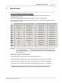
Suitable for programming Microchip® FLASH PIC(tm) microcontrollers.
Supports 4 different 300 mil. PICs: 8p, 14p, 18p and 28p.
Test buttons and LED indicators to carry out educational experiments e.g. the enclosed
programming examples.
Easily to connect to a PC via the serial port.
Enclosed is a Flash Microcontroller (PIC16F627) that can be reprogrammed up to 1000 times.
Software is included to compile and program your source code.
Power: 12 or 15V DC, min. 300mA, non-regulated adapter:
· (PS1205 / PS1208/PS1508 (230Vac))
· (PS1208USA (115Vac))
IBM-compatible PC, Pentium or higher, with Windows™ 95/98/ME/NT/2000/XP, CDROM and
a free serial RS232 port (cable not included, e.g. CW014).
Supports these FLASH microcontrollers:
· PIC12F629, PIC12F675, PIC16F83, PIC16F84(A), PIC16F871, PIC16F872,
· PIC16F873, PIC16F874, PIC16F876, PIC16F627(A),PIC16F628(A),PICF630, ….*
Dimensions: 145 mm x 100 mm.
(*) Visit our website for the updated list and software updates : www.velleman.be
4
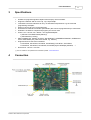
3
Connection
K8048 © 2003 Velleman Components
PIC programmer board
4
5
Hardware installation
·
Connect your PC with the K8048 via a 9-pin serial cable.
Use a free serial port and ensure that the installed software cannot cause an interrupt conflict
on this port when working with the K8048 e.g. executive programs for other programmers,
measuring devices, PDA's, etc...
·
·
Place selector (SW5) in the central position (standby).
Connect a non-regulated 12 to 15V DC adapter of min. 300mA with the K8048 via SK1
(compatible Velleman adapters: PS1205 / PS1208/ PS1508 (230Vac) or
PS1208USA(115Vac))
The 'POWER' LED (LD7) should now be the only one to light, indicating that the power supply
of the K8048 is OK.
·
Hardware installation
6
5
Programming Procedure
Programming the microcontrollers: preparations
·
·
·
·
6.1
Writing or modifying the source code: the source code is usually written in PIC assembler.
Look at the examples in the Velleman\K8048\Examples\ folder.
Compiling: the code you have written in comprehensible language is converted into machine
language. In this instance the Microchip PIC assembler software, MPASMWIN.EXE, is used.
Programming: the machine code is programmed in the processor via your PC and the K8048,
using the PROGPIC2.EXE software
Erase pic device: erasing the contents of a controller
Writing/changing a program
In order to write or modify a program: \Velleman\K8048\Examples\DEMOF627.ASM
Example of a program treated with 'NOTEPAD'.
6.2
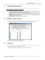
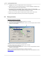
Compiling
Start MPASMWIN.EXE in the \Velleman\K8048 folder
The following setup screen is displayed (click on the number for more details):
K8048 © 2003 Velleman Components
6
PIC programmer board
1 This is the name and location of your source code file e.g. C:\TEST\DEMOF267.ASM
2. Select the format of the machine code you wish to create. Always select 'HEXADEMICAL' for
the K8048.
3. The variables are checked for spelling mistakes if this option is checked off (capitals or small
letters)
4. Determines to what extent error messages and warnings are generated in the error file.
Preferably you should tick off ALL MESSAGES of ERRORS ONLY.
5. Simply keep the default setting for this option. In the 'ON'-setting the macros are fully written out
in the LIST-file (xxx.LST).
6. This is the word length of the bytes. Always select 'INHX8M' in the machine code file for the
PROGPIC2 software that comes with the K8048. Other choices will result in illegible or non
functioning machine code.
7. Here you can click on the files you want to generate in addition to the HEX machine code.
Error file: the error messages are saved in this file.
List file: this file contains your source code + error messages and additional information.
There is no need to generate the CROSS REFERENCE & OBJECT files because they are not
compatible with the K8048 anyway.
8. Select the processor you're using. Important remark : with some PIC's the number is followed
by a generation code
e.g. PIC16F84A.
9. Indicate the column width in number of characters in the generated text files.
Click on <ASSEMBLE> when all the settings are correct.
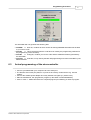
The following screen is displayed if no errors are found in the source code.
Programming Procedure
7
The assembler will now generate the following files:
· xxx.ERR => Error file, contains all errors and/or all warnings MPASM assembler has located
in your source code
· xxx.Hex
=> This is the actual machine code file to be used by the programming software for
the programming of the controller).
· xxx.LST => Listing file, contains your source code and the additional remarks generated by
the assembler.
· xxx.COD => Code file, is only used by the MPLAB programming environment and NOT by the
K8048 software.
6.3
Actual programming of the microcontroller
· Connect your K8048 with your computer via a free serial port.
· The IRQ line of this erial port (IRQ 3 or 4) must not be used by another device e.g. internal
modem.
· Connect the suitable power adapter and verify whether LD7 lights up ("Power LED").
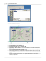
· Start the 'PROGPIC2, PIC programmer' program (in the folder C:\Velleman\K8048\).
· Click on 'FILE' -> 'OPEN' and select the compiled program (Hex 8M-file) you want to program.
K8048 © 2003 Velleman Components
PIC programmer board
8
· Check the settings of the software
1.
2.
3.
4.
5.
6.
7.
8.
Set the number of the serial port the K8048 is connected to.
Writing the CODE: (standard = ON).
Writing the EEPROM data (standard = ON).
Writing the configuration settings (standard = ON).
ERASE before WRITE: (standard = ON). This indicates that the controller is erased prior to
programming.
LOW VOLTAGE Programming: does not apply to the K8048. All controllers are programmed
with a programming voltage (VPP) of 13 and not 5V.
Select the microcontroller you are using. The included microcontroller belongs to one of the
two following types : PIC16F627 of PIC16F627A. Make sure you have selected the right type
number.
Normally speaking the configuration of the controller is identified with the __CONFIG compiler
directive as early as in the source code. Only experienced users can set these options
manually or adjust them.
Programming Procedure
6.3.1
9
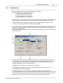
Programming
· Make sure that SW5 is placed in the central position (standby)
· Put the controller in the appropriate IC socket:
o insert the 8-pin PIC in socket IC1
o insert the 14-pin PIC in socket IC2
o insert the 18-pin PIC in socket IC3
o insert the 28-pin PIC in socket IC4
· Now put SW5 in the 'PROG' position. The warning LED LD9 starts to flash. This means that no
controller can be connected with or disconnected from a socket with SW5 in this position.
· Click on WRITE and the controller is programmed. You can monitor this process in the
'Activity' box. The 'READ/WRITE' indication lights (LED LD8).
· Put SW5 in the central position (STANDBY) again when the programming is finished. Only then
can you remove the controller or switch to test mode (see test push buttons and diagnostics
LEDs under 'Experiments').
Put SW5 in the 'RUN' position to test the program (if it was written to be used with the test push
buttons and LEDs.
1. Press this button to read out a program and data from a controller provided the latter is not
code-protected. PIC's for which the code protection bit has been activated can no longer be
read out, only erased which automatically means that all code will also be erased. The
hexadecimal machine code is saved in a text file.
* Attention: Put SW5 in the 'PROG'-position to use this function !
2. The controller is programmed. You can monitor this process in the 'Activity' box. The
'READ/WRITE' indication lights (LD8).
3. This key enables you to check if the PIC has saved the program you programmed
correctly.Remember that the controller must NOT be code-protected; otherwise you will not be
able to perform your check. During programming every byte is checked automatically to verify
whether it's been saved correctly. Only then will the code protection be activated.
K8048 © 2003 Velleman Components
PIC programmer board
10
* Attention: Place SW5 in the 'PROG'-position in order to use this function !
4. Enables the user to view and modify data stored in a controller's EEPROM. * Attention: Place
SW5 in the 'PROG'-position in order to use this function !
5. Leave this adjustment in the standard setting : 'NORMAL'. When you're having trouble
programming you can set the speed on 'HIGH' if you have a slow PC or you can select 'LOW' if
your PC is extremely fast. This compensates for the difference in speed.
6. Enables you to see which address or address area the software uses to read or write.
7. Name of the file loaded in the memory and to be used for the programming.
6.4
Erase pic device
Erasing the contents of a controller:
1.
2.
3.
Is used to erase the entire contents of a program from a controller.
Only used to erase the EEPROM data.
Can be used to deactivate the code protection. However, you will no longer be able to read the
contents or use the program.
* Attention: Put SW5 in the 'PROG' position to use this function !
1. Is used to erase the entire contents of a program from a controller.
2. Only used to erase the EEPROM data.
3. Can be used to deactivate the code protection. However, you will no longer be able to read the
contents or use the program.
Read the C:\Velleman\K8048\Examples folder for examples of programs.
Updates of the programming software and additional examples can be downloaded from our site
www.velleman.be
Programming Procedure
7
11
Experiments
Use of the experiment push buttons and LEDs:
The K8048 is equipped with a max. of 4 test inputs that can be operated manually with
SW1,SW2,SW3 and SW4.
The device also has 6 diagnostics LEDs that enable the user to simulate outputs.
Click on the link "cross-reference table" to determine for every IC socket which I/O line is linked to
which push button or LED.
8 pin PIC socket
14 pin PIC socket
18 pin PIC socket
28 pin PIC socket
LD1
GP2 (pin 5)
RC0 (pin 10)
RB0 (pin 6)
RA0 (pin 2)
LD2
GP4 (pin 3)
RC1 (pin 9)
RB1 (pin 7)
RA1 (pin 3)
LD3
NC
RC2 (pin 8)
RB2 (pin 8)
RA2 (pin 4)
LD4
NC
RC3 (pin 7)
RB3 (pin 9)
RA3 (pin 5)
LD5
NC
RC4 (pin 6)
RB4 (pin 10)
RA4 (pin 6)
LD6
NC
NC
RB5 (pin 11)
RA5 (pin 7)
SW1
GP5 (pin 2)
RC5 (pin 5)
RA0 (pin 17)
RB0 (pin 21)
SW2
NC
RA2 (pin 11)
RA1 (pin 18)
RB1 (pin 22)
SW3
NC
NC
RA2 (pin 1)
RB2 (pin 23)
SW4
NC
NC
RA3 (pin 2)
RB4 (pin 25)
Remarks: The I/O lines coming from a pushbutton have to be configured as inputs in the source
(a 1 in the TRIS-register
for that particular entrance). The I/O lines connected
with a LED must be configured as exits in the sources (a 0 in the TRIS-register for that
particular entrance).
Selecting an oscillator with the jumpers
These jumpers allow you to select which IC socket crystal X1 uses.
· Place the shunts in locations JP1 & JP2 for use with the 14-pin socket (e.g. PIC16F630).
· Place the shunts in locations JP3 & JP4 for use with the 18-pin socket (e.g. PIC16F627).
· Place the shunts in locations JP5 & JP6 for use with the 28-pin socket (e.g. PIC16F87x).
· No selection can be made for the 8-pin socket since you would lose two I/O's. With this
particular experiment board you can only use the internal oscillator with this socket.
K8048 © 2003 Velleman Components
12
PIC programmer board
Step-by-step execution of a sample program.
For our example we will use the program demo1.asm, a simple running light:
· Verify whether the adapter and the serial connection of your K8048/VM111 are connected and
make sure the programmer software has been installed on your PC.
· Compile the file 'demo1.asm' with MPASM.EXE (see Compiling)
· Start the programmer software, PICPROG2.EXE
· Check all settings (PIC16F627), the serial port and the communication speed always start with
the 'LOW' setting).
· Read in the compiled file, demo1.hex. (File...open file...)
· Put SW5 in the 'PROG' position.
· Click on 'WRITE' in the PICPROG2 software.
· Now you can monitor the writing process on the activity screen.
· Put SW5 in the 'RUN' position when the programming is completed. LEDs LD1 to LD6 should
now form a running light.
Experiments
8
13
ICSP
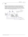
IICSP allows you to program controllers "in-circuit". This process is also known as code
downloading. This means quite simply that the chip in question is connected with a socket
consisting of four or five wires, viz. the ICSP bus. Several members of the PIC family can be
programmed or reprogrammed without having to remove them from the print or deactivating the
power supply. These IC's are converted to programming mode by applying the programming
voltage of 12 to 14V to the "/MCLR" pin. From this point onwards RB6 is used as a CLOCK input
while RB7 is modified into a DATA-input/output-connection.
K8048 © 2003 Velleman Components