1
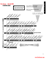
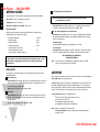
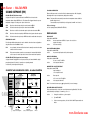
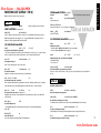
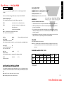
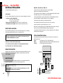
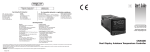
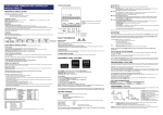
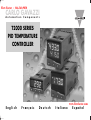
Flow Factor ~ 866-360-9830
CARLO GAVAZZI
A u t o m a t i o n
C o m p o n e n t s
T2000 SERIES
PID TEMPERATURE
CONTROLLER
English
Français
Deutsch
www.flowfactor.com
Italiano
Español
E n g l i s h
Flow Factor ~ 866-360-9830
INDEX
FUNCTIONS MENU
GETTING STARTED
Initial Set-up
AUTOTUNE
Tune or tune at setpoint program
PROPORTIONAL CYCLE-TIME
Cycle-time recommendations
PROGRAMMER
Ramp-Soak
SECOND SETPOINT (SP2)
Error messages
FUNCTION LIST
Level 1
Level 2
Level 3
Level 4
MECHANICAL INSTALLATION
DIN panel cut-out
Mounting
Cleaning
ELECTRICAL INSTALLATION
Sensor selection
SPECIFICATION
SAFETY AND WARRANTY
INSTRUMENT PANEL FEATURES
3
4
4
4
5
5
5
5
5
6
6
7
7
7
8
9
9
9
9
9
10
11
11
12
Green Display:
Orange Display:
Green LED:
Red/Orange LED:
!
This page can be photocopied and
used as a visual aid and bookmark when
working in other parts of the manual.
Process temperature or program Function/Option
Setpoint temperature or program Option (T20162 only)
Setpoint 1 output indicator
Setpoint 2 output indicator
ADJUSTMENTS
To
To
To
To
To
To
To
enter or exit program mode:
scroll through functions:
change levels or options:
view setpoint:
increase setpoint:
decrease setpoint:
reset an alarm or fault condition:
Notes:
Press
Press
Press
Press
Press
Press
Press
▲ ▼ together for 3 seconds
▲ or ▼
✱ ▲ together or ✱ ▼ together
✱
✱ ▲ together
✱ ▼ together
▲ ▼ together briefly
If in difficulty by becoming “lost” in program mode, press ▲ and ▼ together for 3
seconds to return to display mode, check the INSTRUMENT ADJUSTMENTS above and
try again.
When in program mode, after 60 seconds of key inactivity the display will revert to
either inPt : nonE or, if the initial configuration has been completed, the measured
value. Any settings already completed will be retained.
2
www.flowfactor.com
FUNCTIONS MENU
!
This page can be photocopied and
used as a visual aid and bookmark when
working in other parts of the manual.
E n g l i s h
Flow Factor ~ 866-360-9830
Range of Adjustment shown under description.
If applicable, factory settings shown in bold.
Note: The letter K appears in the instrument display
as the character K
LEVL 4 LOCK PROG NO.AL DIS.S DER.S
USER-PROTECTED SETTINGS
u
)*
r
d.2
;
2i
nly
d.2
;1
1i.
f/s
Ct3
do
;1
.2d
e (rea
e *
.2i;
.2r
t2; S2
sor
s
t
t
ic
ic
n
ts d; 1r
ut C; 1u
g
ale
ta t1; C S; o
ED n; 1n
en
en sen
ev ; rlY
ev SSd
u
c
o
e
r
sio
L
a
s
d
d
p
m
m
d
o
S
D
u
t
t
r
t 5%
P
ver unit
e b; C 1;
ut Sd
ut lY;
LL
d.2
urn n.
nit lo
ou
jus 25% full
O/ 1i.2
ito
jus
;A
r b SC; d
are nsult
utp nE; S
utp nE; r
ad to 2
on f; on
Mo r; hi;
Tun ; Ct ; oS
se 2d; 1
se .2n;
Ad to nsor
r
r
o
o
o
w
M
s
n
d
d
e
e
ET onE
.
o
4
t
A
0
0
.
f
r 0.
a 0.
f
n uP
v 1r
v 1n
a VA
a Ct
t
o
o
se
Ct
O
Co
Se
SP2 n
Re
Sp
SP1 n
Re
Ze
Re
Re
Se
RES n
So
LEVL 3 SP1.D SP2.D BURN REU.D REU.L SPAN ZERO CHEK READ TECH UER
CONFIGURE OUTPUT
SAFETY SETTINGS
C A L I B R AT I O N
RSET
P E R F O R M A N C E D ATA
;
l
;
nd
sor
na
ho
ly
bA
sen
Lt.
s
t % ortio
;
on
o;
%
sor
de old;
um ax to ale
nit Ar
t%
t%
um in to
V.L Cool
tpu prop
ut read
ion gree
o
u
u
e
t
d
u
im
h
p
im
p
p
c
d
sen
y u F; b SEt
t
m
x
m
m
t
t
;
o
olu e
ly
ll s
ut
ou %
%
al
mo V.hi; Lo;
pla ; ° rh;
min or
ou %
ou %
ma or
P2 tCH
res 0.1 d
nu 100 e on SP1 to 0
le Sens or fu cale Sens scale t inp E
dis E; °C Ph;
P1 100
P2 E; d i; FS,
P2 to 0
d S E; L
a
a
y
S
S
t
S
n
c
s
r
d
m
c
c
la
it 00
it 00
to mo
in non S.h
p 1o
t s 0.0 full
le non
le non PSi;
ad 0 to
co non nLin
t s 0.0 sen
F
Se
Se
Se
Lim 1
Lim 1
Dis
SP1 0
Re
Se
Se
Ma
LEVL 2 SP1.P HAND PL.1
PL.2
SP2.A SP2.B DISP HI.SC LO.SC INPT UNIT
MANUAL ADJUSTMENTS
SP2 MODES
RANGING
CONFIGURE INPUT
➔
INITIAL SET-UP ENTRY
)
f/s
in)
st
ec
)
st
or
or
/hy sor
5s
1.5
5m
)
/Hy ens
p
f
sec
ur
sec
in) en
te) (2
t) in (
in
e
ch d (
set d
ain % s )
1)
int cale
t.S
/of 1
81
(ga 5% s
rat g/ho
(ra sec
oa An
ff
ese 0 m
F
0m
r
po ll s
ark rK; A
l re An
(SP
r
on o 8
d/G 00
d
e
P
(
p
0
44
ua x b ff)
r Pa
n/o .1 to
mp 0 de
p 0xb
set or fu
an to 1 /3.6°
ck
im 20
e to 6
an to 2 8°F)
or 0.1 t )
n hold
1
n
a
a
t
o
o
b
b
o
a
2
R
lo
.
0
o
e
/
im
le
e
;
9
o
s
e
P
t
p
le f;
g
g
ff
p
°C
/1
ff;
(m 50% =
ec
tive to 5
tive 1 to
int 99
int on
tim ff;
un on
t S en sca
tim 0 t
0.1
ral
pro .1 de f/s (2
Cyc n.of
Pro .1 de 10°C
p o n; o
le n.o (20 s ffset to (In.t
jus +/– s full
tot oFF;
riva 0.5
riva Off;
ak Off;
eg Off;
tpo 0 to
tpo Off;
(
0
Se
SP2 0
So
Ad
Ram O
Se
O
SP2 O
Cyc O
De
De
Au
Int
SP1 0
LEVL 1 TUNE BAND INT.T DER.T DAC
➔
KEY ✱ ▼ OR ✱ ▲ TOGETHER TO CHANGE LEVELS OR OPTIONS
y
L
exit
5)
pla
AL
toy
(0.
dis
2;
au
ivit Er.t
g 6)
rm
LEV
ala
ram Y
nsit x d
agin 32 (
k V 3;
g
e
r
c
s
L
o
0
e
.
v
lo LE
pr ; StA
-A on
tive to 1
y a 1 to
le
le
rity E;
ab Auto
ab Off;
pla dir;
riva 0.1
cu non
Dis
Dis
Dis
Se
De
SP1 SETTINGS
CYC.T OFST SP.LK SPRR SPRN SOAK SET.2 BND.2 CYC.2
PROGRAMMER SETTINGS
SP2 SETTINGS
PROGRAM ENTRY
Level C only visible
when COMMS
Option fitted
:
ss
1
00
48
dre
8O
y
2
0:
ad
1:1
at
ivit
nt 55
e : 240 : 19k
t
e
rm :18E
a
2
act on
m
d r 200 600 ata fo 8n1
tru 0 to
Rx Off;
u
s
9
1
1
Ba
In
Tx/
D
KEY ▼ ▲ TO VIEW FUNCTIONS
LEVL C ADDR BAUD DATA DBUG
COMMS SETTINGS
3
www.flowfactor.com
E n g l i s h
Flow Factor ~ 866-360-9830
3 Select SP1 (Main setpoint output device)
GETTING STARTED
After power-up the controller requires programming with the following information:
Note: Dual Relay and Dual SSd Output Options Models have their outputs
pre-configured. Move to Step 4.
Type of Sensor (See list of temperature sensors p.11)
Operating unit (See list of units p.8)
Allocation of Output Device to SP1/SP2 (Relay or SSd)
Press and hold ✱ and use the ▲ or ▼ buttons to select SSd or rLY as required. The
controller will now read selected output device e.g. SP1.d : SSd
Temperature Setpoint
When the above information has been programmed into the controller it will be
operational with the following factory settings.
Proportional band/Gain
Integral time/Reset
Derivative time/Rate
10ºC/18ºF
5 mins
25 secs
Proportional cycle-time
(Typical setting for relay output)
DAC Derivative approach control
(Average setting for minimum overshoot)
20 secs
1.5
The instruments covered in this manual may be fitted with either a single or a dual
display. Where a single display shows more than one reading, it will alternate
between them.
4 To enter initial configuration into controller memory
Press and hold both ▲ and ▼ buttons for 3 seconds. The display will now read ParK
and measured variable (temperature) (eg. 23 ) ParK is displayed because a setpoint
has not yet been entered.
To display setpoint
Press and hold ✱ The displays will now read unit (eg. °C ) and 0
To enter setpoint
Press and hold ✱ and use ▲ button to increase or ▼ button to decrease the reading
and scroll to required setpoint value. (The digit roll-over rate increases with time).
THE CONTROLLER IS NOW OPERATIONAL
WITH FACTORY SETTINGS
Note:
For precise control of an application the controller may need to be TUNED.
Please see the following section on AUTOTUNE
INITIAL SET-UP
On power-up the controller will display the self test sequence followed by the initial
display inPt : nonE
1 Select input sensor.
Press and hold ✱ and use the ▲ or ▼ buttons to scroll through the sensor selection list
until the correct sensor is displayed. Release the buttons. The display will now read
selected sensor type e.g. inPt : tCs
Press ▲ once The display will now read unit : nonE
AUTOTUNE
This is a single shot procedure to match the controller to the process. Select either Tune or
Tune at Setpoint from the criteria given below.
The Tune program should be used when the load temperature is at or near ambient. The
procedure will apply disturbances when the temperature reaches 75% of the setpoint
value, causing overshoot which is monitored in order to adjust the DAC overshoot inhibit
feature. Care should be taken to ensure that any overshoot is safe for the process.
2 Select unit.
Press and hold ✱ and use the ▲ or ▼ buttons to scroll through the unit selection list
until the correct unit is displayed. Release the buttons. The display will read selected
unit e.g. unit : °C
Press ▲ once The display will now read SP1.d : nonE
The Tune at Setpoint program is recommended when:
● The process is already at setpoint and control is poor
● The setpoint is less than 100°C
● Re-tuning after a large setpoint change
● Tuning multi-zone and/or heat-cool applications.
Notes:
DAC is not re-adjusted by Tune at setpoint.
Proportional Cycle Time can be pre-selected before running the Autotune
program. (see p5)
4
www.flowfactor.com
Hereafter in the Manual the symbol (▲▼) signifies both buttons are held pressed
for 3 seconds to ENTER or EXIT Program mode.
E n g l i s h
Flow Factor ~ 866-360-9830
PROGRAMMER
RAMP-SOAK
TUNE OR TUNE AT SETPOINT PROGRAM
Enter program (▲▼) and from the display tunE : oFF press and hold ✱ and press ▲ to
display tunE : on or tunE : At.SP Exit program mode (▲▼).
The TUNE program will now start. The display will show tunE as the process temperature
climbs to setpoint.
Note: During tuning, the main setpoint (SP1) LED will flash.
When the TUNE or TUNE AT SETPOINT program is complete the PID values are entered
automatically. The process temperature will rise to setpoint and control should be stable. If
not, this may be because optimum cycle time is not automatically implemented. To set the
cycle time see PROPORTIONAL CYCLE-TIME.
PROPORTIONAL CYCLE-TIME
This feature enables the controller to ramp up or down from current temperature to a
target setpoint at a pre-determined rate. It then controls at the target setpoint for an
adjustable soak period before switching off the SP1 output.
Deg.
Target
setpoint
Deg.
Soak
Ramp °/hour
Ramp °/hour
Target
setpoint
Soak
Time
Time
The choice of cycle-time is influenced by the external switching device or load. eg.
contactor, SSR, valve. A setting that is too long for the process will cause oscillation and a
setting that is too short will cause unnecessary wear to an electro-mechanical switching
device.
Factory set
To use the 20 sec factory set cycle-time no action is needed whether autotune is used or
not.
To Manually Select AUTOTUNE Calculated CYCLE-TIME
When AUTOTUNE is completed, enter program (▲▼) and select CYC.t in Level 1. The
display will read CYC.t : 20 (the factory setting).
To view the new calculated optimum value, press and hold both ✱ and ▼ buttons until
indexing stops. The calculated value will be displayed eg. A16. If acceptable, exit program
(▲▼) to implement this setting.
To Pre-select Automatic Acceptance of AUTOTUNE Calculated CYCLE-TIME
Before AUTOTUNE is initiated select CYC.t in Level1, press and hold both ✱ and ▼ buttons
until indexing stops at A – –. Exit program (▲▼) to accept calculated value automatically.
To Manually Pre-select Preferred CYCLE-TIME
Before AUTOTUNE is initiated select CYC.t in Level 1, press and hold both ✱ and ▲ or ▼
buttons until indexing stops at preferred value then exit program (▲▼) to accept.
CYCLE-TIME RECOMMENDATIONS
Output Device
Factory Setting
Recommended Minimum
Internal relay: rLY/rLY1/rLY2
20 seconds
10 seconds
Solid state drives: SSd/SSd1/SSd2
20 seconds
0.1 seconds
Set Setpoint ramp rate (0 to 9995 deg/hour)
From SPrr in Level 1, press and hold ✱ and ▲ or ▼ to scroll to required ramp rate.
Set Soak (if required) 0 to 1440 minutes
From SoAk – – in Level 1, press and hold ✱ and ▲ or ▼ to scroll to required Soak time.
Set Ramp on (Off: On: Hold)
From Sprn in Level 1, press and hold ✱, then press ▲ to select On
Exit program (▲▼) to enter settings into memory and commence ramp to target setpoint.
Notes: In Ramp on configuration, if power is removed from the controller, the Ramp will
re-start when power is restored.
The Ramp hold option suspends the ramp at its last value.
If no Soak period has been set, control at target setpoint continues indefinitely.
SP2 deviation alarms follow the ramp setpoint and can be used to alarm “out of
limits” ramp rate.
WARNING
The Soak timer is triggered when the ramp setpoint reaches the target setpoint. If the
ramp rate is set too fast for the process, the Soak timer will be triggered before the
process temperature reaches the target setpoint.
5
www.flowfactor.com
E n g l i s h
Flow Factor ~ 866-360-9830
SP2 ALARM ANNUNCIATOR
SECOND SETPOINT (SP2)
When an SP2 alarm mode is selected in SP2.A the alarm annunciator -AL- is displayed,
alternating with the process temperature, during alarm condition.
SECOND SETPOINT (SP2) Alarm Output
Configure SP2 output to operate as an alarm from SP2.A in Level 2 and set the
temperature alarm setting in SEt.2 Level 1. The alarm will be triggered when the process
temperature changes according to the options listed below.
Notes:
dV.hi
Rises above the main setpoint by the value inserted at SEt.2.
dV.Lo
Falls below the main setpoint by the value inserted at SEt.2.
SP2 in cool strategy
See Full Operating Manual (ADVANCED SETTINGS)
BAnd
Rises above or falls below the main setpoint by the value inserted at SEt.2.
FS.hi
Rises above the main setpoint by a SEt.2 value that is greater than the setpoint.
ERROR MESSAGES
FS.Lo
Falls below the main setpoint by a SEt.2 value that is smaller than the setpoint.
SENSOR FAULT
Display flashes: inPt: FAiL
Indicates:
thermocouple burnout RTD/Pt100 open or short circuit or
negative over-range.
Action:
Check sensor/wiring
SUBSIDIARY SP2 MODE
The following additional alarm functions can be added to the above alarm configurations
using the features found in SP2.b in Level 2.
LtCh
Once activated, the alarms will latch and can be manually reset when the alarm
condition has been removed.
Hold
This prevents any alarm operation on power-up and is automatically disabled
once the process reaches setpoint in order to allow normal alarm operation.
SECOND SETPOINT (SP2) Proportional control output
Configure in Level 1 using CyC.2 to select proportional cycle time and bnd.2 to adjust
proportioning band. For Heat/Cool operation see Operating Manual.
In on/off mode, bnd.2 adjusts SP2 hysterisis.
SP2 OUTPUT AND LED INDICATION STATES - IN ALARM CONDITION
Alarm type
Deviation
ON-OFF
operating mode
SP2
Output state
Proportional
operating mode
SP2
LED state
SP2
Output state
SP2
LED state
DV.HI
The alarm will be automatically reset when the temperature returns within the
bnd.2 setting in Level 1.
The annunciator may be disabled by selecting function no.AL : on in level 4.
NON-VOLATILE MEMORY ERROR
Display flashes: dAtA : FAiL
Action:
De-power briefly. Replace unit if problem persists
MANUAL POWER ERROR
Display flashes: hAnd : FAiL
SP1 set to ON/OFF in CYC.t
Action:
Select proportional mode
IMMEDIATE FAIL ON AUTOTUNE START
Display flashes: tunE : FAiL
Setpoint display 0
1. No setpoint entered.
Action:
Enter setpoint
Action:
2. SP1 set to ON/OFF in CyC.t
Select proportional mode
Note: To reset and clear error press ▲▼ together briefly to cancel message.
DV.LO
BAND
BAND
: on-off mode only
Full scale
FS.HI
FAIL LATER DURING AUTOTUNE CYCLE
The thermal characteristics of the load exceed the Autotune algorithm limits. The failure
point indicated by any display 0.0 in tech e.g. Ctb = 0.0
Action:
FS.LO
Temperature above setpoint
1.
Change the conditions. eg. raise setpoint
2.
Try tunE : At.SP
3.
If the error message persists, call local CARLO GAVAZZI representative for
advice.
COOL
Strategy
6
Legend
Output ON
(Relay or SSd energised)
Output OFF
(Relay or SSd de-energised)
LED ON
www.flowfactor.com
FUNCTION LIST (LEVELS 1 TO 4)
Note: A Functions Menu is shown on page 3.
LEVEL 1
PROGRAMMER SETTINGS (see page 5)
[Factory settings] shown in brackets
Function
Options
SPrr
Sets the ramp rate
[0] to 9995 deg/hour
LEVL 1
Function
SELECT AUTOTUNE
tunE [oFF]
E n g l i s h
Flow Factor ~ 866-360-9830
Options
[Factory settings] shown in brackets
SPrn on [oFF] hoLd
Switches the ramp on or off, or hold at last ramp value
(see pages 4/5)
on ParK At.Sp
Used to switch the Autotune feature on and off, to select ParK or Autotune at setpoint.
ParK temporarily turns the output(s) off. To use select ParK and exit program mode. To
disable re-enter program at tunE and select oFF.
SP1 OPERATING PARAMETERS
bAnD
0.1 to * C/°F
[10ºC/18ºF]
SP1 proportional band/Gain or Hysteresis
* 25% sensor maximum Proportional control eliminates the cycling of on-off control. Heater
power is reduced, by time proportioning action, across the proportional band.
int.t oFF
0.1 to 60 minutes
SP1 integral time/reset
Auto-corrects proportional control offset error
[5.0]
dEr.t oFF
1 - 200 seconds
[25]
SP1 derivate time/rate
Suppresses overshoot and speeds response to disturbances
dAC 0.5 - 5.0 x bAnd
[1.5]
SP1 derivative approach control dAC
Tunes warm-up characteristics, independent of normal operating conditions, by controlling
when derivative action starts during warm-up (smaller dAC value = nearer setpoint).
CyC.t A – – on.oF
0.1 - 81 sec
[20]
SP1 proportional cycle-time (see pages 9/10)
Determines the cycle rate of the output device for proportional control. Select on.oF for
ON/OFF mode.
oFSt [0] to *
°C/°F
SP1 offset/manual reset
* ±50% bAnd. Applicable in proportional and ON/OFF mode with integral disable:
Int.t : oFF.
SP.LK [oFF]
on
Lock main setpoint
Locks the setpoint preventing unauthorised adjustment.
SoAK – – [oFF]
Sets the soak time
0 to 1440 min
SP2 OPERATING PARAMETERS
(see page 6)
[0]
SEt.2
0 to * °C/°F
Adjust SP2 setpoint
* Deviation Alarms DV.hi, DV.Lo, bAnd 25% sensor maximum.
* Full scale alarms FS.hi, FS.Lo sensor range f/s
bnd.2
0.1 - * °C/°F
Adjust SP2 hysteresis or proportional band/gain
(see CyC.2 setting)
* 25% sensor f/s
[2.0 °C/3.6°F]
CyC.2 [on.oFF]
0.1–81 seconds
Select SP2 ON/OFF or proportional cycle-time
Select on.oFF for ON/OFF mode, or the cycle rate of SP2 output device for proportional
mode.
LEVEL 2
LEVL 2
MANUAL CONTROL MODES
SPI.P
0 to 100 % ‘read only’
Read SP1 output percentage power
hAnd [oFF]
1 to 100 % (not in ON/OFF)
SP1 manual percentage power control
For manual control should a sensor fail. Record typical SP1.P values beforehand.
PL.1
100 to 0 % duty cycle [100]
Set SP1 power limit percentage
Limits maximum SP1 heating power during warm-up and in proportional band.
PL.2
100 to 0 % duty cycle [100]
Set SP2 percentage power limit (cooling)
7
www.flowfactor.com
E n g l i s h
Flow Factor ~ 866-360-9830
SP2 OPERATING MODES (see page 6)
Function
Options
SP2.A [nonE]
Main SP2 operating mode
burn Sensor burn-out/break protection
Caution: Settings affect fail safe state.
[Factory settings] shown in brackets
[uP.SC]
dn.SC
1u.2d
1d.2u
dV.hi dV.Lo bAnd FS.hi FS.Lo Cool
SP2.b [nonE]
LtCh hoLd nLin
Subsidiary SP2 mode: latch/sequence
Non-linear cool proportional band
[1r.2d]
1d.2d
1r.2r
1d.2r
dI.SP [1]
0.1
Select display resolution: for display of process temperature, setpoint, OFSt, Set.2, hi.SC,
LoSC.
rEu.L
[1n.2n]
1i.2n
1n.2i
1i.2i
inPt Select input sensor [nonE]
(See SENSOR SELECTION table, page 11)
SP1
Normal
Invert
Normal
Invert
SP2
Normal
Normal
Invert
Invert
SPAn [0.0]
to ±25% sensor maximum
Sensor span adjust
For recalibrating to align readings with another instrument e.g. External Meter, data logger.
See Full Operating Manual (ADVANCED SETTINGS).
LEVL 3
ZEro
[0.0]
to ±25% sensor f/s
Zero sensor error (see Sensor span adjust above).
OUTPUT CONFIGURATION
Note: ‘Read only’ after initial configuration. rSET ALL full reset to factory settings required
to change SP1.d subsequently.
8
SP2
Direct
Direct
Reverse
Reverse
Select SP1/2 LED indicator modes
Lo.SC [sensor minimum] sensor maximum
°C/ºF
Set scale minimum (default 0°C or 32°F)
LEVEL 3
SP1
Reverse
Direct
Reverse
Direct
Select Reverse on SP1 for heating and Direct for
cooling applications.
hi.SC sensor minimum [sensor maximum]
°C/°F
Set full scale
°C °F bAr Psi Ph rh SEt
SP2
Upscale
Downscale
Downscale
Upscale
rEu.d Select output modes: Direct/Reverse
Caution: Settings affect fail safe state.
INPUT SELECTION AND RANGING
unit [nonE]
Select °C/°F or process units
SP1
Upscale
Downscale
Upscale
Downscale
SP1.d [nonE] rLY SSd
Select SP1 output device
rLY1 rLY2 SSd1
SP2.d [nonE] SSd rLY
Read SP2 output device
(read only)
rLY2 rLY1 SSd2
Dual Relay and Dual SSd output options are factory set.
Note: (when in initial configuration only)Hold ✱ and ▲ or ▼ for 10 seconds to move
to or from output devices in shaded portion.
ChEK [oFF]
on
Select control accuracy monitor
rEAD [Var]
hi
Lo
Read control accuracy monitor
tECh [Ct A]
CT b Ct 1 Ct 2 Ct 3 Ct 4 oS 1
Read Autotune tuning cycle data (see Operating Manual)
UEr
uS
oS 2
Software version number
rSET [nonE] ALL
Resets all functions to factory settings
Caution: This selection will lose all of the current settings.
www.flowfactor.com
LEVEL 4
LEVL 4
E n g l i s h
Flow Factor ~ 866-360-9830
DIN PANEL CUTOUT
1/16 DIN: 45.0mm +0.6 / 0.0 wide, 45.0mm +0.6 / 0.0 high
Access to level 4 is gained through UEr in level 3. Press and hold ▲ and ▼ for 10
seconds.
1/32 DIN: 45.0mm +0.6 / -0 wide, 22.2mm +0.3 / -0 high
Maximum panel thickness 9.5mm
Enter level 4 at Lock, release ▲ and ▼ together. Display reads LoCK nonE
Minimum spacing 20mm vertical, 10mm horizontal
Program security using Lock
Select from three Lock options: Press and hold ✱, press ▲ to index.
MOUNTING
To mount a Controller proceed as follows:
LEV.3
locks level 3 and 4 only- Technical Functions.
1 Check that the controller is correctly orientated and then slide the unit into the cutout.
LEV.2
locks levels 2, 3 and 4 only - Configuration and
2 Slide the panel clamp over the controller sleeve pressing it firmly against the panel until
the controller is held firmly.
Technical Functions.
ALL
Note:
locks all functions LoCK ALL
Locked functions and options may be read.
Press ▼ to access following functions
Function
Options
4 When refitting the bezel assembly it is important to press it firmly into the sleeve until the
latch clicks in order to compress the gasket and seal to NEMA4X/IP66.
[Factory settings] shown in brackets
ProG [Auto]
StAY
Program mode auto-exit switch
Auto-exit returns display to normal if 60 seconds of key inactivity, select StAY to disable
di.SS dir
1 to 32
[6]
Display sensitivity
dir = direct display of input 1 = maximum, 32 = minimum sensitivity
0.1 to 1.0
CLEANING
Wipe down with damp cloth (water only)
Note: The controller should be isolated before removing or refitting it in the sleeve, and
electrostatic precautions should be observed when handling the controller outside
the sleeve.
no.AL [oFF]
on
Disable SP2 alarm annunciator -ALSelect on to disable -AL-
dEr.S
Derivative sensitivity
3 The controller front bezel and circuit board assembly can be unplugged from the sleeve.
Grasp the bezel firmly by the recesses on each side and pull. A screwdriver can be used
as a lever if required.
DIMENSIONS: MODELS T2032 / T2016
Model
Bezel*
Width
Height
Behind Panel
Width
Height
Overall
Length
Behind panel
Length*
[0.5]
MECHANICAL INSTALLATION
T2032
51.0
28.5
44.8
22.0
116.2
106.7
T2016
51.0
51.0
44.8
44.8
116.2
106.7
Dimensions in mm
* includes gasket
The Controllers are designed to be mounted either in a 1/16 or a 1/32 DIN panel cutout.
The units are sleeve mounted with the front bezel assembly rated NEMA4/IP66 provided
that:
● the panel is smooth and the panel cutout is accurate;
● the mounting instructions are carefully followed.
9
www.flowfactor.com
E n g l i s h
Flow Factor ~ 866-360-9830
ELECTRICAL INSTALLATION
EN61010 - /CSA 22.2 No 1010.1 92
(See important Safety Information page 12)
Compliance shall not be impaired when fitted to the final installation.
Designed to offer a minimum of Basic Insulation only.
OUTPUT DEVICES
Two of the following output devices are fitted to the controllers, depending on the model.
1 Solid state relay drive (SSd/SSd1/SSd2)
5Vdc +0/-15%, 15mA non isolating
To switch a remote SSR (or logic)
2 Miniature power relay (rLY/rLY1) 2A/250V AC resistive, Form A/SPST contacts.
3 Sub miniature power relay (rLY2) 1A/250V AC resistive, Form A/SPST contacts.
OUTPUT DEVICE ALLOCATION
Any of the available outputs may be chosen for the main setpoint (SP1), the remaining
device being automatically allocated to the second setpoint (SP2).
Dual relay or dual SSd output models are available to order. Please contact your
local CARLO GAVAZZI distributor for details.
Designed for use with the following supply voltages:
1). 100 - 240V 50-60 Hz 4.5 VA (nominal) +/-10% maximum permitted fluctuation
The body responsible for the installation is to ensure that supplementary insulation suitable
for Installation Category II or III is achieved when fully installed.
To avoid possible hazards, accessible conductive parts of the final installation should be
protectively earthed in accordance with EN6010 for Class 1 Equipment.
Output wiring should be within a Protectively Earthed cabinet.
Sensor sheaths should be bonded to protective earth or not be accessible.
Live parts should not be accessible without the use of a tool.
When fitted to the final installation, an IEC/CSA APPROVED disconnecting device should be
used to disconnect both LINE and NEUTRAL conductors simultaneously.
A clear instruction shall be provided not to position the equipment so that it is difficult to
operate the disconnecting device.
TYPICAL CONNECTION DIAGRAM
In this example the SSR driver output is allocated to SP1 and wired to switch the load
(heater) using an SSR.
F1 Fuse:
1A time lag type to IEC127. CSA/UL rating 250Vac
F2 Fuse:
High Rupture Capacity (HRC) Suitable for maximum rated load current
S1 Switch:
IEC/CSA/UL Approved disconnecting device
2). 12V - 24V (AC/DC) +/-20% 4.5 VA Polarity not required
WIRING THE CONNECTOR
Prepare the cable carefully, remove a maximum of 8mm insulation and ideally tin to avoid
bridging. Prevent excessive cable strain. Maximum recommended wire size: 32/0.2mm
1.0mm2 (18AWG).
Comms option
(when fitted)
9
+
INDUCTIVE LOADS
1
To prolong relay contact life and suppress interference it is recommended engineering
practice to fit a snubber (0.1uf/100 ohms) between terminals 5 and 6.
10 11 12 13
–
2
Sensor
+
–
3
4
5Vdc 15mA
5
6
Output Output
SP2
SP1
16
L
N
7
8
Supply
Open in
alarm
state
Sensor
CAUTION:
S1
Snubber leakage current can cause some electro-mechanical devices to be held
ON. Check with the manufacturers specifications.
14 15
+
SSR
–
Load
Line
F2
Neutral
F1
10
www.flowfactor.com
Linear process inputs
mV range:
SENSOR SELECTION
Thermocouples
tC
tC
tC
tC
tC
tC
tC
tC
tC
b
E
J
K
L
n
r
s
t
Description
Sensor range
Pt-30%Rh/Pt-6%Rh
Chromel/Con
Iron/Constantan
Chromel/Alumel
Fe/Konst
NiCrosil/NiSil
Pt-13%Rh/Pt
Pt-10%Rh/Pt
Copper/Con
Resistance
thermometer
rtd
Linearity
0 to 1800 °C
0 to 600 °C
0 to 800 °C
-50 to 1200 °C
0 to 800 °C
-50 to 1200 °C
0 to 1600 °C
0 to 1600 °C
-200 / 250 °C
2.0 *
0.5
0.5
0.25*
0.5
0.25*
2.0*
2.0*
0.25*
Pt100/RTD-2
0.25*
E n g l i s h
Flow Factor ~ 866-360-9830
0 to 50mV
Applicable to all inputs SM = sensor maximum
Calibration accuracy:
Sampling frequency:
Common mode rejection:
Series mode rejection:
Temperature coefficient:
Reference conditions:
Output devices
SSd/SSd1/SSd2:
Miniature power relay:
rLY and rLY1:
rLY2:
±0.25%SM ±1°C
input 10Hz, CJC 2 sec.
Negligible effect up to 140dB,
240V, 50-60Hz
60dB, 50-60Hz
150ppm/°C SM
22°C ±2°C, rated voltage after 15
minutes settling time.
solid state relay driver: To switch a
remote SSR 5Vdc +0/-15% 15mA
non-isolated
form A/SPST contacts (AgCdO)
2A/250ac resistive load
1A/250ac resistive load
Linear process inputs (Input mV range: 0 to 50mV)
Displays
Lin1
Lin2
Lin3
Lin4
Lin5
0 - 20mV
0 - 100
4 - 20mV
0 - 100
0 - 1000
0 - 1000
0 - 2000
setpoint limits
0 - 400
-25 - 400
0 - 3000
-250 - 3000
0 - 3000
Notes: 1 Linearity: 5-95% sensor range
2 * Linearity B:5° (70º - 500°C) K/N:1° >350°C
exceptions: R/S: 5°<300°C T:1° <- -25° >150°C
RTD/Pt100: 0.5° <-100°C
SPECIFICATION
Thermocouple
9 types
Standards:
CJC rejection:
External resistance:
Resistance thermometer
RTD-2/Pt100 2 wire
Standards:
Bulb current:
IPTS/68/DIN 43710
20:1 (0.05°/°C) typical
100Ω maximum
DIN 43760
(100Ω 0°C/138.5Ω 100°C Pt)
0.2mA maximum
±
±
±
±
±
0.5%
0.5%
0.5%
0.5%
0.5%
General
Displays:
Keypad:
Environmental
Humidity:
Altitude:
Installation:
Pollution:
Protection:
EMC emission:
EMC immunity:
Ambient:
Mouldings:
Weight:
Upper, 4 Digits, high brightness
green LED. 10mm (0.4”) high.
Lower, 4 Digits, Orange LED. 9mm
(0.35”) high (T20162 only)
Digital range -199 to 9999
Hi-res mode -199.9 to 999.9
LED output indicators - flashing
SP1 square, green; SP2 round, red
3 elastomeric buttons
Max 80%
up to 2000M
Categories ll and lll
Degree ll
NEMA 4X, lP66
EN50081-1 FCC Rules 15 subpart J
Class A
EN50082-2
0-50ºC (32-130°F)
flame retardant polycarbonate
130g (4.2 oz)
11
www.flowfactor.com
E n g l i s h
Flow Factor ~ 866-360-9830
SAFETY AND WARRANTY INFORMATION
INSTALLATION
Designed for use:
UL873 - only in products where the acceptability is determined by Underwriters
Laboratories Inc.
EN61010-1 / CSA 22.2 No 1010.1 - 92
To offer a minimum of Basic Insulation only.
Suitable for installation within Catagory II and III and Pollution Degree 2.
Copyright CARLO GAVAZZI 2000
Not to be reproduced without prior written permission from CARLO GAVAZZI. Whilst
every effort has been made to ensure the accuracy of the specifications contained in
this manual, due to our policy of continuous development, CARLO GAVAZZI reserves
the right to make changes without prior notice.
SEE ELECTRICAL INSTALLATION Page 10
It is the responsibility of the installation engineer to ensure this equipment is installed as
specified in this manual and is in compliance with appropriate wiring regulations.
CONFIGURATION
All functions are front selectable, it is the responsibility of the installing engineer to ensure
that the configuration is safe. Use the program lock to protect critical functions from
tampering.
ULTIMATE SAFETY ALARMS
Do not use SP2 as the sole alarm where personal injury or damage may be caused by
equipment failure.
WARRANTY
CARLO GAVAZZI warrant this product free from defect in workmanship and materials for
three (3) years from date of purchase.
1 Should the unit malfunction, return it to the factory. If defective it will be repaired or
replaced at no charge.
2 There are no user-servisable parts in this unit. This warranty is void if the unit shows
evidence of being tampered with or subjected to excessive heat, moisture, corrosion
or other misuse.
3 Components which wear, or damage with misuse, are excluded e.g. relays.
4 CARLO GAVAZZI shall not be responsible for any damage or losses however caused,
which may be experienced as a result of the installation or use of this product.
CARLO GAVAZZI liability for any breach of this agreement shall not exceed the purchase
price paid E. & O.E.
12
www.flowfactor.com