1
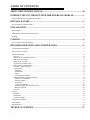
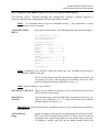
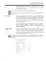
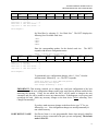
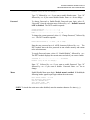
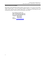
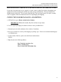
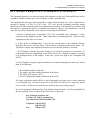
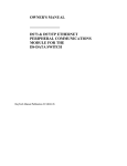
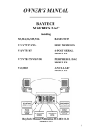
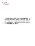
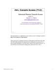
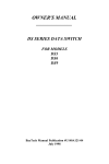
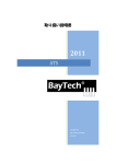
OWNER'S MANUAL ________________ DS72 NETWORK INTERFACE MODULE FOR DS SERIES AND DS-RPC PRODUCTS BayTech Manual Publication # U140A127 October 1998 Copyright 1998 by Bay Technical Associates, Inc. BayTech is a registered trademark of Bay Technical Associates, Inc. IBM, IBM PC, IBM PC/AT, IBM PC/XT are products and registered trademarks of International Business Machines Corporation. Windows 95 is a product and registered trademark of Microsoft Corporation. ii DS72 HOST MODULE OWNER’S MANUAL ABOUT THIS OWNER’S MANUAL ABOUT THIS OWNER’S MANUAL This document provides information required for installing and operating your Bay Tech equipment. It should allow the user to connect, power up, and access an applications menu where peripheral equipment can be controlled. We recommend reading this manual carefully, while placing special emphasis on correct cabling and configuration. If you have any problems with your installation, please contact a BayTech Applications Engineer at 228-467-8231, call toll free from anywhere in the United States using 1-800-523-2702 or contact us at our Web Site, www.baytechdcd.com. BayTech manufactures many remote site management products, data switches, data collection multiplexers, remote power controllers, and peripheral print sharers. If you would like information on any of these products, please contact BayTech Customer Service at the numbers previously listed. Conventions used in this manual include: CAUTION: This term is used to denote any condition that could possibly result in physical harm to personnel or damage to equipment. IMPORTANT: This term is used to denote conditions that could result in the loss of communications or to highlight the proper functioning of equipment. NOTE: This term is used to denote items of interest to the user. <cr>: Carriage Return or ENTER The information in this document is subject to change without notice. The statements, configurations, technical data, and recommendations in this document are believed to be accurate and reliable, but are presented without express or implied warranty. Users must take full responsibility for their applications of any products specified in this document. The information in this document is proprietary to Bay Technical Associates, Inc. In the interest of improving internal design, operational function, and/or reliability, Bay Technical Associates, Inc reserves the right to make changes to the products described in this document without notice. Bay Technical Associates, Inc does not assume any liability that may occur due to the use or application of the product(s) or circuit layout(s) described herein. We welcome any comments you may have about our products, and we hope that you will continue to look to BayTech for your data communication needs. iii TABLE OF CONTENTS ABOUT THIS OWNER’S MANUAL........................................................................ iii INTRODUCTION TO THE DS72 NETWORK INTERFACE MODULE ................. 1 PROGRAMMABLE FEATURES OF THE DS72................................................................................................................................ 1 DS72 QUICK START ................................................................................................ 3 EIA-232 SERIAL CONNECTION.......................................................................................................................................................... 3 INSTALLATION....................................................................................................... 5 UNPACKING............................................................................................................................................................................................... 5 PREPARING THE INSTALLATION SITE.......................................................................................................................................... 5 POWER......................................................................................................................................................................................................... 5 CABLING.................................................................................................................. 6 RJ-45 CABLES AND ADAPTERS......................................................................................................................................................... 6 DETAILED OPERATION AND CONFIGURATION............................................... 8 ACCESSING MAIN MENU..................................................................................................................................................................... 8 SELECTING A DEVICE........................................................................................................................................................................... 8 CONFIGURATION.................................................................................................................................................................................. 10 STATUS ................................................................................................................................................................................................. 10 SERIAL PORT CONFIGURATION ................................................................................................................................................ 11 PORT DEVICE NAME....................................................................................................................................................................... 12 PORT SELECT CODE......................................................................................................................................................................... 13 ATTENTION CHARACTER............................................................................................................................................................. 14 DISCONNECT TIME GUARD......................................................................................................................................................... 14 CONNECT PORT ID ECHO.............................................................................................................................................................. 14 LOGIN SETUP..................................................................................................................................................................................... 15 HEADER............................................................................................................................................................................................ 15 PASSWORD...................................................................................................................................................................................... 16 MENU................................................................................................................................................................................................. 16 AUTO CONNECT PORT ................................................................................................................................................................ 17 NETWORK PORT CONFIGURATION.......................................................................................................................................... 18 MODULE IP ADDRESS ................................................................................................................................................................ 18 SUBNET MASK.............................................................................................................................................................................. 19 GATEWAY....................................................................................................................................................................................... 19 ACTIVITY TIMEOUT .................................................................................................................................................................... 20 CARRIAGE RETURN TRANSLATION..................................................................................................................................... 20 BREAK LENGTH............................................................................................................................................................................ 20 UNIT ID.................................................................................................................................................................................................. 20 STATUS...................................................................................................................................................................................................... 21 SYSTEM ................................................................................................................................................................................................ 21 NETWORK............................................................................................................................................................................................ 21 LOGGED USERS................................................................................................................................................................................. 21 I/O MODULES RESET ........................................................................................................................................................................... 21 UNIT RESET ............................................................................................................................................................................................. 21 DIAGNOSTICS......................................................................................................................................................................................... 22 TECHNICAL SUPPORT......................................................................................... 23 iv TABLE OF CONTENTS REPACKAGING, SHIPPING AND RETURNING TO THE FACTORY ............... 24 FCC RADIO FREQUENCY INTERFACE STATEMENT...................................... 25 APPENDIX A: SPECIFICATIONS ......................................................................... 26 APPENDIX B – MODEM COMMANDS................................................................. 27 INDEX ..................................................................................................................... 28 v DS72 HOST MODULE OWNER’S MANUAL INTRODUCTION TO THE DS72 HOST MODULE INTRODUCTION TO THE DS72 NETWORK INTERFACE MODULE The DS72network interface module is a primary user interface for use with the BayTech DS-Series and DS-RPC units. The DS72 allows network users operating on a device using a TCP/IP stack with an ethernet connection, to access the main DS units, serial I/O modules, and (in the case of the DS-RPC) remote power switches. It also allows remote access via external modem to the serial port. This makes the DS72 an extremely versatile module, covering most applications. PROGRAMMABLE FEATURES OF THE DS72 Highlighted features indicate items most often programmed FEATURE DESCRIPTION ACTION PAGE NO. Enter baud rate, data bits, stop bits, parity, and Xon/Xoff Enter the device name 11 DS72 NETWORK INTERFACE MODULE Serial Port Configuration Sets serial port speed of the DS72 Default = 9600, 8, 1, N, Xon/Xoff Disabled Port Device Name Uniquely identifies the port (or device connected to the port). Default = Host EIA-232 Port Select Code ASCII character string used to select a port or module. Default = $BT Enter Port Select Code 13 Attention Character A character sent in sequence five times to invoke the main menu. Default = ; Enter Attention Character 14 Disconnect Time Guard Provides reliable binary data transmission. Default = Disabled Enable/Disable Disconnect Time Guard 14 Port ID Echo Echoes the module number and port number when you connect to the port. Default = Disabled Enable/Disable Connect Port ID Echo 14 Header Unit information that appears upon login Default = DS72 Enable/Disable Header 15 Password Password protection for telnet and EIA-232 connections. Default = Disabled Enable/ Disable, and Program Password 16 Menu Provides a menu interface for device selection, and configuration. Default = Enabled Enable/Disable Menu 16 Auto Connect Port Allows automatic connection to a specified port upon Telnet or EIA-232 connection. Default = Disabled IP Address for the DS72 to access the network. Default = 0.0.0.0 Enable,/Disable, and Program Auto Connect Port. Enter the IP Address in dotted decimal format 0.0.0.0 17 Subnet Mask Consists of four bytes, each byte ranging from 0 to 255. Default = 0.0.0.0 Enter the Subnet Mask in dotted decimal format 0.0.0.0 19 Gateway Consists of four bytes, each byte ranging from 0 to 255. Default = 0.0.0.0 Enter the Gateway in dotted decimal format. 0.0.0.0 19 IP Address 1 12 18 DS72 HOST MODULE OWNER’S MANUAL INTRODUCTION TO THE DS72 HOST MODULE Activity Timeout Carriage Return Translation Break Length Unit ID Provides a timeframe for unit disconnect due to inactivity from 1 to 120 minutes. Default = 0 (disabled Enables the Telnet processor to strip linefeeds or nulls which follow carriage returns. Default = disabled. Provides the time frame, for a break command, in msecs, from 1 to 9999 msecs. Default = 350 msecs. Unique ID for DS72 module. Default = DS72 Enter the timeframe or 0 to disconnect. Press “E” to enable this function Enter the timeframe in 1 msec increments between 1 and 9999 msecs. Enter unit ID 20 20 20 20 RS-232 Interface For Local Access or Connection to external modem for dial backup Ethernet Interface Telnet Access RS-232 Console Connection Power Connection Control Port Access Power Control Router DSU Hub Server 2 DS72 HOST MODULE OWNER’S MANUAL DS72 QUICK START DS72 QUICK START This section describes the basic steps required to set up and configure your DS72. If you need to acquaint yourself further with the setup, configuration, and operations, see “Detailed Operations and Configuration” beginning on page 8. GETTING STARTED Before the DS72 can be used within a network, there are a few parameters which must be configured. For an initial setup, connect the serial port of your computer to the RJ-45 port labeled “EIA-232” on the DS72 module using the 9FRJ45PC-4 adapter and the RJ08X007 (8 pin crossed) cable. With standard serial communications software or a terminal, set serial communications parameters to 9600 bps, 8 data bits, 1 stop bit, and no parity. This will allow direct communications with the DS72 module. Apply power to the DS-Series unit. The following main menu will appear: Data Switch Series - F.1.00 Bay Technical Associates Unit ID: BAYTECH DS72 Port Select Code: $BT Attention Character: ; Device A (2,1)...........1 Device B (2,2)...........2 Device C (2,3)...........3 Device D (2,4)...........4 DS-RPC (3,1)...........5 (if connected in a DS-RPC unit) Configure.......................C Status..........................S I/O Modules Reset...............RM Unit Reset......................RU Exit............................X Logout..........................T Enter Request : NOTE: Depending on the DS series or DS-RPC model, the menus may vary according to the number of DS74 modules installed in the unit. At a minimum, the IP Address, Subnet Mask and Gateway must be programmed in order to access the unit via your network. At the “Enter Request:” prompt, type “C” followed by <cr>. The following menu is displayed: 3 DS72 HOST MODULE OWNER’S MANUAL DS72 QUICK START Copyright(C) Bay Technical Associates 1998 DS-72 Data Switch Series - Telnet Host Module Revision F.1.00 Module 1 Status..........................1 Serial Port Configuration.......2 Port Device Name................3 Port Select Code................4 Attention Character.............5 Disconnect Timeguard............6 Connect Port ID Echo............7 Login Setup.....................8 Network Port Configuration......9 Unit ID.........................10 Configure Another Module........11 Exit............................X,CR Type “9”, followed by <cr> to access the Network Port Configuration. The following menu is displayed: Network Configuration IP Address: 0.0.0.0 Subnet Mask: 0.0.0.0 Gateway: 0.0.0.0 Ethernet Address: 00.C0.48.06.1A.81 Connection Inactivity Timeout (mins): 0 Carriage Return Translation: Disabled Break Length (msecs): 350 IP Address........................1 Subnet Mask.......................2 Gateway...........................3 Activity Timeout..................4 Carriage Return Translation.......5 Break Length......................6 Exit..............................X,CR Enter Request : Selections 1 and 2 will allow you to input the address in a dotted decimal format. For example, typing “1”, followed by <cr> will display: Enter IP address in dotted decimal form : Enter the address in the following format: nnn.nnn.nnn.nnn where n is any number. If you are unsure of this address, contact your network administrator. The subnet mask and gateway are programmed in a similar fashion. When programming is complete, type “X” followed by <cr>. The system must be reset for these settings to be applicable. If this is not an initial set-up and password has been enabled, you are prompted to login. After logging in successfully, access the main menu by sending the attention character five times (;;;;;). 4 DS72 HOST MODULE OWNER’S MANUAL INSTALLATION INSTALLATION UNPACKING Compare the unit and serial number of the equipment you received to the packing slip located on the outside of the box. Inspect equipment carefully for damage that may have occurred in shipment. If there is damage to the equipment or if materials are missing, contact BayTech customer service at 228-4678231 or call toll free inside the United States at 800-523-2702. NOTE: Keep the shipping container and packing material in the event future shipment is required. PREPARING THE INSTALLATION SITE The installation area should be clean and free of extreme temperatures and humidity. POWER CAUTION: This unit is intended for indoor use only. Do not install near water or expose this unit to moisture. To prevent heat buildup, do not coil the power cord when in use. Do not use extension cords. Do not attempt to make any internal changes to the power source. Do not attempt to modify any portion or component of a DS72 module unless specifically directed by BayTech personnel. BayTech will perform most internal changes. CAUTION: Before removing or replacing any modules, turn off main power switch located on the DS-Series Base Unit. Communication to the DS-Series Data Switch will be disrupted while power is off. 5 DS72 HOST MODULE OWNER’S MANUAL CABLING CABLING RJ-45 CABLES AND ADAPTERS IMPORTANT: The DS72 network interface module has an RJ-45 port which uses an 8-pin crossed modular cable to connect to a local EIA-232 device such as a computer terminal or external modem. Most serial computers do not have RJ-45 connections; therefore an adapter is provided with this unit to convert from a DE-9 connector to an RJ-45 connector (Bay Tech Part No. 9FRJ45PC-4). An adapter to convert from a DB-25 connector to an RJ-45 connector is also available from Bay Tech, upon request (Bay Tech Part No. 25FRJ45PC-4). The 8-pin crossed modular cable is configured to operate with these adapters. CAUTION: All power should be removed from the DS72 unit prior to removing or installing cables. The DS72 Ethernet connection requires a straight cable between the ethernet port of the DS72 module and the network hub. The “LINK” light will light green when a good link has been established. Pin 1 EIA-232 Signal Handshake Out 2 3 Gnd Handshake Out 4 5 6 7 8 TX Out RX In Handshake In Gnd Handshake In DS72 EIA-232 RJ-45 Pin/Signal Definition Description (DTR) Line Driver Inactive State = High: +12V when power is applied. Used as a handshake line to enable/disable the receiving of characters. Signal ground (RTS) Line Driver Inactive State = High: +12 V when power is applied. Not used to enable/disable. Transmit Data (data out) Receive Data (data in) (DSR) Handshake In. –12V when not used. Signal ground (CTS) Used as a handshake line to enable/disable the receiving of characters. 6 DS72 HOST MODULE OWNER’S MANUAL CABLING RJ-45 RJ-45 CONDUCTOR PIN PIN 1 1 2 2 3 3 4 4 5 5 6 6 7 7 8 8 COLOR COLOR BLUE ORANGE BLUE BLACK BLACK RED RED GREEN GREEN YELLOW BROWN YELLOW GRAY Fig 4: Crossed 8-pin Modular Cable BayTech Part No. RJ08X007 Fig 5: DE-9 PC Serial Port Adapter BayTech Part No. 9FRJ45PC4 7 ORANGE BROWN GRAY DS72 HOST MODULE OWNER’S MANUAL DETAILED OPERATION AND CONFIGURATION DETAILED OPERATION AND CONFIGURATION The following section, “Detailed Operation and Configuration,” provides a detailed approach to accessing, operating, and configuring the DS72 network interface module. NOTE: It is important that you type all commands correctly. Any combination of wrong entries results in an error message. ACCESSING MAIN MENU Apply power to the module. The following header and main menu appear: Data Switch Series - F.1.00 Bay Technical Associates Unit ID: BAYTECH DS72 Port Select Code: $BT Attention Character: ; Device A (2,1)...........1 Device B (2,2)...........2 Device C (2,3)...........3 Device D (2,4)...........4 DS-RPC (3,1)...........5 Configure.......................C Status..........................S I/O Modules Reset...............RM Unit Reset......................RU Exit............................X Logout..........................T Enter Request : NOTE: Depending on the DS-Series model, the menus may vary according to the number of DS74 modules installed in the unit. If this is not an initial set-up and Password has already been enabled, you are prompted to login. After logging in successfully, invoke the main menu by sending the attention character five times (;;;;;). NOTE: Password feature is case sensitive. SELECTING A DEVICE There are two methods of selecting a device, menu driven selection and ASCII character string method. Menu Driven Selection From the main menu, select the number that corresponds to the device you wish to access, followed by <cr>. To return to the main menu, send the attention character five times (;;;;;). IMPORTANT: ASCII Character String and Binary modes are only available when connected to the serial port. ASCII Character String Another method of selecting devices and operating the DS-Series and DS RPC is the ASCII character string method. To select a device located on a peripheral Port, type $BTm,p where m is the module and p is the port. To configure a module, type $BT and the module number followed by 8 DS72 HOST MODULE OWNER’S MANUAL DETAILED OPERATION AND CONFIGURATION <cr>, then $CONFIG followed by <cr>. This will allow access to the configuration menu for that module. Once configuration is complete, type X for “Exit” followed by <cr>. To access the main menu, type the attention character five times. NOTE: You must exit main menu to send ASCII character string commands. NOTE: While operating using the ASCII Character String method, consider placing the DSSeries in binary mode. Binary Mode If binary data containing the port select code is sent to a module, the DSSeries may interpret the data as a command to change ports. Binary mode prevents such an occurrence by placing the DS-Series in a mode which does not look at the data. This provides a reliable binary data transmission. However, before a connection can be made to another port, the binary mode must be terminated. Place the port in binary mode by sending the port select code, a capital B, and a carriage return ($BTB). For example, if using the default Port Select Code ($BT), place Module 2, Port 1 in binary mode by typing $BT2,1<cr>$BTB<cr>. Terminate Binary Mode From the terminal emulation software, send a BREAK condition command to terminate binary mode. You may have to consult the software users’ manual for the specific BREAK condition command for the emulation software you are using. For example, the BREAK condition command for PROCOMM PLUS is “Alt B.” NOTE: The break length for emulation software is programmed within that software. The break length for a TELNET session is programmed within the BayTech firmware. This procedure is discussed on page 20. Data Switch Series - F.1.00 Bay Technical Associates Unit ID: BAYTECH DS72 Port Select Code: $BT Attention Character: ; Device A (2,1)...........1 Device B (2,2)...........2 Device C (2,3)...........3 Device D (2,4)...........4 DS-RPC (3,1)...........5 Configure.......................C Status..........................S I/O Modules Reset...............RM Unit Reset......................RU Exit............................X Logout..........................T Enter Request : 9 DS72 HOST MODULE OWNER’S MANUAL DETAILED OPERATION AND CONFIGURATION DS72 CONFIGURATION If you are using the Menu Selection Method, select C, “Configure,” followed by <cr> from the DS72 Main Menu. The following selection menu appears: Configuration Module 1........................1 Module 2........................2 Module 3........................3 Select Port.....................S Exit............................X,CR Enter request: If you are using the ASCII Character String Method, exit the main menu, then select the module to configure. To select Module #1, type $BT1<cr>. The DS72 responds “Requested Connection Made.” Send the ASCII configuration command $CONFIG. The configuration menu appears. Enter the number of the module to configure, followed by <cr>. To configure the host module 1, select #1. The following configuration menu appears for the DS72: Copyright(C) Bay Technical Associates 1998 DS-72 Data Switch Series - Telnet Host Module Revision F.1.00 Module 1 Status..........................1 Serial Port Configuration.......2 Port Device Name................3 Port Select Code................4 Attention Character.............5 Disconnect Timeguard............6 Connect Port ID Echo............7 Login Setup.....................8 Network Port Configuration......9 Unit ID.........................10 Configure Another Module........11 Exit............................X,CR Enter Request: STATUS View the status of most user programmable features by selecting #1, “Status,” from the configuration menu, followed by <cr>. The following menu appears: Installed Modules : Port Select Code is.............$BT Attention Character is .........; Disconnect Time Guard is........Enabled Port ID Echo is.................Device Name Unit ID is......................BAYTECH DS72 Network Setup : Ethernet Address................00.C0.48.06.1A.81 IP Address......................200.4.2.65 Subnet Mask.....................255.255.255.0 Gateway.........................200.4.2.1 Inactivity Timeout (mins).......1 Break Length (msecs)............350 10 DS72 HOST MODULE OWNER’S MANUAL DETAILED OPERATION AND CONFIGURATION Login Setup : Header is.......................Enabled Password is.....................Disabled Menu is.........................Enabled Auto Connect Port is............Module 3,Port 1 Auto Connect is.................Disabled SERIAL PORT CONFIGURATION Port 1 Device Name EIA-232 Save.......1 Baud Rate..2 Word Size..3 Stop bits..4 DS72 modules perform data rate conversions for devices using different serial configurations .See Appendix A, “SPECIFICATIONS” for available serial parameters. Default Serial Port Configurations are 9600 bps, 8 data bits, 1 stop bit, no parity, Xon/Xoff disabled, RTS high, and DTR low. From the configuration menu, select #2, “Serial Port Configuration”, followed by <cr>. The DS72 unit displays the following table: Baud Rate 9600 Module 1 Serial Port Configuration : Word Stop Parity Xon/ Size Bits Xmit 8 1 None Off Xoff/ Recv Off Line DTR High Drive RTS High Parity............5 Xon/Xoff..........6 RTS Line Driver...7 DTR Line Driver...8 Enter Request : Select the corresponding number to configure baud rate, word size, stop bits, parity... NOTE: DTR is unchangeable when configuring the serial port. For example, to change the baud rate to 115.2K, select #2, “Set Baud Rate,” followed by <cr>. The DS71 displays the following list of available baud rates: 1 for 300 2 for 600 3 for 1200 4 for 2400 5 for 4800 6 for 9600 7 for 19200 8 for 38400 9 for 57.6K A for 76.8K B for 115.2K Enter Request : Type "B" for 115.2K baud rate. configuration status: 11 The DS72 responds with the new DS72 HOST MODULE OWNER’S MANUAL DETAILED OPERATION AND CONFIGURATION Port 1 Device Name EIA-232 Save.......1 Baud Rate..2 Word Size..3 Stop bits..4 Baud Rate 115.2K Module 1 Serial Port Configuration : Word Stop Parity Xon/ Size Bits Xmit 8 1 None Off Xoff/ Recv Off Line DTR High Drive RTS High Parity............5 Xon/Xoff..........6 RTS Line Driver...7 DTR Line Driver...8 Enter Request : Set Word Size by selecting #3, “Set Word Size.” The DS72 displays the following list of available word sizes: 1 2 3 4 For For For For 5 6 7 8 Enter the corresponding number for the desired word size. responds with the new configuration status: Port 1 Device Name EIA-232 Save.......1 Baud Rate..2 Word Size..3 Stop bits..4 Baud Rate 9600 Module 1 Serial Port Configuration : Word Stop Parity Xon/ Size Bits Xmit 7 1 None Off Xoff/ Recv Off Line DTR High The DS72 Drive RTS High Parity............5 Xon/Xoff..........6 RTS Line Driver...7 DTR Line Driver...8 Enter Request : To permanently save configuration changes, select 1, “Save,” from the selection menu, followed by <cr>. The DS72 responds: Change Host Device to Match NEW Configuration Before Answering this Request Save Changes Permanently ? (Y/N) : IMPORTANT: This message reminds you to change the serial port configuration of the host terminal to match the new configuration changes made to the serial port on the host module before answering the question. If they do not match, the DS72 will be unable to interpret the next command, and you will be unable to access any connected unit. If this happens, recycle power and reconfigure the unit. Make any necessary changes to the host device before answering "Save Changes Permanently?" If you have made necessary changes to the host device, type "Y" for yes, followed by <cr>. New configuration changes are stored permanently in non-volatile memory. PORT DEVICE NAME Port Device Name is a user programmable feature that uniquely identifies the port (or device connected to the port) you are configuring. The default name is EIA-232. 12 DS72 HOST MODULE OWNER’S MANUAL DETAILED OPERATION AND CONFIGURATION Select #3, “Port Device Name,” followed by <cr>. The DS72 module responds: Port 1 Device Name EIA-232 Baud Rate 9600 Module 1 Serial Port Configuration : Word Stop Parity Xon/ Size Bits Xmit 8 1 None Off Xoff/ Recv Off Line DTR High Drive RTS High Enter Port Device Name (Max. 16 characters): or press ENTER for no change ...........: Enter a new port device name up to 16 characters. For example, if you are using multiple DS units on a network, and you want to name the host device Southeast Region, type "SE REGION" followed by <cr>. The module responds: Port 1 Device Name SE REGION Baud Rate 9600 Module 1 Serial Port Configuration : Word Stop Parity Xon/ Size Bits Xmit 8 1 None Off Xoff/ Recv Off Line DTR High Drive RTS High Enter Port Device Name (Max. 16 characters): or ENTER for no change ...........: PORT SELECT CODE The Port Select Code is an ASCII character string sent by the host terminal to the DS72 module to select an I/O port on a DS74 peripheral module. The Port Select Code can range from 1 to 8 characters and is user programmable. Default Port Select Code is $BT. NOTE: The Port Select Code is only applicable for operation using the serial port. From the configuration menu, select #4, “Port Select Code,” followed by <cr>. The host module displays the current port select code and asks if you want to change: Port Select Code is................$BT Change It ? (Y/N) : Type "Y" to change the port select code, followed by <cr>. The host module responds: Enter Port Select Code (Max. 8 characters): Enter a new port select code followed by <cr>. For example, if you want to identify the port select code as “BAYTECH,” type BAYTECH followed by <cr>. The DS72 module displays the new port select code and asks if you want to change. Port Select Code is................BAYTECH Change It? (Y/N): If there are no additional changes, type "N" for no, followed by <cr>. The DS72 module stores the new port select code permanently in non-volatile memory and returns to the configuration menu. 13 DS72 HOST MODULE OWNER’S MANUAL DETAILED OPERATION AND CONFIGURATION ATTENTION CHARACTER The Attention Character is a character used in sequence to invoke the main menu. Default Attention Character is a semicolon (;). From the configuration menu, select #5, “Attention Character,” followed by <cr>. The host module displays the current attention character and asks if you want to change. Attention Character is............ ; Change It? (Y/N): For example, if you want to change the attention character followed by <cr>. The DS72 module responds: type “Y” Enter Attention Character: Enter a new attention character. For "%", type % followed by <cr>. The DS72 displays the new attention character and asks if you want to change. Attention Character is............ % Change It? (Y/N): If there are no additional changes, type “N” for no followed by <cr>. The DS72 module stores the new attention character in non-volatile memory and returns to the main configuration menu. DISCONNECT TIME GUARD When using the Attention Character Method, it is possible for the same character being sent as data from another device to be interpreted by the DS72 as the attention character. This could result in unwanted port disconnection. If enabled, the Disconnect Time Guard feature provides reliable binary data transmission by providing a one-second “timeguard” after the DS72 receives the attention character. If more data is received within the delay period, the DS72 treats the character as data, not an attention character; thereby preventing unwanted port disconnection. Default Disconnect Time Guard is disabled. From the configuration menu, select #6, “Disconnect Time Guard,” followed by <cr>. The DS72 module displays the current status and asks if you want to change: Disconnect Time Guard is..................Disabled Enable? (Y/N, CR for no change): Type “Y” or “N” followed by <cr> to toggle the existing status or type <cr> for no change. The DS72 module stores the Disconnect Time Guard selection in non-volatile memory and returns to the configuration menu. CONNECT PORT ID ECHO When enabled, Connect Port ID Echo identifies the module number and port number you are connected to. Choose the port device name or the module and port number to echo when a DS72 module selects a port on a DS74 module. Default Connect Port ID Echo is disabled. From the configuration menu, select #7, “Connect Port ID Echo,” followed 14 DS72 HOST MODULE OWNER’S MANUAL DETAILED OPERATION AND CONFIGURATION by <cr>. The DS72 module presents the current status of Port ID Echo and asks if you want to change: Port ID Echo is....................Disabled Change It? (Y/N): Type “Y” followed by <cr> to toggle Connect Port ID Echo or “N” for no followed by <cr>. If you answer yes, the DS72 module responds: Port ID Echo is...................Device Name Disable Port ID Echo..............1 Use Module, Port Number...........2 Use Device Name...................3 Exit..............................X,CR Enter Request : If you are enabling Port ID Echo, choose #2 to echo the module and port number, followed by <cr>. Choose #3 to echo the device name, followed by <cr>. The DS72 module stores the selected Connect Port ID Echo in nonvolatile memory and returns to the configuration menu. NOTE: If you choose #3, “Use Device Name,” the programmed Port Device Name for the selected DS74 is used. LOGIN SETUP This configures how the DS72 responds upon login. You can Enable/Disable the Header and Menu and/or Enable/Disable/Program Password and Auto Connect Port. From the configuration menu, select #8, “Login Setup,” followed by <cr>. The following menu appears: Header..........................1 Password........................2 Menu............................3 Auto Connect....................4 Exit............................X,CR Enter Request : Header If enabled, the following header appears with the main menu upon initiation of power or after a modem connection to the host module has been established. If disabled, the header does not appear with the main menu. Default Header is enabled. Data Switch Series – F.1.00 Bay Technical Associates Unit ID: BAYTECH DS72 Port Select Code: $BT Attention Character: ; From the selection menu, select #1, “Header,” followed by <cr>. The DS72 displays the current header status and asks if you want to enable: 15 DS72 HOST MODULE OWNER’S MANUAL DETAILED OPERATION AND CONFIGURATION Header is......................... Disabled Enable? (Y/N, CR for no change): Type “Y” followed by <cr> if you want to enable Header status. Type “N” followed by <cr> if you want to disable Header. Enter <cr> for no change. Password To change Password or Enable/Disable Password upon login, select #2, “Password,” from the selection menu, followed by <cr>. Default Password is BTA, disabled. The DS72 module responds: Change Password....................1 Enable/Disable.....................2 Exit...............................X, CR To change the current password, select #1, “Change Password,” followed by <cr>. The DS72 module responds: Enter New Password (1 - 8 char., CR to end): Enter the new password up to 8 ASCII characters followed by <cr>. The DS72 module stores the new password in non-volatile memory and returns to the selection menu. To toggle Password status, select #2, “Enable/Disable,” followed by <cr>. The DS72 module displays the current status and asks if you want to enable: Password is ......................... Disabled Enable? (Y/N, CR for no change): Enter “Y” followed by <cr> if you want to enable Password. Type “N” followed by <cr> if you want to disable Password. Enter <cr> for no change. Menu Enable/Disable Menu upon login. Default menu is enabled. If disabled,the following header appears upon login without the main menu: Data Switch Series - F.1.00 Bay Technical Associates Unit ID: BAYTECH DS72 Port Select Code: $BT Attention Character: ; NOTE: To invoke the main menu when disabled, enter the attention character five times (;;;;;). 16 DS72 HOST MODULE OWNER’S MANUAL DETAILED OPERATION AND CONFIGURATION If enabled, the following header and menu appears: Bay Technical Associates Unit ID: BAYTECH DS72 Port Select Code: $BT Attention Character: ; Device A (2,1)...........1 Device B (2,2)...........2 Device C (2,3)...........3 Device D (2,4)...........4 DS-RPC (3,1)...........5 Configure.......................C Status..........................S I/O Modules Reset...............RM Unit Reset......................RU Exit............................X Logout..........................T To toggle the menu status, select #3, “Menu,” from the selection menu, followed by <cr>. The DS72 module displays the current status and asks if you want to change: Menu is............................ Disabled Enable? (Y/N, CR for no change): Type “Y” followed by <cr> if you want to enable Menu. Type “N” followed by <cr> if you want to disable Menu. Type <cr> for no change. Auto Connect Port If Auto Connect Port has been enabled, then the initiation of power to the DS72 module will connect the user to the designated I/O port. This also happens when a connection is established via the serial port. NOTE: The auto connect port has priority over the login setup menu. If Auto Connect Port is enabled, the header and main menu are automatically disabled. Select # 4, “Auto Connect Port”, from the selection menu, followed by <cr>. The following Auto Connect Port menu appears: Auto Connect Port is..............Module 3,Port 1 Auto Connect is...................Disabled Change Auto Connect Port..........1 Enable/Disable....................2 Exit..............................X,CR Enter Request : The DS72 module displays the current auto connect port and its current status. To change the auto connect port module number and port number, select #1, “Change Auto Connect Port,” followed by <cr>. The DS72 module responds: Auto Connect Port is..............Module 3,Port 1 Enter Auto Connect Module (2 to 9) :3 Enter Auto Connect Port (1 to 4) :1 Auto Connect Port is..............Module 3,Port 1 17 DS72 HOST MODULE OWNER’S MANUAL DETAILED OPERATION AND CONFIGURATION Enter the module to connect automatically, followed by <cr>. Enter the port to connect automatically, followed by <cr>. The DS72 module stores the new settings in non-volatile memory and returns to the Auto Connect Port menu. Toggle Auto Connect Port feature by selecting #2, “Enable/Disable,” from the Auto Connect Port menu followed by <cr>. The DS72 module displays the current auto connect port status and asks if you want to enable. Default Auto Connect Port is disabled. Auto Connect is...................Disabled Type “Y” followed by <cr> if you want to enable Auto Connect Port. Type “N” followed by <cr> if you want to disable Auto Connect Port. Type <cr> for no change. The DS72 module stores Auto Connect Port configuration in non-volatile memory and returns to the Auto Connect Port menu. NETWORK PORT CONFIGURATION This sets up the network parameters for the DS72. From the configuration menu, select #9, “Network Port Configuration”, followed by <cr>. The following menu appears: Network Configuration IP Address: 200.4.2.65 Subnet Mask: 255.255.255.0 Gateway: 200.4.2.1 Ethernet Address: 00.C0.48.06.1A.81 Connection Inactivity Timeout (mins): 1 Carriage Return Translation: Disabled Break Length (msecs): 350 IP Address........................1 Subnet Mask.......................2 Gateway...........................3 Activity Timeout..................4 Carriage Return Translation.......5 Break Length......................6 Exit..............................X,CR Enter Request : IMPORTANT: For network access, you must configure the IP addresses, Subnet Mask, and Gateway Address. The module must be reset for network changes to take effect. IP Address The IP address is the network address assigned by your network manager for your network.The IP Address consist of four bytes, each byte ranging from 0 to 255. This parameter must be programmed before the DS72 may be accessed via the network. From the configuration menu, select #1, “IP Address,” followed by <cr>. The DS72 responds: Enter Module IP address in dotted decimal form: 18 DS72 HOST MODULE OWNER’S MANUAL DETAILED OPERATION AND CONFIGURATION Enter the Module IP Address (Example: 200.4.3.50), followed by <cr>. The DS72 resumes the configuration menu.Default Module IP Address is 0.0.0.0. If you fail to enter the Module IP Address in dotted decimal form, the DS72 responds again: Enter Module IP address in dotted decimal form: The DS72 responds indefinitely with the same request until the Module IP Address in entered in the correct form. NOTE: There should be no active connections while configuring the DS72 module. The unit should be reset upon completion of configuration. Subnet Mask The Subnet Mask is a bit mask that identifies the network portion of the IP address, allowing the DS72 to determine whether to send a packet directly to the client or to a gateway. The Subnet Mask consist of four bytes, each byte ranging from 0 to 255. This parameter must be programmed before the DS-Series can be accessed through the network. From the configuration menu, select #2, “Subnet Mask,” followed by <cr>. The DS72 responds: Enter Subnet Mask in dotted decimal form: Enter the Subnet Mask (Example: 255.255.255.0), followed by <cr>. The DS72 resumes the configuration menu. Default Subnet Mask is 0.0.0.0. If you fail to enter the Subnet Mask in dotted decimal form, the DS72 responds again: Enter Subnet Mask in dotted decimal form: The DS72 responds indefinitely with the same request until Mask is entered in the correct form. Gateway the Subnet The Gateway is the address of a router for connection to their networks. The Gateway address consists of four bytes, each byte ranging from 0 to 255. If your network uses gateways, this parameter must be programmed before the DS72 can be accessed through a network. From the configuration menu, select #3, “Gateway,” followed by <cr>. The DS72 responds: Enter Gateway address in dotted decimal form: Enter the Gateway address (Example: 200.4.5.50), followed by <cr>. The DS72 resumes the configuration menu. Default Gateway address is 0.0.0.0. If you fail to enter the Gateway address in dotted decimal form, the DS72 responds again: 19 DS72 HOST MODULE OWNER’S MANUAL DETAILED OPERATION AND CONFIGURATION Enter Gateway address in dotted decimal form: The DS72 responds indefinitely with the same request until the Gateway address is entered in the correct form. Activity Timeout When this option is enabled, the DS72 will automatically disconnect, if there is no activity, after the programmed amount of time. Default is 0 (disabled). The enabling input can be from 1 to 120 minutes. From the configuration menu, select #4, “Activity Timeout,” followed by <cr>. The DS72 responds: Connection Inactivity Timeout is 0 minutes Enter timeout, in minutes (<=120, 0 to disable) : Enter 0 to disable or a number between 1 and 120 (inclusive) to set the timeout. Carriage Return Translation Press “E” to enable the DS72 Telnet processor to strip line feeds or nulls which follow carriage returns. Press “D” to allow the characters to pass through and press <cr> to leave this option unchanged. Default is “disabled”. From the configuration menu, select #5, “Carriage Return Translation,” followed by <cr>. The DS72 responds: Carriage Return Translation is....Disabled Enable ? (Y/N), CR for no change) : Programmable Break Users may configure the DS72 for a break length of 1 - 1000 milliseconds. When a user, running a Telnet session with the DS72 and connected to a serial port on a DS74, sends a Telnet break command (0xF3) to the DS72, the serial port will send a break signal of the programmed duration. Default is 350 milliseconds . From the configuration menu, select #6, “Break Length,” followed by <cr>. The DS72 responds: Break Length is (msec)............350 Enter break length, in milliseconds (<10000, 0 to disable) : UNIT ID The unit ID (64 chars. max.) appears in the DS72 configuration menu and uniquely identifies the module. Default Unit ID is BAYTECH DS72. Select 10, “Unit ID,” from the configuration menu, followed by <cr>. The DS72 module displays the current Unit ID and asks for a new name: Unit ID is ................................. BAYTECH DS72 Change It? (Y/N Change) : Enter Unit ID (64 chars. max.) : 20 DS72 HOST MODULE OWNER’S MANUAL DETAILED OPERATION AND CONFIGURATION Enter the desired Unit ID, followed by <cr.> The DS72 module stores the changes in non-volatile memory and returns to the configuration menu. STATUS From the main menu, type “S” to select “Status,” followed by <cr>. The following menu appears: DS-72 Status Menu. Enter selection, CR to exit. 1)...System 2)...Network Interface 3)...Logged Users Enter Request : SYSTEM Select “1” to display the System Status: System Status: Available local memory (256 byte buffers): 21 TCP sockets in use: 1 System up time (hh:mm:ss): 00:04:27 NETWORK Select “2” to display the Network Status: Network Status: Medium status: good Medium faults: 0 Xmit bufr errs: 0 Available send buffers: 11 Receive queue status: open LOGGED USERS Select “3” to display the Logged Users: Active Users: User Address Internal Conn 1 * 200.4.2.52 I/O MODULES RESET Status + From the main menu, type “RM” to select “I/O Modules Reset,” followed by <cr>. The DS72 module recycles power to all I/O ports on all peripheral modules and responds: I/O Modules Reset Successfully. Strike CR to Continue UNIT RESET NOTE: Resetting the unit does not return user selections to their default settings. Use the menu driven selection or the ASCII character string method to reset the DS-Series Unit: Menu Driven Selection From the main menu, type “RU” to select “Reset Unit,” followed by <cr>. The DS72 module resets the unit and responds: Reset Unit…… 21 DS72 HOST MODULE OWNER’S MANUAL DETAILED OPERATION AND CONFIGURATION Allow approximately 10 seconds for the unit to reset. ASCII Character String To reset the DS-Series Unit using the ASCII character string method, send the following command: $BTRESET<cr> DIAGNOSTICS To detect hardware, cabling, or configuration problems upon initialization of power, the DS72 executes a diagnostic sequence. To help determine the cause of the problem, the DS72 has a CX LED located on the front panel of the unit. Upon initialization of power, refer to the following table for interpretation. INDICATION Not lit INTERPRETATION Normal unconnected operation Brief flash followed by a solid illumination Established connection on network port or serial port Flashes 1 time per cycle Hardware or NIC problem Flashes 2 times per cycle Flashes 3 times per cycle Flashes 4 times per cycle Configuration error Cable or hub connection fault Duplicate IP address Remains lit without a brief flash prior to illumination Memory error NOTE: Diagnostic indications override a connection indication. 22 DS72 HOST MODULE OWNER’S MANUAL REPACKAGING, SHIPPING AND RETURNING TO THE FACTORY TECHNICAL SUPPORT BayTech has a staff of applications engineers on duty to assist you from 7 a.m. to 6 p.m. (CST or CDT), Monday through Friday. If you have problems installing, setting up, or operating your Bay Tech product, please contact BayTech’s technical support office. For information on all of BayTech’s data communication products, contact our Web Site at the address shown below. Bay Technical Associates, Inc. 200 N. Second Street, P. O. Box 387 Bay St. Louis, MS 39520-1000, USA Telephone: 800-523-2702 228-467-8231 FAX: 228-467-4551 Web Site: www.baytechdcd.com 23 DS72 HOST MODULE OWNER’S MANUAL REPACKAGING, SHIPPING AND RETURNING TO THE FACTORY REPACKAGING, SHIPPING AND RETURNING TO THE FACTORY If your Bay Tech unit needs service, upgrade, or repair, return it to BayTech. Before dismantling your equipment or before returning the unit for any reason, always call BayTech. The user should never attempt repairs on this unit. If you need to return the Bay Tech unit to the factory for repair, warranty work, or upgrade, follow the instructions below for repackaging and shipping. INSTRUCTIONS FOR REPACKAGING AND SHIPPING: a. Call BayTech to get a Return Authorization Number. IMPORTANT: Without this number, BayTech will not accept returns. b. Use the original packaging if available or choose a heavy cardboard box. c. Surround your unit with a minimum of two inches of insulation. d. Be sure to seal the box securely with strapping or packing tape. We do not recommend masking tape or cellophane tape. e. On the outside of the box, please write the Return Authorization Number. f. Ship the unit to the following address: Bay Technical Associates, Inc. 200 N. Second Street Bay St. Louis, MS 39520-1000, USA 24 DS-SERIES OWNER’S MANUAL FCC RADIO FREQUENCY INTERFACE STATEMENT FCC RADIO FREQUENCY INTERFACE STATEMENT This equipment generates, uses and can radiate radio frequency energy and, if not installed and used in accordance with this manual, may cause interference to radio communication. This equipment has been type tested and found to comply within the limits for a Class A digital device pursuant to Subpart J of Part 15 of FCC rules. FCC rules provide reasonable protection against interference with radio communications in a commercial environment. Not installing in accordance with this manual or operating this unit in a residential environment is likely to cause interference. In such cases, the user will be responsible for the expense of correcting the interference. a. Federal Communications Commission (FCC) has established rules permitting a direct connection to the telephone network. These connections use standardized jacks. Do not use this equipment on party lines or coin lines. b. If this device is malfunctioning, it may also be causing harm to the telephone network; disconnect this device until the source of the problem is determined and repairs made. The Telephone Company may temporarily disconnect service until the problem is corrected. c. The Telephone Company may make changes in its technical operations and procedures. If such changes affect the compatibility or use of this device, the Telephone Company is required to give adequate notice of the changes. In this case, you have the right to file a complaint with the FCC. d. If the Telephone Company requests information on connected equipment to their lines, inform them of the following: 1. The telephone number of this unit. 2. The ringer equivalence number (indicated on the label). 3. The USOC jack required: RJ-11 4. The FCC Registration Number (indicated on the label). The ringer equivalence number (REN) is used to determine how many devices can be connected to you telephone line. In most areas, the sum of the RENs of all devices on a single line should not exceed five. If there are too many devices attached, they may not ring properly. In case of equipment malfunction, BayTech should perform all repairs. It is the responsibility of the user requiring service to report the need for service to BayTech: Bay Technical Associates, Inc. P.O. Box 387, 200 N. Second Street Bay Saint Louis, MS 39520-1000, USA Telephone: 228-467-8231 800-523-2702 Fax: 228-467-4551 25 DS72 HOST MODULE OWNER’S MANUAL APPENDIX A SPECIFICATIONS DS72 Network Interface Module EIA-232 Serial Port 8 pin modular connector (RJ-45) Environment 0° to 70°C 5% to 95% humidity Indicators 1 green LINK integrity LED 1 red RX/TX Network Activity LED 1 red CX LED Interface Transmission Protocols Frame Types Handshaking Baud Rate EIA-232, Ethernet, 10Base-T Asynchronous TCP/IP Ethernet II and SNAP (802.3) CTS/DTR; selectable Xon/Xoff 300, 600, 1200, 2400, 4800, 9600, 19.2K, 38.4K, 57.6K, 76.8K, or 115.2K Word Size 5, 6, 7, or 8 bits Stop Bits Parity Buffer Size Warranty 1, 1 1/2, or 2 bits Even, Odd, or None 63 KB One year on parts and labor 26 DS-SERIES OWNER’S MANUAL APPENDIX B APPENDIX B MODEM COMMAND SUMMARY U.S. ROBOTIC MODEMS COMMAND INTERPRETATION Fixed Serial Port Rate (default) AT&B1 AT&C1 Normal CD Operations (default) AT&D2 Normal DTR Operations (default) ATS0=1 Auto answer telephone line in 4 or fewer rings ATE0 Modem does not display keyboard commands. ATQ1 Place modem into quiet mode AT&W0 Save the modem’s configuration in non-volatile memory NOTE: To send all of the above at the same time, type the following command: AT&B1&C1&D2S0=1E0Q1&W0 ROCKWELL CHIP SET MODEMS COMMAND ATS23=59 INTERPRETATION Fixed Serial Port Rate (default) AT&C1 Normal CD Operations (default) AT&D2 Normal DTR Operations (default) ATS0=1 Auto answer telephone line in 4 or fewer rings ATE0 Modem does not display keyboard commands ATQ1 Place modem into quiet mode AT&W0 Save modem’s configuration in non-volatile memory NOTE: To send all of the above at the same time, type the following command: ATS23=59&C1&D2S0=1E0Q1&W0 27 DS-SERIES OWNER’S MANUAL iNDEX INDEX A Accessing Main Menu ASCII Attention Character Auto Connect Port M 8 9, 10 8, 14, 15, 16 17, 18 B Baud Rate Binary Mode break condition 7 6 8, 9, 10, 11, 12, 13, 16 14, 15 ii 4, 8 1 4, 8, 19, 27 6 22 14 26 3 19 F Factory Default FCC Statement 13, 19 25 G Gateway 18, 19, 20 H Header Host communications 15, 16 1 I Installation Interface IP Address 5 25 18, 19, 22 L LED Login Setup O Operation 8, 10, 11, 12, 13, 16 Parity Password Port Device Name Port Select Code Power PPP Dial-Up Connection 3, 11 4, 8, 15, 16 12, 13, 15 8, 9, 13, 15, 16 5, 22 10 Q E EIA-232 Port EIA-232 Serial Connection Exit 18, 19 P D Data Acquisition and Control Default Devices diagnostic Disconnect TimeGuard 3, 8, 10, 15, 16, 17, 21 10 27 N Network Configuration 11 9 9 C Cable Cabling Configuration Connect Port ID Echo Copyright Current Password Menu Menu Selection Method Modem Command Summary Quick Start 3 R Repackaging Reset Returning RTS/DTR Line Driver 24 21 24 11 S Save Configuration Serial Port Serial Port Configuration Shipping Specifications Status Stop Bits Strip line feeds or nulls Subnet Mask 12 22 11, 12, 13 24 11, 26 10 11 20 18, 19 T TCP/IP stack Technical Support 1 23 U Unit ID User Programmable 8, 15, 20, 21 10, 12, 13 W 22, 26 15, 18 Word Size 11, 12, 26 X Xon/Xoff 11, 26 28 DS-SERIES OWNER’S MANUAL iNDEX 29