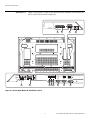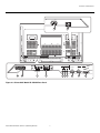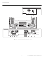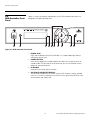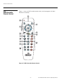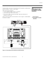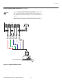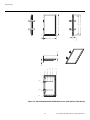
1
O W N E R ’S O P E R A T I N G M A N U A L TM SP-42DHD SP-50DHD SP-60DHD Flat Panel Plasma Display Monitor with and Digital High Definition Controller with Vivix II Technology TM TM THREE YEAR LIMITED WARRANTY For Plasma Displays Congratulations on your purchase of a Runco video product and welcome to the Runco family! We believe Runco produces “The World’s Finest Home Theater Products.” With proper installation, setup and care, you should enjoy many years of unparalleled video performance. This is a LIMITED WARRANTY as defined in the Magnuson-Moss Warranty Act. Please read it carefully and retain it with your other important documents. Y WHAT IS COVERED UNDER THE TERMS OF THIS LIMITED WARRANTY: EL IM IN A R SERVICE LABOR: Runco will pay for service labor by a Runco Authorized Service Center when needed as a result of a manufacturing defect for a period of three (3) years from the effective date of delivery to the end user (excluding the plasma glass panel). PARTS (not including plasma glass panel): Runco will provide new or rebuilt replacement parts for the parts that fail due to defects in materials or workmanship for a period of three (3) years from the effective date of delivery to the end user. Such replacement parts are then subsequently warranted for the remaining portion (if any) of the original warranty period. PLASMA GLASS PANEL: Runco will pay for service labor by a Runco Authorized Service Center when needed as a result of a manufacturing defect for a period of one (1) year from the effective date of delivery to the end user. In addition, Runco will provide new or rebuilt replacement parts for the parts that fail due to defects in materials or workmanship for a period of one (1) year from the effective date of delivery to the end user. Such replacement parts are then subsequently warranted for the remaining portion (if any) of the original warranty period. WHAT IS NOT COVERED UNDER THE TERMS OF THIS LIMITED WARRANTY: PR Image burn-in on plasma display panels is specifically excluded from coverage under this Limited Warranty. Image burn-in is the result of misuse of the product and therefore cannot be repaired under the terms of this Limited Warranty. Normal viewing material such as television/satellite broadcasts, videotape or DVDs (not put into pause for extended periods of time) will not cause damage to your display under normal conditions. Many DVD players are also equipped with screen savers for this reason. TO AVOID IMAGE RETENTION (Burn-in): Please ensure that still images are left on your plasma display panel for no more than a few minutes. Also ensure that images displayed in the 4:3 aspect ratio mode (black or gray stripes, but no picture information is present on the left and right edges of the screen) are used as infrequently as possible. This will prevent permanent image burns on your plasma display panel, which can be seen permanently under certain conditions once burn-in has occurred. The types of images to avoid include video games, still images and computer screens with stationary tool bars and icons. (This is why computers are equipped with screen savers – to prevent still images from burning into the monitor’s phosphors after being displayed continuously for an extended period of time). This Limited Warranty only covers failure due to defects in materials and workmanship that occur during normal use and does not cover normal maintenance. This Limited Warranty does not cover cabinets or any appearance items; failure resulting from accident, misuse, abuse, neglect, mishandling, misapplication, faulty or improper installation or setup adjustments; improper maintenance, alteration, improper use of any input signal; damage due to lightning or power line surges, spikes and brownouts; damage that occurs during shipping or transit; or damage that is attributed to acts of God. In the case of remote control units, damage resulting from leaking, old, damaged or improper batteries is also excluded from coverage under this Limited Warranty. CAUTION: THIS LIMITED WARRANTY ONLY COVERS RUNCO PRODUCTS PURCHASED FROM RUNCO AUTHORIZED DEALERS. ALL OTHER PRODUCTS ARE SPECIFICALLY EXCLUDED FROM COVERAGE UNDER THIS WARRANTY. PlasmaWall SP Series Owner’s Operating Manual iii MOREOVER, DAMAGE RESULTING DIRECTLY OR INDIRECTLY FROM IMPROPER INSTALLATION OR SETUP IS SPECIFICALLY EXCLUDED FROM COVERAGE UNDER THIS LIMITED WARRANTY. IT IS IMPERATIVE THAT INSTALLATION AND SETUP WORK BE PERFORMED ONLY BY AN AUTHORIZED RUNCO DEALER TO PROTECT YOUR RIGHTS UNDER THIS WARRANTY. THIS WILL ALSO ENSURE THAT YOU ENJOY THE FINE PERFORMANCE OF WHICH YOUR RUNCO PRODUCT IS CAPABLE WHEN INSTALLED AND CALIBRATED BY RUNCO AUTHORIZED PERSONNEL. RIGHTS, LIMITS AND EXCLUSIONS: EL IM IN A R Y Runco limits its obligations under any implied warranties under state laws to a period not to exceed the warranty period. There are no express warranties. Runco also excludes any obligation on its part for incidental or consequential damages related to the failure of this product to function properly. Some states do not allow limitations on how long an implied warranty lasts, and some states do not allow the exclusion or limitation of incidental or consequential damages. So the above limitations or exclusions may not apply to you. This warranty gives you specific legal rights, and you may also have other rights that vary from state to state. EFFECTIVE WARRANTY DATE: This warranty begins on the effective date of delivery to the end user. For your convenience, keep the original bill of sale as evidence of the purchase date. IMPORTANT – WARRANTY REGISTRATION: Please fill out and mail your warranty registration card. It is imperative that Runco knows how to reach you promptly if we should discover a safety problem or product update for which you must be notified. CONTACT A RUNCO AUTHORIZED SERVICE CENTER TO OBTAIN SERVICE: PR Repairs made under the terms of this Limited Warranty covering your Runco video product will be performed at the location of the product, during usual working hours, providing location of product is within normal operating distance from a Runco Authorized Service Center. In some instances it may be necessary for the product to be returned to the Runco factory for repairs. If, solely in Runco’s judgment, location of product to be repaired is beyond normal operating distance of the closest Runco Authorized Service Center, or the repair requires the unit be returned to the Runco factory, it is the owner’s responsibility to arrange for shipment of the product for repair. These arrangements must be made through the selling Runco Dealer. If this is not possible, contact Runco directly for a Return Authorization number and shipping instructions. Runco will return product transportation prepaid in the United States, unless no product defect is discovered. In that instance, shipping costs will be the responsibility of the owner. COPYRIGHT AND TRADEMARKS: © Copyright 2006 Runco International. This document contains proprietary information protected by copyright, trademark and other intellectual property laws. All rights are reserved. No part of this manual may be reproduced by any mechanical, electronic or other means, in any form, without prior written permission of the manufacturer. Reflection, Enhanced GEN3, DHD, Vivix, Virtual Cinema, CineWide, AutoScope, O-Path, CinOptx, LiveLink, CSMS, SuperOnyx and VirtualWide are trademarks of Runco International. All other trademarks and registered trademarks used in this document are the property of their respective owners. Runco International products are manufactured under one or more of the following patents: US. Patent 6755540 and Other Patents Pending. iv PlasmaWall SP Series Owner’s Operating Manual ADDITIONAL INFORMATION: To locate the name and address of the nearest Runco Authorized Service Center, or for additional information about this Limited Warranty, please call or write: EL IM IN A R Y RUNCO INTERNATIONAL, INC. Attn: Customer Service Department 2900 Faber Street Union City, CA 94587 Ph: (510) 324-7777 Fax: (510) 324-9300 Toll Free: (800) 23-RUNCO RUNCO VIDEO-PRODUCT INFORMATION RETAIN THIS INFORMATION FOR YOUR RECORDS _________________________________________________________ ________________________________________ Model Purchased Date Serial Number PR ____________________________________________________________________________________________________________ ____________________________________________________________________________________________________________ Runco Authorized Dealer Name ____________________________________________________________________________________________________________ Address ____________________________________________ __________________ ________________________ City State/Province Postal Code ____________________________________________ _________________________________________________________ Phone Fax PlasmaWall SP Series Owner’s Operating Manual v Safety Precautions Thank you for your purchase of this quality Runco product! It has been designed to provide you with the quality of video that is expected in a home theater. This manual is your guide through the menus and operation. For the best performance, please read it carefully and keep it handy for future reference. WARNING This symbol is intended to alert the user to the presence of uninsulated “dangerous voltage” within the product’s enclosure that may be of sufficient magnitude to constitute a risk of electric shock. CAUTION RISK OF ELECTRIC SHOCK DO NOT OPEN REFER SERVICING TO QUALIFIED SERVICE PERSONNEL. CAUTION This symbol is intended to alert the user to the presence of important operating and maintenance (servicing) instructions in the literature accompanying the appliance. EL IM IN A R DO NOT REMOVE COVER (OR BACK) NO USER SERVICEABLE PARTS INSIDE. Y CAUTION: TO REDUCE THE RISK OF ELECTRIC SHOCK To turn off main power, be sure to remove the plugs from power outlets. The power outlet socket should be installed as near to the equipment as possible, and should be easily accessible. WARNING TO PREVENT FIRE OR SHOCK HAZARDS, DO NOT EXPOSE THIS UNIT TO RAIN OR MOISTURE. ALSO DO NOT USE THIS UNIT’S POLARIZED PLUG WITH AN EXTENSION CORD RECEPTACLE OR OTHER OUTLETS, UNLESS THE PRONGS CAN BE FULLY INSERTED. REFRAIN FROM OPENING THE CABINET AS THERE ARE HIGH-VOLTAGE COMPONENTS INSIDE. REFER SERVICING TO QUALIFIED SERVICE PERSONNEL. WARNING PR This equipment generates, uses, and can radiate radio frequency energy and, if not installed and used in accordance with the Installation Manual, may cause harmful interference to radio communications. Operation of this equipment in a residential area may cause harmful interference, in which case the user will be required to correct the interference at his own expense. Please read and follow the safety precautions listed below to ensure the equipment is free from damage, and to ensure that no injury will occur as a result of improper use. • Do not insert any object, especially metal or liquids, into the plasma display. • Do not place any objects containing water or any other liquid on top of the plasma display. • Do not place the units in direct sunlight, near heaters or in extremely dusty or humid locations. • Do not install this system outdoors or otherwise exposed to the elements. • Do not place heavy objects on top of the plasma display. • If the power cord is damaged or frayed in any way, electrical shock and/or fire may result. Do not place objects on the power cord, and keep the cord away from heat-emitting devices. Should the power cord become damaged in any way, please contact your Runco Dealer for a replacement cord. • Do not remove the cover of the plasma display for any reason. If any problems arise with the unit, please contact a Runco Dealer or Runco International for service. Removing the covers will void the warranty. vi PlasmaWall SP Series Owner’s Operating Manual 1 Table of Contents THREE YEAR LIMITED WARRANTY ............................................................................. iii Safety Precautions ......................................................................................................... vi 1. Introduction ...............................................................................................................1 About This Manual .......................................................................................................1 Y Target Audience .....................................................................................................1 EL IM IN A R If You Have Comments About This Manual... ..........................................................1 Textual and Graphic Conventions ...........................................................................1 Using This Manual ........................................................................................................2 Description, Features and Benefits ...............................................................................3 Key Features and Benefits ......................................................................................3 Parts List ...............................................................................................................4 2. Controls and Functions ............................................................................................5 PlasmaWall at a Glance ................................................................................................5 Controls and Indicators...........................................................................................5 Connectors ............................................................................................................6 DHD Controller Front Panel ........................................................................................10 PR DHD Controller Rear Panel .........................................................................................12 Outputs ................................................................................................................12 Inputs ...................................................................................................................12 DHD Controller Remote Control .................................................................................14 3. Installation ...............................................................................................................17 Remote Control ..........................................................................................................17 Notes on Batteries ................................................................................................17 Notes on Remote Control Operation .....................................................................17 Quick Setup ...............................................................................................................19 Installation Considerations ..........................................................................................20 High-Altitude Operation ........................................................................................20 Mounting the PlasmaWall on a Wall or Table Stand ..............................................20 Ambient Light .......................................................................................................21 Ventilation .............................................................................................................21 Other Considerations ............................................................................................22 Connections to the PlasmaWall and DHD Controller ...................................................23 Connecting the PlasmaWall to the DHD Controller ................................................23 PlasmaWall SP Series Owner’s Operating Manual vii Table of Contents Connecting Source Components to the DHD Controller .......................................25 RS-232 Controller Connection ..............................................................................29 Connecting 12-Volt Trigger Outputs to External Equipment ..................................29 Cable Management ..............................................................................................30 4. Operation .................................................................................................................31 Turning on the Power .................................................................................................31 Selecting the Input Source .........................................................................................32 Setting the Computer Display Properties ....................................................................32 Y Using the On-Screen Menus ......................................................................................34 EL IM IN A R Main Menu ...........................................................................................................36 Input Source ........................................................................................................36 Aspect Ratio ........................................................................................................36 Picture .................................................................................................................38 Input Position........................................................................................................41 ISF Presets ...........................................................................................................42 Information ...........................................................................................................42 Calibration ............................................................................................................43 Service .................................................................................................................44 5. Maintenance and Troubleshooting ........................................................................49 Cleaning .....................................................................................................................49 PR Cleaning the Display Panel Body and Remote Control ..........................................49 Cleaning the Screen..............................................................................................49 Cleaning the Vents................................................................................................49 Troubleshooting Tips ..................................................................................................50 6. Serial Communications ..........................................................................................53 RS-232 Connection and Port Configuration ...............................................................53 Serial Command Syntax .............................................................................................53 7. Specifications ..........................................................................................................59 PlasmaWall Specifications ..........................................................................................59 DHD Controller Specifications ....................................................................................60 PlasmaWall Dimensions .............................................................................................61 Computer/Video Signal Compatibility .........................................................................64 APPENDIX A. PlasmaWall Service Remote Control ................................................. A-1 Overview .................................................................................................................. A-1 Service/Setup Menu ................................................................................................. A-3 Video NR (Noise Reduction)................................................................................ A-3 MPEG Filter ........................................................................................................ A-4 viii PlasmaWall SP Series Owner’s Operating Manual 1 List of Figures 2-1. PlasmaWall Front-Panel Controls and Indicators...........................................................5 2-2. PlasmaWall Model SP-42DHD Rear Panel....................................................................6 2-3. PlasmaWall Model SP-50DHD Rear Panel....................................................................7 2-4. PlasmaWall Model SP-60DHD Rear Panel....................................................................8 Y 2-5. DHD Controller Front Panel ........................................................................................10 EL IM IN A R 2-6. DHD Controller Rear Panel .........................................................................................12 2-7. DHD Controller Remote Control .................................................................................14 3-1. Available Range of the Remote Control ......................................................................17 3-2. Ventilation Requirements for Enclosure Mounting .......................................................21 3-3. Connecting the PlasmaWall to the DHD Controller .....................................................23 3-4. RS-232 Connection from the DHD Controller to the PlasmaWall ................................24 3-5. DVI Source Connections ............................................................................................25 3-6. Digital (DTV) RGB Connections...................................................................................26 3-7. Analog RGB Connections...........................................................................................27 3-8. Composite, S-Video and Component Video Connections...........................................28 3-9. RS-232 Control System Connection...........................................................................29 PR 3-10. Connecting 12-Volt Trigger Outputs .........................................................................29 3-11. Installing the Cable Ties ............................................................................................30 4-1. DHD Controller OSD Menu Structure for PlasmaWall..................................................35 4-2. Typical PLUGE Pattern for Adjusting Brightness .........................................................38 4-3. Typical Gray Bar Pattern for Adjusting Contrast ..........................................................39 4-4. Typical Color Bar Pattern for Adjusting Color Saturation and Tint................................40 4-5. Typical Test Pattern for Adjusting Sharpness..............................................................41 7-1. PlasmaWall Model SP-42DHD Dimensions (with Optional Table Stand) ......................61 7-2. PlasmaWall Model SP-50DHD Dimensions (with Optional Table Stand) ......................62 7-3. PlasmaWall Model SP-60DHD Dimensions (with Optional Table Stand) ......................63 A-1. PlasmaWall Service Remote Control ........................................................................ A-1 A-2. PlasmaWall Setup Menu .......................................................................................... A-3 PlasmaWall SP Series Owner’s Operating Manual ix List of Figures PR EL IM IN A R Y Notes: x PlasmaWall SP Series Owner’s Operating Manual 1. Introduction This Owner’s Manual describes how to install, set up and operate the Runco PlasmaWall Flat-Panel Plasma Display Monitor and DHD Controller (Model SP-42DHD, SP-50DHD or SP-60DHD). 1.1 About This Manual EL IM IN A R Y Throughout this manual, the Runco PlasmaWall Flat-Panel Plasma Display Monitor and DHD Controller are referred to collectively as the “PlasmaWall.” Except where otherwise indicated, the information in this manual applies to all three PlasmaWall models. Runco has prepared this manual to help home theater installers and end users get the most out of the PlasmaWall. Target Audience Runco has made every effort to ensure that this manual is accurate as of the date it was printed. However, because of ongoing product improvements and customer feedback, it may require updating from time to time. You can always find the latest version of this and other Runco product manuals on-line, at www.runco.com. Runco welcomes your comments about this manual. Send them to [email protected]. If You Have Comments About This Manual... Text Conventions: The following conventions are used in this manual, in order to clarify the information and instructions provided: Textual and Graphic Conventions • Remote control button identifiers are set in upper-case bold type; for example, “Press EXIT to return to the previous menu.” PR • Computer input (commands you type) and output (responses that appear on-screen) is shown in monospace (fixed-width) type; for example: “To change the aspect ratio to Anamorphic, type ANAMORPHIC <Enter>.” • All keys with functional names are initial-capped, set in bold type and enclosed in angle brackets. These keys are the following: <Enter>, <Spacebar>, <Control>, <Esc> and <Tab>. • <Enter> indicates that you may press either the RETURN or ENTER key on your computer keyboard if it has both keys. In addition to these conventions, underlining, boldface and/or italics are occasionally used to highlight important information, as in this example: Note A carriage return must be used after each command or string. PlasmaWall SP Series Owner’s Operating Manual 1 Introduction Graphic Conventions: These symbols appear in numerous places throughout the manual, to emphasize points that you must keep in mind to avoid problems with your equipment or injury: Note NOTES emphasize text with unusual importance or special significance. They also provide supplemental information. Caution CAUTIONS alert users that a given action or omitted action can degrade performance or cause a malfunction. Y TIPS highlight time-saving short cuts and helpful guidelines for using certain features. EL IM IN A R 1.2 Using This Manual Tip WARNING WARNINGS appear when a given action or omitted action can result in damage to the equipment, or possible non-fatal injury to the user. DANGER! DANGER appears when a given action can cause severe injury or death. Use the following table to locate the specific information you need in this manual. PR If you need... ... Turn to page: Information about obtaining service iv General information about the PlasmaWall Flat-Panel Plasma Display Monitor and DHD Controller 3 Installation instructions 17 First-time configuration instructions 31 Advanced configuration instructions 43 Troubleshooting tips 50 Specifications for the PlasmaWall Flat-Panel Plasma Display Monitor and DHD Controller 59 2 PlasmaWall SP Series Owner’s Operating Manual Introduction The PlasmaWall SP Series flat-panel plasma monitor brings outstanding picture quality to its size category with true, high-definition native resolution of up to 1365 x 768 (1024 x 768 on the Model SP-42DHD) for no-compromise viewing of any video source. 1.3 Description, Features and Benefits The PlasmaWall is supplied with Runco’s next-generation, Digital High Definition (DHD) Controller, featuring advanced Vivix II™ processing. This controller produces stunning video imagery, elevating even standard NTSC material to near high-definition levels. Y Multiple aspect ratio control includes Runco’s VirtualWide™ for viewing 4:3 material in widescreen with no loss of picture quality. The DHD provides for a pure digital signal path from input to output, making this system ready for Runco’s exclusive LiveLink™ DVI cable solution to preserve HD signal quality over long runs. EL IM IN A R The PlasmaWall’s black level performance and shadow detail capability have been enhanced with Active Gray Scale Rendering to provide smoother transitions from dark to light, resulting in richly detailed textures even in shadowy scenes. The PlasmaWall is easily integrated into custom installation systems. Both RS-232C and IR control interfaces are incorporated for simple automation. Its profile is less than 5-1/2 inches thin for wall-mounting simplicity. The PlasmaWall offers these key features and benefits: • 16:9 Native Resolution: 1024 x 768 (Model SP-42DHD) or 1365 x 768 (Models SP-50DHD and SP-60DHD) • Multiple Aspect Ratios with VirtualWide™ Mode • 160 degree horizontal/vertical viewing angle • Accepts all DTV formats (via outboard decoder), including 1080i, 720p and 480p • Less than 5-1/2 inches deep PR • Two DVI Inputs (on DHD Controller) with High-bandwidth Digital Content Protection (HDCP) • Exceptional detail and artifact-free video enhancement • Vivix™ video processing with 3:2 film detection circuitry PlasmaWall SP Series Owner’s Operating Manual 3 Key Features and Benefits Introduction Parts List ➤ Your PlasmaWall is shipped with the following items. If any items are missing or damaged, please contact your Runco dealer or Runco Customer Service at (800) 23-RUNCO. • PlasmaWall Flat-Panel Plasma Display Monitor and DHD Controller • AC Power Cords (2) • Remote Control Unit and two (2), AAA-size batteries • Service Remote Control Unit and two (2), AA-size batteries • RJ-11 Telephone Cable, 50 feet (15.24 meters) • Serial Port Adapter, RJ-11 Female to DB-9 Female • Rack-mount hardware for the DHD Controller Y • Cleaning Cloth • Cable Ties (2) EL IM IN A R • Warranty information and registration card • PlasmaWall SP Series Owner’s Operating Manual (this document) Optional Accessories: • Wall Mount Kit • Table Stand PR • LiveLink™ DVI Cabling System 4 PlasmaWall SP Series Owner’s Operating Manual 2. Controls and Functions 2.1 PlasmaWall at a Glance Controls and Indicators EL IM IN A R Y Figure 2-1 shows the PlasmaWall front-panel controls and indicators. 4 (SP-42DHD/SP-50DHD) 4 (SP-60DHD) 1 PR 2 3 Figure 2-1. PlasmaWall Front-Panel Controls and Indicators 1. DISPLAY STAND Optional accessory for tabletop installations. 2. REMOTE CONTROL SENSOR Receives the signals from the remote control. 3. STANDBY/ON INDICATOR - Lights green to indicate normal operation; - Lights red to indicate that the PlasmaWall is in standby mode; - Flashes green or red (twice per second) to indicate an error condition. 4. HANDLES ALWAYS use the handles when carrying the unit. PlasmaWall SP Series Owner’s Operating Manual 5 Controls and Functions Connectors ➤ Figure 2-2 and Figure 2-3 show the rear-panel connector and power switch locations on the SP-42DHD and SP-50DHD respectively. 10 11 12 PR EL IM IN A R Y 9 IN OUT COMBINATION 1 OUTPUT INPUT1 INPUT2 AUDIO RS-232C 2 INPUT1 ANALOG RGB OUT (D-Sub) ANALOG RGB IN (D-Sub) 6 7 INPUT2 DIGITAL RGB (DVI-D) AUDIO AUDIO 3 4 5 8 Figure 2-2. PlasmaWall Model SP-42DHD Rear Panel 6 PlasmaWall SP Series Owner’s Operating Manual Controls and Functions 12 EL IM IN A R Y 11 IN OUT OUTPUT COMBINATION 10 PR 9 1 AUDIO RS-232C 2 7 INPUT1 ANALOG RGB OUT (D-Sub) ANALOG RGB IN (D-Sub) INPUT2 DIGITAL RGB (DVI-D) AUDIO AUDIO 3 4 5 Figure 2-3. PlasmaWall Model SP-50DHD Rear Panel PlasmaWall SP Series Owner’s Operating Manual INPUT1 INPUT2 6 7 8 Controls and Functions 12 IN EL IM IN A R Y 11 OUT OUTPUT INPUT1 INPUT1 INPUT2 ANALOG RGB OUT (D-Sub) PR 1 AUDIO RS-232C COMBINATION 9 10 INPUT2 DIGITAL RGB (DVI-D) AUDIO AUDIO 3 4 5 2 ANALOG RGB IN (D-Sub) 6 7 8 Figure 2-4. PlasmaWall Model SP-60DHD Rear Panel 8 PlasmaWall SP Series Owner’s Operating Manual Controls and Functions 1. COMBINATION IN/OUT Not used. 2. RS-232C (9-pin, male D-Sub) Connect the RS-232 OUT port on the DHD Controller to this input. 3. AUDIO (OUTPUT) (3.5-mm stereo mini jack) Not used with this model. 4. AUDIO (INPUT 1) (3.5-mm stereo mini jack) Not used with this model. Connect the audio outputs from your sources to an external audio receiver. Y 5. AUDIO (INPUT 2) (3.5-mm stereo mini jack) Not used with this model. Connect the audio outputs from your sources to an external audio receiver. Note EL IM IN A R 6. ANALOG RGB OUT (INPUT 1) (15-pin D-Sub) If desired, connect this output to the RGB input of a second display device. This output is not active when the PlasmaWall is off or in standby mode. 7. ANALOG RGB IN (INPUT 1) (15-pin D-Sub) Connect the RGBHV (5xBNC) output from the DHD Controller here. 8. DIGITAL RGB (INPUT 2) (DVI-D) HDCP-compliant digital video input. Connect the DVI output from the DHD Controller to this input. 9. EXTERNAL SPEAKER OUTPUT (RIGHT) Not used. Connect speakers to an external audio amplifier/receiver. PR 10. EXTERNAL SPEAKER OUTPUT (LEFT) Not used. Connect speakers to an external audio amplifier/receiver. 11. POWER INPUT (100 to 240 VAC) Connect the PlasmaWall to power here, using the included power cord. 12. MAIN POWER SWITCH Connects or disconnects the PlasmaWall from the AC power source. PlasmaWall SP Series Owner’s Operating Manual 9 Controls and Functions 2.2 DHD Controller Front Panel 1 2 EL IM IN A R Y Figure 2-5 shows the controls and indicators on the DHD Controller front panel; the paragraphs that follow describe them. 3 4 5 6 7 8 9 10 Figure 2-5. DHD Controller Front Panel 1. RUNCO ICON Lights red to indicate that the DHD Controller is in standby mode; lights blue to indicate that the unit is on. PR 2. POWER BUTTON Press once to toggle from standby mode to on mode. Press it again to return to standby mode. For a discrete on or off command, you can use the direct access buttons on the remote control. 3. IR SENSOR Receives IR commands from the remote. 4. VACUUM FLUORESCENT DISPLAY Can be used instead of the On-Screen Display (OSD). Displays currently-selected menu or – if no menu is selected – the current source, signal format (NTSC or PAL), input resolution and aspect ratio. 10 PlasmaWall SP Series Owner’s Operating Manual Controls and Functions 5. UP BUTTON Use to direct-select aspect ratios or move the menu cursor up in the OSD. When no menu is present on-screen, the UP button toggles through aspect ratios in the following order: Anamorphic - Standard (4:3) - Letterbox - VirtualWide - Cinema (For more information about aspect ratios, refer to Table 4-1.) EL IM IN A R 7. ENTER BUTTON When an item is highlighted on the OSD, press ENTER to select it. Y 6. LEFT BUTTON Used to direct-select inputs or move the menu cursor left in the OSD. When no menu is present on-screen, the LEFT button toggles through the different sources, in this order: HD Pass Thru 2 - HD Pass Thru 1 - DVI 2 - DVI 1 - HD/RGB2 - HD/RGB1 Component SD - S-Video 2 - S-Video 1 - Composite 8. DOWN BUTTON Use to direct-select aspect ratios or move the menu cursor down in the OSD. When no menu is present on-screen, the DOWN button toggles through the different aspect ratios, in this order: Cinema - VirtualWide - Letterbox - Standard (4:3) - Anamorphic 9. RIGHT BUTTON Used to direct-select inputs or move the menu cursor right in the OSD. When no menu is present on-screen, the RIGHT button toggles through the different sources, in this order: Composite - S-Video 1 - S-Video 2 - Component SD - HD/RGB 1 - HD/RGB 2 - DVI 1 - DVI 2 - HD Pass Thru 1 - HD Pass Thru 2 PR 10. MENU BUTTON Pressing the MENU button brings up the main menu. Also, if you are in an adjustment mode or function, pressing MENU brings the menu back one level. PlasmaWall SP Series Owner’s Operating Manual 11 Controls and Functions 2.3 DHD Controller Rear Panel Figure 2-6 shows the rear connector panel on the DHD Controller. 8 4 10 SYSTEM CONTROL INTERFACE R/Pr G/Y B/Pb RISK OF ELECTRIC SHOCK DO NOT OPEN H V 2 OUTPUTS HD2 B/Pb Video Processor / Controller G/Y B/Pb H V EL IM IN A R R/Pr SDI V 1 SHOCK, DO NOT REMOVE COVER. NO USERSERVICEABLE PARTS INSIDE. REFER SERVICING TO QUALIFIED SERVICE CENTER. H/V DVI Out 2 DVI 1 DVI 2 Option 3 Pb Pr Component Video 5 Y Video 6 7 IR 3 Y 1 H CAUTION: TO REDUCE THE RISK OF ELECTRIC HD1 Model G/Y ! AVIS: RISQUE DE CHOC ELECTRIQUE-NE PAS OUVRIR TRIGGERS Runco International Union City, CA R/Pr CAUTION INPUTS Serial No WARNING: TO REDUCE THE RISK OF FIRE OR ELECTRIC SHOCK, DO NOT EXPOSE THIS APPLIANCE TO RAIN OR MOISTURE. S-Video 1 100-230VAC 50-60 Hz, 165 Watts Max S-Video 2 RS-232 Out 9 RS-232 Control 11 Made In USA 12 13 14 Figure 2-6. DHD Controller Rear Panel Outputs ➤ 1. ANALOG OUTPUTS (RGBHV) Connect these to the ANALOG RGB IN input of the PlasmaWall, using a 5 x BNC-to-VGA breakout cable. 2. DVI OUT Connect this to the DIGITAL RGB (DVI-D) input on the PlasmaWall. PR Inputs ➤ 3. DVI 1 / DVI 2 (Digital) Two, HDCP-compliant digital video inputs for connecting a DVD player or HD tuner with a DVI or HDMI output. 4. HD1 / HD2 (5 x Analog BNCs) Two inputs (five BNCs per input) for connecting either RGB or component high-definition television signals. The DHD Controller automatically detects the signal format: RGB(HV) or YPrPb, 480p, 720p, 480i, 576i or 1080i. 5. COMPONENT VIDEO (RCA connectors) Standard Definition (480i/576i) Component (YPrPb) input. This is the input for component video from sources such as DVD players. Tip For best results, do not run your DVD player in progressive mode. 12 PlasmaWall SP Series Owner’s Operating Manual Controls and Functions 6. COMPOSITE VIDEO INPUT Standard composite video input for connecting a VCR, camcorder, laser disc player or other composite video source. 7. S-VIDEO 1 / S-VIDEO 2 Two, standard S-Video inputs for connecting a DVD player, satellite receiver or Super VHS (S-VHS) VCR. 8. 12-VOLT (750 mA) TRIGGER OUTPUTS Connection for up to three (3), 12-volt trigger-controlled devices. Y 9. RS-232 OUTPUT (6-Wire, RJ-11 jack) Connect this to the RS-232C input of the PlasmaWall, using the supplied serial port adapter and communication cable. Note EL IM IN A R 10. IR Wired input from an external remote control or infrared receiver. It is a 3.5-mm, mini phono jack, wired as follows: Ring = +5V Tip = IR Input Sleeve = Ground When an external remote control or infrared receiver is connected to the wired IR input, the IR sensor on the front of the DHD Controller is disabled. 11. RS-232 CONTROL PORT A female, 9-pin D-sub connector for interfacing with a PC or home theater automation/control system. 12. POWER INPUT (100 to 240 VAC) Connect the DHD Controller to power here. PR 13. MAIN AC FUSE This is the main AC input fuse (5mm x 20mm, 500 mA, 250V slow-blow). 14. MAIN POWER SWITCH Disconnects or applies power to the DHD Controller. PlasmaWall SP Series Owner’s Operating Manual 13 Controls and Functions 2.4 DHD Controller Remote Control Figure 2-7 shows the DHD Controller remote control, and the paragraphs that follow describe its functionality. 2 Y 1 3 EL IM IN A R 4 6 5 8 7 10 11 9 PR 12 13 Figure 2-7. DHD Controller Remote Control 14 PlasmaWall SP Series Owner’s Operating Manual Controls and Functions 1. IR OUTPUT INDICATOR Lights when a button is pressed to indicate that an IR signal is being transmitted. 2. ON / OFF Press to turn the PlasmaWall on or off. 3. ENTER Press to select a highlighted menu item or confirm a changed setting. 4. Cursor Keys ( , , , ) Use these buttons to select items or settings, adjust settings or switch display patterns. EL IM IN A R Y When no menus are present on-screen, the UP and DOWN buttons toggle through the available aspect ratios, in this order: UP Button = Anamorphic - Standard (4:3) - Letterbox - VirtualWide - Cinema DOWN Button = Cinema - VirtualWide - Letterbox - Standard (4:3) - Anamorphic Likewise, the LEFT and RIGHT buttons toggle through the different source inputs, in this order: LEFT Button = HD Pass Thru 2 - HD Pass Thru 1 - DVI 2 - DVI 1 - HD/RGB2 HD/RGB 1 - Component SD - S-Video 2 - S-Video 1 - Composite RIGHT Button = Composite - S-Video 1 - S-Video 2 - Component SD - HD/RGB 1 HD/RGB 2 - DVI 1 - DVI 2 - HD Pass Thru 1 - HD Pass Thru 2 5. LIGHT Press to illuminate the buttons. 6. MENU Press this button to access the OSD controls, or to exit the current menu and return to the previous one. PR 7. VIDEO (1) Press to select Composite video input as the source or to enter the numeric character “1.” 8. COMP (Component) (2) Press to select Component SD (480i/576i) video input as the source or to enter the numeric character “2.” PlasmaWall SP Series Owner’s Operating Manual 15 Controls and Functions 9. Aspect Ratio Selection Buttons Use the red buttons to select an aspect ratio directly or to enter numeric characters, as follows: ANA (Anamorphic) (3) For viewing 16:9 DVDs or HDTV programs in their native aspect ratio. 4X3 (Standard 4:3) (6) Scales the input signal to fit 4:3 display mode in the center of the screen. Y LETBOX (Letterbox) (9) For viewing LaserDisc movies or non-anamorphic DVDs on a 16:9 screen. EL IM IN A R V-WIDE (VirtualWide) Enlarges a 4:3 image horizontally in a NON-linear fashion to fit 16:9 full screen display. CINEMA For viewing 2.35:1 source material on a 1.78:1 (16:9) screen. The upper and lower portions are masked. SVC Not used. 10. S-VID 1 (4) / S-VID 2 (5) (S-Video) Press to select an S-Video input or to enter the numeric character “4” or “5.” 11. HD 1 (7) / HD 2 (8) Press to select a HD (RGBHV or YPbPr component) input or to enter the numeric character “7” or “8.” PR 12. DVI 1 / DVI 2 (0) Press to select a Digital Video input. Press DVI2 to enter the numeric character “0.” 13. Memory Preset Buttons: ISF NIGHT Press to recall settings for the current input from the “ISF Night” memory preset. ISF DAY Press to recall settings for the current input from the “ISF Day” memory preset. CUST 1 Press to recall settings for the current input from the “Custom 1” memory preset. CUST 2 Press to recall settings for the current input from the “Custom 2” memory preset. 16 PlasmaWall SP Series Owner’s Operating Manual 3. Installation 3.1 Remote Control To install batteries in the remote control: EL IM IN A R Y 1. Press down the tab on the cover and pull the cover in the direction of the arrow. 2. Insert the included batteries. Ensure that the polarities correctly match the and markings inside the battery compartment. 3. Insert the lower tab of the cover into the opening, and press down the cover until it clicks in place. • When installing batteries, make sure that the battery polarities are correct. Notes on Batteries • Do not mix an old battery with a new one or different types of batteries. PR • If you will not use the remote control for a long time, remove the batteries to avoid damage from battery leakage. The remote control can be used to control the PlasmaWall within the ranges shown in Figure 3-1. Approx. 7m /23ft Figure 3-1. Available Range of the Remote Control PlasmaWall SP Series Owner’s Operating Manual 17 Notes on Remote Control Operation Installation • Do not drop the remote control or expose it to moisture or high temperature. • The remote control may malfunction under a fluorescent lamp. If that occurs, move the plasma display away from the fluorescent lamp. • Make sure that there is nothing obstructing the infrared beam between the remote control and the IR receiver on the plasma display. Note The signal from the remote control can be reflected by walls or other surfaces. Y • If the effective range of the remote control decreases, or it stops working, replace the batteries with new ones. PR EL IM IN A R • Ambient conditions may possibly impede the operation of the remote control. If this happens, point the remote control at the plasma display and repeat the operation. 18 PlasmaWall SP Series Owner’s Operating Manual Installation Table 3-1 gives a quick overview of the PlasmaWall installation process. The sections following this one provide detailed instructions. Note Installation should be performed by a qualified custom video installation specialist. For Details, refer to page... Procedure EL IM IN A R Step Y Table 3-1. Installation Overview Mount the PlasmaWall on a wall or table stand 20 2 Connect the DHD Controller to the PlasmaWall 23 3 Connect signal sources to the DHD Controller 25 4 Connect external controller to DHD Controller RS-232 port (optional) 29 5 Apply power to the PlasmaWall 31 6 If using the PlasmaWall with a computer, adjust computer display properties 32 7 Display calibration: adjust the following for each input; save settings when finished: • Aspect ratio • Brightness • Contrast • Color level • Tint • Sharpness 36 through 44 PR 1 PlasmaWall SP Series Owner’s Operating Manual 19 3.2 Quick Setup Installation 3.3 Installation Considerations Proper installation of your PlasmaWall will ensure the highest possible picture quality. Whether you are installing the PlasmaWall temporarily or permanently, you should take the following into account to ensure that it performs optimally. High-Altitude Operation ➤ Due to the design of all plasma glass panels made by every manufacturer, and the interaction between ambient air pressure and the plasma gases contained inside of the panel, reliable operation of your plasma display cannot be assured during operation at certain high-altitude locations. EL IM IN A R Y Runco has found this plasma monitor to operate reliably at altitudes of up to 6000 MSL (mean sea level). At elevations higher than this, each panel may react differently, depending upon the altitude, air pressure, humidity and other meteorological factors. For this reason, Runco International makes no warranties or claims as to the reliable operation of the SP-42DHD at altitudes greater than 6000 feet above sea level. If you are planning to use this product at a location above 6000 feet, please contact Runco technical support for further information. Mounting the PlasmaWall ➤ on a Wall or Table Stand To install the PlasmaWall, you will need either an optional table stand or wall-mounting kit. The PlasmaWall cannot be installed on its own. If you do decide to wall-mount the PlasmaWall, ensure that the wall-mount bracket is installed according to the instructions included with it. The wall must be capable of supporting a redundant weight factor three (3) times the weight of the display, or be reinforced. Runco recommends that this be done by a custom installation specialist. PR Note Use only a Runco-approved wall-mount kit or table stand that is specifically designed for your display. You can attach your optional mounts or stand to the PlasmaWall in either of two ways: • While it is upright. 20 PlasmaWall SP Series Owner’s Operating Manual Installation • As it lies flat with the screen face down. Place the protective sheet, which was wrapped around the plasma monitor when it was packaged, between the screen and your work surface to avoid scratching or otherwise damaging the screen surface. Ambient Light EL IM IN A R Y In general, minimize or eliminate light sources directed at the display. Contrast ratio in your images will be noticeably reduced if light directly strikes the display, such as when a shaft of light from a window or floodlight falls on the image. Images may then appear washed out and less vibrant. 50mm (2") PR 50mm (2") 50mm (2") Wall 50mm (2") If you are mounting the PlasmaWall in an enclosure, leave at least 2 inches (50 mm) of space on all sides between it and surrounding objects, as shown in Figure 3-2. This allows heat to disperse, maintaining the proper operating temperature. Wall 50mm (2") Figure 3-2. Ventilation Requirements for Enclosure Mounting PlasmaWall SP Series Owner’s Operating Manual 21 Ventilation Installation Other Considerations ➤ Other considerations and tips that can help improve your installation, avoid damage and prolong operating life: • Keep the ambient temperature constant and below 35°C (95°F). Keep the display away from heating and/or air conditioning vents. Changes in temperature may cause drifts in the display circuitry, which may affect performance. • Keep the PlasmaWall away from devices that radiate electromagnetic energy such as motors and transformers. Common sources of these include slide projectors, speakers, power amplifiers and elevators. • Handle the unit carefully when installing or carrying it. Use the built-in handles; DO NOT touch or hold the screen face. Y • Set the unit away from heat, excessive dust, and direct sunlight. EL IM IN A R • Protect the inside of the unit from liquids and small metal objects. In case of accident, unplug the power cord and have it serviced by an authorized Service Center. • Do not hit or scratch the panel surface as this causes flaws on the surface of the screen. • For correct installation and mounting it is strongly recommended to use a trained, authorized dealer. PR • To avoid sulfurization, it is strongly recommended not to place the unit in a dressing room in a public bath or hot spring bath. 22 PlasmaWall SP Series Owner’s Operating Manual Installation Proceed as follows to connect the PlasmaWall to the DHD Controller, your video sources, external controller(s) – if present – and AC power. When connecting your equipment: • Turn off all equipment before making any connections. 3.4 Connections to the PlasmaWall and DHD Controller • Use the correct signal cables for each source. • Ensure that the cables are securely connected. Tighten the thumbscrews on connectors that have them. EL IM IN A R Y Connect the DHD Controller to the PlasmaWall as shown in Figure 3-3 and described in the sections that follow. DHD Controller SYSTEM CONTROL INTERFACE CAUTION INPUTS Serial No R/Pr G/Y B/Pb RISK OF ELECTRIC SHOCK DO NOT OPEN H V ! AVIS: RISQUE DE CHOC ELECTRIQUE-NE PAS OUVRIR TRIGGERS Runco International Union City, CA CAUTION: TO REDUCE THE RISK OF ELECTRIC SHOCK, DO NOT REMOVE COVER. NO USERSERVICEABLE PARTS INSIDE. REFER SERVICING TO QUALIFIED SERVICE CENTER. HD1 1 2 IR 3 Model OUTPUTS R/Pr G/Y HD2 B/Pb Video Processor / Controller WARNING: TO REDUCE THE RISK OF FIRE R/Pr G/Y B/Pb H OR ELECTRIC SHOCK, DO NOT EXPOSE THIS APPLIANCE TO RAIN OR MOISTURE. V SDI Pb Pr S-Video 1 Y 100-230VAC 50-60 Hz, 165 Watts Max H V DVI Out DVI 1 DVI 2 Option Component Video Video S-Video 2 RS-232 Out RS-232 Control Made In USA RS-232 OUT DVI OUT PR RGB-HV OUT H/V IN OUT OUTPUT INPUT1 INPUT2 INPUT1 ANALOG RGB OUT (D-Sub) COMBINATION AUDIO RS-232C RS-232C INPUT2 ANALOG RGB IN (D-Sub) DIGITAL RGB (DVI-D) AUDIO AUDIO DIGITAL RGB (INPUT 2) ANALOG RGB IN (INPUT 1) Figure 3-3. Connecting the PlasmaWall to the DHD Controller PlasmaWall SP Series Owner’s Operating Manual 23 Connecting the PlasmaWall to the DHD Controller Installation Digital Video Connection: The PlasmaWall has a DVI input, labeled DIGITAL RGB. Connect the DVI output from the DHD Controller to this input, using a standard DVI cable. RGBHV Connection: Connect the RGBHV output from the DHD Controller to the ANALOG RGB IN input on the PlasmaWall. Use a standard, RGBHV breakout cable with five BNC connectors at the DHD end and a 15-pin, D-sub male connector at the PlasmaWall end. XMT DATA RCV DATA EL IM IN A R 4 Y RS-232 Connection: Connect the RS-232 output from the DHD Controller to the RS-232C input on the PlasmaWall. Use a standard, modular telephone cable with RJ11 plugs at both ends. On the PlasmaWall end, use the provided RJ11-to-DB9 adapter. This adapter is wired as shown in Figure 3-4. 3 To/From DHD Controller 2, 5 RCV DATA XMT DATA SIG GND SIG GND REQUEST TO SEND CLEAR TO SEND NO CONNECTION 1, 6 3 2 PlasmaWall 1 5 5 6 9 8 7 RS-232C 1, 9 DB-9 Female PR RJ-11 Male Figure 3-4. RS-232 Connection from the DHD Controller to the PlasmaWall 24 PlasmaWall SP Series Owner’s Operating Manual Installation Connect your video sources to the DHD Controller as shown and described in the sections that follow. DVI Connections: See Figure 3-5. Use the DVI inputs whenever possible. This ensures the highest video quality because the signal is carried in the digital domain throughout the entire signal path, from source component output into the display. Tip INPUTS G/Y B/Pb H V TRIGGERS HD1 2 3 IR EL IM IN A R 1 Y R/Pr HD2 R/Pr G/Y B/Pb H V Pb DVI 2 Component Video Y S-Video 1 Video S-Video 2 DVI Source (DVD Player or HD Tuner with HDMI or DVI out) PR DVI 1 Pr Figure 3-5. DVI Source Connections PlasmaWall SP Series Owner’s Operating Manual 25 Connecting Source Components to the DHD Controller Installation Digital (DTV) RGB Connections: See Figure 3-6. R/Pr INPUTS B/Pb G/Y H V TRIGGERS HD1 1 2 3 HD2 R/Pr G/Y B/Pb H V DVI 1 EL IM IN A R DVI 2 Y S-Video 1 Horiz Pr Y Component Video Video S-Video 2 Vert PR Red/Pr Green/Y Blue/Pb Pb DTV or Progressive Component (YPbPr) Source Figure 3-6. Digital (DTV) RGB Connections 26 PlasmaWall SP Series Owner’s Operating Manual Installation Analog (Computer) RGB Connections: See Figure 3-7. 1. Refer to Computer/Video Signal Compatibility on page 64 for a list of computer signals compatible with the PlasmaWall. Use with signals other than those listed may cause some functions not to work. Note 2. Some Macintosh computers may require a Macintosh video adapter. Contact your nearest authorized service center or dealer. G/Y INPUTS B/Pb H V Y R/Pr TRIGGERS HD1 2 3 EL IM IN A R 1 HD2 R/Pr G/Y B/Pb H V S-Video 1 DVI 1 DVI 2 Y Pr Component Video Video S-Video 2 Vert PR Red Green Blue Horiz Pb Personal Computer Figure 3-7. Analog RGB Connections PlasmaWall SP Series Owner’s Operating Manual 27 Installation Composite/S-Video/Component Video Connections: See Figure 3-8. R/Pr G/Y INPUTS B/Pb H V TRIGGERS HD1 1 2 3 HD2 R/Pr G/Y B/Pb H V S-Video 1 Pb DVI 2 Y Pr Component Video Video S-Video 2 EL IM IN A R Y DVI 1 PR Pb Pr Y DVD Player, VCR, Satellite Receiver, Laser Disc etc. Figure 3-8. Composite, S-Video and Component Video Connections 28 PlasmaWall SP Series Owner’s Operating Manual Installation Use a standard, 9-pin RS-232 cable to connect a PC or home theater control/automation system (if present) to the RS-232 Control port on the DHD Controller; see Figure 3-9. RS-232 Controller Connection For more information about using this connection, refer to Serial Communications on page 53. 5 4 3 1 2 TRIGGERS 1 Component Video 8 S-Video 1 Y Video S-Video 2 RS-232 Out 7 6 2 Transmit Data 3 Receive Data 5 Ground Y Pr 9 IR 3 RS-232 Control EL IM IN A R Pb 2 (none of the other pins are used) to Automation/ Control System or PC Figure 3-9. RS-232 Control System Connection PR If your home theater contains equipment that responds to 12-Volt triggers, connect it to the 12-Volt trigger outputs as shown in Figure 3-10. Pb Pr Component Video TRIGGERS 1 2 3 IR S-Video 1 Y Video S-Video 2 RS-232 Out RS-232 Control 3.5-mm mini plug to 12-Volt trigger-activated equipment Sleeve = Ground Tip = +12V Figure 3-10. Connecting 12-Volt Trigger Outputs PlasmaWall SP Series Owner’s Operating Manual 29 Connecting 12-Volt Trigger Outputs to External Equipment Installation Cable Management ➤ To minimize cable clutter, you can use the cable ties provided with the PlasmaWall to bundle the video, control and power cables at the back of the display. Install the cable ties as shown in Figure 3-11. Cables can be routed to the right or left. Note Do not allow excessive stress to be placed on the ends of cables. PR EL IM IN A R Y * As viewed from the rear of the display. Figure 3-11. Installing the Cable Ties 30 PlasmaWall SP Series Owner’s Operating Manual 4. Operation 4.1 Turning on the Power 1. Turn on your source components. EL IM IN A R Y 2. Plug the female end of the power cord into the AC receptacle on the rear of the PlasmaWall. Connect the other end to your AC power source. 3. Similarly connect the DHD Controller to a nearby AC outlet. 4. Set the main power switch at the rear of the PlasmaWall (see Figure 2-2) to the “on” position. Its power indicator lights red. 5. Set the main power switch at the rear of the DHD Controller (see Figure 2-6) to the “on” position. 6. Press the ON button on the remote control to turn on the DHD Controller and PlasmaWall (or press the power button on the front of the DHD Controller). The power indicator on the DHD Controller lights solid blue. PR 7. After a brief warm-up period (approximately 10 seconds), the PlasmaWall will display an image. PlasmaWall SP Series Owner’s Operating Manual 31 Operation 4.2 Selecting the Input Source By default, the PlasmaWall is configured to display the signal received on its RGBHV (ANALOG RGB IN) input. To use the DVI-D (DIGITAL RGB) input instead: 1. Press MENU and enter the Service Menu passcode. Note You must enter a passcode to access the Service menu. 2. Select Service from the Main Menu. 4.3 Setting the Computer Display Properties to select DVI/HDMI, then press ENTER. EL IM IN A R 4. Press Y 3. Select Display Device from the Service Menu. To maximize image quality when using the PlasmaWall with a personal computer, you may need to adjust the display properties of your computer’s video card. To do this on a Microsoft® Windows®-based PC: PR 1. Choose Settings from the Windows Start Menu and click on “Control Panel.” 2. Double click on the Display icon. 3. Click the Settings tab on the display dialog box. 4. Adjust the resolution to 1024x768 pixels. 32 PlasmaWall SP Series Owner’s Operating Manual Operation Note EL IM IN A R Y 5. Click the Advanced button and click the Monitor tab on the dialog box. Set the vertical frequency to 60Hz and click OK. 1. The native resolution of the SP-42DHD is 1024 x 768; the native resolution of the SP-50DHD and SP-60DHD is 1365 x 768. Other horizontal or vertical resolutions may be scaled upward or downward to fit the display. 2. With most computers, you can get the best picture at 1024 x 768 @ 60Hz. 3. For best results when using a computer, set the input on the DHD Controller to HD Pass Thru 1 or HD Pass Thru 2, depending on which RGB/HD input you are using. To prevent image retention (burn) on your display, ALWAYS use a screen saver and set it to the shortest possible time. PR WARNING PlasmaWall SP Series Owner’s Operating Manual 33 Operation 4.4 Using the On-Screen Menus Press the MENU button on either the remote control or the DHD Controller front panel to display the Main Menu. To select a menu item, use the UP ( ) and DOWN ( ) buttons on either the remote control or the DHD Controller front panel to highlight it. Press ENTER to confirm your selection. PR EL IM IN A R Y The PlasmaWall OSD menus are arranged hierarchically, as shown in Figure 4-1. Depending on the selected input source and signal characteristics, some menu options may not be available. 34 PlasmaWall SP Series Owner’s Operating Manual Operation Picture Input Position ISF Presets Information (read-only) PR Test Video ISF Night - Input Image ISF Night - Input Color Y Aspect Ratio ISF Night - Display Color EL IM IN A R Input Source Composite S-Video 1 S-Video 2 Component SD HD/RGB 1 HD/RGB 2 DVI 1 DVI 2 HD Pass Thru 1/ HD Pass Thru 2 (available only when Display Device Input Source = RGB) Anamorphic Standard 4:3 Letterbox VirtualWide Cinema Brightness Contrast Color Tint Sharpness Left/Right Up/Down Width Height Overscan Recall ISF Night Recall ISF Day Recall/Save Custom 1 Recall/Save Custom 2 Reset Custom 1 & 2 to Factory Default Serial Number Hardware Firmware Date Input Names Remote Control Analog Out Mode Display Device Service HD Format Triggers Miscellaneous Resolution Grey Bars 1 Grey Bars 2 Color Bars 1 Color Bars 2 Rename, Restore or Save Primary Secondary RGB--, RGB++ or RGBS Input Source Configure HD/RGB 1 HD/RGB 2 ADC Bandwidth YPbPr Input Resolution 1 / 2 / 3 / Save Language Menu Mode Timeout Side Bar Color Film Mode (SD src. only) 800x600 ... 1400x1050 480p ... 720p ... 1080i Calibration ISF Day - Input Image ISF Day - Input Color Save ISF Settings Output Shift Splash Configure OSD Position RGB or DVI/HDMI Left/Right Up/Down Width Height Auto, RGB or YUV Auto, 75 MHz, 150 MHz or 300 MHz Auto, 480i/p, 576i/p, 720p or 1080i (currently, English only) System Reset Restore Saved Settings Figure 4-1. DHD Controller OSD Menu Structure for PlasmaWall PlasmaWall SP Series Owner’s Operating Manual ISF Day - Display Color 35 Gain Offset Color Temp. (available only when Display Device Input Source = RGB) Brightness Contrast Color Tint Sharpness Gain Offset Chroma Delay Phase Noise Filter Gain Offset Color Temp. (available only when Display Device Input Source = RGB) Brightness Contrast Color Tint Sharpness Gain Offset Chroma Delay Phase Noise Filter Back / Confirm Left/Right Up/Down Width Height Save Owner Name ISF Calibrated ISF Other Splash Enable Operation Main Menu ➤ The Main Menu is the starting point for accessing all display functions. (The Calibration and Service menus are hidden and not accessible until you enter a passcode.) Runco Video Input Source Aspect Ratio Picture Input Position ISF Presets Information Calibration Input Source > Composite S-Video 1 S-Video 2 Component SD HD/RGB 1 HD/RGB 2 DVI 1 DVI 2 HD Pass Thru 1 PR HD Pass Thru 2 Aspect Ratio ➤ Aspect Ratio 7 Anamorphic Standard 4:3 From the Main Menu, select Input Source to choose a video signal source. EL IM IN A R Input Source ➤ Y Service The active source is indicated by an arrow (>) to its left; in the example at left, Composite is the active source. Note 1. HD Pass Thru 1 and HD Pass Thru 2 are available only when the Display Device Input Source is set to RGB; refer to Display Device on page 46. 2. Selecting HD Pass Thru 1 or HD Pass Thru 2 loops the HD/RGB 1 or HD/RGB 2 input signal respectively to the RGB output. This prevents display of the on-screen menus. To switch from HD Pass Thru 1 or 2 to another source, use the direct access buttons on the remote control, or the left- or right-arrow buttons on the DHD Controller. 3. If the DVI 1 or DVI 2 input is active and the input signal is HDCP-encrypted, the RGBHV output of the DHD Controller is disabled. To change the aspect ratio (size and shape) of the projected image, select Aspect Ratio from the Main Menu and press ENTER. Select the appropriate aspect ratio for your screen size and the type of program material being viewed; refer to Table 4-1. The currently-selected aspect ratio is indicated by a “7” to its left; in the example at left, Anamorphic is selected. Letterbox VirtualWide Note The aspect ratio selection is automatically saved for each input and resolution. Cinema 36 PlasmaWall SP Series Owner’s Operating Manual Operation Table 4-1. Aspect Ratio Settings Aspect Ratio 16:9 (Anamorphic) Remote Control Key Description ANA Y 16:9 Image on 16:9 Screen (Display) Select 16:9 (Anamorphic) to view 16:9 DVDs and HDTV programs in their native aspect ratio. EL IM IN A R 4:3 images are stretched horizontally to fit a 16:9 screen. 4:3 Image, stretched to fill 16:9 Screen (Display) Standard 4:3 4X3 4:3 Image on 16:9 Screen (Display) Letterbox LET BOX VirtualWide PR 4:3 Image on 16:9 Display (Letterbox aspect ratio) V-WIDE 4:3 Image on 16:9 Screen with VirtualWide Cinema CINEMA 2.35:1 Image on 16:9 Screen PlasmaWall SP Series Owner’s Operating Manual Standard 4:3 scales the input signal to fit in the center of the 16:9 screen. 4:3 is the aspect ratio used by computer monitors, standard television programming and most VHS video cassettes. Letterbox mode scales (zooms in on) a 4:3 image linearly (by the same amount on all sides) to fill a 16:9 display. Letterbox is best suited for viewing LaserDisc movies or non-anamorphic DVDs on a 16:9 screen. VirtualWide scales a 4:3 image NON-linearly (more on the sides than in the center) to fit a 16:9 screen. Select Cinema to view 2.35:1 source material on a 16:9 screen. The upper and lower portions of the screen are masked, but the geometry of the active image area is not changed. 37 Operation Picture ➤ Picture Use the controls in the Picture Menu to calibrate your PlasmaWall for optimum picture quality. The PlasmaWall has been designed to incorporate setup and calibration standards established by the Imaging Science Foundation (ISF). The ISF has developed carefully crafted, industry-recognized standards for optimal video performance and has implemented a training program for technicians and installers to use these standards to obtain optimal picture quality from Runco video display devices. Accordingly, Runco recommends that setup and calibration be performed by an ISF-certified installation technician. Brightness Contrast Color Tint Sharpness Y All signal types require separate processing. Therefore, you need to calibrate each DHD Controller input separately. When you change a picture quality setting, save the change to a preset afterwards. Otherwise, the change will be lost when a different input is selected. (Picture quality settings are saved for each input separately.) For information about saving settings, refer to ISF Presets on page 42. EL IM IN A R Note Although it may be possible to obtain satisfactory picture quality using the naked eye and regular program material, Runco recommends using the following calibration tools for best results: • External test pattern source – Ovation Multimedia, Video Essentials or AVIA test DVD (or equivalent). • A blue filter (provided with many test DVDs), for color level and tint adjustments. PR Connect your test pattern source to the input that you are calibrating and proceed as follows. Perform the adjustments in the order listed here. Brightness: On your external test pattern source, select a PLUGE pattern. (PLUGE is an acronym for “Picture Line-Up Generation Equipment.”) Figure 4-2 shows a typical PLUGE pattern. Below Black Above Black Figure 4-2. Typical PLUGE Pattern for Adjusting Brightness 38 PlasmaWall SP Series Owner’s Operating Manual Operation PLUGE patterns vary but generally consist of some combination of black, white and gray areas against a black background. The example above includes two vertical bars and four shaded boxes. Select Brightness from the Picture menu and press ENTER. Adjust the brightness so that: • The darkest black bars disappear into the background. • The dark gray areas are barely visible. • The lighter gray areas are clearly visible. • The white areas are a comfortable level of true white. • The image contains only black, gray and white (no color). EL IM IN A R Y Contrast: On your external test pattern source, select a stepped, gray-bar pattern like the one shown in Figure 4-3. Figure 4-3. Typical Gray Bar Pattern for Adjusting Contrast Note PR Select Contrast and press ENTER. Adjust the contrast to a point just below which the white rectangle starts to increase in size. Brightness and contrast controls are interactive. A change to one may require a subtle change to the other in order to achieve the optimum setting. PlasmaWall SP Series Owner’s Operating Manual 39 Operation EL IM IN A R blue Y red magenta green cyan yellow gray Color Saturation: On your external test pattern source, select a color bar pattern like the one shown in Figure 4-4. Figure 4-4. Typical Color Bar Pattern for Adjusting Color Saturation and Tint blue red magenta green cyan yellow gray PR Select Color and press ENTER. While looking at the color bar pattern through a blue filter, adjust the color saturation level until the outermost (gray and blue) color bars appear to be a single shade of blue: Tint: Tint or “hue” is essentially the ratio of red to green in the color portion of the image. When tint is decreased, the image appears redder; when it is increased the image appears greener. To set the tint, select Tint and press ENTER. While looking at the color bar pattern through a blue filter, adjust the tint level until the cyan and magenta color bars (on either side of the green bar) appear to be a single shade of blue. Note Like the brightness and contrast controls, the color and tint controls are interactive. A change to one may require a subtle change to the other in order to achieve the optimum setting. 40 PlasmaWall SP Series Owner’s Operating Manual Operation EL IM IN A R Y Sharpness: “Sharpness” is the amount of high-frequency detail in the image. To adjust sharpness, select Sharpness from the Picture menu and press ENTER. On your external test pattern source, select a pattern like the one shown in Figure 4-5. Adjust as needed, looking for white edges around the transitions from black to gray and differently-sized lines in the “sweep” patterns at the top and bottom. Lower the sharpness setting to eliminate them. Figure 4-5. Typical Test Pattern for Adjusting Sharpness Note PR Use the controls in the Input Position Menu to fine-tune the aspect ratio and image position for the current source. Input Position Input Position The input position settings are automatically saved for each input and resolution. Left/Right Up/Down Width Height Left/Right: Select Left/Right from the Input Position menu to shift the projected image horizontally. Use the right or up cursor button to shift the image to the right; use the left or down button to shift it to the left. Up/Down: Select Up/Down from the Input Position menu to shift the projected image vertically. Use the right or up cursor button to shift the image upward; use the left or down button to shift it downward. Width: Select Width from the Input Position menu to change the projected image width. Use the right or up cursor button to increase the width; use the left or down button to decrease it. Height: Select Height from the Input Position menu to change the projected image height. Use the right or up cursor button to increase the height; use the left or down button to decrease it. PlasmaWall SP Series Owner’s Operating Manual 41 Overscan Operation Overscan: Image Overscan pushes the outside edge of the active picture area of the video signal out beyond the edge of the display area. Some television programs are produced based on the assumption that older television sets may not display the outer edges of the broadcast picture area. Over scan effectively trims away these inactive, outer edges and enlarges the remaining portion of the image to fill the display area. Select from 1% to 10% of Overscan, as desired. For HDTV, DVDs and other video sources, Overscan is generally not necessary or desirable. 7 ISF Day Custom 1 Save Custom 2 Save Y ISF Presets ISF Night For each input, the PlasmaWall lets you save image quality settings as presets that you can recall at a later time. You can create up to four presets per input and resolution. Use the ISF Presets menu to recall saved image presets, or to save image settings in the “Custom 1” or “Custom 2” memory location. The currently-selected preset is indicated by a “7” to its left; in the example shown here, ISF Night is selected. EL IM IN A R ISF Presets ➤ You should save changes to any of the following settings to a preset; otherwise they will be lost when a new input source or resolution is selected: • Brightness • Contrast Factory Default • Color saturation • Tint • Sharpness To reset the Custom 1 and Custom 2 image presets to their factory defaults, select Factory Default and press ENTER. PR Information ➤ Information Serial Number Hardware 0 Firmware 0002.034B Date Nov 25 2006 Select Information from the Main Menu to see information that uniquely identifies your display: its serial number, the installed hardware and firmware versions and the firmware version build date. Should you ever need to contact Runco Technical Support, this information will help them answer your questions or resolve product performance issues. 42 PlasmaWall SP Series Owner’s Operating Manual Operation Use the Calibration menu to perform advanced picture quality adjustments. This menu should be used by ISF-certified technicians only. Calibration Calibration Note You must enter a passcode to access the Calibration menu. ISF Night Display Color Input Image Input Color To recall the ISF Night or ISF Day settings, select “ISF Night” or “ISF Day” from the ISF Presets menu (see above). Or, use the corresponding buttons on the remote control. Y ISF Night - Display Color: Use the Display Color settings to adjust the color balance at the display device (as opposed to the DHD Controller). These settings are saved independently for each input. EL IM IN A R • Gain: Use the Gain controls to correct color imbalances in the bright areas of the image. A good way to do this is to use a test pattern consisting mostly of solid white areas, such as an 80 IRE “window” pattern. If the white areas contain traces of red, green or blue, decrease the Gain for that color. • Offset: Use the Offset controls in the White Balance sub-menu to correct color imbalances in the dark areas of the image. A good way to do this is to use a test pattern consisting mostly of dark gray areas, such as a 30 IRE “window” pattern. If the gray areas contain traces of red, green or blue, decrease the Offset for that color. • Color Temp (RGB Display Device only): Select Color Temp from the Display Color menu to adjust the color temperature. The default setting is appropriate for most situations. Higher settings produce a “bluer” picture. ISF Night - Input Image: The Input Image controls are similar to those in the Picture menu, but are accessible only by entering the Calibration menu passcode. This makes it possible to restore the picture quality settings to what they were when the display was installed, simply by recalling the “ISF Night” preset. PR ISF Night - Input Color: The Input Color controls are similar to those in the Display Color menu (see above), but adjust the color balance at the DHD Controller (as opposed to the display device). These settings are also saved independently for each input. • Gain/Offset: Refer to ISF Night - Display Color, above. • Chroma Delay: use the Chroma Delay control to correct a mis-aligned image from a Composite, S-Video or Component video source. Chroma delay in an image causes color shifts to occur to the left of the vertical edge transitions, producing artificial shadows or a “halo” effect. If necessary, adjust this setting to eliminate them. • Phase: Adjust the phase if the image (usually from an RGB source) shows shimmer or “noise.” Pixel phase adjusts the phase of the pixel sampling clock relative to the incoming signal. The effect of this control is similar to that of a tracking control on a VCR. For best results, use a good test pattern such as a smooth gray consisting of a clear pattern of black and white pixels, or a similar “half on, half off” graphic image. (You may notice that you can stabilize the image at more than one point. Use either setting in this case.) PlasmaWall SP Series Owner’s Operating Manual 43 ISF Day Display Color Input Image Input Color Save ISF Settings Output Shift Splash Configure OSD Position Operation • Noise Filter: To apply noise filtering to the input signal, select Noise Filter from the Input Color menu. The Noise Filter is useful for clearing up noisy images from 480i video sources. Use the left- or right-arrow buttons to select the desired amount of noise reduction, keeping in mind that higher settings (which reduce high frequencies) may also “soften” the image. ISF Day - Display Color: Refer to ISF Night - Display Color. ISF Day - Input Image: Refer to ISF Night - Input Image. ISF Day - Input Color: Refer to ISF Night - Input Color. EL IM IN A R Y Save ISF Settings: Whenever you make a change to the ISF settings, you should always save it. Select Save ISF Settings from the ISF Calibration menu to do this. In the event you ever have to perform a System Reset, you can restore the saved ISF settings by selecting Restore Saved Settings in the Service menu. (System Reset and Restore Saved Settings are described on page 47.) Output Shift: The controls in the Output Shift menu are similar to those in the Input Position menu, except that they change the characteristics of the output signal. These settings are saved independently for each aspect ratio. Splash Configure: Use the Splash Configure menu to customize the appearance of the start-up message that appears on the vacuum fluorescent display upon power-up. You can have the PlasmaWall display the owner’s name, your name, the phrase “ISF Calibrated” and/or any other string, up to 20 characters in length. PR Use the up or down cursor button to select a character. Use the right and left cursor buttons to change the cursor position. Press MENU when you have finished entering text. Then, check the “Splash Enable” box to have the PlasmaWall display the information you enter here when it is turned on. Service ➤ OSD Position: Select OSD Position, press ENTER and use the arrow buttons to change the size and position of the OSD controls. Use the Service menu to access advanced display configuration settings. This menu should be used by ISF-certified technicians only. Service Test Video Input Names Note You must enter a passcode to access the Service menu. Remote Control Analog Out Mode Display Device HD Format Triggers Miscellaneous Resolution Test Video: Select Test Video from the Service Menu to access the internal test patterns on the PlasmaWall. Four patterns are available, consisting of white/gray or colored bars. These are useful for calibrating other theater source components (DVD player, HD tuner etc.) that have their own picture controls. Press MENU to exit test pattern mode. System Reset Restore Saved Settings 44 PlasmaWall SP Series Owner’s Operating Manual Operation Input Names: You can give each DHD Controller input a descriptive name. For example, you may want to change the default input name to the type of source component connected to it: “VCR,” “DVD,” “Laptop” et cetera. Composite, S-Video and Component SD input names can be up to 12 characters long; the others can be up to eight characters long. Input Names Restore Composite Composite S-Video 1 S-Video 1 To edit an input name, select Input Names from the Service menu. Press or to select an input and press ENTER. Use the or buttons to change a character; press or to select a character to change. When you have finished editing the input name, press MENU. S-Video 2 S-Video 2 HD/RGB 2 HD/RGB 2 To restore the default input name, press “Restore” column. Then, press ENTER. DVI 1 DVI 1 repeatedly to highlight that input name in the Y EL IM IN A R The button takes you from top to bottom in the left column, then from top to bottom in the right column. To highlight “Save,” scroll through both columns. Remote Control: The Remote Control menu shows you the primary and secondary infrared (IR) codes to which the DHD Controller will respond. By default, both are set to 17. You can change these codes if either: • Another device in the theater (a DVD player, for example) is responding to commands from the DHD Controller remote control (Figure 2-7) in ways that are unpredictable or undesirable. Note PR • You have multiple DHD Controllers and want to control them independently, as opposed to broadcasting commands from a single remote to all of them. In this scenario, you can use multiple remotes programmed to use different IR codes. Or, you can use a single remote and change the IR code as needed to address a specific device. Tip Use the DHD Controller front-panel keypad to change its IR code. Then, change the code sent by the remote to match as described below. Do not change the “Type” setting in this menu. When you change a remote code on the DHD Controller, you must re-program your remote control to send that same code. To do this: 1. Using a straightened paper clip or similar object, press and hold the CODE button on the remote control for approximately three seconds, or until the red LED on the remote lights solid red. 2. Enter a new two-digit code between 00 and 31 inclusive. Include a leading zero for single-digit codes; for example, enter 9 as “09.” 3. The LED turns off to confirm the code change. If you enter an invalid code, the LED flashes for three or four seconds. Try again, entering a valid code. PlasmaWall SP Series Owner’s Operating Manual HD/RGB 1 DVI 2 To save input names so that they can be restored after a System Reset (described on page 47), press repeatedly to highlight “Save.” Then, press ENTER. Note Component SD Component SD 45 HD/RGB 1 DVI 2 Save Operation Analog Out Mode: Select Analog Out Mode from the Service menu to change the characteristics of the analog output signal from the DHD Controller. The choices are RGB-- (separate sync with negative polarity), RGB++ (separate sync with positive polarity) or RGBS (composite sync). Display Device: The options in the Display Device menu allow you to perform certain adjustments at the plasma display. • Input Source: Select Input Source from the Display Device menu to switch from one DHD Controller output/PlasmaWall input to the other. Use the or button to select RGB or DVI/HDMI, then press ENTER. Y If the DVI 1 or DVI 2 DHD Controller input is active and the input signal is HDCP-encrypted, the RGBHV output of the DHD Controller is disabled. EL IM IN A R Note Tip Use the serial command DISPLAY 1 or DISPLAY 2 to set the Input Source to RGB or DVI/HDMI respectively, so that the DHD Controller retains this setting after a System Reset. (This is not the case when you change the Input Source in the Display Device menu.) For more information, refer to Miscellaneous Commands on page 57. • Configure: Select Configure from the Display Device menu to perform the following display device adjustments (these are global, independent of any input): • Select Left/Right or Up/Down and use the displayed image position. PR • Select Width or Height and use the aspect ratio. or or buttons to fine-tune the buttons to fine-tune the display device HD Format: If the characteristics of the incoming signal on the HD1 or HD2 inputs are known, select HD Format from the Service menu and set them as described below. Doing so can reduce the time it takes the DHD Controller to switch from HD to 480i signals or vice versa. This is generally not necessary unless the DHD Controller – for whatever reason – has difficulty determining the color space (RGB or YUV), bandwidth or resolution of the incoming HD signal. In most situations, the Auto settings work well. • HD/RGB 1 and HD/RGB 2 (Color Space): Select Auto, RGB or YUV. • ADC Bandwidth: Select Auto, 75 MHz, 150 MHz or 300 MHz. • YPbPr Input Resolution: Select Auto or specify the input resolution, if known: 480i, 480p, 576i, 576p, 720p or 1080i. Triggers: Select Triggers from the Service menu to configure the 12-volt trigger outputs. You can assign one or more trigger outputs to each aspect ratio. Those triggers are then activated by selecting that aspect ratio. To save the trigger settings so that they can be restored after a System Reset (described below), press repeatedly to highlight “Save.” Then, press ENTER. 46 PlasmaWall SP Series Owner’s Operating Manual Operation Miscellaneous: Select Miscellaneous from the Service menu to set the following options: • Language: Select Language from the Miscellaneous menu and press the up- or down-arrows to select the OSD language. (Currently, only English is supported.) • Menu Mode: This is the manner in which the OSD menus appear and disappear when you press MENU. Choose one of the following: 0 = No transition; menus abruptly appear and disappear. 1 = Menus fade in and out. 2 = “Checkerboard” dissolve; menus appear and disappear in sections. 3 = “Window shade” effect; menus are drawn on a diagonal from top left to bottom right, and retract in the opposite direction. Y • Timeout - Short/Long: These settings control how long the OSD menus stay on screen. Select a time-out period of from 2 to 60 seconds. EL IM IN A R • Side Bar Color: This controls the color of the inactive image area. The range is from -100 (black) to 100 (white). The inactive image area is on either side of the active image area when using the Standard 4:3 aspect ratio (or the entire screen when no incoming video signal is present). • Film Mode: Enable Film Mode to smooth out moving images from interlaced, standard-definition (SD) sources. In most cases, the PlasmaWall detects the proper “pull-down” rate and vertical frequency. However, if your source is jittery and/or tearing you may wish to enable Film Mode to ensure stable processing for that source. Resolution: The DHD Controller defaults to an output resolution of 720p. When using the PlasmaWall with a computer or certain HD sources, you may want to force the DHD Controller to use a different output resolution. If so, select Resolution from the Service menu and choose one. Then, press ENTER to confirm. PR System Reset: To reset ALL DHD Controller settings (including image settings) back to their factory defaults, choose System Reset from the Service menu. A confirmation message appears, reminding you to save your settings before you perform the reset, so that you can restore them afterwards. If you have done this, select Confirm to continue with the reset. Otherwise, click Back to cancel. Caution This action is not undoable. Proceed with caution! Before you perform a System Reset, save ALL settings, including “Custom” ISF Presets (page 42), ISF Day/Night presets (page 42), Output Shift settings (page 44), Input Names (page 45) and Trigger settings (page 46). Restore Saved Settings: Following a System Reset, select Restore Saved Settings to apply all previously-saved settings to the PlasmaWall and DHD Controller. PlasmaWall SP Series Owner’s Operating Manual 47 Operation PR EL IM IN A R Y Notes: 48 PlasmaWall SP Series Owner’s Operating Manual 5. Maintenance and Troubleshooting Regular cleaning will extend the life and performance of the PlasmaWall. Before cleaning, be sure to unplug the power cord from the power outlet. Do not under any circumstances use solvents such as benzene or thinner to clean the PlasmaWall. Doing so may cause deterioration or peeling of paint from the display or remote control unit. 5.1 Cleaning Cleaning the Display Panel Body and Remote Control EL IM IN A R Y Wipe the display and remote control gently with a soft cloth. In the case of excessive dirt buildup, dampen a soft cloth with a diluted neutral cleaning detergent and after wringing the cloth thoroughly, wipe the component and then dry it with a dry soft cloth. After dusting, wipe the screen gently using the supplied cleaning cloth or another soft cloth (cotton, flannel etc.). Do not use tissue or a rough cloth. The screen surface is easily scratched; do not rub it or hit it with a hard object. Cleaning the Screen If you clean the surface of the screen with a wet cloth, water droplets on the surface may enter into the product and cause a malfunction. PR As a general rule, use a vacuum cleaner about once a month to clean the vents on the rear panel of the display of dust buildup (set the vacuum cleaner to its weakest setting when doing this). If not removed, accumulated dust can cause the internal temperature to increase, resulting in possible breakdown or fire. PlasmaWall SP Series Owner’s Operating Manual 49 Cleaning the Vents Maintenance and Troubleshooting 5.2 Troubleshooting Tips Table 5-1 provides some general guidelines for troubleshooting problems you may encounter with the PlasmaWall. If the suggested solutions fail to resolve the problem or if you encounter an issue not described here, please contact your Runco dealer or Runco Technical Support. Table 5-1. Troubleshooting Chart Symptom Possible Cause(s) • The PlasmaWall is not plugged in or the AC outlet is not active. Y The display does not turn on after initial installation. EL IM IN A R • The DHD Controller is not plugged in or the AC outlet is not active. • The remote control batteries have run out. • The serial connection from the DHD Controller to the PlasmaWall is incorrect. • Faulty or incorrect video connection between the DHD Controller and the PlasmaWall. PR The PlasmaWall and DHD Controller are both on, but there is no picture and on-screen menus do not appear. • Incorrect input source selection. • Display Device input source is set to RGB, DHD Controller input is set to DVI 1 or DVI 2 and DVI source is HDCP-encrypted. Solution • Ensure that the PlasmaWall is plugged in and that the AC outlet is active. • Ensure that the DHD Controller is plugged in and that the AC outlet is active. • Replace the batteries. • Ensure that the RS-232 output from the DHD Controller is properly connected to the RS-232C input on the PlasmaWall (see Figure 3-3). • Ensure that the DVI and/or RGBHV outputs from the DHD Controller are properly connected to the video inputs on the PlasmaWall (see Figure 3-3). • Choose the correct input source on the display (refer to Selecting the Input Source on page 32). • Set the Display Device input source to DVI/HDMI or use a different input on the DHD Controller for the encrypted source material. The display is on and menus appear, but there is no picture. • Incorrect source selection. • Source component is not turned on. • Source component is connected incorrectly or not at all. • Select the correct source. • Turn on the source component. • Check connections from source component to DHD Controller. Image is too bright and/or lacks definition in the bright areas of the image. • Contrast is set too high. • Lower the contrast setting. 50 PlasmaWall SP Series Owner’s Operating Manual Maintenance and Troubleshooting Table 5-1. Troubleshooting Chart (continued) Symptom Possible Cause(s) Solution Image appears “washed out” and/or dark areas appear too bright. • Brightness is set too high. • Lower the brightness setting. Colors in the image are swapped; for example, reds appear blue or vice versa. • The Red/Pr, Green/Y or Blue/Pb outputs from the source are connected to the wrong inputs on the DHD Controller. • The Red, Green or Blue (analog) outputs from the DHD Controller are connected to the wrong inputs on the PlasmaWall. • Ensure that the source outputs are connected to the correct DHD Controller input. RGB-HD images appear “noisy.” • Clock and Phase settings need adjustment. • Adjust Clock and Phase settings (refer to ISF Night - Display Color on page 43). “Out of range” appears on-screen. • The resolution and frequency of the video card in the computer are not compatible with the PlasmaWall. • Select a compatible resolution and vertical frequency (refer to Computer/Video Signal Compatibility on page 64). The image is too large or too small. • Image size needs adjusting. • Adjust the image size (refer to Input Position on page 41). PR EL IM IN A R Y • Ensure that the DHD Controller outputs are connected to the correct inputs on the PlasmaWall. PlasmaWall SP Series Owner’s Operating Manual 51 Maintenance and Troubleshooting PR EL IM IN A R Y Notes: 52 PlasmaWall SP Series Owner’s Operating Manual 6. Serial Communications To interface the PlasmaWall with a home theater automation/control system or a PC running terminal emulation software, connect it to the RS-232 output of the DHD Controller as shown in Figure 3-3. Connect your control system or PC to the RS-232 input of the DHD Controller as shown in Figure 3-9. 6.1 RS-232 Connection and Port Configuration EL IM IN A R Y Configure the RS-232 controller or PC serial port as follows: no parity, eight (8) data bits, one (1) stop bit and no flow control. Set the baud rate to 19200, to match that of the DHD Controller RS-232 port. Serial commands to the DHD Controller take the following form: • Commands are not case-sensitive. • For a single command that takes no parameters, type the command followed by a carriage return; for example, to set the aspect ratio to Letterbox, type LETTERBOX <Enter>. • For a single command that takes a parameter, type the command, a space or a comma and the desired value followed by a carriage return; for example, to set the brightness to -10, type BRIGHTNESS -10 <Enter> or BRIGHTNESS,-10 <Enter>. • You can also send a string of multiple commands on a single line, separated by commas. For example, COMPOSITE,BRIGHTNESS 100,ANAMORPHIC <Enter> switches to the Composite video input, sets the brightness to 100 and sets the aspect ratio to Anamorphic. Command strings can be up to 255 characters long. Avoid combining the ON or POWER 1 commands with other commands on a single line. After sending ON or POWER 1, allow at least five (5) seconds for the DHD Controller to power up. If you have enabled the ISF splash screen (refer to Splash Configure on page 44), allow 15 seconds for the DHD Controller to power up. PR Note Once it does, it will accept and properly execute multiple serial commands. PlasmaWall SP Series Owner’s Operating Manual 53 6.2 Serial Command Syntax Serial Communications Table 6-1 lists the RS-232 command set. The “Parameter (min/max)” column shows the valid parameter ranges, or “NA” for commands that take no parameters. When you enter a valid command, the DHD Controller executes it and acknowledges it with a plus sign on the command line (+ >). When you enter an invalid command – one that is misspelled or followed by values outside the valid range for that command – the DHD Controller ignores it and returns a minus sign (- >). Table 6-1. Serial Commands Parameter (min/max) Command Value Stored? Description Power On/Off Commands NA NA Turns system off ON NA NA Turns system on POWER 0/1 NA POWER? NA Y OFF R Turns system on or off (toggles on/off state) A NA Returns power status Input Selection Commands YES Selects the Component input NA YES Selects the Composite video input NA YES Selects the DVI 1 input NA YES Selects the DVI 2 input NA YES Selects the RGB HD 1 input NA YES Selects the RGB HD 2 input HD1PASS NA YES Loops HD1 input to RGBHV output HD2PASS NA YES Loops HD2 input to RGBHV output INPUT? NA NA Returns active input SVIDEO1 NA YES Selects the S-Video 1 input SVIDEO2 NA YES Selects the S-Video 2 input COMPOSITE DVI2 HD1 PR EL HD2 IM DVI1 NA IN COMPONENT Aspect Ratio Commands ANAMORPHIC NA YES Selects the Anamorphic aspect ratio ASPECT? NA NA Returns current aspect ratio ASPECTIN? NA NA Returns the input source aspect ratio ASPECTOUT? NA NA Returns output screen size CINEMA NA YES Selects the Cinema aspect ratio LETTERBOX NA YES Selects the Letterbox aspect ratio STANDARD NA YES Selects the Standard (4:3) aspect ratio VIRTUALWIDE NA YES Selects the VirtualWide aspect ratio 54 PlasmaWall SP Series Owner’s Operating Manual Serial Communications Table 6-1. Serial Commands (continued) Command Parameter (min/max) Value Stored? Description Picture Adjust Commands -100/100 YES Sets a value for brightness BRIGHTNESS? NA NA Returns brightness setting value CHROMADELAY -12/12 YES Sets a value for input color chroma delay CHROMADELAY? NA NA Returns input color chroma delay setting COLOR -100/100 YES Sets a value for color COLOR? NA NA Returns color setting value CONTRAST -100/100 YES Sets a value for contrast CONTRAST? NA NA Returns contrast setting value FILMMODE 0/1 YES Sets Film Mode off (0) or on (1) FILMMODE? NA NA Returns Film Mode setting (0 = off; 1 = on) FILTER 0/15 YES Sets a value for input color noise filter FILTER? NA NA Returns input color noise filter setting PHASE 0/3 YES Adjusts phase PHASE? NA NA Returns phase setting value SHARPNESS -6/6 YES Sets a value for sharpness SHARPNESS? NA NA Returns sharpness setting value TINT? EL IM IN A R PR TINT Y BRIGHTNESS -100/100 YES Sets a value for tint NA NA Returns tint setting value Image Preset Commands CUSTOM1 NA YES Loads “Custom 1” image preset CUSTOM2 NA YES Loads “Custom 2” image preset DAY NA YES Loads “ISF Day” image preset NIGHT NA YES Loads “ISF Night” image preset PRESET? NA NA Returns currently-selected preset (ISF Day, ISF Night, Custom 1 or Custom 2) PlasmaWall SP Series Owner’s Operating Manual 55 Serial Communications Table 6-1. Serial Commands (continued) Parameter (min/max) Command Value Stored? Description Input Position Commands -100/100 YES Sets the value for input height IHEIGHT? NA NA Returns input height value IHPOS -100/100 YES Sets a value for horizontal input position IHPOS? NA NA Returns input horizontal position value IVPOS -100/100 YES Sets a value for vertical input position IVPOS? NA NA Returns input vertical position value IWIDTH -100/100 YES IWIDTH? NA NA OVERSCAN 0/10 OVERSCAN? NA R Sets the overscan percentage A Returns input horizontal width value Returns overscan percentage NA Output Shift Commands -100/100 YES Sets the value for output height NA NA Returns output height value OHPOS -100/100 YES Sets the value for output horizontal position OHPOS? NA NA Returns output horizontal position value OVPOS -100/100 YES Sets the value for output vertical position OVPOS? NA NA Returns output vertical position value OWIDTH -100/100 YES Sets the value for output width OWIDTH? NA NA Returns output horizontal width value EL IM OHEIGHT? PR Sets the value for input width YES IN OHEIGHT Y IHEIGHT 56 PlasmaWall SP Series Owner’s Operating Manual Serial Communications Table 6-1. Serial Commands (continued) Command Parameter (min/max) Value Stored? Description Miscellaneous Commands -100/100 YES Sets the background color for 4:3 aspect ratio (-100 = black; 100 = white) BKGND? NA NA Returns background setting value DATE? NA NA Returns product manufacture date DISPLAY 1 or 2 YES Sets display device input source (1 = RGB; 2 = DVI/HDMI) DISPLAY? NA NA Returns display device input source value HDINPUTRES NA YES Sets YPbPr input resolution and refresh rate for HD1/HD2, as follows: 0 = 480i 1 = 480p 2 = 576i 3 = 576p 4 = 720p / 60 Hz 5 = 1080i / 60 Hz 6 = 720p / 50 Hz 7 = 1080i / 25 Hz Any other value = Auto HWVER? NA NA Returns hardware version number INRES? NA NA Returns input resolution OUTRES 0/5 YES Sets output resolution, as follows: 0 = 480i 1 = 576i 2 = 480p 3 = 576p 4 = 720p 5 = 1080i PR EL IM IN A R Y BKGND OUTRES? NA NA Returns output resolution RGBNN NA NA Sets output color space to RGB with negative horizontal and vertical sync RGBPP NA NA Sets output color space to RGB with positive horizontal and vertical sync RGBS NA NA Sets output color space to RGB with composite sync SWVER? NA NA Returns software version number TRIGGER 1/3 YES Assigns trigger to currently-selected aspect ratio PlasmaWall SP Series Owner’s Operating Manual 57 Serial Communications Table 6-1. Serial Commands (continued) Parameter (min/max) Command Value Stored? Description The following serial commands are meant to emulate buttons on the remote control or DHD Controller front panel. Each button has its own serial command, so effectively it is as if you were using the IR remote only you’ll be doing so via serial commands. These commands provide active OSD responses just like the IR remote. NA NA Down-Arrow ( ENTER NA NA ENTER key LEFT NA NA Left-Arrow ( MENU NA NA MENU RIGHT NA NA Right-Arrow ( UP NA NA Up-Arrow ( ) key ) key ) key ) key PR EL IM IN A R Y DOWN 58 PlasmaWall SP Series Owner’s Operating Manual 7. Specifications 7.1 PlasmaWall Specifications Table 7-1 lists the PlasmaWall specifications. Table 7-1. PlasmaWall Specifications Model SP-42DHD: 1024 x 768 Model SP-50DHD: 1365 x 768 Model SP-60DHD: 1365 x 768 Screen Size (diagonal): Model SP-42DHD: 42 in. Model SP-50DHD: 50 in. Model SP-60DHD: 60 in. Screen Aspect Ratio: Available Aspect Ratios: DTV Compatibility: Contrast Ratio: Model SP-42DHD: 36.28 x 20.29 in. (921.6 x 515.3 mm) Model SP-50DHD: 43.45 x 28.98 in. (1103.6 x 736.0 mm) Model SP-60DHD: 51.93 x 29.21 in. (1319.0 x 741.9 mm) 16:9 Refer to Table 7-2 480p, 720p, 1080i 1000:1 ISF Settings: Yes Data/Graphics Compatibility: Refer to Table 7-3 (1) DVI 1.0 with HDCP (1) RGB/Component (15-pin D-sub) (1) RS-232 (9-pin, D-sub male) PR Inputs (from DHD Controller): Outputs: EL IM IN A R Active Screen Area: Y Native Resolution: (1) RGB (15-pin D-sub) Power Requirements: 100 to 240 VAC, 50/60Hz Power Consumption: Model SP-42DHD: 360 watts (1.5 watts in standby), maximum Model SP-50DHD: 377 watts (10 watts in standby), maximum Model SP-60DHD: 471 watts (10 watts in standby), maximum Operating Environment: 40ºF to 95ºF (5ºC to 35ºC); 20% to 80% humidity (non-condensing) Altitude = up to 6,000 feet (1,828m) Dimensions: Model SP-42DHD: See Figure 7-1 Model SP-50DHD: See Figure 7-2 Model SP-60DHD: See Figure 7-3 Weight (with Stand): Model SP-42DHD: 83.0 lbs. (37.65 kg) Model SP-50DHD: 94.2 lbs. (42.73 kg) Model SP-60DHD: 150.5 lbs. (68.27 kg) PlasmaWall SP Series Owner’s Operating Manual 59 Specifications Table 7-1. PlasmaWall Specifications (continued) Limited Warranty: Three (3) years parts and labor from the date of delivery to the end user (except for plasma glass panel). Plasma Glass Panel: One (1) year parts and labor from the date of delivery to the end user. Specifications are subject to change without notice. Y Table 7-2 lists the DHD Controller specifications. EL IM IN A R Table 7-2. DHD Controller Specifications PR 7.2 DHD Controller Specifications Aspect Ratios: 4:3, Letterbox, 16:9 Anamorphic, VirtualWide, Cinema Video Standards: NTSC, PAL Output Resolution: 480p, 576p, 720p, 840p, 960p, 1080i Inputs: (1) Composite; (2) S-Video; (1) Component; (2) HD-R (Pr), G (Y), B (Pb), H, V; (2) DVI with HDCP Outputs: (1) HD-R (Pr), G (Y), B (Pb), H, V (1) DVI-I with HDCP Control Options: - RS-232 Communication Parameters: 19200 bps, no parity, 8 data bits, 1 stop bit, no flow control Trigger Outputs: (3) +12 VDC, each rated at 750 mA and thermal fuse-protected Bandwidth: 150 Mega Samples per Second (MSPS) Power Requirements: 100 to 240 VAC (auto-sensing), 50/60 Hz, 160 Watts Operating Environment: 41°F to 95°F (5°C to 35°C), 0% to 90% humidity (non-condensing) Dimensions: Width = 17.50 inches (444.5 mm) Depth = 11.19 inches (284.1 mm) Height = 3.75 inches (95.3 mm) Weight: 13.0 lbs. (5.90 kg) Regulatory Approvals: Complies with FCC, CE C-Tick Limited Warranty: Two (2) years parts and labor from the date of delivery to the end user. Discrete infrared remote Serial commands via RS-232 Front-panel controls Specifications are subject to change without notice. 60 PlasmaWall SP Series Owner’s Operating Manual Specifications Figure 7-1, Figure 7-2 and Figure 7-3 show the PlasmaWall dimensions (all dimensions are in inches). 39.252 Y 40.418 EL IM IN A R 41.478 4.043 25.365 1.709 6.901 M8 x 1.25 18.583 12.677 6.771 0 PR 4.556 0 10.975 30.502 Figure 7-1. PlasmaWall Model SP-42DHD Dimensions (with Optional Table Stand) PlasmaWall SP Series Owner’s Operating Manual 61 7.3 PlasmaWall Dimensions Specifications 4.0 6.9 29.9 20.8 14.9 9.0 0 PR 4.6 EL IM IN A R 29.9 Y 47.9 44.0 49.1 1.2 0 14.8 34.3 49.1 Figure 7-2. PlasmaWall Model SP-50DHD Dimensions (with Optional Table Stand) 62 PlasmaWall SP Series Owner’s Operating Manual Specifications 12.411 EL IM IN A R Y M8 SCREW 46.246 0 1.787 35.596 33.835 0 5.950 11.000 PR 58.653 57.593 12.530 17.000 34.440 8.429 28.114 0 Figure 7-3. PlasmaWall Model SP-60DHD Dimensions (with Optional Table Stand) PlasmaWall SP Series Owner’s Operating Manual 63 Specifications 7.4 Computer/Video Signal Compatibility The PlasmaWall can display video signals from a variety of computer sources via its RGB and DVI inputs. Table 7-3 lists the signal types that are compatible with the PlasmaWall. Table 7-3. Computer/Video Signal Compatibility Chart Refresh Rate Vert. (Hz) Horiz. (kHz) Input 1 Input 2 640x400 70.1 31.5 √ – 70.1 31.5 √ √ 720x400 Y Input Resolution (DotsxLines) 37.9 √ √ 60.0 31.5 √ √ 66.7 35.0 √ – 72.8 37.9 √ √ 75.0 37.5 √ √ 85.0 43.3 √ √ 100.4 51.1 √ √ I/O DATA 120.4 61.3 √ √ I/O DATA 848x480 60.0 31.0 √ √ 852x480 60.0 31.7 √ √ 56.0 35.2 √ √ 60.0 37.9 √ √ 72.0 48.1 √ √ 75.0 46.9 √ √ 85.0 53.7 √ √ EL IM IN A R 85.1 640x480 PR Remarks 800x600 832x624 1024x768 1152x864 1152x870 1152x900 Apple® Macintosh® 13” I/O DATA 99.8 63.0 √ √ I/O DATA 120.0 75.7 √ √ I/O DATA 74.6 49.7 √ – Apple Macintosh 16” 60.0 48.4 √ √ 60.0 49.7 √ √ 70.0 56.5 √ √ 75.0 60.0 √ √ 74.9 60.2 √ – 85.0 68.7 √ √ 100.6 80.5 √ √ 119.4 95.6 √ √ 60.0 53.7 √ √ 72.0 64.9 √ √ 75.0 67.5 √ √ 75.1 68.5 √ – Apple Macintosh 21” 66.0 61.8 √ √ Sun Microsystems LO 76.0 71.7 √ √ Sun Microsystems HI 64 Apple Macintosh 19” I/O DATA PlasmaWall SP Series Owner’s Operating Manual Specifications Table 7-3. Computer/Video Signal Compatibility Chart (continued) Input Resolution (DotsxLines) Refresh Rate Horiz. (kHz) Input 1 Input 2 56.0 45.1 √ √ 60.0 47.8 √ √ 70.0 56.1 √ √ 1280x800 60.0 49.7 √ √ CVT 1280x854 60.0 53.1 √ √ PC 60.0 60.0 √ √ 85.0 85.9 √ √ 60.0 64.0 √ √ Workstation (SGI) 60.0 64.6 √ √ Workstation (EWS4800) 71.2 75.1 √ √ Workstation (EWS4800) 72.0 78.1 √ √ Workstation (HP) 75.0 80.0 √ √ 76.1 81.1 √ √ 1280x960 1280x1024 EL IM IN A R 1280x768 Remarks Y Vert. (Hz) Workstation (SUN) 91.2 √ √ 108.5 √ – 1360x765 60.0 47.7 √ – 1360x768 60.0 47.7 √ √ I/O DATA 1376x768 59.9 48.3 √ √ I/O DATA 60.0 65.3 √ √ 74.9 82.3 – √ 75.0 82.3 √ – 85.0 93.9 √ – 60.0 56.0 √ √ 60.0 75.0 √ √ 65.0 81.3 √ – 70.0 87.5 √ – 75.0 93.8 √ – 85.0 106.3 √ – 1680x1050 60.0 65.3 √ √ 1920x1200 60.0 74.6 √ – CVT 1920x1200RB 60.0 74.0 √ √ CVT 1400x1050 1440x900 1600x1200 PR 85.0 100.1 PlasmaWall SP Series Owner’s Operating Manual I/O DATA Apple Macintosh 17” 65 Specifications PR EL IM IN A R Y Notes: 66 PlasmaWall SP Series Owner’s Operating Manual PlasmaWall Service Remote Control Appendix A. PlasmaWall Service Remote Control 1 2 POWER ASPECT RGB RATIO SETUP RGB-HD EL IM IN A R Y The PlasmaWall system includes two remote control units: the standard DHD remote control (see Figure 2-7) and the Service Remote Control, shown in Figure A-1 and described in the paragraphs that follow. 8 INFO DVI-D 9 1 2 S/V COMP DVI VIDEO 4 5 3 7 INPUT SELECTION 10 MENU MAGNIFY 11 PR 3 4 SET 5 6 MUTE VOLUME - + 12 Figure A-1. PlasmaWall Service Remote Control PlasmaWall SP Series Owner’s Operating Manual A-1 A.1 Overview PlasmaWall Service Remote Control Note The PlasmaWall service remote control is intended for use only by authorized Runco dealers. Use it only as described here or as instructed to by Runco Technical Support. 1. ASPECT RATIO Press this button repeatedly to select a display aspect ratio (this may be necessary with certain computer resolutions). 2. Input Selection Buttons: Y RGB-HD Selects INPUT 1 (ANALOG RGB IN) on the PlasmaWall. EL IM IN A R DVI-D Selects INPUT 2 (DIGITAL RGB) on the PlasmaWall. 3. MENU Pressing the MENU button brings up the main menu. Also, if you are in an adjustment mode or function, pressing MENU brings the menu back one level. 4. Directional Buttons ( / / / ) Use these buttons to navigate the OSD menus and adjust various settings. 5. SET BUTTON When an item is highlighted on the On-Screen Display, the SET button selects the item. 6. MUTE Not used with the PlasmaWall. PR 7. RGB SETUP When using INPUT 1 to display images from a computer, press this button to automatically set the Position, Clock and Phase settings to their optimum values. 8. STANDBY/ON ( ) Press to put the display into operation or standby mode. 9. INFO Displays currently-selected input, aspect ratio and signal timing information. 10. INSTALLER ADJUST (pin hole) Used to access the INSTALLER ADJUST menu. 11. MAGNIFY Press this button to select and enlarge one part of the screen image. 12. VOLUME + / Not used with the PlasmaWall. A-2 PlasmaWall SP Series Owner’s Operating Manual PlasmaWall Service Remote Control For the vast majority of installations, the DHD Controller remote control gives you all the control you need over display quality settings. However, there are two settings internal to the PlasmaWall that can improve the displayed image quality on INPUT 1: VIDEO NR (noise reduction) and MPEG FILTER. These settings can be found in the Setup Menu, shown in Figure A-2. PLASMAWALL INPUT 1 SET SET : : : : : : : : OPTION MIDDLE OFF MIDDLE LOW ON OFF RGB 720p Y COLOR TEMP. AUTO OFF VIDEO NR MPEG FILTER CHROMA EE FILM MODE COLOR SPACE SIGNAL SET-UP EL IM IN A R SCREEN PICTURE A.2 Service/Setup Menu MENU EXIT Figure A-2. PlasmaWall Setup Menu To apply Digital Noise Reduction (DNR) to the input signal, select Video NR from the Set-Up menu. Noise reduction is useful for improving the signal-to-noise ratio of video signals. To change the Noise Reduction setting on INPUT 1: 1. Press 1 to switch to PlasmaWall INPUT 1. PR 2. Press MENU on the PlasmaWall Service Remote Control. 3. Press or 4. Press to select VIDEO NR, then press SET. 5. Press or HIGH). to select SETUP. to select the desired amount of noise reduction (OFF, LOW, MIDDLE or 6. Press SET to confirm your selection. PlasmaWall SP Series Owner’s Operating Manual A-3 Video NR (Noise Reduction) PlasmaWall Service Remote Control MPEG Filter ➤ Use the MPEG Filter to reduce or eliminate so-called “mosquito noise” in MPEG-compressed video signals (digital broadcasts or DVDs). Set it to LOW, MIDDLE or HIGH, as needed to minimize distortion around the edges of moving objects, moving artifacts around edges and/or blotchy noise patterns superimposed over the objects. To change the MPEG Filter setting on INPUT 1: 1. Press 1 to switch to PlasmaWall INPUT 1. 2. Press MENU on the PlasmaWall Service Remote Control. 3. Press or to select SETUP. 4. Press to select MPEG FILTER, then press SET. 5. Press or PR EL IM IN A R 6. Press SET to confirm your selection. Y to select the desired amount of filtering (OFF, LOW, MIDDLE or HIGH). A-4 PlasmaWall SP Series Owner’s Operating Manual SERIAL NUM BER RUMA-011210 rev 11-29-06 v3.0 Runco International • 2900 Faber Street • Union City, CA 94587 • Ph (510) 324-7777 / (800) 23RUNCO / Fax (510) 324-9300 www.runco.com Runco CL-810 Owner’s Operating Manual