1
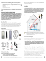
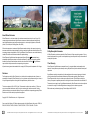
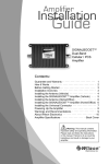
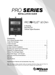
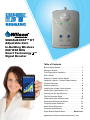
SIGNALBOOST
DT
™
DESKTOP
CELLULAR SIGNAL BOOSTER
SIGNALBOOST™ DT
Adjustable Gain
In-Building Wireless
800/1900 MHz
Smart Technology ™
Signal Booster
Table of Contents
Before Getting Started. . . . . . . . . . . . . . . . . . . . . . . . . 1
Package Contents. . . . . . . . . . . . . . . . . . . . . . . . . . . . 1
Tools Required for Installation. . . . . . . . . . . . . . . . . . . 1
How it Works. . . . . . . . . . . . . . . . . . . . . . . . . . . . . . . . 2
Reasons for Weak Cellular Signals. . . . . . . . . . . . . . . 2
Installation Options - Outside Cradle Antenna. . . . . . 3
Antenna Placement. . . . . . . . . . . . . . . . . . . . . . . . . . . 3
Antenna Separation. . . . . . . . . . . . . . . . . . . . . . . . . . . 4
Installing the Outside Cradle Antenna. . . . . . . . . . . . . 5
Installing the Signal Booster Unit. . . . . . . . . . . . . . . . 8
Powering Up the Signal Booster. . . . . . . . . . . . . . . . . 8
Find the Strongest Signal . . . . . . . . . . . . . . . . . . . . . . 9
Understanding the Indicator Lights. . . . . . . . . . . . . . 10
Warnings and Recommendations. . . . . . . . . . . . . . . 11
Frequently Asked Questions. . . . . . . . . . . . . . . . . . . 11
About Wilson Electronics. . . . . . . . . . . . . . . . . . . . . . 13
Guarantee and Warranty. . . . . . . . . . . . . . . . . . . . . . 14
Signal Booster Specifications . . . . . . . . . . Back Cover
Appearance of device and accessories may vary.
Installation Instructions for the Following Wilson Electronics Signal Booster:
SignalBoost™ DT Adjustable Gain In-Building Wireless 800/1900 MHz Smart Technology ™ Signal Booster
Model # 271265
FCC ID: PWO271265IC: 4726A-271265
The term “IC” before the radio certification number only signifies that Industry Canada technical specifications
were met.
Welcome to the Wilson Electronics Family of Products!
Thank you for purchasing the Wilson Electronics SignalBoost DT system. You are just minutes away from
enjoying improved performance from your cellular phone and/or laptop data card. When installed properly, the
SignalBoost DT will significantly reduce dropped calls and improve both voice and data signal quality. By
taking a few minutes to read and follow the simple instructions in this guide, you will get the most out of your
new SignalBoost DT system. If you have questions during or after installation, please do not hesitate to
contact a member of our Technical Support team by phone 866-294-1660 or 435-673-5021 or email
[email protected]. We are here to help!
Note: Need help installing your SIGNALBOOST™ DT? Check out our latest complete Installation Video at
www.wilsonelectronics.com/dt-install.aspx.
How it Works
Your Wilson Electronics SignalBoost DT works by picking up a cellular signal from the Outside Antenna
facing the cell tower. The Signal Booster then increases the signal and transmits it to the Desktop Antenna.
The Desktop Antenna then transmits the boosted signal to your cell phone or laptop data card. There are
several ways to mount the Outside Antenna, (see Figure 2 on page 3) but for the best results, mount the
Outside Antenna on a pole outside your building facing a cell tower.
Aim toward
cell tower
Figure 1
Note: If minimum
20’ separation is not
possible, see page 5.
Before Getting Started
20
um
This guide will help you properly install a Wilson Electronics SignalBoost DT. It is recommended that
you read through all of the installation steps and familiarize yourself with the product. Read the
instructions and visualize where you want to place the components before mounting any equipment. Please
contact Wilson Electronics Technical Support with any questions at 866-294-1660 or 435-673-5021.
M
Area Needing
Increased
Signal
tal
on
riz
Cell
Tower
n
tio
ara
p
f se
to
fee
ho
m
ini
Minim
Min. 20
Aim toward
cell tower
0 ho
um 2
Desktop
Antenna
n
aratio
f sep
et o
tal fe
rizon
tal ft of
horizon
on
separati
Package Contents:
Accessories packaged may not exactly match the below photos due to different kit options
SIGNALBOOST DT
Outside Antenna
Option C (indoor)
Window Mount
Outside Antenna
Option B (outdoor)
Wall Mount
Outside Antenna
Option A (outdoor)
Pole Mount
Warning: Make sure the position of the Desktop Antenna observes the minimum required separation distance from the outside Cradle Antenna. The Desktop Antenna must be positioned at least 20 vertical feet from the outside Cradle Antenna.
Reasons for Weak Cellular Signals
SignalBoost DT
Coax Cables
Desktop
Antenna
Cradle Antenna
(20 and 30 feet)
(Mount outside on pole, wall, or
inside on a rafter or a window)
Cable
Connector
Appearance
of device and
accessories
may vary.
1. Pole Mount
(Packet A)
2. Wall Mount
(Packet B)
Tools Required for Installation:
3. Window Mount
(Packet C)
AC Power Supply
(Not included with
some models)
Depending on your particular installation, you will need the following tools:
1. Pole mount - 1/4 inch open-end wrench or adjustable wrench
2. Wall mount or Rafter mount - Drill and 3/16 inch bit, Phillips-head screwdriver
1
Contact Wilson Electronics Technical Support Team with any questions at 866-294-1660 or email: [email protected]. Hours: 7 am to 6 pm MST.
Anyone who uses a cell phone or cellular data card knows the frustration of not being able to connect to or
maintain a strong cellular signal. When this occurs, it is generally due to one of two reasons:
1. Location of the Nearest Cell Tower – Cell towers are situated to provide broad coverage; however, there
are many areas in which signal strength may be reduced by topographic features or by local government
restrictions on the height or placement of the towers themselves. Rural areas generally have fewer cell
towers than urban regions.
2. Natural and Man-made Obstructions – Signal strength can also be negatively affected by trees, hills,
buildings and other obstructions. You may be relatively close to a cell tower but still unable to make a call.
This often occurs in homes, offices and other buildings in which stucco, concrete or metal block the signal.
The outside Cradle Antenna receives the outside signal and sends it through the cable to the SignalBoost
DT, where it is amplified and transmitted through the Desktop Antenna into the room. When the Desktop
Antenna picks up a signal from your cell phone or data card, the Signal Booster then amplifies that signal and
transmits it through the cable to the outside Cradle Antenna and back to the cell tower.
(Note: The SignalBoost DT will only operate if there is adequate outside signal to amplify.)
Contact Wilson Electronics Technical Support Team with any questions at 866-294-1660 or email: [email protected]. Hours: 7 am to 6 pm MST.
2
Figure 2
*Note: For Window Installation: Most modern dual-pane windows will not pass cellular signals
because of a metal oxide film applied during manufacturing. We recommend mounting the
antenna outside for the best performance.
Best
Antenna
and
Cradle on a
pole
(facing
Cell cell tower)
Tower
Cell
Tower
Pole Installation (A)
Good
Better
Wall Installation (B)
OK*
Antenna and
Cradle (high on
inside of the
rafter, facing
cell tower)
Antenna and
Cradle (on
outside of
the building
as high as
possible,
facing cell
tower)
Recommended 18 inches minimum
Antenna and
Cradle (high on
the inside of the
window, facing
cell tower)
Rafter Installation (C)
Window Installation (D)*
See Note Above*
The outside Cradle Antenna is directional – it receives and transmits best in one direction. The round Wilson
Electronics insignia indicates the side of the antenna that should face toward the cell tower when the unit is placed in
the cradle. Note: The weaker the signal is at the outside Cradle Antenna, the shorter the distance the Desktop
Antenna will transmit; therefore, signal strength at the outside Cradle Antenna is extremely important. In
some kits the SignalBoost DT comes with all necessary parts for installation of the outside Cradle Antenna in four
alternative locations (see Figure 2 on page 3):
A.
B.
C.
D.
BEST: Outside on a pole. See page 5 for installation instructions.
BETTER: Outside on a wall. See page 6 for installation instructions.
GOOD: In the attic on a rafter. See page 7 for installation instructions.
OK: Inside on a window. See page 7 for installation instructions.
Rule #1 Once you find a good signal location for the Outside Antenna, the front of the Outside Antenna (the Wilson Electronics insignia) must face toward the cell tower, and face AWAY FROM the Desktop
Antenna. The Desktop Antenna must be positioned at least 20 vertical feet from the outside antenna
(see Figure 4).
Rule #2 The Desktop Antenna should be placed 18 inches or more away from the Signal Booster, with the logo
pointed away from the Signal Booster (see figure 4).
Cell
Tower
CORRECT
Cradle
Antenna
Signal Booster
with Desktop
Antenna
Cradle
Antenna
Signal Booster
with Desktop
Antenna
The Wilson Electronics insignia on
the outside Cradle Antenna should
face toward the cell tower and
away from the Desktop Antenna.
Cell
Tower
Cradle
Antenna
Cradle
Antenna
M
riz inim
on
u
tal m
20
fee
Ho
If antennas are too close,
a red light will come on.
t
Signal Booster
with Desktop
Antenna
Signal Booster
with Desktop
Antenna
Even at 20 feet, the Signal Booster may shut down, as indicated by the red light. By moving the Desktop
Antenna further away from the Signal Booster, you may be able to change the red light to a green light,
indicating that the system is operating properly (see Figure 5).
INCORRECT
Cell
Tower
Vertical Separation
Minimum
Vertical
20 feet
Figure 3
3
The location of the Desktop Antenna in relation to the Outside Antenna is very important. Poor antenna
placement increases the possibility of oscillation (feedback), which causes system shutdown (indicated by a
red light on the DT). Observe the following rules for correct antenna placement and optimum DT performance.
Horizontal Separation
The location of the SignalBoost DT with the Desktop Antenna in relation to the outside Cradle Antenna is
very important. Once you find a good signal location for the outside Cradle Antenna, the Signal Booster and
Desktop Antenna need to be located behind it to reduce the possibility of oscillation (feedback) (indicated by
a red indicator light on the Signal Booster). In other words, the front of the outside Cradle Antenna (indicated
by the Wilson Electronics insignia) needs to face in the direction of the cell tower and not in the direction of the
Signal Booster and the Desktop Antenna (see Figure 3).
Position the Desktop Antenna with the logo on the
antenna facing away from both the Signal Booster and
outside Cradle Antenna.
Antenna Separation
Figure 4
Antenna Placement
Cell
Tower
INCORRECT
CORRECT
Installation Options - Outside Cradle Antenna
In addition, it is important that the Desktop Antenna be positioned so that the logo is not pointed towards the
Signal Booster or the outside Cradle Antenna, as shown in Figure 3. The Desktop Antenna is recommended to
be 18 inches or more away from the Signal Booster as shown below.
Never point the outside Cradle Antenna across the
building toward the Desktop Antenna. Do not let the
outside Cradle Antenna and the Desktop Antenna
(logo side) transmit toward each other.
Contact Wilson Electronics Technical Support Team with any questions at 866-294-1660 or email: [email protected]. Hours: 7 am to 6 pm MST.
Figure 5
Min. 18 in.
separation
If you are unable to maintain the 20-foot minimum separation between antennas, it may be possible to achieve
normal operation (a green light) at less than 20 feet by moving the Desktop Antenna to a different position, as
noted above, and rotating the Desktop Antenna in relation to the outside Cradle Antenna (see Figure 6). Do not
position the Desktop Antenna towards the Signal Booster unit or the outside Cradle Antenna.
Contact Wilson Electronics Technical Support Team with any questions at 866-294-1660 or email: [email protected]. Hours: 7 am to 6 pm MST.
4
5. Insert the antenna into the cradle with the Wilson Electronics
insignia facing in the direction of the cell tower. The cable
connection should protrude through the bottom of the cradle.
Figure 6
Figure 8
6. Connect the supplied cable to the antenna. Route the cable as
desired to where the Signal Booster will be located. Depending
on the distance between the Signal Booster and antenna, you
may need one or both lengths of the supplied cable. If you use
both, connect them together with the
supplied cable connector.
If you are not able to change the red light to green in this manner, more separation is needed between the
outside Cradle Antenna and the Desktop Antenna.
Troubleshooting Tip:
If your installation
maintains at least
20 vertical feet of
separation distance but
the red light remains
illuminated, then relocate
the Desktop Antenna
more directly beneath the
position of the Outside
Antenna, inside the
imaginary Null Zone
of Signal (see Figure
7-1 & 7-2). Make sure
the relocated Desktop
Antenna observes rules
1 & 2 on page 4.
BETTER: Outside Wall Mount (Packet B)
1. Select a location on an outside wall as high as possible and at least 20
feet away from where the Signal Booster will be located (see Figure 9).
2. Using the cradle as a template, position it on the wall in the desired
location and mark the screw holes with a pencil.
Cell
Tower
3. Drill two holes where marked, using a 3/16-inch bit and insert the screw
anchors.
4. Line up the holes in the cradle with the screw anchors and mount the
cradle to the wall using two screws and two washers (see Figure 10).
Tighten the screws with a Phillips-head screwdriver.
Null Zone
Null Zone
5. Insert the antenna into the cradle with the Wilson Electronics insignia
facing in the direction of the cell tower. The cable connection should protrude through the bottom of
the cradle.
5 feet
5 feet
Figure 7-1: BEST: Outside Pole Mount Option
BEST: Outside Pole Mount (Packet A)
1. Select a location on the roof where the outside Cradle Antenna
can be mounted on a pole directly above the Desktop Antenna
with at least 15 feet vertical separation. See Figure 7-1.
2. The supplied pole-mount bracket is designed to accommodate
a pole diameter of 1 to 2 inches. Install the pole in the desired
location using your own hardware.
6. Connect the supplied cable to the antenna. Route the cable as desired to where the Signal Booster will be
located. Depending on the distance between the Signal Booster and antenna, you may need one or both
lengths of the supplied cable. If you use both, connect them together with the supplied cable connector.
Figure 7-2: BETTER: Rafter Mounting Option
Installing the Outside Cradle Antenna
Warning: RF Safety: FCC regulations require that any antenna (inside or outside) used with this Signal Booster may not have gain that exceeds 15 dBi. All Wilson Electronics antennas meet this requirement. Inside antennas must have at least 8 inches of separation from all persons. Outside antennas must be farther than 30 inches from all persons.
Antenna
and
Cradle
Cell
Tower
Figure 9
Min. 20 Ho
(see page
rizontal fee
t
4 for vertic
al)
3. Insert the supplied U-bolt through the holes in the cradle and
slide one half of the bracket assembly onto the U-bolt (see
Figure 8).
4. Fitting the assembly onto the pole, slide the second half of the
bracket onto the U-bolt and secure it with lock washers and
nuts. Be sure the cradle is at the desired height on the pole and
is rotated toward the nearest cell tower before tightening the
nuts (do not over-tighten the nuts.)
5
Antenna
and
Cradle
Figure 10
Cable Connector
Cable Connector
Cable
Contact Wilson Electronics Technical Support Team with any questions at 866-294-1660 or email: [email protected]. Hours: 7 am to 6 pm MST.
Cable
Contact Wilson Electronics Technical Support Team with any questions at 866-294-1660 or email: [email protected]. Hours: 7 am to 6 pm MST.
6
GOOD: Rafter Mounting Option
Recommended: Installing the Lightning
Surge Protector (sold separately)
Green cable is the ground wire
(not included)
1. Select a location in the buildings rafters where the outside Cradle
Antenna can be mounted directly above the Desktop Antenna with at
least 20 feet vertical separation (see Figure 7-2 on page 5).
Install the Lightning Surge Protector (LSP)
close to the Signal Booster. Attach the
cable from the Outside Antenna to the surge
protector. Ensure the LSP is properly
grounded. (For RG6 cable use #859988-75
Ohm (shown), for 50 Ohm use #859902). May
be purchased at www.WilsonElectronics.com or
by calling 800-204-4104.
White cable is from
outside antenna
2. Using the cradle as a template, position it on the rafter in the desired
location and mark the screw holes with a pencil.
Lightning Surge Protector
Power Supply cable
3. Drill two holes where marked, using a 3/16-inch bit and insert the
screw anchors.
4. Line up the holes in the cradle with the screw anchors and mount the
cradle to the wall using two screws and two washers (see Figure 10
on page 6). Tighten the screws with a Phillips-head screwdriver.
Wilson® Electronics recommends that all AC power supplies for home electronics
be plugged into a Surge Protector Power Strip.
5. Insert the antenna into the cradle with the Wilson Electronics insignia facing in the direction of the
cell tower. The cable connection should protrude through the bottom of the cradle.
Installing the Signal Booster Unit
6. Connect the supplied cable to the antenna. Route the cable as desired to where the Signal Booster will be
located. Depending on the distance between the Signal Booster and antenna, you may need one or both
lengths of the supplied cable. If you use both, connect them together with the supplied cable connector.
1. Select a location to install the Signal Booster that is away from excessive heat, direct sunlight, moisture
and that has proper ventilation. Do not place the Signal Booster in an air-tight enclosure. Recommended
installation locations for in-building Signal Boosters are: On a shelf or In a closet, and near a power outlet.
OK: Inside Window Mount (Packet C)*
*See Note Below
1. Select a location on the inside of the window as high as possible and at
least 20 feet from where the Signal Booster will be located.
Antenna
and
Cradle
2. Clean the area on the glass with the supplied alcohol prep pad.
3. Mount the outside Cradle Antenna, use the suction cups provided in
Packet C. Using a twisting motion, press the suction cups into the two
holes on the antenna cradle (see Figure 11), then press the cradle onto
the glass at the desired location.
Suction cup
installation
4. Insert the antenna into the cradle with the Wilson Electronics
insignia facing in the direction of the cell tower. The cable
connection should protrude through the bottom of the cradle.
5. Connect the supplied cable to the antenna and route the cable as
desired to where the Signal Booster will be located. Depending on
the distance between the Signal Booster and antenna, you may need one or both lengths of the supplied
Note: It is important to have adequate air ventilation. Maintain at least 6 inches of clearance from
surrounding objects.
2. Place the Signal Booster on a desk, table or similar surface where you have routed the cable.
3. Run the Outside Antenna cable to the Signal Booster and attach it to the connector labeled “Outside
Antenna” on the Signal Booster. Run the Inside Antenna cable to the Signal Booster and attach it to the
connector labeled “Inside Antenna” on the Signal Booster. Note: Be careful when plugging the connector in
to avoid bending the center pins on the connectors.
Powering Up the Signal Booster
1. Ensure that the distance between the Desktop
Antenna and the outside Cradle Antenna is a
minimum of 20 horizontal feet (see Figure 12).
If you are using a different antenna configuration,
see the separation guidelines for your specific
antenna or call Wilson Electronics Technical
Support Team at 866-294-1660 or
435-673-5021.
2. Never point the front of a directional Outside
Antenna toward the Inside Antenna.
* Note: For Window Installation: Modern Dual-Pane windows will not pass cellular signals because of a metal oxide film applied during manufacturing. We recommend mounting the antenna outside for the best performance.
Figure 11
7
Figure 12
Desktop
Antenna
Min.
et
20 fe
SignalBoost DT
3. Ensure that both the Outside Antenna cable and the Inside Antenna cable are connected to the Signal
Booster and the connections are tight before powering up the Signal Booster.
4. Plug the 6-volt power supply into the Signal Booster input marked “POWER” (carefully, to avoid damaging the
center pin) and then into a wall outlet.
5. Make sure the position of the Desktop Antenna observes the minimum required separation distance from
the outside Cradle Antenna. The Desktop Antenna must be positioned at least 20 horizontal/vertical feet
from the outside Cradle Antenna.
6. If the Signal Booster does not have a green light please see page 10 for troubleshooting tips.
Contact Wilson Electronics Technical Support Team with any questions at 866-294-1660 or email: [email protected]. Hours: 7 am to 6 pm MST.
Contact Wilson Electronics Technical Support Team with any questions at 866-294-1660 or email: [email protected]. Hours: 7 am to 6 pm MST.
8
7. If you know that only one frequency band (800 or 1900) is available in your coverage area (or going to be
used), reduce the gain control on the frequency band that is NOT in use to the minimum. This will reduce
the power consumption of the Signal Booster.
8. Using multiple Signal Boosters in one installation may cause interference to the cell tower.
9. If you find you still have a weak signal after powering up the Signal Booster, see signal strength figures
below for additional help. Note: The weaker the signal is at the Cradle Antenna, the shorter the distance
the Desktop Antenna will transmit; therefore, signal strength at the Cradle Antenna is extremely important.
Find the Strongest Signal
Before you install your SignalBoost DT, it is very important that you determine the location of the best
available cellular signal. This will affect where you place the outside Cradle Antenna and will help you get the
best performance from your system. You will find the strongest signal outside your house or building, preferably
at the highest place available. Your cell phone can help you find the strongest outside signal, using any or all
of the following methods:
Understanding the Signal Booster Lights and Trouble Shooting
During installation mode the Signal Booster is resetting itself very quickly to aid the installer. The Signal
Booster is equipped with two indicator lights, one for the 800 MHz band and the other for the 1900 MHz band.
For the first 15 minutes that the booster is plugged in, it is programed for a test and alignment period. During
this time, both lights will do one of the following 4 things: (Note: If after the initial 15 minutes you are not done
with the installation, the Signal Booster can be reset and enter installation mode again by disconnecting and
reconnecting the power supply from the booster.)
BLINKING
GREEN:
If the Signal Booster is blinking green, the Signal Booster is operating properly. If you
are happy with the coverage area in your building, then you are done. Blinking will stop after
the 15 minute installation period.
BLINKING
ORANGE:
The Signal Booster is experiencing receiver overload. The Signal Booster has protection
shutoff circuits to prevent the disruption of cell towers. If one or both lights are blinking
orange, this indicates that the Signal Booster has shut down due to close proximity to a cell
tower. First, turn down the gain control on the band that is blinking until you get a
blinking green light. The Signal Booster is now working with reduced gain. If the gain
is not adequate for good coverage, you will need to turn the gain to maximum and then
turn the Outside Antenna away from the cell tower until the light turns to blinking
green. If the Signal Booster will not respond, turn the gain down 5 dB and move the Outside
Antenna. Continue to adjust the gain and the antenna position until the light turns blinking
green. Contact Wilson Electronics Technical Support Team for assistance: 866-294-1660.
1. Place calls from several locations outside your building and note where you get the best reception.
2. Check the bar indicator on your cell phone display and note where the signal appears to be the strongest.
Note: Cell phone bars are only an approximation of signal strength and vary from phone to phone. They
can take up to 30 seconds to reset to a new reading. Be patient and repeat your signal check several times.
3. The best way of getting the strongest signal is to have one person on the roof to rotate the Outside Antenna,
which is connected to the Signal Booster, while the second person is watching the signal strength on the
phone inside the building. This allows you to read the signal strength from the cell tower. Turn the Outside
Antenna 45 degrees at a time. It is preferable to have the phone in the test mode so the numerical signal
strength can be read since bars are not the most accurate. Go to the website www.WilsonElectronics.com for
help in finding the test mode for your phone. Always make sure the person inside the building gives the phone
time to register (between 10-30 seconds for phone to reset to the new signal reading). Signal readings usually
appear as a negative number (for example, -86). The closer you get to zero the stronger the signal (see
Signal Strength Figure). Once you have determined where the outside signal is strongest, you should plan to
install the outside Cradle Antenna in that general area, with the antenna facing towards the cell tower (see the
following section for alternative installation options).
SOLID
RED:
Cell Signal
Cradle
Antenna
Cell Tower
If either of the two lights on the Signal Booster are solid red, this indicates that the Signal
Booster has shut down on that frequency to prevent an oscillation (feedback). First, make
sure that all the connections are tight. Then reduce the gain of the Signal Booster in
small increments by rotating the gain control, counter-clockwise, wait 5 seconds
between each adjustment for the Signal Booster to reset, continue this adjustment
until the light turns blinking/solid green. When you are turning down the gain, you are
reducing the inside coverage area. If the amount of coverage area is sufficient for your
needs and the light is green the installation is complete. If the coverage area is not
large enough, it is necessary to increase the separation distance of the antennas
by moving them horizontally or vertically farther apart, or both. Then increase the
gain until the red light comes on, and then slightly keep decreasing the gain until the
green or blinking green light appears. If after separating the antennas your coverage
area is still too small, contact Wilson Electronics Technical Support Team for assistance:
866-294-1660.
If your installation takes longer than 15 minutes, it is possible to re-enter the installation
mode by disconnecting and reconnecting the power supply from the Signal Booster.
SOLID
GREEN:
Signal Strength Figure
EXCELLENT
9
-50dB
-60dB
GOOD
-70dB
-80dB
POOR
-90dB
-100dB
NO
SIGNAL
The indicator lights on the Signal Booster will be a solid green after the first 15 minute
installation period and the unit is powered up and working properly.
Note: Oscillation (feedback) can occur when the Outside Antenna is too close to the antenna inside the house. An oscillation in a
Signal Booster is similar to when a microphone is too close to a speaker in a sound system, resulting in a loud whistle. An oscillation
in the Signal Booster, if allowed to occur, can affect nearby cell towers ability to handle calls.
-110dB
Contact Wilson Electronics Technical Support Team with any questions at 866-294-1660 or email: [email protected]. Hours: 7 am to 6 pm MST.
Contact Wilson Electronics Technical Support Team with any questions at 866-294-1660 or email: [email protected]. Hours: 7 am to 6 pm MST.
10
Warnings and Recommendations
Warning: Warning:
RF Safety: FCC regulations require that any fixed outside antenna used with this Signal
Booster may not have gain (less cable loss) that exceeds 15 dBi and must be located at
least 30 inches from all people. Inside antennas must not exceed 7 dBi gain (less cable
loss) in the 800 MHz band or 10 dBi gain (less cable loss) in the 1900 MHz band and must
be located at least 8 inches from all people.
If the cable is shortened, or if a different type of cable is used, or if a different antenna is
used, consult with Wilson Electronics Technical Support to verify that the planned installation
is safe. Call 866-294-1660 or 435-673-5021, or email [email protected].
Can I use my own cable for my installation?
Yes! However, the commonly available low-loss RG6 cable included with your product has been specifically
selected for the SignalBoost DT. RG6 is a commonly available cable, you can buy it from Wilson
Electronics, or from your local electronics/hardware store. Use of another type or longer length of cable will
likely degrade the system’s performance.
There are frequently several people using cell phones in my office at the same time – will the SignalBoost
DT improve the signal for all of them?
Absolutely! The SignalBoost DT is designed to support multiple users simultaneously (within the range of
the Desktop Antenna).
Can I use different antennas than the ones supplied in the box?
Yes! While the SignalBoost DT is designed to give you reliable signal improvement with the included
antennas, Wilson Electronics offers a variety of optional antennas and accessories that enable you to
customize your SignalBoost DT to your specific needs. Visit www.WilsonElectronics.com for details.
Warning: Connecting the Signal Booster directly to the cell phone with use of an adapter will damage
the cell phone.
Warning: Attach the Desktop Antenna and connect the outside Cradle Antenna before powering up
the Signal Booster.
Warning: Use only the power supply provided in this package. Use of a non-Wilson Electronics
product may damage your equipment.
Warning: Always operate cell phone at least three feet from the Desktop Antenna.
For Weak Areas with Insufficient Signal
Warning: The Signal Booster unit is designed for use in an indoor, temperature-controlled environment
(less than 100 degrees Fahrenheit). It is not intended for use in attics or similar locations
subject to temperatures in excess of that range.
Warning:
Take care to ensure that neither you nor the pole comes near any power lines during
installation.
In areas with particularly weak outside signals, additional coverage can be obtained by upgrading the Inside
Antenna and replacing it with a high-gain inside Panel Antenna (Wilson part #301147). This antenna (which
includes RG58 cable) can double the inside coverage area (See Figure 13). Additional coverage can be
obtained by upgrading to the Outside Antenna option to #301157 Outdoor Panel or #304475 Wide Band
Directional Antenna. To purchase call 800-204-4104 or www.WilsonElectronics.com.
Warning:
The directional antenna must always be located so the back or side points to the Inside
Antenna. Never point the front of the Outside Antenna toward the Inside Antenna — this is to
prevent oscillation.
I have questions about my installation – where can I get some help?
Wilson Electronics Technical Support representatives are just a phone call or email away.
Call 866-294-1660 or 435-673-5021, or send an email to [email protected].
Figure 13
Recommendation: Lightning surge protection is recommended for all in-building installations.
Frequently Asked Questions
What kind of improvement in cell phone performance can I expect with the SignalBoost DT?
The SignalBoost DT’s performance will depend somewhat on the strength of the cellular signal outside
your home or building. Regardless, if you install the SignalBoost DT in accordance with the instructions in
this guide, you can expect a significant improvement in your ability to use your cell phone or cellular data card
indoors.
Cell
Tower
Minimum 20
feet vertical
separation
Where should I install my SignalBoost DT and Desktop Antenna to get the best coverage?
You should install the Signal Booster and Desktop Antenna in the area where you most need an improved
signal. The farther you are from the Inside Antenna, the less improvement you will experience. It is also
important to install the outside Cradle Antenna in a location where you have the strongest outside signal (see
page 3). Also keep in mind the distance between the Signal Booster and the outside Cradle Antenna. You will
need at least 20 feet of separation to prevent the start of oscillation (feedback), but you will probably want to
stay within the 50-foot length of the cable. (Additional cable and the necessary connectors are available from
your Wilson Electronics dealer, but using more cable will result in some signal loss.)
I have a Nextel phone – will the SignalBoost DT boost that signal?
The SIGNALBOOST DT is not designed for iDEN/Nextel frequency, however, Wilson Electronics offers
specific Signal Boosters for iDEN/Nextel users. Visit www.WilsonElectronics.com for details.
11
Contact Wilson Electronics Technical Support Team with any questions at 866-294-1660 or email: [email protected]. Hours: 7 am to 6 pm MST.
Cradle
Antenna
Panel
Antenna
Optional Panel Antenna
(with cable) for improved coverage
inside the building
(Wilson part # 301147)
Signal
Booster
Contact Wilson Electronics Technical Support Team with any questions at 866-294-1660 or email: [email protected]. Hours: 7 am to 6 pm MST.
12
About Wilson Electronics
Wilson Electronics, Inc. has been a leader in the wireless communications industry for over 40 years. The
company designs and manufactures Signal Boosters, antennas and related components that significantly
improve cellular telephone signal reception and transmission in a wide variety of applications, both mobile
(marine, RV, vehicles) and in-building (home, office, M2M).
With extensive experience in antenna and Signal Booster research and design, the company’s engineering
team uses a state-of-the-art testing laboratory, including an anechoic chamber and network analyzers, to finetune antenna designs and performance. For its Signal Boosters, Wilson Electronics uses a double electrically
insulated RF enclosure and cell tower simulators for compliance testing.
Wilson Electronics Signal Boosters feature patent-pending Smart Technology ™ that enables them to
automatically adjust their power based on cell tower requirements. By detecting and preventing oscillation
feedback, signal overload and interference with other users, these Smart Technology ™ Signal Boosters
improve network cell phone areas without compromising carrier systems.
All products are engineered and assembled in the company’s 55,000-square-foot headquarters in St. George,
Disclaimer
The information provided by Wilson Electronics, Inc. is believed to be complete and accurate. However, no
responsibility is assumed by Wilson Electronics, Inc. for any business or personal losses arising from its use, or
for any infringements of patents or other rights of third parties that may result from its use.
This device complies with Part 15 of FCC rules. The transaction is subject to two conditions: (1) This device
may not cause harmful interference, and (2) this device must accept any interference received, including
interference that may cause undesired operation. Changes or modifications not expressly approved by Wilson
Electronics could void the authority to operate this equipment.
30-Day Money-Back Guarantee
All Wilson Electronics products are protected by Wilson Electronics 30-day money-back guarantee. If for any
reason the performance of any product is not acceptable, simply return the product directly to the reseller with
a dated proof of purchase.
1-Year Warranty
Wilson Electronics Signal Boosters are warranted for one (1) year against defects in workmanship and/or
materials. Warranty cases may be resolved by returning the product directly to the reseller with a dated proof
of purchase.
Signal Boosters may also be returned directly to the manufacturer at the consumer’s expense, with a dated
proof of purchase and a Returned Material Authorization (RMA) number supplied by Wilson Electronics.
Wilson Electronics shall, at its option, either repair or replace the product. Wilson Electronics will pay for
delivery of the repaired or replaced product back to the original consumer if located within the continental U.S.
This warranty does not apply to any Signal Boosters determined by Wilson Electronics to have been subjected
to misuse, abuse, neglect, or mishandling that alters or damages physical or electronic properties.
RMA numbers may be obtained by phoning Technical Support at 866-294-1660.
Copyright © 2011 Wilson Electronics, Inc. All rights reserved.
One or more of the following U.S. Patent numbers may apply to the Signal Booster in this product – D596,614;
D596,615; D563,381;7,729,669; 7,486,929; 7,729,656; 7,409,186; 7,783,318; 7,684,838; 12,714,994.
13
Contact Wilson Electronics Technical Support Team with any questions at 866-294-1660 or email: [email protected]. Hours: 7 am to 6 pm MST.
Contact Wilson Electronics Technical Support Team with any questions at 866-294-1660 or email: [email protected]. Hours: 7 am to 6 pm MST.
14
Signal Booster Specifications
SIGNALBOOST™ DT Specifications
Model Number
271265
Outside antenna connectors
F-Female / SMA-Female
Outside antenna impedance
75 / 50 Ohms
Inside antenna connectors
SMA
Inside antenna impedance
50 Ohms
Dimensions
6.5 x 4.5 x 1.75 inch (16.5 x 11.4 x 4.4 cm)
Weight
0.47 lbs (0.213 kg)
Frequency
1
824-894 MHz / 1850-1990 MHz
Passband Gain (nominal)
800 MHz
55 dB
1900 MHz
2
Downlink
800 MHz
45 MHz
1900 MHz
88 MHz
Power output
3
800 MHz
1900 MHz
Power output for single cell phone (uplink)
30.8 dBm
30.5 dBm
Power output for single received channel (downlink)
26.0 dBm
25.2 dBm
Power output for multiple transmitted channels (uplink)
The maximum power is reduced
by the number of channels:
4
60 dB
20 dB Bandwidth (nominal)
Maximum Power
Number of channels
800 MHz
1900 MHz
2
24 dBm
21.3 dBm
3
20.5 dBm
17.8 dBm
4
18.0 dBm
15.3 dBm
5
16.1 dBm
13.3 dBm
6
14.5 dBm
11.8 dBm
Power output for multiple received channels (downlink)
The maximum power is reduced
by the number of channels:
Noise Figure (typical)
Isolation (uplink/downlink)
Power Requirements
Maximum Power
Number of channels
800 MHz
1900 MHz
2
24.8 dBm
23.7 dBm
3
21.3 dBm
20.2 dBm
4
18.8 dBm
17.7 dBm
5
16.8 dBm
15.7 dBm
6
15.3 dBm
14.2 dBm
3.5 dB nominal / 6 dB nominal
> 90 dB
110-240 V AC, 50-60 Hz, 8 W
Notes:
1. Nominal gain is the maximum gain at any frequency in the passband.
2. Nominal bandwidth is the difference between two frequencies that are adjacent to the passband where the amplification is 20 dB lower than the passband
amplification. One of the frequencies is lower than the passband and the other is higher.
3. The Manufacturer’s rated output power of this equipment is for single carrier operation. For situations when multiple carrier signals are present, the rating
would have to be reduced by 3.5 dB, especially where the output signal is re-radiated and can cause interference to adjacent band users. This power
reduction is to be by means of input power or gain reduction and not by an attenuator at the output of the device.
4. The maximum power for 2 or more simultaneous signals will be reduced by 6 dB every time the number of signals is doubled.
3301 East Deseret Drive, St. George, UT 84790
For additional Technical Support visit www.WilsonElectronics.com
or email at: [email protected]
Phone: 866-294-1660 Local: 435-673-5021 Fax: 435-656-2432
www.twitter.com/WilsonCellular
www.facebook.com/WilsonCellular
AIG_110985S_DT_Rev01_11.01.11