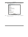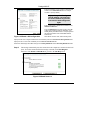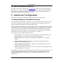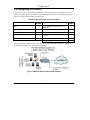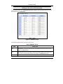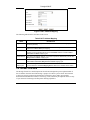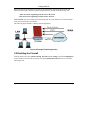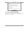
1
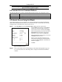
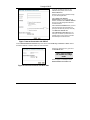
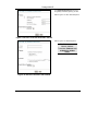
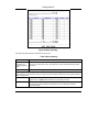
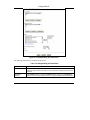
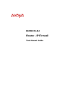
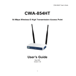
Prestige 650H-E Series
ADSL Router
Compact Guide
Version 3.40
August 2003
Prestige 650H-E
Table of Contents
1 Introducing the Prestige ................................................................................................................ 3
2 Hardware ........................................................................................................................................ 4
2.1 Rear Panel Connections............................................................................................................ 4
2.2 The Front Panel LEDs .............................................................................................................. 5
3 Setting Up Your Computer’s IP Address..................................................................................... 6
3.1 Windows 2000/NT/XP ............................................................................................................... 6
3.2 Checking/Updating Your Computer’s IP Address .................................................................... 7
3.3 Testing the Connection to the Prestige ..................................................................................... 7
4 Configuring Your Prestige ............................................................................................................ 8
4.1 Accessing Your Prestige Via Web Configurator ....................................................................... 8
4.2 Common Screen Command Buttons........................................................................................ 10
4.3 Internet Access Using the Wizard ........................................................................................... 10
4.4 Test Your Internet Connection ................................................................................................ 15
5 Advanced Configuration ............................................................................................................. 15
5.1 Network Address Translation Overview.................................................................................. 15
5.2 Configuring SUA Server ......................................................................................................... 16
5.3 Configuring Address Mapping ................................................................................................ 18
5.4 Firewall Overview................................................................................................................... 19
5.5 Enabling the Firewall ............................................................................................................. 20
5.6 Procedure for Configuring Firewall Rules ............................................................................. 21
5.7 Configuring Source and Destination Addresses ..................................................................... 25
5.8 UPnP Overview....................................................................................................................... 26
5.9 Configuring UPnP .................................................................................................................. 26
6 Troubleshooting ........................................................................................................................... 28
2
Prestige 650H-E
1 Introducing the Prestige
The Prestige 650H-E ADSL router is the ideal all-in-one device for small networks connecting to
the Internet via ADSL. Key features of the Prestige include NAT, Firewall and UPnP. See your
User’s Guide for more details on all Prestige features.
You should have an Internet account already set up and have been given most of the following
information.
INTERNET ACCOUNT INFORMATION
Your device’s WAN IP Address (if given): __________________
DNS Server IP Address (if given): Primary __________________, Secondary _________________
Virtual Path Identifier (VPI): ____________
Virtual Channel Identifier (VCI): ____________
Multiplexing (VC-based or LLC-based):
VC
LLC
Encapsulation:
RFC 1483
ENET ENCAP
Ethernet Encapsulation Gateway IP Address: ____________________
PPPoA
User Name: ____________
PPPoE
Service Name: ____________
Password: ____________
User Name: ____________
Password: ____________
3
Prestige 650H-E
2 Hardware
2.1 Rear Panel Connections
Figure 1 Prestige Hardware Connections
Table 1 Prestige Rear Panel Description
LABEL
DESCRIPTION
1.
DSL
Connect to a telephone jack using the included phone wire.
2.
LAN 1..4
Connect to a computer/external hub using an Ethernet cable.
3.
POWER
Connect to a power source using the power adapter for your region (see your User’s Guide).
After you’ve made the connections, connect the power cable to a power supply and push in the power button to
turn on the Prestige.
The PWR LED turns on. The SYS LED blinks while performing system testing and then turns steady on if the
testing is successful. A LAN LED turns on if a LAN port is properly connected.
RESET
You only need to use this button if you’ve forgotten the Prestige’s password. It returns the
Prestige to the factory defaults (password is 1234, LAN IP address 192.168.1.1 etc.; see your
User’s Guide for details).
4
Prestige 650H-E
2.2 The Front Panel LEDs
Figure 2 Prestige Front Panel
Refer to the following table for more detailed LED descriptions.
Table 2 Front Panel LED Description
LED
PWR/SYS
DSL
PPP/ACT
LAN 1-4
COLOR
Green
STATUS
DESCRIPTION
On
The Prestige is receiving power and functioning properly.
Blinking
The Prestige is rebooting.
Off
The system is not ready or has malfunctioned.
Red
On
Power to the Prestige is too low.
Green
On
The Prestige is linked successfully to a DSLAM.
Blinking
The Prestige is initializing the DSL line.
Off
The DSL link is down.
Blinking
The Prestige is sending/receiving data.
Off
The system is ready, but is not sending/receiving data.
Amber
On
The connection to the PPPoE server is up.
Green
On
The Prestige has a successful 10Mb Ethernet connection.
Blinking
The Prestige is sending/receiving data.
Off
The Prestige does not have 10Mb Ethernet connection.
On
The Prestige has a successful 100Mb Ethernet connection.
Blinking
The Prestige is sending/receiving data.
Off
The Prestige does not have 100Mb Ethernet connection.
Green
Amber
5
Prestige 650H-E
3 Setting Up Your Computer’s IP
Address
Skip this section if your computer is already set up to accept a dynamic IP
address. This is the default for most new computers.
The Prestige is already set up to assign your computer an IP address. Use this section to set up your
computer to receive an IP address or assign it a static IP address in the 192.168.1.2 to 192.168.1.254
range with a subnet mask of 255.255.255.0. This is necessary to ensure that your computer can
communicate with your Prestige.
Your computer must have an Ethernet card and TCP/IP installed. TCP/IP should already be installed
on computers using Windows NT/2000/XP, Macintosh OS 7 and later operating systems.
3.1 Windows 2000/NT/XP
1.
In Windows XP, click start, Control Panel. In Windows 2000/NT, click Start, Settings, Control Panel.
2.
In Windows XP, click Network Connections.
In Windows 2000/NT, click Network and Dial-up Connections.
3.
Right-click Local Area Connection and then click Properties.
4.
Select Internet Protocol (TCP/IP) (under the General tab in Win XP) and click Properties.
5.
The Internet Protocol TCP/IP Properties screen opens (the
General tab in Windows XP).
- To have your computer assigned a dynamic IP address, click
Obtain an IP address automatically.
If you know your DNS sever IP address(es), type them in the
Preferred DNS server and/or Alternate DNS server fields.
-To configure a static IP address, click Use the following IP
Address and fill in the IP address (choose one
from192.168.1.2 to 192.168.1.254), Subnet mask
(255.255.255.0), and Default gateway (192.168.1.1) fields.
Then enter your DNS server IP address(es) in the Preferred
DNS server and/or Alternate DNS server fields.
If you have more than two DNS servers, click Advanced, the
DNS tab and then configure them using Add.
6
Prestige 650H-E
6.
Click Advanced. Remove any previously installed gateways in
the IP Settings tab and click OK to go back to the Internet
Protocol TCP/IP Properties screen.
7.
Click OK to close the Internet Protocol (TCP/IP) Properties
window.
8.
Click OK to close the Local Area Connection Properties
window.
3.2 Checking/Updating Your Computer’s IP Address
1.
In the computer, click Start, (All) Programs, Accessories and then Command Prompt.
2.
In the Command Prompt window, type "ipconfig" and then press ENTER to verify that your computer’s IP
address is in the correct range (192.168.1.2 to 192.168.1.254) with subnet mask 255.255.255.0. This is
necessary in order to communicate with the Prestige.
Refer to your User’s Guide for detailed IP address configuration for other Windows and Macintosh
computer operating systems.
3.3 Testing the Connection to the Prestige
1.
Click Start, (All) Programs, Accessories and then Command Prompt.
2.
In the Command Prompt window, type "ping” followed by a space and the IP address of the Prestige
(192.168.1.1 is the default).
7
Prestige 650H-E
3.
Press ENTER and the following screen displays.
C:\>ping 192.168.1.1
Pinging 192.168.1.1 with 32 bytes of data:
Reply
Reply
Reply
Reply
from
from
from
from
192.168.1.1:
192.168.1.1:
192.168.1.1:
192.168.1.1:
bytes=32
bytes=32
bytes=32
bytes=32
time=10ms
time<10ms
time<10ms
time<10ms
TTL=254
TTL=254
TTL=254
TTL=254
Ping statistics for 192.168.1.1:
Packets: Sent = 4, Received = 4, Lost = 0 (0% loss),
Approximate round trip times in milli-seconds:
Minimum = 0ms, Maximum = 10ms, Average = 2ms
Your computer can now communicate with the Prestige using the LAN port.
4 Configuring Your Prestige
This Compact Guide shows you how to use the web configurator only. See
your User’s Guide for background information on all Prestige features and
SMT (System Management Terminal) configuration.
4.1 Accessing Your Prestige Via Web Configurator
Step 1.
Launch your web browser. Enter “192.168.1.1” as the web site address.
Web site address.
Figure 3 Entering Prestige LAN IP Address in Internet Explorer
Step 2.
An Enter Network Password window displays. Enter the user name (“admin” is the
default), password (“1234” is the default) and click OK.
8
Prestige 650H-E
Default user name.
Figure 4 Web Configurator: Password Screen
Step 3.
You should now see the web configurator Site Map screen.
Click Wizard Setup to begin a series of screens to configure your Prestige for the first
time.
Click a link under Advanced Setup to configure advanced Prestige features.
Click a link under Maintenance to see Prestige performance statistics, upload firmware
and back up, restore or upload a configuration file.
Click Logout in the navigation panel when you have finished a Prestige management
session.
WIZARD
Navigation panel
LOGOUT
Figure 5 Web Configurator: Site Map Screen
9
Prestige 650H-E
The Prestige automatically logs you out if it is left idle for five minutes;
press ENTER to log back in again.
4.2 Common Screen Command Buttons
The following table shows common command buttons found on many web configurator screens.
Back
Click Back to return to the previous screen.
Apply
Click Apply to save your changes back to the Prestige.
Reset/Cancel
Click Reset or Cancel to begin configuring this screen afresh.
4.3 Internet Access Using the Wizard
Use the Wizard Setup screens to configure your system for Internet access settings and fill in the
fields with the information in the Internet Account Information table. Your ISP may have already
configured some of the fields in the wizard screens for you.
Step 1.
In the Site Map screen click Wizard Setup to display the first wizard screen.
From the Mode drop-down list box, select Routing
(default) if your ISP allows multiple computers to
share an Internet account. Otherwise select Bridge.
Select the encapsulation type your ISP uses from the
Encapsulation drop-down list box. Choices vary
depending on what you select in the Mode field.
Select the multiplexing method used by your ISP from
the Multiplex drop-down list box.
Enter the correct Virtual Path Identifier (VPI) and
Virtual Channel Identifier (VCI) numbers supplied by
your ISP in the VPI and VCI fields. These fields may
already be configured.
Click Next.
Figure 6 Wizard Screen 1
Step 2.
The second wizard screen varies depending on what mode and encapsulation type you
use. All screens shown are with routing mode. Configure the fields and click Next to
continue.
10
Prestige 650H-E
If your ISP provides the name of your
PPPoE service provider, enter it in the
Service Name field.
Enter the user name and password exactly
as your ISP assigned them.
Select Obtain an IP Address
Automatically if you have a dynamic IP
address; otherwise select Static IP Address
and type your ISP assigned IP address in
the text box below.
Select Connect on Demand when you don't
want the connection up all the time and
specify an idle time-out period (in seconds)
in the Max. Idle Timeout field.
Select Nailed-Up Connection when you
want your connection up all the time. The
Prestige will try to bring up the connection
automatically if it is disconnected.
Figure 7 Internet Connection with PPPoE
From the Network Address Translation drop-down list box, select SUA Only, Full Feature or None. Refer to
the Network Address Translation section for more information.
Enter the IP address given by your ISP in
the IP Address field.
The IP Address field is
not available for bridge
mode.
Refer to Figure 7 for description of the
Network Address Translation field.
Figure 8 Internet Connection with RFC 1483
11
Prestige 650H-E
In the ENET ENCAP Gateway field, enter
the gateway IP address given by your ISP.
Refer to Figure 7 for other field descriptions.
Figure 9 Internet Connection with ENET ENCAP
Refer to Figure 7 for field descriptions.
The IP Address and
Network Address
Translation fields are not
available for bridge
mode.
Figure 10 Internet Connection with PPPoA
12
Prestige 650H-E
Step 3.
Verify the settings in the screen shown next. To change the LAN information on the
Prestige, click Change LAN Configurations. Otherwise click Save Settings to save the
configuration and skip to step 5.
Figure 11 Wizard Screen 3
Step 1.
If you want to change your Prestige LAN settings, click Change LAN Configuration to
display the screen as shown next.
13
Prestige 650H-E
Enter the IP address of your Prestige in dotted decimal
notation in the LAN IP Address field. For example,
192.168.1.1 (factory default).
If you change the Prestige’s
LAN IP address, you must use
the new IP address if you want
to access the web configurator
again.
Enter a subnet mask in dotted decimal notation in the
LAN Subnet Mask field.
Figure 12 Wizard: LAN Configuration
From the DHCP Server drop-down list box, select On
to allow your Prestige to assign IP addresses, an IP
default gateway and DNS servers to computer systems
that support the DHCP client. Select Off to disable
DHCP server.
When DHCP server is used, set the following items:
Specify the first of the contiguous addresses in the IP address pool in the Client IP Pool Starting Address field.
Specify the size or count of the IP address pool in the Size of Client IP Pool field.
Enter the IP address(es) of the DNS server(s) in the Primary DNS Server and/or Secondary DNS Server fields.
Step 2.
The Prestige automatically tests the connection to the computer(s) connected to the LAN
ports. To test the connection from the Prestige to the ISP, click Start Diagnose.
Otherwise click Return to Main Menu to go back to the Site Map screen.
Figure 13 Wizard Screen 4
14
Prestige 650H-E
4.4 Test Your Internet Connection
Launch your web browser and navigate to www.zyxel.com. Internet access is just the beginning.
Refer to the User’s Guide for more detailed information on the complete range of Prestige features.
If you cannot access the Internet, open the web configurator again to confirm that the Internet
settings you configured in the Wizard Setup are correct.
5 Advanced Configuration
This section shows how to configure some of the advanced features of the Prestige.
5.1 Network Address Translation Overview
NAT (Network Address Translation - NAT, RFC 1631) is the translation of the IP address of a host
in a packet. For example, the source address of an outgoing packet, used within one network is
changed to a different IP address known within another network.
In the simplest form, NAT changes the source IP address in a packet received from a subscriber (the
inside local address) to another (the inside global address) before forwarding the packet to the WAN
side. When the response comes back, NAT translates the destination address (the inside global
address) back to the inside local address before forwarding it to the original inside host. Note that
the IP address (either local or global) of an outside host is never changed.
NAT supports five types of IP/port mapping. They are:
1.
One-to-One: One-to-one mode maps one local IP address to one global IP address. Note
that port numbers do not change for One-to-one NAT mapping type.
2.
Many-to-One: Many-to-One mode maps multiple local IP addresses to one global IP
address.
3.
Many-to-Many Overload: Many-to-Many Overload mode maps multiple local IP
addresses to shared global IP addresses.
4.
Many-to-Many No Overload: Many-to-Many No Overload mode maps each local IP
address to unique global IP addresses.
5.
Server: This type allows you to specify inside servers of different services behind the NAT
to be accessible to the outside world.
SUA (Single User Account) is a ZyNOS implementation of a subset of NAT that supports two types
of mapping, Many-to-One and Server. The Prestige also supports Full Feature NAT to map
multiple global IP addresses to multiple private LAN IP addresses of clients or servers using
mapping types.
15
Prestige 650H-E
5.2 Configuring SUA Server
An SUA server set is a list of inside (behind NAT on the LAN) servers, for example, web or FTP,
that you can make visible to the outside world even though SUA makes your whole inside network
appear as a single computer to the outside world.
Table 3 Common Services and Port Numbers
SERVICES
PORT
NUMBER
SERVICES
PORT
NUMBER
ECHO
7
HTTP (Hyper Text Transfer protocol or
WWW, Web)
80
FTP (File Transfer Protocol)
21
POP3 (Post Office Protocol)
110
SMTP (Simple Mail Transfer Protocol)
25
NNTP (Network News Transport Protocol)
119
DNS (Domain Name System)
53
SNMP (Simple Network Management
Protocol)
161
Finger
79
SNMP trap
162
PPTP (Point-to-Point Tunneling Protocol)
1723
Let's say you want to assign ports 22-25 to one server, port 80 to another and assign a default server
IP address of 192.168.1.35 as shown in the next figure.
Figure 14 Multiple Servers Behind NAT Example
16
Prestige 650H-E
If you do not assign an IP Address, then all packets received for ports not
specified in this screen will be discarded.
From the main screen click Advanced Setup and then NAT to open the main NAT screen. Select
SUA Only and click Edit Details.
Figure 15 SUA/NAT Server
The following table describes the labels in this screen.
Table 4 SUA/NAT Server
LABEL
DESCRIPTION
Start Port
No.
Type a port number in this field. To forward only one port, type the port number again in the
End Port field. To forward a series of ports, type the start port number here and the end port
number in the End Port field.
End Port
No.
Type a port number in this field. To forward only one port, type the port number in the Start
Port field above and then type it again in this field. To forward a series of ports, type the last
port number in a series that begins with the port number in the Start Port field above.
IP Address
Enter the inside IP address of the server here.
17
Prestige 650H-E
5.3 Configuring Address Mapping
Some applications do not support NAT mapping using TCP or UDP port address translation. In this
case it is better to use Many-To-Many No Overload mapping as port numbers do not change for
Many-To-Many No Overload (and One-to-One) NAT mapping types. The following figure
illustrates this.
Figure 16 NAT Example
Applications such as some gaming programs are NAT unfriendly because
they embed addressing information in the data stream. These applications
won’t work through NAT even when using One-to-One and Many-To-Many No
Overload mapping types.
Ordering your rules is important because the Prestige applies the rules in the order that you specify.
To change your Prestige’s address mapping settings, click Advanced Setup and NAT. Select Full
Feature and click Edit Details. Click on a rule to display the configuration screen as shown.
18
Prestige 650H-E
Figure 17 NAT: Address Mapping
The following table describes the labels in this screen.
Table 5 NAT: Address Mapping
LABEL
DESCRIPTION
Type
Choose the port mapping type from the drop-down list box. Refer to the mapping types as
discussed previously.
Local Start IP
This refers to the Inside Local Address (ILA), that is the starting local IP address. Local IP
addresses are N/A for Server port mapping.
Local End IP
This is the end local IP address. If the rule is for all local IP addresses, then this field
displays 0.0.0.0 and 255.255.255.255 as the Local End IP address. This field is N/A for
One-to-One and Server mapping types.
Global Start IP
This refers to the global IP address. 0.0.0.0 is for a dynamic IP address from your ISP with
Many-to-One and Server mapping types.
Global End IP
This is the ending Inside Global Address (IGA), that is the starting global IP address. This
field is N/A for One-to-One, Many-to-One and Server mapping types.
Server
Mapping Set
Click this link to go to the NAT - Edit SUA/NAT Server Set screen to edit a server set that
you have selected in the Server Mapping Set field. Refer to the SUA/NAT Server section.
5.4 Firewall Overview
The Prestige firewall is a stateful inspection firewall and is designed to protect against Denial of
Service attacks when activated. The Prestige’s purpose is to allow a private Local Area Network
(LAN) to be securely connected to the Internet. The Prestige can be used to prevent theft,
destruction and modification of data, as well as log events, which may be important to the security
of your network. The Prestige also has packet-filtering capabilities.
19
Prestige 650H-E
When activated, the firewall allows all traffic to the Internet that originates from the LAN, and
blocks all traffic to the LAN that originates from the Internet. In other words the Prestige will:
Allow all sessions originating from the LAN to the WAN
Deny all sessions originating from the WAN to the LAN
LAN-to-WAN rules are local network to Internet firewall rules. The default is to forward all traffic
from your local network to the Internet.
The following figure illustrates a Prestige firewall application.
Figure 18 Prestige Firewall Application
5.5 Enabling the Firewall
From the main screen, click Advanced Setup, Firewall and then Config to open the Configuration
screen. Enable (or activate) the firewall by selecting the Enable Firewall check box as seen in the
following screen.
20
Prestige 650H-E
Figure 19 Enabling the Firewall
5.6 Procedure for Configuring Firewall Rules
From the main screen, click Advanced Setup, Firewall and then Rule Summary (for either local
network to Internet rules or Internet to local network rules) to open the Summary screen. The
following table describes the fields in this screen.
21
Prestige 650H-E
Figure 20 Rule Summary
The following table describes the labels in this screen.
Table 6 Rule Summary
LABEL
DESCRIPTION
The default action
for packets not
matching following
rules
Should packets that do not match the following rules be blocked or forwarded? Make your
choice from the drop down list box. Note that “block” means the firewall silently discards
the packet.
Default Permit Log
Click this check box to log all matched rules in the ACL default set.
The following read-only fields summarize the rules you have created that apply to traffic traveling in the selected
packet direction. The firewall rules that you configure (summarized below) take priority over the general firewall
action settings above.
No.
This is your firewall rule number. The ordering of your rules is important as rules are
applied in turn. The Move field below allows you to reorder your rules.
Source IP
This drop-down list box displays the source addresses or ranges of addresses to which
this firewall rule applies. Please note that a blank source or destination address is
equivalent to Any.
22
Prestige 650H-E
Table 6 Rule Summary
LABEL
DESCRIPTION
Destination IP
This drop-down list box displays the destination addresses or ranges of addresses to
which this firewall rule applies. Please note that a blank source or destination address is
equivalent to Any.
Service
This drop-down list box displays the services to which this firewall rule applies. Please
note that a blank service type is equivalent to Any.
Action
This is the specified action for that rule, either Block or Forward. Note that Block means
the firewall silently discards the packet.
Log
This field shows you if a log is created for packets that match the rule (Match), don't
match the rule (Not Match), both (Both) or no log is created (None).
Rules Reorder
You may reorder your rules using this function. Select the rule you want to move. The
ordering of your rules is important as rules are applied in turn.
To Rule Number
Select the number you want to move the rule to.
Move
Click Move to move the rule.
Follow these directions to create a new rule.
Step 1.
In the Summary screen, click a rule’s index number. The Edit Rule screen opens.
Step 2.
In the Available Services text box, select the services you want. Configure customized
ports for services not predefined by the Prestige by clicking the Add or Edit buttons
under Custom Port. For a comprehensive list of port numbers and services, visit the
IANA (Internet Assigned Number Authority) web site.
Step 3.
Configure the Source Address and Destination Address for the rule.
23
Prestige 650H-E
Figure 21 Creating/Editing A Firewall Rule
The following table describes the labels in this screen.
Table 7 Creating/Editing A Firewall Rule
LABEL
DESCRIPTION
Source Address
Click SrcAdd to add a new address, SrcEdit to edit an existing one or SrcDelete to
delete one. Please see the next section for more information on adding and editing source
addresses.
Destination
Address
Click DestAdd to add a new address, DestEdit to edit an existing one or DestDelete to
delete one. Please see the following section on adding and editing destination addresses.
24
Prestige 650H-E
Table 7 Creating/Editing A Firewall Rule
LABEL
DESCRIPTION
Services
Available/
Selected Services
Highlight a service from the Available Services box on the left, then click >> to add it to
the Selected Services box on the right. To remove a service, highlight it in the Selected
Services box on the right, then click <<.
Edit Available
Service
Click this button to go to the list of available custom services.
Action for Matched
Packets
Should packets that match this rule be blocked or forwarded? Make your choice from the
drop down list box. Note that Block means the firewall silently discards the packet.
Log
This field determines if a log is created for packets that match the rule, don’t match the
rule, both or no log is created.
Alert
Check the Alert check box to determine that this rule generates an alert when the rule is
matched.
Delete
Click Delete to remove this rule.
5.7 Configuring Source and Destination Addresses
To add a new source or destination address, click SrcAdd or DestAdd from the previous screen. To
edit an existing source or destination address, select it from the box and click SrcEdit or DestEdit
from the previous screen. Either action displays the following screen.
Figure 22 Adding/Editing Source and Destination Addresses
The following table describes the labels in this screen.
25
Prestige 650H-E
Table 8 Adding/Editing Source and Destination Addresses
LABEL
DESCRIPTION
Address Type
Do you want your rule to apply to packets with a particular (single) IP address, a range of
IP addresses (e.g., 192.168.1.10 to 192.169.1.50), a subnet or any IP address? Select an
option from the drop down list box
Start IP Address
Enter the single IP address or the starting IP address in a range here.
End IP Address
Enter the ending IP address in a range here.
Subnet Mask
Enter the subnet mask here, if applicable.
5.8 UPnP Overview
Universal Plug and Play (UPnP) is a distributed, open networking standard that uses TCP/IP for
simple peer-to-peer network connectivity between devices. A UPnP device can dynamically join a
network, obtain an IP address, convey its capabilities and learn about other devices on the network.
In turn, a device can leave a network smoothly and automatically when it is no longer in use.
All UPnP-enabled devices may communicate freely with each other without additional
configuration. Disable UPnP if this is not your intention.
Windows ME and Windows XP support UPnP. See the Microsoft website for information about
other Microsoft operating systems.
Make sure you apply Microsoft’s UPnP security patch before enabling the
UPnP feature. Refer to the Microsoft website.
5.9 Configuring UPnP
Click Advanced Setup and then UPnP to open the UPnP screen.
Figure 23 UPnP
26
Prestige 650H-E
The following table describes the labels in this screen.
Table 9 UPnP
FIELD
DESCRIPTION
Enable the Universal Plug
and Play (UPnP) Service
Select this checkbox to activate UPnP. Be aware that anyone could use a UPnP
application to open the web configurator's login screen without entering the
Prestige's IP address (although you must still enter the password to access the
web configurator).
Allow users to make
configuration changes
through UPnP
Select this check box to allow UPnP-enabled applications to automatically
configure the Prestige so that they can communicate through the Prestige, for
example by using NAT Traversal, UPnP applications automatically reserve a
NAT forwarding port in order to communicate with another UPnP enabled
device; this eliminates the need to manually configure port forwarding for the
UPnP enabled application.
Allow UPnP to pass through
Firewall
This field is not available on all models.
Select this check box to allow traffic from UPnP-enabled applications to bypass
the firewall.
Clear this check box to have the firewall block all UPnP application packets (for
example, MSN packets).
27
Prestige 650H-E
6 Troubleshooting
Table 10 Troubleshooting
PROBLEM
CORRECTIVE ACTION
None of the LEDs turn
on when you turn on
the Prestige.
Make sure that you have the correct power adapter connected to the Prestige and
plugged in to an appropriate power source. Check all cable connections.
Cannot access the
Prestige from the LAN.
Check the cable connection between the Prestige and your computer or hub. Refer to
the Rear Panel Connections section for details.
If the LEDs still do not turn on, you may have a hardware problem. In this case, you
should contact your local vendor.
Ping the Prestige from a LAN computer. Make sure your computer Ethernet adapter is
installed and functioning properly.
Cannot ping any
computer on the LAN.
If the LAN LEDs are all off, check the cable connections between the Prestige and your
LAN computers.
Verify that the IP address, subnet mask of the Prestige and the LAN computers are in
the same IP address range.
Cannot get a WAN IP
address from the ISP.
The WAN IP is provided after the ISP verifies the MAC address, host name or user ID.
Find out the verification method used by your ISP and configure the corresponding
fields.
If the ISP checks the user ID, check your service type, user name, and password in the
WAN screen.
Cannot access the
Internet.
Verify the Internet connection settings in the WAN screen.
Make sure you entered the correct user name and password.
For wireless clients, check that both the Prestige and wireless client(s) are using the
same ESSID, channel and WEP keys (if WEP encryption is activated).
28