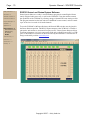
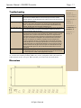
1
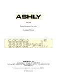
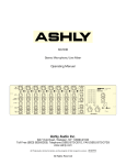
VCM-88C
Eight Channel Matrixing Level Controller
Operating Manual
Ashly Audio Inc.
847 Holt Road, Webster, NY 14580-9103
Toll Free (800) 828-6308, Telephone (585) 872-0010, FAX (585) 872-0739
www.ashly.com
All Trademarks referred to herein, are the property of their respective owners. R-051807
All Rights Reserved
Page - 2
Operator Manual – VCM-88C Controller
This page intentionally left blank
Copyright© 2007 – Ashly Audio Inc.
Operator Manual – VCM-88C Controller
Page - 3
Important Safety Instructions
Consignes de sécurité à lire attentivement
Safety Instructions – 3
Introduction - 4
VCM-88C Controller – 5
Connectors & Cables – 5
Physical Description - 6
Installation – 7
Applications - 8
The lightning flash with arrowhead symbol, within an equilateral triangle, is
intended to alert the user to the presence of uninsulated "dangerous voltage"
within the product's enclosure that may be of sufficient magnitude to constitute a
risk of electric shock to persons. The exclamation point within an equilateral
triangle is intended to alert the user to the presence of important operating and
maintenance instructions in the literature accompanying the device.
1.
2.
3.
4.
5.
6.
7.
8.
9.
10.
11.
12.
13.
14.
15.
Read these instructions.
Keep these instructions.
Heed all warnings.
Follow all instructions.
To reduce the risk of fire or electric shock, do not expose
this apparatus to rain or moisture.
Do not use this apparatus near water.
Clean only with dry cloth.
Do not block any ventilation openings. Install in
accordance with the manufacturer’s instructions.
Do not install near any heat sources such as radiators, heat
registers, stoves, or other apparatus that produce heat.
Do not defeat the safety purpose of the polarized or
grounding-type plug. A polarized plug has two blades
with one wider than the other. A grounding type plug has
two blades and a third grounding prong. The wide blade
or the third prong are provided for your safety. If the
provided plug does not fit into your outlet, consult an
electrician for replacement of the obsolete outlet.
Protect the power cord from being walked on or pinched
particularly at plugs, convenience receptacles, and the
point where they exit from the apparatus.
Only use attachments/accessories specified by the
manufacturer.
Use only with the cart, stand, tripod, bracket, or table
specified by the manufacturer, or sold with the
apparatus. When a cart is used, use caution when
moving the cart/apparatus combination to avoid injury
from tip-over.
Unplug this apparatus during lightning storms or when
unused for long periods of time.
Refer all servicing to qualified service personnel.
Servicing is required when the apparatus has been
damaged in any way, such as power-supply cord or plug
is damaged, liquid has been spilled or objects have fallen
into the apparatus, the apparatus has been exposed to
rain or moisture, does not operate normally, or has been
dropped.
Le symbole de la flèche dans un triangle équilateral symbolisant la foudre est
prévu pour sensibiliser l’utilisateur à la présence de tension de voltage non isolée
à l’intérieur de l’appareil. Elle pourrait constituer un danger de risque de
décharge électrique pour les utilisateurs. Le point d’exclamation dans le triangle
équilatérale alerte l’utilisateur de la présence de consignes qu’il doit d’abord
consulter avant d’utiliser l’appareil.
1.
2.
3.
4.
5.
6.
7.
8.
9.
10.
11.
12.
13.
14.
15.
Lisez ces instructions.
Conservez ces instructions.
Observez les avertissements.
Suivez ces instructions.
Pour réduire le risque de feu ou la décharge électrique,
ne pas exposer cet appareil pour pleuvoir ou l'humidité.
Ne pas utiliser l’appareil près de l’eau.
Le nettoyer à l’aide d’un tissus sec.
Ne pas bloquer les ouvertures de ventilation, installer
selon les consignes du fabricant.
Eloigner des sources de chaleur tel: radiateurs,
fourneaux ou autres appareils qui produisent de la
chaleur.
Ne pas modifier ou amputer le système de la mise à
terre. Une prise avec mise à terre comprend deux lames
dont une plus large ainsi qu’une mise à terre: ne pas la
couper ou la modifier. Si la prise murale n’accepte pas
la fiche, consulter un électricien pour qu’il remplace la
prise désuète.
Protéger le cordon de secteur contre tous bris ou
pincement qui pourraient l’endommager, soit à la fiche
murale ou à l’appareil.
N’employer que les accessoires recommandés par le
fabricant.
N’utiliser qu’avec les systèmes de fixation,chariots,
trépied ou autres, approuvés par le fabricant ou vendus
avec l’appareil.
Débrancher l’appareil lors des orages électriques ou si
inutilisé pendant une longue période de temps.
Un entretient effectué par un centre de service accrédité
est exigé si l’appareil a été endommagé de quelque
façon: si il a été exposé à la pluie,, l’humidité ou s’il ne
fonctionne pas normalement ou qu’il a été échappé.
All Rights Reserved
Data Connections – 9
Troubleshooting – 11
Dimensions - 11
Specifications - 12
Warranty - 13
This manual uses a
Perpetual Table Of
Contents. Each page
has a copy of the
manual’s contents in a
gray box just like this
one. The section you are
in will always be bold
with the other sections
“grayed out.” The feature
allows you to jump
directly to another
section without having to
return to a Table Of
Contents page.
Page - 4
Operator Manual – VCM-88C Controller
Safety Instructions – 3
Introduction - 4
VCM-88C Controller – 5
Connectors & Cables – 5
Physical Description - 6
Installation – 7
Applications - 8
Data Connections – 9
Troubleshooting – 11
Dimensions - 11
Specifications - 12
Warranty - 13
Introduction
Congratulations on your purchase of an Ashly VCM-88C matrixing level controller. In one
compact rack-mount package we have combined features, reliability, and sonic performance
you have come to expect from Ashly. Features of this unit include:
VCA Based Circuitry
Master level range of -75dB to +20dB.
Eight fully-independent VCA channels with:
o Limiting
o Remote level control
o Mixing
Optional control via the Ashly RD-8C (desktop) or RW-8C (wall-mount) remote
controller or Ashly's Protea System Software,
Each VCA channel provides;
o Separate input and output jacks for patching into line-level signal paths
o “pass-through” configuration for daisy chaining multiple units together
About Ashly
Ashly Audio was founded in 1974 by a group of recording engineers, sound professionals,
and electronics designers. The first products were custom consoles for friends and
associates, but business quickly grew. The philosophy established from the very beginning
holds true today: to offer only the highest quality audio tools at an affordable cost to the
professional user – ensuring reliability and long life. More than thirty years later, Ashly
remains committed to these principles.
Copyright© 2007 – Ashly Audio Inc.
Operator Manual – VCM-88C Controller
Page - 5
Safety Instructions – 3
VCM-88C Controller
Introduction - 4
The VCM-88C allows for accurate, low distortion level control without signal degradations
encountered when using mechanical controls or long signal paths. This unit adds
functionality and control in any system or installation where remote control or fast automatic
system response is required. Specific applications are discussed in detail on Page 8.
VCM-88C Controller – 5
Connectors & Cables - 5
Grounding
Physical Description - 6
Installation – 7
Connectors & Cables
Applications - 8
Your VCM-88C is provided with a single connector type for audio signals in and out. All
connections are made via 1/4” stereo phone jacks (TRS), which can be used to connect,
balanced or unbalanced signals to the unit. Whenever possible, balanced connections are
recommend between all components in your system, as this eliminates ground-loop induced
hum and noise.
Data Connections – 9
Troubleshooting – 11
Dimensions - 11
Specifications - 12
Warranty - 13
VCM-88C Audio Connector Polarities
All inputs are 20K ohm active balanced and 10K ohm unbalanced.
Note: The VCM-88C can be connected using a “single connector insert mode.” In this
configuration, the In jack functions as a TRS insert with the Tip receiving the input, the ring
the output and the sleeve acting as a common ground.
Remote control connections are made via Euroblock connectors. Polarities and other details
for those connectors are provided on the chassis.
Unbalanced Connections and Grounding
If you must use unbalanced connectors, the negative lead of the connector (ring) should be
tied to the ground lead (sleeve). Using unbalanced connections could result in chassis
ground-loop noise. Altering the signal/chassis ground relationship in equipment connected
to your unit may eliminate the noise.
All Rights Reserved
Page - 6
Operator Manual – VCM-88C Controller
Safety Instructions – 3
Introduction - 4
VCM-88C Controller – 5
Connectors & Cables - 5
Physical Description
The VCM-88C is 1RU, and weighs 10 pounds.
VCM-88C Front Panel
Physical Description - 6
Front Panel
Rear Panel
Installation – 7
Applications - 8
1.
Data Connections – 9
Troubleshooting – 11
Dimensions - 11
Specifications - 12
Warranty - 13
2.
3.
Power LED – This blue LED indicates when
the unit is powered on. The power switch is one
the rear of the unit. If the blue LED does not
light, check to see if the unit is plugged into a
live outlet, and that the removable AC cord is
firmly plugged in. If there is still no light, refer
the unit to a qualified service technician.
Digital Remote Control Disable Switch - This
switch disables the RD-8C remote controller
and returns all eight channels to unity gain.
This switch is Protea Software selectable to
provide either unity gain or the last level
settings before the remote is disabled. The
adjacent red LED indicates when this switch is
depressed. The nearby green Remote Active
indicator will go off when the remote is disabled
because the RD-8C does not send any data
when it is disabled. After releasing the remote
disable switch, all channels return to their
respective levels set by the RD-8C remote
controller or software control.
Digital Remote Control Status Indicator This green LED indicates when the VCM-88C
is receiving data from the RD-8C, RW-8C, or
computer control. In the event of remote control
data interruption, the VCM-88C will lock all
settings just before the data reception stopped
and continue to operate as if there were no
changes happening. Reconnecting the remote
data signal with the VCM-88C still operating will
instantly change the channel level settings to
wherever the controller is currently set.
4.
5.
6.
Note: The VCM-88E will remember the last
level settings when the AC power is switched
off and will restore these settings on power-up.
Master Attenuation Control - This control
attenuates all eight channels uniformly, and
was designed as a simple means of turning
down all eight audio channels n the event of
feedback or other sound system problems.
Normally this control should be set fully
clockwise at 0dB attenuation.
Signal Present LED - Each channel has a
green LED to indicate input signal present (app.
-20dBu). Since the LED is referencing the
audio signal prior to the VCA circuit, the LED
will continue flashing even if the channel level
is turned down.
Limiter Threshold Control and Indicator The recessed Limiter Threshold trimpot adjusts
the signal threshold above which the limiter will
become active. The units of this threshold dial
are dBu where 0dBu = 0.775Vrms. The limiter
is a peak-detecting true VCA type limiter with
very low distortion. The input to output ratio of
the limiter is approximately 10 to 1 with a
relatively fast attack and moderate release time
behavior. The adjacent yellow threshold LED
indicates when the limiter circuit has been
activated by an audio signal above the
threshold level. To disable the limiter on any
given channel, simply rotate its threshold
adjustment fully clockwise to +23dBu, which is
the maximum input signal of the unit.
Copyright© 2007 – Ashly Audio Inc.
Operator Manual – VCM-88C Controller
Page - 7
Safety Instructions – 3
VCM-88C Rear Panel
Introduction - 4
VCM-88C Controller – 5
Connectors & Cables - 5
1.
2.
3.
4.
5.
DC Control - A 12-position Euroblock
connector is used for DC control of the eight
VCA channels and Master Attenuation,
providing a simple and cost-effective method
for custom control. Most electronics hardware
stores will have the male connector
complement. The reference DC voltage is also
provided, thus requiring only the male
connector, wire, and a 10K ohm potentiometer
for each channel to control audio levels from
any reasonable distance.
Data Protocol Selector - These two DIP
switches allow selection of four data protocols.
The Standard protocol is selected for use with
current AMX, or Crestron controllers. The
Protea Software protocol is selected for use
with Ashly's Protea System Software. The RD
protocol is used for control by an Ashly RD-8C
remote. The Legacy protocol is selected for
control by a legacy Ashly or AMX device.
Device ID Select - Each VCM-88C can be set
to one of 16 addresses, allowing for control of
up to 128 channels (16 x 8) from a single data
line. The device ID on the VCM-88C is selected
in binary format from the Device ID DIP switch
on the rear panel.
RS-232 Input - RS-232 is a bi-directional serial
communications connection which allows
computer devices to control other hardware.
Ashly Protea System Software uses RS-232 to
control the VCM-88C.
Remote Control Data Input - This connector is
used for remote control by the Ashly RD-8C or
RW-8C, or other third party controllers.
6.
7.
8.
9.
RS-232 Mode Switch - The RS-232 mode
switch is pushed in only when the VCM-88C’s
RS-232 Input is connected to a PC, and
another unit is connected to the Slave Data
in/out connector.
Master Output and Channel Pass Through The VCM-88C can be used as an eight-in/one
out remote level control for personal monitor
mixing using the Master Output. Multiple VCM88C units can be daisy chained to produce
several unique mixes from the same program
source. To simplify cabling for this application,
the VCM-88C has the ability to internally pass
each channel’s input signal directly to its output
jack, disabling that channel’s direct VCA output
but eliminating the need for special “Y” cables.
The passed-through channel’s VCA output is
automatically summed to the 200 Ohm
pseudobalanced Master Output along with
other channels for final output. The gain from
any one input channel to Master Output is -6dB
so that a mix of several audio channels will
have approximately the same volume as one of
the input channels. See section 8.2 for channel
pass-through details.
Slave Data In/Out - Multiple VCM-88C units
can be placed in the same control loop using
the Slave Data In/Out euroblock connectors.
Control data originates from another unit under
RS-232 control.
Power Switch - This rocker switch, switches
the AC power to the unit. A blue front-panel
LED indicates when the unit is powered on.
Installation
Always switch the unit off before making substantial changes to the settings or connectors.
Use four screws and washers when rack mounting. This unit has specific electrical and
signal requirements, please take special care to double check all connections and settings and
refer to the specifications section of this manual. The unit should be connected to a standard
3-wire grounded electrical outlet supplying 100-240 Volts, 50-60 Hz. To reduce the risk of
ground loop hum, connect all audio equipment to the same electrical power source. Removal
of the ground pin is both unlawful and dangerous, as a potential shock hazard could result.
Overall power consumption is less than 30 watts.
NOTE: The power switch does NOT isolate the appliance from mains. Make sure the mains
power socket or an alternative disconnect device is near by and easily accessible. When the
product is connected to mains, the line-filter and the input of the fuse are energized.
All Rights Reserved
Physical Description - 6
Front Panel
Rear Panel
Installation – 7
Applications - 8
Data Connections – 9
Troubleshooting – 11
Dimensions - 11
Specifications - 12
Warranty - 13
Page - 8
Operator Manual – VCM-88C Controller
Safety Instructions – 3
Introduction - 4
VCM-88C Controller – 5
Applications & Configurations
Physical Description - 6
To make any configuration changes, the top of the VCM-88C must be removed. Be sure
to disconnect all cables & power before opening the unit. Jumper settings are illustrated in
the table & diagrams below.
Installation – 7
Single Connector Insert
Applications - 8
Insert
Pass-Through
Matrixing
Jumper Settings
To use a mixing console’s single jack insert capabilities with the VCM-88C, an internal
jumper must be selected to properly configure the input and output connections. Once
configured the input is on the tip and the output is on the ring of the In jack. The Out jack
is not used.
Data Connections – 9
Single Channel Pass-Through
Troubleshooting – 11
When Using Master Output for personal monitor mixing or other application, it is possible
to pass a channel’s input directly to it’s output jack, eliminating the need for extra “Y”
cables when daisy-chaining. The VCA circuit’s output signal is still summed to the Master
Output, but is removed from the channel output jack.
Connectors & Cables - 5
Dimensions - 11
Specifications - 12
Warranty - 13
Input/Output Matrixing
Input Matrixing means that an input can be internally routed to one or more additional
channel inputs, particularly useful in distributed zone applications. Each of the matrixed
VCA channels share a common input signal but retain their distinct level controls via the
RD-8C, RW-8C, or other hardware or software controllers.
Jumper
J 05
Pin Description
O
Not Used
T
Bypass VCA on Channel
J 04
V
Enable VCA on Channel
1
Single Jack TRS Insert (T=In, R=Out)
J 02
2
Dual Jack In/Out
P
Not Used
M1
Channel Input Mix Bus 1 Assign
M2
Channel Input Mix Bus 2 Assign
J 07
M3
Channel Input Mix Bus 3 Assign
PT
Channel Input pass-through to VCA
M1
Channel VCA Source Selected from M1 Bus
M2
Channel VCA Source Selected from M2 Bus
J 08
M3
Channel VCA Source Selected from M3 Bus
PT
Channel VCA Source from pass-through input
Default settings in BOLD
Jumper Settings with Signal Flow
Copyright© 2007 – Ashly Audio Inc.
Operator Manual – VCM-88C Controller
Page - 9
Data Connections & Configurations
Safety Instructions – 3
Introduction - 4
Remote Data Control
To connect the RD-8C, RW-8C or other compatible remote controller, the VCM-88C uses
a three-pin euroblock connector. Data can be sent through one channel of a standard audio
snake without affecting adjacent audio channels. Do not use an isolation transformer in the
data line. Connect the three pins to the same pins on the RD-8C/RW-8C remotes as
labeled. Be sure to set the VCM-88C protocol to the RD-8C/RW-8C on the rear panel DIP
switches.
The Standard data protocol is compatible with current AMX and Crestron controllers. Both
AMX and Crestron provide hardware which interfaces with the VCM-88C. To learn more
about their control systems, visit their websites at www.amx.com and www.crestron.com.
VCM-88C Controller – 5
Connectors & Cables - 5
Physical Description - 6
Installation – 7
Applications - 8
Data Connections – 9
Remote Data Control
AMX & Legacy
DC Control
RS-232
Troubleshooting – 11
The details of the Standard VCM-88C protocol are as follows: The three connector pins
are labeled: G (ground), V+ (+20VDC for RD-8c/RW-8C controllers), and D (Data). Do
not use the V+ pin with 3rd party hardware such as AMX or Crestron.
A valid message consists of two bytes with no break between byte1 and byte 2.
1 Byte = start bit + 8 data bits + stop bit (10 bits total, no parity)
Baud rate: 9600 bps
Start bit: logical 0 (current on)
Stop bit: logical 1 (current off)
Byte 1: Channel ID Character:
Byte 2: Channel Level Character:
hex 80 - hex FF = Channels 1 - 128
hex 7F = full on = +20.25dB
hex 64 = unity gain = 0dB
hex 00 = off = -75dB
(step size = 0.75dB)
AMX and Legacy
Older AMX products using the VCX-80 driver, require the Legacy data protocol setting on
the VCM-88C rear panel DIP Switches.
DC Control Voltage Connection
Direct DC voltage control of internal VCA circuits is available on the VCM-88C via a 12
pin euroblock connector. DC control allows for custom “low-tech” hardware interfaces.
Two wires are used to supply positive and negative DC voltage to ordinary 10K ohm
linear-taper potentiometers, and a wire is used to return the wiper of each control to its
respective channel (see pinout below). Telephone wire with eleven conductors or more is a
good choice for this application, and since only DC voltage is used, control line distance is
not a major concern.
Pin 1
Pin 2
Pin 3
Pin 4
Pin 5
Pin 6
Channel 1 DC control input
Channel 2 DC control input
Channel 3 DC control input
Channel 4 DC control input
Channel 5 DC control input
Channel 6 DC control input
Pin 7
Pin 8
Pin 9
Pin 10
Pin 11
Pin 12
Channel 7 DC control input
Channel 8 DC control input
Master DC control input
+15VDC - Connect to pot CCW
(Ground for data input)
-4VDC - Connect to pot CW
All Rights Reserved
Dimensions - 11
Specifications - 12
Warranty - 13
Page - 10
Safety Instructions – 3
Introduction - 4
VCM-88C Controller – 5
Connectors & Cables - 5
Physical Description - 6
Installation – 7
Applications - 8
Data Connections – 9
Remote Data Control
AMX & Legacy
DC Control
RS-232
Troubleshooting – 11
Operator Manual – VCM-88C Controller
RS-232 Control and Protea System Software
Protea System Software is Ashly’s custom Windows program for controlling the Protea
family of digital audio processors, as well as the VCM-88C. Using the software extends
the capabilities of the VCM-88C by allowing storage of channel and scene settings to disk.
The program interface has the look and feel of the RD-8C remote control, and can control
up to 16 devices for a total of 128 audio channels.
To use the VCM-88C with Protea Software, the Protocol DIP switches must be placed in
the Protea Software position. The RS-232 Input connector to the VCM-88C is a D-Sub 9
pin female, and connects to an unused Com port on a PC. Protea System Software allows
Com Port assignment (1-16) in its setup menu. If the only available port on a PC is a USB
port, a USB to RS-232 converter can be used. Protea System Software is available free of
charge on the Ashly website www.ashly.com.
Dimensions - 11
Specifications - 12
Warranty - 13
Copyright© 2007 – Ashly Audio Inc.
Operator Manual – VCM-88C Controller
Page - 11
Safety Instructions – 3
Troubleshooting
Introduction - 4
Situation
Action
VCM-88C Controller – 5
No Output
Check AC power - is blue power LED indicator on? Check input/output connections - are
they reversed? Is the Master Attenuator control turned fully up? Are remote controller
channels switched on? Are the input/output jacks configured correctly (one jack insert versus
two jacks) for the application?
Are the yellow Limiter Threshold indicators on often? Rotate the recessed Threshold controls
clockwise to allow greater output signals to pass unlimited. Check the Master Attenuator
control - normally this control should be fully clockwise at 0dB. Check the RD-8C remote
controller -the fader levels should normally be operated around 8.
Is the peak light flashing? If it is, an overload is occurring within the crossover, and may also
be occurring in other parts of the system. If the peak light is not flashing, the distortion is
occurring somewhere outside the crossover.
Hum and buzz noise is usually caused by a “ground loop” between audio components. Try
using balanced input and output connections between the VCM-88C and other components
in the system. Also, try to power all components in the system from a single AC branch
circuit. Noise can also be caused by a large amount of gain applied to an insufficiently low
input signal. The VCM-88C is not designed to feed microphones directly into the inputs
without a mic preamp first. The VCM-88C is essentially a line level unity-gain device,
meaning it is designed to be fed by a nominal 0dBu line level signal and its output should
typically be 0dBu in level. To ensure proper gain structure in your sound system, press the
remote disable switch in and rotate the Master Attenuator control fully clockwise so that all
VCM-88C channels are at unity gain. Adjust your signal source which precedes the VCM88C for nominal 0dBu signal levels, then push the Remote Disable switch out for remote
controllability.
The maximum input signal level is +23dBu = 10.95Vrms. Above this input level, input
clipping distortion will occur. Also, if the input signal level plus the gain set by the remote
controller goes above +23dBu, output clipping distortion will result.
Connectors & Cables - 5
Very Little Output Signal
Very Little Output Signal
Excessive hum or noise
Distorted Sound
Note: Unshielded cables, improperly wired connections, and cable with broken strands (shorts,
etc.) are the most common problems. Make sure you use good quality cable with connectors
soldered firmly on the correct pin. When in doubt, get in touch with your Ashly dealer.
Dimensions
All Rights Reserved
Physical Description - 6
Installation – 7
Applications - 8
Data Connections – 9
Troubleshooting – 11
Dimensions - 11
Specifications - 12
Warranty - 13
Page - 12
Safety Instructions – 3
Introduction - 4
Operator Manual – VCM-88C Controller
Specifications
VCM-88C
Connectors & Cables - 5
SPECIFICATION
INPUT
Input Type:
Physical Description - 6
Input Impedance:
20K ohm balanced, 10K ohm unbalanced
Installation – 7
Max input level:
VCM-88C Controller – 5
Applications - 8
+23dBu
Input jack may be internally selected as a single in/out insert
Data Connections – 9
CHANNEL OUTPUTS
Output Type:
Troubleshooting – 11
Output Impedance:
Dimensions - 11
1/4" TRS
1/4" TRS
132 ohm servo-balanced, 66 ohm unbalanced
Max output level:
+22dBu
Specifications - 12
MASTER OUTPUT
Output Type:
1/4" TRS
Warranty - 13
Output Impedance:
132 ohm servo-balanced, 66 ohm unbalanced
Max output level:
+22dBu
AUDIO PERFORMANCE
Nominal Gain:
Gain Range:
0dB +/-0.5dB
+20dB to –75dB
Frequency Response:
+/-0.2dB 20Hz-20Khz
THD:
<0.03% at 0dBu, 20Hz-20Khz
Output Hum & Noise:
Crosstalk:
<-90dBu, 20Hz-20KHz unweighted
<-80dB at 20KHz
LIMITER
Threshold Range:
-23dBu to +22dBu
Compression Ratio:
10:1
DATA INPUTS
RD-8C
RS-232
DC Control
Slave Data In/Out
Input Type: Euroblock, pin 3=data, pin 2=+V, pin 1=ground
Data Format: 2Vp raised-cosine
Input Type: D-Sub 9 pin female, pin 3=data, pin 5=ground
1 start, 8 data, 1 stop bits at 9600 baud
Input Type: Euroblock Control Voltage: -4V to +15V provided
for external 10K ohm potentiometers
Type: 6 Pin Euroblock
WEIGHT & POWER
SHIPPING WEIGHT
13 lbs. Maximum
POWER REQUIREMENTS
100-240 Volts, 50-60 Hz, 30 watts
Copyright© 2007 – Ashly Audio Inc.
Operator Manual – VCM-88C Controller
Page - 13
Introduction
Safety
Instructions
-2
–3
Limited Warranty
The PE Series
Introduction
- 4- 3
Warranty service for this unit will be provided by ASHLY AUDIO INC. in accordance with
the following warrant statement.
ASHLY AUDIO INC. warrants to the owner of this product that this product and the
components thereof, will be free from defects in workmanship and materials for a period of
FIVE years from the date of purchase. ASHLY AUDIO INC. (ASHLY AUDIO) will,
without charge, repair or replace, at its option, defective product or component parts upon
prepaid delivery to the factory service department or authorized service center, accompanied
by proof of purchase date in the form of a valid sales receipt. This warranty gives you
specific legal rights, and you may also have other rights which vary from state to state.
EXCLUSIONS: This warranty does not apply in the event of misuse, neglect or as a result of
unauthorized alterations or repairs. This warranty is void if the serial number is altered,
defaced, or removed. ASHLY AUDIO reserves the right to make changes in design or make
additions to or improvements upon this product without any obligation to install the same on
products previously manufactured.
Any implied warranties which may arise under the operation of State law shall be effective
only for FIVE years from the date of purchase of the product. Ashly Audio shall be liable only
to correct defects in the product itself, and not for any damage or injury which may result from
or be incidental to or a consequence of such defect. Some states do not allow either limitations
on how long an implied warranty lasts, or the exclusion or limitation of incidental or
consequential damages, so the above limitations or exclusions may not apply to you.
Obtaining Warranty Service in the United States
For warranty service in the United States, please follow this procedure:
Return the product to Ashly, freight prepaid, with a written statement describing the defect
and application the product is used in. Ashly Audio will examine the product and perform
any necessary service, including replacement of defective parts, at no further cost to you.
Ship your product to:
Ashly Audio Inc.
Attn: Service Department
847 Holt Road
Webster, NY 14580-9103
For units purchased outside The United States of America, service will be provided by an
authorized distributor of ASHLY AUDIO INC.
Obtaining Warranty Service Outside the United States For units purchased outside The
United States of America, service will be provided by an authorized distributor of ASHLY
AUDIO INC.
All Rights Reserved
Physical Description
VCM-88C
Controller -– 45
Installation –&5Cables - 5
Connectors
OperationDescription
Physical
–7
-6
Troubleshooting
Installation
–7 -8
Applications
Spec Table --98
Data Connections
Measurements
- 10– 9
Troubleshooting
Dimensions
- 11 – 11
Dimensions
Warranty
- 12- 11
Specifications - 12
Warranty - 13
Copyright© 2007 – Ashly Audio Inc.