1
GUIDELINES LAID DOWN BY FCC RULES FOR USE OF THE UNIT IN THE
U.S.A. (not applicable to other areas).
NOTICE
This equipment has been tested and found to comply with the limits for a Class
B digital device, pursuant to Part 15 of the FCC Rules. These limits are designed to provide reasonable protection against harmful interference in a residential installation. This equipment generates, uses and can radiate radio frequency energy and, if not installed and used in accordance with the instructions,
may cause harmful interference to radio communications. However, there is no
guarantee that interference will not occur in a particular installation. If this equipment does cause harmful interference to radio or television reception, which can
be determined by turning the equipment off and on, the user is encouraged to try
to correct the interference by one or more of the following measures:
• Reorient or relocate the receiving antenna.
• Increase the separation between the equipment and receiver.
• Connect the equipment into an outlet on a circuit different from that to which the
receiver is connected.
• Consult the dealer or an experienced radio/TV technician for help.
FCC WARNING
Changes or modifications not expressly approved by the party responsible for
compliance could void the user’s authority to operate the equipment.
Proper connectors must be used for connection to host computer and/or peripherals in order to meet FCC emission limits.
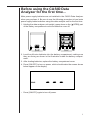
Connector SB-62
Data Analyzer Unit to Power Graphic Unit
Important!
Please keep your manual and all information handy for future reference.
In no event shall CASIO Computer Co., Ltd. be liable to anyone for special, collateral,
incidental, or consequential damages in connection with or arising out of the purchase or
use of these materials. Moreover, CASIO Computer Co., Ltd. shall not be liable for any
claim of any kind whatsoever against the use of these materials by any other party.
• The contents of this manual are subject to change without notice.
• No part of this manual may be reproduced in any form without the express written
consent of the manufacturer.
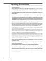
Before using the CASIO Data
Analyzer for the first time...
Main power supply batteries are not installed in the CASIO Data Analyzer
when you purchase it. Be sure to use the following procedure to load main
power supply batteries before using this data analyzer unit for the first time.
1. Holding the data analyzer unit upright, press down on the {▲OPEN} part
of the battery compartment cover and slide the cover off.
2. Load four AA-size batteries into the battery compartment, making sure
they are facing as shown in the illustration inside the battery compartment.
3. After loading batteries, replace the battery compartment cover.
4. Press [ON/OFF] to turn on power, which should make the screen shown
below appear on the display.
• Press [ON/OFF] again to turn off power.
i
Handling Precautions
• Never insert a probe into an electrical outlet. Doing so creates the danger
of electrical shock.
• Never apply more than 30V to the analog channels (CH1, CH2, CH3), or
more than 5.5V to the SONIC, DIG IN, or DIG OUT channels. Doing so
can damage the data analyzer.
• Your data analyzer unit is made up of precision components. Never try to
take it apart.
• Avoid dropping your data analyzer unit and otherwise subjecting it to strong
impact.
• Do not store the data analyzer unit or leave it in areas exposed to high
temperatures or humidity, or large amounts of dust. When exposed to low
temperatures, the data analyzer unit may require more time to display
results and may even fail to operate. Correct operation will resume once
the data analyzer unit is brought back to normal temperature.
• Replace the main batteries once every 2 years regardless of how much
the data analyzer unit is used during that period. Never leave dead batteries in the battery compartment. They can leak and damage the unit.
• Keep batteries out of the reach of small children. If swallowed, consult
with a physician immediately.
• Avoid using volatile liquids such as thinner or benzine to clean the unit.
Wipe it with a soft, dry cloth, or with a cloth that has been dipped in a
solution of water and a neutral detergent and wrung out.
• In no event will the manufacturer and its suppliers be liable to you or any
other person for any damages, expenses, lost profits, lost savings or any
other damages arising out of loss of data arising out of malfunction, repairs, or battery replacement. The user should prepare physical records
of data to protect against such data loss.
• Never dispose of batteries, the liquid crystal panel, or other components
by burning them.
• When the “Low batt.” message appears on the display, replace the batteries as soon as possible.
• Be sure that the power is turned OFF when replacing batteries.
• Using the data analyzer unit near a television or radio can cause interference with TV or radio reception.
• Before assuming malfunction of the unit, be sure to carefully reread this
manual and ensure that the problem is not due to insufficient battery power
or operational errors.
ii
Contents
Chapter 1: Getting Ready .................................. 1
Unpacking .................................................................................... 2
Probes ........................................................................................... 2
CASIO Data Analyzer Overview ................................................. 3
Sample Data ................................................................................. 3
Probes ........................................................................................... 3
Channels ....................................................................................... 3
Data Analyzer and the CFX-9850G/CFX-9800G .......................... 3
Command and Programs .............................................................. 4
Conversion Equations and Post-processing .................................. 4
Data Filtering ................................................................................. 5
Keyboard ...................................................................................... 5
Data Analyzer Unit ........................................................................ 5
Key Functions ................................................................................ 6
Reading the Display .................................................................... 8
Display Panel ................................................................................ 8
Display Screen Areas .................................................................... 8
Out-of-Range Samples ................................................................. 9
Power Supply ............................................................................. 10
Batteries ...................................................................................... 10
Battery Replacement Interval ...................................................... 11
Auto Power Off ............................................................................ 11
Optional AC Adaptor ................................................................... 11
Connecting the Data Analyzer to a Calculator ....................... 13
Connecting a Probe .................................................................. 13
About Input Channels .................................................................. 13
Analog Input Channels ................................................................ 14
Ultrasonic Input Channel ............................................................. 14
Digital Input/Output Channel ....................................................... 14
iii
Chapter 2: Modes ............................................. 15
Relationships Between Modes .................................................... 16
Communications Mode ............................................................... 17
Multimeter Mode ......................................................................... 17
Internal Mode .............................................................................. 18
Data-Log Mode ........................................................................... 19
Setup Mode ................................................................................. 20
Auto-ID Probes ............................................................................ 21
Chapter 3: Commands and Programming ..... 23
Command Conventions and Formats ..................................... 24
Commands .................................................................................. 24
Initial Settings .............................................................................. 25
Programming ............................................................................. 26
Tasks Normally Controlled by Programs ..................................... 26
Example Program ....................................................................... 27
Sending Commands from a Calculator
to the Data Analyzer ........................................................... 27
Sending List Data with the CFX-9850G “Send(” Command ........ 27
Send(List) Examples ................................................................... 28
Sending Matrix Data with the CFX-9800G LINK Mode ............... 28
Matrix Data Example ................................................................... 29
Transferring Sampled Data to a Calculator ............................ 30
Transferring Data to the CFX-9850G........................................... 30
Post-processing Off ..................................................................... 30
Post-processing On ..................................................................... 30
Sample Program Using Receive(Variable) .................................. 31
Sample Operation Using Receive(List) ....................................... 32
Fetching Data Using Receive(Matrix) .......................................... 32
Sample Operation Using Receive(Matrix) ................................... 32
Using Receive(List) to Fetch Sampled Data and
Stat Post-Processing Data ................................................... 32
Sample Operation Using Receive(List) to
Fetch Sampled Data and Stat Post-Processed Data ........... 33
Using Receive(List) to Fetch Statistical Post-Processed Data .... 34
Using Receive( to Fetch Time Data ............................................. 35
Transferring Data to the CFX-9800G........................................... 35
Example CFX-9800G Operation Following Data Transfer ........... 36
iv
Command Reference ................................................................ 36
Command 0 - All Clear ................................................................ 36
Command 1 - CHANNEL SETUP ............................................... 37
Command 2 - DATA TYPE AND DISPLAY SETUP ..................... 43
Command 3 - SAMPLE AND TRIGGER SETUP ........................ 45
Command 4 - CONVERSION EQUATION SETUP ..................... 50
Command 5 - DATA RANGE SETUP .......................................... 52
Command 6 - MULTIMETER MODE SETUP .............................. 54
Command 7 - REQUEST STATUS .............................................. 56
Command 8 - SAMPLING START ............................................... 56
Command 9 - PROBE CALIBRATE ............................................ 57
Appendix A: Technical Reference .................. 61
Error Messages ......................................................................... 62
Probes ........................................................................................ 62
Light Probe .................................................................................. 62
Light Probe Specifications ........................................................... 62
Temperature Probe ..................................................................... 63
Temperature Probe Specifications .............................................. 63
Voltage Probe .............................................................................. 63
Voltage Probe Specifications ...................................................... 63
Probe Precautions ....................................................................... 64
Auto-ID Probe.............................................................................. 64
Connector Pinouts ....................................................................... 65
Conversion Equations .............................................................. 66
Command 4 Type, Form, and Restrictions .................................. 66
Other Technical Information ..................................................... 67
Clock-In Line Operation ............................................................... 67
Clock-Out Line Operation ............................................................ 67
Digital Output Buffer .................................................................... 67
Digital Output Buffer Example ..................................................... 67
Period and Frequency Measurement .......................................... 68
Hard Trigger ................................................................................. 69
Soft Trigger .................................................................................. 69
v
Appendix B: Command Tables ....................... 71
Command 1 - CHANNEL SETUP ............................................... 72
Command 2 - DATA TYPE AND DISPLAY SETUP ..................... 73
Command 3 - SAMPLE AND TRIGGER SETUP ........................ 74
Command 4 - CONVERSION EQUATION SETUP ..................... 75
Command 5 - DATA RANGE SETUP .......................................... 76
Command 6 - MULTIMETER MODE SETUP .............................. 76
Appendix C: Troubleshooting/
Other Information ........................................ 77
Troubleshooting ........................................................................... 78
Specifications .............................................................................. 79
Manual Conventions
The following are the conventions used in this manual to indicate key cap
markings, precautions, etc.
• Markings on the key caps of the data analyzer unit and the connected
graphic scientific calculator are indicated by square brackets. Examples:
[ON/OFF], [MODE].
• Precautions, reference pages, and supplementary information are indicated using the following icons.
P.00
Reference pages
Precautionary and important information that requires attention
Supplementary information
• This manual covers operation with the CASIO CFX-9850G and CFX-9800G
graphic scientific calculator models. All operations described for the CFX9850G also apply to the CFX-9950G. See the explanations for CFX-9850G
procedures for information on how to operate the CFX-9950G.
• All references to “the calculator” in this manual refer to the CFX-9850G,
CFX-9950G or CFX-9800G graphic scientific calculator.
vi