1
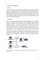
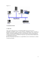
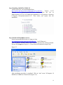
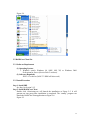
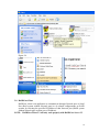
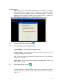
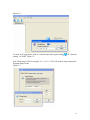
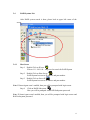
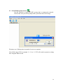
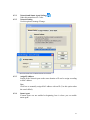
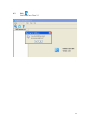
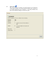
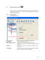
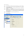
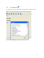
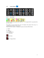
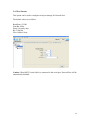
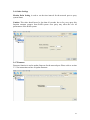
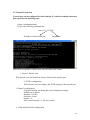
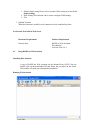
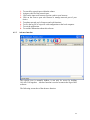
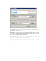
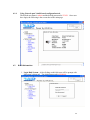
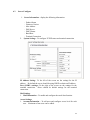
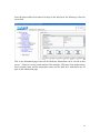
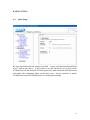
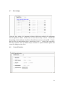
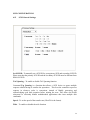
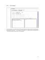
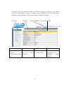
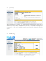
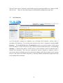
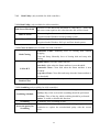
RAIDCare 2.3 User Manual
NOTE:
RAIDCare Client 2.3 will only work properly with RAIDCare Server 2.3
5
1.0 INTRODUCTION TO RAIDCARE ......................................................................... 9
1.1 TARGET .......................................................................................................................... 9
1.2 ARCHITECTURE .............................................................................................................. 9
2.0 INSTALLATION GUIDE ........................................................................................ 10
2.1 HOST SITE .................................................................................................................... 10
2.1.1 SOFTWARE REQUIREMENT..................................................................................... 11
2.1.2 INSTALLING PROCEDURES ..................................................................................... 11
2.2 RAIDCARE CLIENT SITE ............................................................................................. 13
2.2.1 SOFTWARE REQUIREMENT..................................................................................... 13
2.2.2 INSTALL PROCEDURE............................................................................................. 13
3.0
RAIDCARE CLIENT............................................................................................ 14
3.1 SMART AGENT .............................................................................................................. 15
3.2
NETWORK AND SMART AGENT SETTING ............................................................... 15
3.2.1 NETWORK SETTING, ASSIGN IP ADDRESS, NEW ................................................. 15
3.3
SEARCH RAID SYSTEM ON LAN ........................................................................... 15
3.4
RAID SYSTEMS LIST ............................................................................................ 17
3.4.1 HOST SERVER..................................................................................................... 17
3.4.2 NETWORK PORT ................................................................................................. 18
4.0
RAIDCARE CLIENT 2.3 MENU BAR ............................................................... 19
4.1
SEARCH RAID SYSTEM ON LAN ............................................................................ 20
4.2.1 NETWORK AND SMART AGENT SETTING ............................................................ 21
4.2.2 NETWORK SETTING ............................................................................................ 21
4.2.3 ASSIGN IP ADDRESS ........................................................................................... 21
4.2.4 SMART AGENT ................................................................................................... 21
4.3
EXIT ..................................................................................................................... 22
4.4
QUICK SETUP ........................................................................................................ 23
4.5
RAID CONFIGURATION SETUP ............................................................................. 24
4.5.1 GENERAL PARAMS ............................................................................................. 24
4.5.2 GENERAL SETTING ............................................................................................. 25
4.5.3 SLICE ................................................................................................................. 26
4.5.4 DISK MODE ........................................................................................................ 27
4.6
FC CONFIGURATION SETUP .................................................................................. 28
4.6.1 GENERAL SETUP ................................................................................................ 28
4.6.2 LUN MAP ........................................................................................................... 28
6
4.7
SCSI CONFIGURATION SETUP............................................................................... 29
4.7.1 GENERAL SETUP ................................................................................................ 29
4.7.2 LUN MAP......................................................................................................... 29
4.8
RS232 CONFIGURATION SETUP ............................................................................. 30
4.8.1 MODEM PORT .................................................................................................... 30
4.8.2 TERMINAL PORT................................................................................................. 30
4.9
RAID SYSTEM SETUP ........................................................................................... 31
4.9.1 RTC (ONLY AVAILABLE 8990 CONTROLLER) .......................................................... 31
4.9.2 UTILITY CONFIGURATION (ONLY AVAILABLE 8990 CONTROLLER) ......................... 31
4.9.3 CLONE & SMART (ONLY AVAILABLE 8990 CONTROLLER)....................................... 31
4.9.4 SCRUBBING (ONLY AVAILABLE 8990 CONTROLLER)............................................... 32
4.9.5 PASSWD INFO ........................................................................................................ 32
4.9.7 OTHER INFORMATION ............................................................................................ 32
4.10
NVRAM SETUP ................................................................................................... 33
4.10.1 GENERAL SETTING .............................................................................................. 33
4.10.2 UPDATE FIRMWARE (ONLY AVAILABLE 8990 CONTROLLER)................................. 33
4.11
SAVE CONFIGURATION .......................................................................................... 34
4.12
SYSTEM MONITOR ................................................................................................ 35
4.12.1 COLOR TABLE .................................................................................................. 35
4.12.2 SYSTEM INFORMATION WINDOW ..................................................................... 36
4.12.3 SYSTEM INFORMATION CONFIGURE WINDOW (WITHOUT NETWORK PORT)........ 36
4.12.4 SYSTEM INFORMATION CONFIGURE WINDOW FOR NETWORK PORT .................. 37
4.12.4 SYSTEM INFORMATION CONFIGURE WINDOW FOR NETWORK PORT .................. 37
5.0
INTRODUCTION TO NETWORK PORT......................................................... 38
5.1 INSTALLATION GUIDE ................................................................................................... 38
5.1.1 REQUIREMENTS ......................................................................................................... 38
5.2 QUICK SETUP ............................................................................................................... 38
5.3 OPERATING................................................................................................................... 38
5.3.1 UPDATING FIRMWARE ........................................................................................... 38
5.3.2 UPDATING FIRMWARE BY USING FTP. ..................................................................... 38
5.3.3 UPDATING FIRMWARE BY USING RAIDCARE CLIENT. ........................................... 39
5.4 NETWORK PORT SETTING ............................................................................................. 40
5.4.1 ACCOUNT INFORMATION ....................................................................................... 40
5.4.2 EMAIL INFORMATION ............................................................................................ 40
5.4.3 WEB ACCESS ......................................................................................................... 41
5.4.4 IP ADDRESS SETTING ............................................................................................ 41
5.4.5 PORT PARAMS ....................................................................................................... 42
5.4.6 OTHER SETTINGS .................................................................................................. 43
5.4.7 FIRMWARE............................................................................................................. 43
5.5 TERMINAL CONNECTION .............................................................................................. 44
7
6.0 NETWORK PORT BUILT IN WEB SERVER ..................................................... 45
6.1 USING RAIDCARE WEB ASSISTANT ........................................................................ 45
6.1.2 ADVANCE FUNCTION ......................................................................................... 46
6.1.4
USING NETWORK PORT’S BUILD IN WEB CONFIGURATION TOOL. ................... 48
6.2 RAID INFORMATION: ............................................................................................... 48
6.3 SERVER CONFIGURE ................................................................................................. 49
6.4 QUICK SETUP ........................................................................................................... 51
6.5 NVRAM FUNCTION................................................................................................. 52
6.6 RAID SETTINGS ....................................................................................................... 53
6.7 SLICE SETTINGS ....................................................................................................... 54
6.8
GENERAL FUNCTION ............................................................................................... 54
6.9 TERMINAL PORT SETTINGS ....................................................................................... 55
6.10 SECURITY SETTINGS ............................................................................................... 55
6.11 SCSI GENERAL SETTINGS ...................................................................................... 56
6.11.1 LUN SETTINGS ............................................................................................... 57
7.0
RAIDCARE WEB MANAGER........................................................................... 58
7.1.1 INSTALLING JAVA 2 SDK................................................................................. 58
7.1.2 INSTALLING JAKARTA-TOMCAT ......................................................................... 58
7.1.3 INSTALLING WEB MANAGER.............................................................................. 58
7.2
STARTING WEB MANAGER .................................................................................... 59
7.3 GETTING INTO RAIDCARE WEB .............................................................................. 60
7.4 MAIN PAGE .............................................................................................................. 61
7.5 QUICK SETUP ........................................................................................................... 63
7.6 RAID CONFIG .......................................................................................................... 63
7.7 SCSI INTERFACE ...................................................................................................... 64
7.8
RS232 PARAMS ...................................................................................................... 65
7.9 SYSTEM PARAMS...................................................................................................... 65
7.9.1 COMPANY INFORMATION ....................................................................................... 66
7.9.2 PASSWORD INFORMATION ..................................................................................... 66
7.9.3 MODEM INIT STR .................................................................................................. 66
7.9.4 RTC (ONLY AVAILABLE 8990 CONTROLLER) .......................................................... 66
7.10 NVRAM................................................................................................................ 67
7.11 LOG EVENT ............................................................................................................ 68
7.12 DISK UTILITY (ONLY AVAILABLE FOR 8990 CONTROLLER)...................................... 69
7.12.1 DISK UTILITY (ONLY AVAILABLE FOR 8990 CONTROLLER)................................... 69
7.12.2 CLONE & SMART (ONLY AVAILABLE FOR 8990 CONTROLLER).............................. 69
7.12.3 SCRUBBING (ONLY AVAILABLE FOR 8990 CONTROLLER) ...................................... 69
7.13 CONFIGURATION QUICK DIAGRAM .............................................................................. 70
8
1.0 Introduction to RAIDCare
1.1 Target
RAIDCare Manager, a user-friendly graphical management tool provides a comfortable
interface to configure and monitor the AXUS Brownie RAID/Demon RAID from
anywhere using standard Web browser or RAIDCare Client via a RAIDCare Server or
network port. The friendly interface not only enables the user to monitor and maintain the
Brownie/Demon RAID, but also provides its user advanced functionalities of “Critical
event notification” to report the event via E-mail. RAIDCare Manager is made by AXUS
and only supports AXUS Brownie/Demon series; we do not take responsibilities for any
data lost due to illegal authorization.
1.2 Architecture
There are two members in the architecture of RAIDCare Manager, one called “RAIDCare
Server“, and its counterpart called “RAIDCare Client”. The RAIDCare Server is installed
on the server computer, which is connected directly to Brownie Subsystem via SCSI
cable/FC cable/RS-232. Network Port can act like RAIDCare Sever; therefore
RAIDCare Server is no longer needed on Demon series. Network Port is now a
standard on AXUS Demon series. The RAIDCare Client can be run on any PC system /
SUN system/ Linux System with TCP/IP communication. The RAIDCare Server is
running at Host Server for monitoring RAID’s real-time health status, responding for any
abnormal happens, and accepting RAIDCare Client’s request to reply RAID’s
information or re-configure it. The RAIDCare Client, running at client computer, is a user
interface, which displays the RAID’s information and provides user functions to submit
commands to re-configure the RAID. RAIDCare Client must be the same version as the
RAIDCare server in order for them to communicate. Please see block diagram as below,
Figure 1-1:
We also provide the web interface for managing the RAID; it is shown as below (see
Figure 1-2)
9
Figure 1-2
2.0 Installation Guide
2.1 Host Site
This section will teach you how to install the RAIDCare Server on host server.
Installation of RaidCare Server is not necessary if RAIDCare Server is hosted on
Brownie and Demon systems with build in Network port module. The Network port
module is integrated with RAIDCare Server and also built-in a network monitoring port.
A: Please go to Section 2.2.2 RAIDCare Client Site if your Brownie/Demon Raid system
is with Network port module.
B: Please follow below procedures to set up RAIDCare Server if the Brownie is without
Network port Module.
10
2.1.1 Software Requirement
(1) Operating System
Windows 2000 all version (Service Pack 2 or above)
Windows XP all version
Windows 2003 all version
Linux
Solaris
(2) Addition Software Required
JRE (Java Runtime Environment) 1.4.2 or above
JAVA 2 SDK (a must to run web manager)
JAKARTA-TOMCAT (a must when running RAIDCare Web)
(3) To be fully compatible with RAIDCare 2.3, required firmware is listed below. Later
release firmware will also work.
Brownie
BR8000 BR8000P BR8600 BR1200 BR1200p BR1600 BR1600p
1.20a
1.09p
1.16a
2.20a
2.09p
6.11a
6.09p
Demon
PA-16
PA-08
SA-16
SA-16p
PA-16p
6.08p
1.08p
6.02a
6.06s
6.06s
2.1.2 Installing Procedures
Step 1 Installing JRE.
JAVA™ 2 Runtime Environment, can be downloaded from
http://java.sun.com/j2se/1.4.2/download.html (Figure 2-1). Launch the j2re-xxx.exe
will install JRE automatically and there is no other configuration needed while
installing. If you have any problems during installation, please refer to
http://java.sun.com/j2se/1.4.2/
Open a DOS prompt and type in command “java” to test if your JRE is successfully
installed.
Figure 2-1
11
Step 2 Installing JAKARTA-TOMCAT
Tomcat web server, can be downloaded from
http://apache.cdpa.nsysu.edu.tw/jakarta/tomcat-5/v5.0.27/bin/,
Tomcat
5.0.27
filename is : jakarta-tomcat-5.0.27.exe. Double click the file of
jakarta-tomcat-5.0.27.exe will launch the installation. It will generate a directory
C:\Program Files\jakarta-tomcat-5.0.27. Then reboot your system after the
installation.
Step 3 Install AXUS RAIDCare Server.
Please download RAIDCareServer_Setup.exe from
ftp://raid:[email protected]/RAIDCare/ (use IE Browser).
After download is finished, double click on this file and four files will be generated.
Execute file Setup.exe as Figure 2-3. Please follow the instruction step by step.
Figure 2-3
After installation procedure is completed. Click on “start” menu Æ Programs Æ
RAIDCare Æ RaidCare Client Server (Figure 2-4).
12
Figure 2-4
2.2 RAIDCare Client Site
2.2.1 Software Requirement
(1) Operating System:
1. Windows serials: Windows 98, 98SE, ME, XP, or Windows 2000
Professional or Server (Service Pack 2 or above).
(2) Software (Required):
JRE 1.4.2 or above (JAVA™ 2 SDK will also work)
2.2.2 Install Procedure
Step 1: Install JRE
See Step1 in Section 2.1.2
Step 2: Install RAIDCare Client
Double click \client\setup.exe will launch the installation as Figure 2-5. It will
generate an icon group after installation is completed. The “startup” program can
launch the RAIDCare client application as Figure 2-6.
Figure 2-5
13
Figure 2-6
3.0 RAIDCare Client
RAIDCare client is an application to communicate through Network port or Serial
Port (Raid system without Network port) to do related configurations on RAID
systems by selecting the specified IP address of that Network port (RAID system
without Network port use host server IP address).
NOTE: RAIDCare Client 2.3 will only work properly with RAIDCare Server 2.3
14
3.1 Smart Agent
With Smart agent’s smart login, administrator can monitor or configure
different RAID system without re-login. Smart agent will remember one set
of password when the “enable save user’s information function” is checked.
Jumping from one system to another is now easier then ever. Default user
name “admin”, default password “123456”. Figure 3-1
3.2
Network and Smart Agent Setting
3.2.1
Network Setting, Assign IP Address, New
Network Setting - Use this option to manage IP range.
Assign IP Address - Search all the Network port on the same domain, or IP can
be assign according to MAC address.
New – Click here to manually assign MAC address with an IP. (Use this option
when the search failed).
Smart Agent – If smart agent was not enabled at beginning, here is where you
can enable smart agent.
3.3
Search Raid system on LAN
Use this function to search all RAID systems that is connected to network.
Click on this icon you will be prompt with a pull down menu for IP range.
(Figure 3-2)
15
Figure 3-2
To enter an IP rage please click on “network and smart agent setting”
setting” Æ “ADD” Figure 3-3
Æ “Network
Note: Wide range of IP, for example: 1.1.1.1 to 1.1.1.255 will result in long waiting time.
Program did not crash.
Figure 3-3
16
3.4
RAID Systems List
After RAID system search is done, please look at upper left corner of the
screen.
3.4.1
Host Server
Step 1.
Double Click on IP area:
IP Area 1.1.1.190~190 – range used to search for RAID System
Step 2.
Double Click on Host Server:
RAID System host server IP address and port number.
Step 3.
Double Click on Server IP
RAID System host server IP address and port number.
Note: If Smart Agent wasn’t enabled, then you will be prompted with login screen.
Step 4.
Click on RAID Subsystem.
Here you will be prompted with RAID Subsystem password.
Note: If Smart Agent wasn’t enabled, then you will be prompted with login screen and
RAID subsystem password.
17
3.4.2
Network Port
Please refer to section 5 for a more detail description of network port.
Step 1.
Double Click on Network Port:
IP Area 1.1.1.190~190 – range used to search for RAID System
Step 2. Double Click on IP address
RAID System host IP address and port.
Note: If Smart Agent wasn’t enabled, then you will be prompted with login screen.
Step 3.
Click on RAID Subsystem.
Here you will be prompted with RAID Subsystem password.
Note: If Smart Agent wasn’t enabled, then you will be prompted with login screen and
RAID subsystem password.
The difference between host server and network port:
Host server- RAID system that is locally hosted Without Network port
Network Port - A range of IP address, where RAID systems are connected through LAN
with Network port.
18
4.0 RaidCare Client 2.3 Menu Bar
1.
Search RAID system on LAN - Search a range of IP for RAID system
that is connected on LAN
2.
Network Setting and Smart Agent - Manage IP range to search and
enable/disable smart agent
3.
Exit - Exit RAIDCare Client 2.1
4.
Quick setup - Setting up RAID level without configuring any setups
5.
RAID Configuration Setup - RAID setup configuration
6.
Fiber Card Configuration - To configure fiber card
7.
SCSI Card Configuration - To configure SCSI card
8.
RS232 Configuration - To configure RS232 Serial port connection
9.
RAID System Configuration - To set password and company information
10.
NVRAM Setup - Update, Erase, Restart NVRAM
11.
Save Configuration - To save current RAID setting and HD information
12.
Monitor – Monitor current RAID activities
19
4.1 Search Raid system on LAN
Use this function to search all RAID systems that is connected to network.
Click on this icon you will be prompt with a pull down menu for IP range.
Wait time (sec): Waiting time in seconds, for server to response.
Note: Wide range of IP, for example: 1.1.1.1 to 1.1.1.255 will result in extensive waiting
time. Program did not crash.
20
4.2.1
4.2.2
4.2.3
Network and Smart Agent Setting
Under this menu there are 3 tabs
Network Setting
Use this option to manage IP range.
Assign IP Address
Search all the Network port on the same domain or IP can be assign according
to MAC address.
New
Click here to manually assign MAC address with an IP. (Use this option when
the search failed).
4.2.4
Smart Agent
If smart agent was not enabled at beginning, here is where you can enable
smart agent.
21
4.3
Exit
Exit RAIDCare Client 2.3
22
4.4
Quick setup
This is the easiest way to configure your RAID subsystem, but all parameters
will be setup as defaults. If you wish to change the default value, you’ll have to
go to RAID Configuration icon to customize it. After setup is finished, a hot
spare can be obtained by adding a new HD to the system.
23
4.5
RAID Configuration Setup
This tool allows user to manually setup RAID system by choosing RAID level,
number of HD, and slice size. There are four main categories within RAID
configuration setup menu.
4.5.1
General Params
Basic RAID level setup
Re-config Raid
RAID Level
Disk Number in RAID
Strip Size
Write Buffer
Used to change an existing RAID configuration.
Used to specify the RAID level.
Used to specify the number of disks in the array.
The number is based on the number of physical disks
installed.
Used to specify the size of the stripe in blocks (1 block =
512 bytes).
Used to buffer writes operations using memory. This helps
improve the write performance for RAID 5
24
Steps to setup Array.
Step 1.
Step 2.
In the RAID Array pull down menu, choose which array you wish to configure.
After array number is selected, Check Re-Config RAID check box to begin the
configuring RAID system.
Step 3. After Re-Config RAID is checked, the pull down menu next to RAID level
should be
available.
Step 4. After RAID level is selected, the pull down menu next to Disk Number in RAID
should be available. This is where a user chooses how many hard drives they
wish to use in the array. A spare should always be considered for backup in
case of HD failure.
Step 5. Click on Submit, located on the lower right of the screen.
4.5.2
General Setting
RAID subsystem setup
25
Init R5/R3
Used when configuring a disk group for RAID Level 5. During an
initial RAID 5 configuration, this is automatically executed.
R5/R3 Check
Used to verify the RAID 5 configuration. This option should be
executed when initially configuring for RAID 5.
Beeper
Used to turn on or off the audible alarm when an error occurs or
during an Init RAID 5, R5 Check.
Stop Modem
Used to stop a Page or FAX notification from being sent. Use to stop
receiving the same Page or FAX notification after the initial one has
been acknowledged.
Expand Array
Used this option to increase the disk numbers to an existing
configuration. This feature can increase the array’s capacity without
backup and restore the database.
4.5.3
Slice
Slice is used to divide the RAID capacity to several separated Slices. Maximum
8 of Slices can be set at same time.
26
4.5.4
Disk Mode
Use to enable the Ultra DMA data transfer mode of the RAID subsystem with the
installed disks during initialization.
Disk Mode
Option
IDE DMA Mode
Description:
Setting
Default Setting
0, 1, 2, 3, 4, 5
5
Use to negotiate the highest DMA data transfer mode
with the installed disks during initialization.
Option
IDE LBA Mode
Description:
Setting
Default Setting
Enable, Disable
Enable
Use to enable the LBA feature. The feature allows
BROWNIE to manage large size disk.
Option
IDE Ultra DMA
Description:
Setting
Default Setting
Enable, Disable
Enable
Use to enable the Ultra DMA data transfer mode of the
RAID subsystem with the installed disks during
initialization.
27
4.6
FC Configuration Setup
4.6.1
General Setup
4.6.2
Primary Fiber
Submenu for configuring primary fiber settings
Hard Loop
Enable hard loop ID if you wish to enter the ID manually.
Disable to have the ID set by the controller (Default: Disable)
ID Setup
Enter the hard loop Id for this controller (only hard loop ID is
enabled) Connection Mode Arbitration Loop or Point-to-Point
(default: Arbitration Loop).
Data Rate
1 Giga-bits, 2 Giga-bits (Default:
Auto-negotiated).
Lun Map
Lun Map is used to setup each Slice to map a logical Lun Number.
28
4.7
SCSI Configuration Setup
An SCSI Interface contains two channels, one is Primary SCSI Interface, and
the other is Secondary SCSI Interface. You can drop the pop-up menu to select
a channel to configure SCSI Interface.
The Set SCSI ID and the Termination must be set to avoid causing a conflict
with the SCSI adapter or other SCSI device daisy chained with the RAID
subsystem. Command Tag Queuing is a function that allows a SCSI device to
queue multiple requests without having to serialize the operations. This frees
the controller to process requests in whatever order is convenient, instead of
blindly processing and acknowledging each disk operation before starting the
next. This allows the RAID subsystem to efficiently handle multithreaded
applications that issue multiple disk commands.
4.7.1
General Setup
Primary SCSI
Submenu for configuring primary SCSI settings
Set SCSI ID
Select 0 to 14 or multiple (default: 0). ID 7 is reserved for the
SCSI Card.
Terminating
Enable the SCSI termination of the RAID subsystem.
Tag queuing
Tag queuing allows RAID systems to process multiple requests
from the host without having to serialize the operations thus
improving performance
Speed
Ultra 3, Ultra 2, or Fast (default:
Wide
Use to enable the Ultra/Fast Wide SCSI feature. This feature
allows to increasing the I/O speed on host Interface from SCSI
to Wide SCSI.
4.7.2
Ultra 3).
LUN MAP
Lun mapping is used to setup each Slice to map to a logical Lun Number.
29
4.8 RS232 Configuration setup
The RS232 Params configures the external ports of the RAID subsystem. The RAID
subsystem can communicate with a remote terminal and modem. The RAID subsystem
and the remote terminal must be set to the same communication settings (Baud Rate,
Stop Bit, Data Bit, and Parity).
4.8.1
Modem Port
Option
Set Modem Port Now
Sub-Option
Setting
Default Setting
2400, 4800, 9600, 19200, 38400, 38400
Baud Rate
57600, 115200
1, 2
1
Stop Bit
7, 8
8
Data Bit
None, Odd, Even
None
Parity
Description:
Use to specify the communication protocol between the RAID
subsystem and external modem.
4.8.2
Terminal Port
Option
Set Terminal Port Now
Sub-Options
Settings
Default Settings
2400, 4800, 9600, 19200, 38400, 19200
Baud Rate
57600, 115200
1, 2
1
Stop Bit
7, 8
8
Data Bit
None, Odd, Even
None
Parity
Description:
Use to specify the communication protocol between the RAID
subsystem and remote terminal or terminal emulation software.
The settings on the remote terminal must match the settings of the
RAID subsystem.
30
4.9
RAID System Setup
4.9.1 RTC (only available 8990 controller)
RTC Stands for Real Time Clock. It is used for setting the time on the controller.
Setting the correct time plays an important role in the system administration. Helps the
administrators to keep accurate record of when the event actually occurs.
4.9.2 Utility Configuration (only available 8990 controller)
Clone
Swap
Unit Per Sector
Reduce Read Retry
16 Bytes CDB
Is used to set the bad sector threshold of a hard drive.
When the bad sector count equals to this value then the disk
will be cloned.
Is used to set the bad sector threshold of a hard drive.
When the bad sector count equals to this value then the disk
will be replaced with a pre-cloned disk. To function
properly this value must be grater then the value set for
clone.
Allows a single slice to exceed the two terabyte limit and to
be recognized under Windows based operating system.
Must be selected before creating an array.
By extending the waiting time for hard drive to response.
This function is used with and only with Maxtor larger hard
drive to prevent the disk being removed by the controller.
It is best to enable this function when larger Maxtor drive is
used.
Allows a single slice to exceed the two terabyte limit and to
be recognized under Windows 2003 SP1 and UNIX based
operating system. Must be selected before creating an
array.
4.9.3 Clone & Smart (only available 8990 controller)
Disk Cloning
Replace Cloned Disk
Smart
Disk Self Test
Permanent Clone: To manually force clone without swap.
Swap after Clone: To manually force clone and swap after
clone.
To manually force disk replacement before the threshold is
met.
Disable Smart: to disable smart function.
Alert Only: Alert when the Smart attribute is near threshold.
Permanent Clone: Clone disk when the Smart attribute is near
threshold.
Swap after Clone: Clone disk and swap when the Smart
attribute is near threshold.
To manually force disk self test by smart function.
31
4.9.4 Scrubbing (only available 8990 controller)
Scrubbing Schedule
Overwrite parity for
Scrubbing
Per Weeks: Number of weeks between scrubbing check.
Per Day: Day of the week which scrubbing should be
performed.
Per Hour: Time of the day which scrubbing should be
preformed.
When miscalculated parity is found, Scrubbing is granted with
permission to replace the miscalculated parity with the correct
parity.
4.9.5 Passwd Info
The RAID System Setup configures the internal operation of the RAID subsystem. To
avoid having the configuration altered by unauthorized personnel, you can enable
password protection to enter Configuration Mode. Also, to have the RAID subsystem
provides failure event notification use the Company Info options.
Password Information
Option
Setting
Default Setting
00000000
Set New Password Up to 8 characters
Description:
Use Set New Password to change the default password.
4.9.7 Other Information
Option
Company Info
Sub-Option
Setting
Up to 16 alphanumeric characters
String 1
Up to 16 alphanumeric characters
String 2
Description:
This information will appear at the top of the fax document.
Option
Modem Init Str
Description:
Setting
Default Setting
String
AT&D0&K4E0
Use to change the initialization command for the modem.
Change this option if the default string does not work with
your modem.
32
4.10
NVRAM Setup
4.10.1 General Setting
NVRAM Update
NVRAM Erase
NVRAM Restart
To save the configuration
Reset the NVRAM to factory default
Restart the NVRAM (Controller)
When using this menu option, The RAID subsystem should be off-line.
NOTE: Any changes made in this group will cause data on the drives to be permanently
Once a configuration change has been made, the NVRAM (where the settings are stored)
must be updated. If a change causes an error or if the subsystem fails, use the Erase
NVRAM option to clear the contents of NVRAM restoring the default values. In order
for a change to take effect, the RAID subsystem must be restarted. Use the Restart
option to automatically reset the RAID subsystem.
4.10.2 Update Firmware (only available 8990 controller)
This function is used to update the Raid subsystem’s firmware. This function is only
available for RaidCare server installed on Windows based system.
33
4.11
Save Configuration
Use this function to save the current RAID system information to a different location.
34
4.12
System Monitor
4.12.1
Color Table
The color of the array represents the RAID level.
the color yellow.
For example Raid 1 is represented by
The number in color represents the array, for example in the picture above array 1 is
repented by the number 1 color in green.
When Hard Drive number is flashing in red, please check the HD for failure.
1 = Array 1
S = Spare
* C = Cloned
* D = Disk Self Test
* R = Rebuilding
Fan Failure
Power Supply Failure
35
4.12.2
System Information Window
4.12.3
System Information configure window (without network port)
Click on configure to access account information, email information, system params, web
access.
Account information
To add/remove user.
Change password for a user
System information
Send system status and error by email.
System Params
System Params configures the internal operation of the
RAID subsystem.
Web Access
Allow configuration in Web
36
4.12.4
System Information configure window for machine with network port
Click on configure to access account information, email information, port params, web
access, IP Address, update firmware, and other settings.
Account information
To add/remove user.
Change password for a user
Email Information
Send system status and report error by email.
Web Access
Allow configuration in Web
IP Address
IP address setting
Port Params
Port (com 1) setting
Other Setting
Monitor Data setting and Terminal connection
Firmware
Update new firmware
37
5.0
Introduction to Network Port
Ever since Axus introduced RaidCare software, Axus has been working hard to
accommodate the growing demand for better and more user-friendly product. After one
year in research and development, network port was born. Now with network port, no
additional software is needed to configure RAID system. Built in web interface allows
user to configure the RAID system, simply by using a web browser. Monitoring RAID is
now easier then ever. With the email alert function, system administrators can be halfway
around the world and still be updated on the status of the RAID system.
5.1 Installation Guide
5.1.1 Requirements
Software Requirements
Internet Browser (JAVA support).
RaidCare Client (optional).
JRE 1.4.2 or above (for RaidCare Client only).
Latest firmware for AXUS Network Port.
Hardware Requirements
AXUS Demon or Brownie.
Network Port.
RJ-45 Cable (Ethernet cable).
5.2 Quick Setup
1. Connect an Ethernet cable to Network Port.
2. Power on Demon or Brownie.
5.3 Operating
5.3.1 Updating Firmware
1. The newest version of firmware can be obtained from our FTP site.
2. Network port’s firmware can be updated either by using RAIDCare client or by
FTP.
5.3.2 Updating firmware by using ftp.
1. Open a command prompt window.
2. Change directory to where network port firmware is located.
3. Enter the following command line in DOS.
38
tftp –I X.X.X.X put FW_XPT_2_0_1.ROM X1
The IP address of network port.
Firmware version
5.3.3 Updating firmware by using RAIDCare Client.
1. Please refer to RAIDCare manual for proper installation of RAIDCare Client.
2. Run RAIDCare Client and search the range of IP where Network Port is located.
3. on the left click on IP address of the Network Port.
4. Click on configure, please refer to the picture below.
5. Click on the tab firmware located on the upper right hand corner.
6. Click on Browse to locate firmware on local drive.
7. Click on Update.
39
5.4 Network Port Setting
5.4.1 Account Information
Manage user accounts and password
5.4.2 Email Information
Setup tab for the email alert function.
Alert email can be setup to send alert email to ten different recipients.
Note: there must be a valid mail server residing on the network.
40
5.4.3 Web Access
To enables/disables web configuring function on the network port.
5.4.4 IP Address Setting
There are two ways to obtain an IP address for the network port. Option one is by using
DHCP and option two is by manually assigning an IP for the network port.
41
5.4.5 Port Params
This option can be used to configure serial port settings for Network Port.
The default values are as follow:
Baud Rate: 115200
Data Bit: 8 Bits
Parity: No parity Stop
Bit: 1 Stop bit
Flow Control: None
Caution: When RS232 (serial cable) is connected to the serial port, Network Port will be
automatically disabled.
42
5.4.6 Other Settings
Monitor Delta Setting is used to set the time interval for the network port to query
system Status.
Caution: This value should never be less then 60 seconds, due to for every query this
function consume resource from RAID system. Over query may affect the over all
performance of the RAID system.
5.4.7 Firmware
Firmware function is used to update firmware for the network port. Please refer to section
5.3.3 for instructions on how to update firmware.
43
5.5 Terminal Connection
Network port can be configured by telnet function. To obtain a terminal connection
please precedes the following steps.
1. Open a command prompt.
2. Type in the following command line.
telnet 1.1.1.125 9999
IP Address of the network port.
Port number
There are seven options to choose from, once the connection is made.
1. Factory’s default value.
This function is used to load all the factory default for the network port.
2. TCPIP’s configuration.
This function is used to configure the TCPIP settings for the network port.
3. Channel’s configuration.
Using this function can change the serial configuration settings.
Defaults are as follows
Baudrate <115200>
Parity bits <None>
Stop bit <1>
Flow Control Settings: <1. No flow control>
4. DNS & Monitor Delta configuration
44
1. Monitor Delta setting Please refer to monitor Delta setting in section 5.4.6
Other Settings
2. DNS Settings This function can be used to configure DNS settings.
3. Exit.
5. Enabled Terminal
When this function is enabled, serial connection can be simulated by telnet.
6.0 Network Port built in Web Server
6.1
Hardware Requirement
Software Requirement
Network Port
RAIDCare Web Assistant
Web Browser
Java Run Time 1.4.2
Using RAIDCare Web Assistant
Installing Web Assistant
A copy of RAIDCare Web Assistant can be obtained from AXUS’s ftp site.
Double click on the downloaded file and follow the procedure on the screen.
The installer will guide users through the installation.
Running Web Assistant
1
2
3
4
5
6
7
8
45
1.
2.
3.
4.
5.
6.
7.
8.
6.1.2
To search for network port within the subnet.
Assign or edit IP of the network port.
Click on the input web browser to point a path to your browser.
Click on the icon to open web browser to manage network port of your
choice.
To update network port’s firmware and web functions.
To save the log file of a specific raid configuration to the local computer.
To exit the application.
To read the information about this software.
Advance function
This special icon is normally hidden; it can only be access by holding
Ctrl+Alt+X all together. Advance function is used to customize the logo of this
software.
The following screen shot of the advance function.
46
Background Color – This function is used to change the background color of
the logo to fit costumer’s need.
Image path – To browse and locate the image desired to be use as the new logo.
Please note the image display size should not be larger then 60X180 pixel and
the file size is restricted to five kilobytes or less.
Input the – To change the text logo located next to the image logo. The
advanced function allows different text special effects.
After all the desired value has been entered, please click on update to make the
changes.
47
6.1.4
6.2
Using Network port’s build in web configuration tool.
The default user name is admin and the default password is 123456. Once user
have login, the following is the screen shot of the main page.
RAID Information:
1. Login Raid System – After clicking on this link user will be prompt with
Subsystem’s password. The default password is 00000000.
48
6.3
Server Configure
1.
2.
Server Information – display the following information:
・ Product Name
・ Firmware Version
・ Mac Address
・ DNS Server
・ DHCP Status
・ Baud Rate
・ Terminal Connection
System Settings – To configure TCP/IP status and terminal connection
IP Address Setting: To the left of the screen are the settings for the IP
address. By default the server should be using DHCP to obtain an IP address.
Port (COM1:) settings: To the right of the screen are the settings for the
terminal connection. Above should be default settings for the terminal
connection.
Mail Settings
1. Mail Information – To enable and configure the email alert function.
Access Settings
1. Account Information – To add users and configure access level for each
user. Maximum of ten users can be added.
49
Once the password has been entered to login to the subsystem, the following is the next
screen shot.
This is the information page where all the hardware information can be viewed on this
screen. Firmware version, serial number of the machine, UPS status, Fan module status,
Power module status and the temperature status and the hard drive information are all
parts of this information page.
50
RAID FUNCTION
6.4
Quick Setup
By using this function all raid settings are default. System will automatically build Raid
level 5 with no spare drive. If user wishes to use this function be sure to click on the
NVRAM function link and pick NVRAM update then submit and then NVRAM restart
and submit after submitting update on the quick start. Always remember to update
NVRAM and restart NVRAM when there is a configuration change.
51
6.5
NVRAM Function
NVRAM should always be updated and restart whenever there is a change in the
configuration.
Monitor Status
This is the information page where all the hardware information can be viewed on this
screen. Firmware version, serial number of the machine, UPS status, Fan module status,
Power module status and the temperature status and the hard drive information are all
parts of this information page.
52
RAID PARAMETERS
6.6
RAID Settings
This page is used to configure the RAID settings in the subsystem. To configure Raid
level, first by selecting which array to be configured then by clicking on the Re-Config
RAID to enable RAID level. Choose which RAID level is desired and number of hard
drive to be used in the RAID then submit the changes. Be sure to update NVRAM and
NVRAM restart to enable the changes.
53
6.7
Slice Settings
Under the slice settings, it is important to choose which array needed to be configuring
from the pull down menu. In this case we have chosen Array 1 slice 0. Please note
that putting a check inside the check box will enable users to key in size in MB. If more
then one slice are desired then place a check next to slice 1. After all the value have
been key in please click on submit always remember to update NVRAM update and
restart for changes to take affect.
6.8
General Function
54
First by selecting the Array then places a check inside the check box to use the function.
After the desired command has been selected click on the submit bottom located on the
lower right to start.
Init R5/R3
Used when configuring a disk group for RAID Level 5. During an
initial RAID 5 configuration, this is automatically executed.
R5/R3 Check
Used to verify the RAID 5 configuration. This option should be
executed when initially configuring for RAID 5.
Beeper
Used to turn on or off the audible alarm when an error occurs or
during an Init RAID 5, R5 Check.
Stop Modem
Used to stop a Page or FAX notification from being sent. Use to stop
receiving the same Page or FAX notification after the initial one has
been acknowledged.
Expand Array
Used this option to increase the disk numbers to an existing
configuration. This feature can increase the array’s capacity without
backup and restore the data.
RAID SYSTEM CONFIGURATION
6.9
Terminal Port Settings
This option can be used to configure serial port settings.
The default values are as follow:
Baud Rate: 115200
Data Bit: 8 Bits
Parity: No parity Stop
Bit: 1 Stop bit
Flow Control: None
6.10
Security Settings
This function is used to change and modify the current administrator password for the
Raid subsystem.
6.11
RAID System Configuration
For its functions and descriptions please refer to page 31 under “RAID System Setup”.
55
SCSI CONFIGURATIONS
6.12
SCSI General Settings
Set SCSI ID - To manually set a SCSI ID for your primary SCSI and secondary SCSI ID.
Please note that the primary SCSI ID and the secondary SCSI ID must be different from
HBA’s SCSI ID.
TAG Queuing – To enable or disable TAG Queuing function.
Command Tag Queuing is a function that allows a SCSI device to queue multiple
requests without having to serialize the operations. This frees the controller to process
requests in whatever order is convenient, instead of blindly processing and
acknowledging each disk operation before starting the next. This allows the RAID
subsystem to efficiently handle multithreaded applications that issue multiple disk
commands.
Speed – To set the speed of the transfer rate (Ultra320 is the fastest).
Wide – To enable or disable the wide function.
56
6.12.1
LUN Settings
The first number next to the current LUN represents the ten digits and the second number
represents the one digits. For Example LUN number 79 is made up by selecting number
7 on the first number and 9 on the second number.
57
7.0
RAIDCare Web Manager
Web Manager allows administrator to monitor host running RAIDCare Server
via web browser.
7.1.1
Installing JAVA 2 SDK
Install JAVA™ 2 SDK: If you wish to apply Web Manager, the Web Service
JAKARTA-TOMCAT™ must be installed. However, before you start to install
the JAKARTA-TOMCAT™, the JAVA™ 2 SDK must be installed at first.
You can download it from http://java.sun.com/j2se/1.4.2/download.html/.
Launch the j2sdk-xxx-win.exe will install it automatically and there is no other
setting needed while installing. If you got any problem during installation,
please refer to http://java.sun.com/j2se/1.4.2/. After you installed the JAVA™
2 SDK, you need to setup the environment variable: ” JAVA_HOME =C:\
j2sdk1.4.0\ “ by the procedure as bellow, Startup → Setup → Control Panel →
System → Advance → Environment Variable → System Variable. Then add
“JAVA_HOME= C:\ j2sdk1.4.2”, you also need to add the “C:\ j2sdk1.4.20\bin”
into the path.
7.1.2
7.1.3
Installing Jakarta-Tomcat
Please refer to section 2.1.1
Installing Web Manager
To install RAIDCare Web Manager double click \RAIDCare2.0\web\setup.exe.
Then copy RAIDCareWeb to C:\Program Files\jakarta-tomcat-4.0.3\webapps\.
Note: In order for Web Manager to function properly, Jakarta-Tomcat and JAVA 2
SDK must be installed.
58
7.2 Starting Web Manager
Please run RAIDCare Server firstly after you installed above programs, then you should start
RAIDCare Client or start Jakarta-tomcat web server.
The default path is http://Server_IP:8080/RAIDCareWeb
Web browser Login name: admin
Password: 123456
IP-Range: enter a range of IP where the server resides
Run RAIDCare Server as a service. RAIDCare 2.1 supports RAIDCare server at startup.
After installation, please run RAIDCare server’s service configurator at start menu
RAIDCare Æ Service configurator.
Please add JDK_Home\jre\bin\server\jvm.dll into Service configurator and select Install
Service. After service is installed, you can use service manager to start / stop RAIDCare
server, the process name of RAIDCare server’s service is called “RC service”
59
7.3 Getting into RAIDCare Web
Login and Logout Server
Before configuring a RAID subsystem in RAIDCare Web, you must login it in “Login
Monitor Agent” page. To monitor a subsystem or to configuring a subsystem simply click on
the items listed under RAID Sys.
Whenever Network Port is being use by other users, prohibited icon will appear on the network
port, marked by the arrow.
Server Name
Raid Sys.
Server name and IP Number of RAID
address.
subsystem which is
connected to the host
server.
Slot Info
Health
Indicates individual
hard drive
information.
1 = Array 1
S = Spare
* C = Cloned
* D = Disk Self Test
* R = Rebuilding
Displayed
system
health.
T = Temperature
F = Fan
P = Power.
The coloring to the left indicates the RAID level.
by each unique coloring.
* = only available 8990 controller
60
The differences in RAID level is represented
After clicking on Single, users will be prompted to key in the default password 00000000
Once login to the Raid subsystem, Monitoring is the default starting page. All the useful
information regarding the RAID subsystem will be on display. Please note if the server is
connected with SCSI cable then no configuration can be done toward the subsystem only
monitoring. If the server is connected via RS-232 cable then both monitoring and configuring
can be accessible.
7.4
Main Page
61
RAIDCare Web uses Internet Explore to perform configuring functions of the RAID
subsystem and Monitor Agent. It contains several components for performing these
functions. In the following, we will describe these components in detail.
Categories
Categories
Sub-Menu
Sub-Menu
Server IP Address System Information.
Server IP address
All the functions Under each category The IP address where
necessary
to there are several the server resides.
configure Raid reside sub-menus.
here.
62
System Information
Display
all
the
information on a
particular
Raid
System.
7.5
Quick Setup
This is the easiest way to configure your RAID subsystem, but all parameters will be setup as
defaults. If you wish to change the default value, you’ll have to go to RAID Configuration icon
to customize it. After setup is finished, a hot spare can be obtained by adding a new HD to the
system.
7.6
RAID Config
63
This tool allows user to manually setup RAID system by choosing RAID level, number of HD,
and slice size. There are four main categories within RAID configuration setup menu.
7.7
SCSI Interface
An SCSI Interface contains two channels, one is Primary SCSI Interface, and the other is
Secondary SCSI Interface. You can drop the pop-up menu to select a channel to configure SCSI
Interface. The Set SCSI ID and the Termination must be set to avoid causing a conflict with
the SCSI adapter or other SCSI device daisy chained with the RAID subsystem. Command Tag
Queuing is a function that allows a SCSI device to queue multiple requests without having to
serialize the operations. This frees the controller to process requests in whatever order is
convenient, instead of blindly processing and acknowledging each disk operation before starting
the next. This allows the RAID subsystem to efficiently handle multithreaded applications that
issue multiple disk commands.
64
7.8
RS232 Params
The RS232 Params configures the external ports of the RAID subsystem. The RAID subsystem
can communicate with a remote terminal and modem. The RAID subsystem and the remote
terminal must be set to the same communication settings (Baud Rate, Stop Bit, Data Bit, and
Parity).
7.9
System Params
65
7.9.1 Company Information
Option
Company Info
Sub-Option
Setting
String 1
Up to 16 alphanumeric characters
String 2
Up to 16 alphanumeric characters
Description:
This information will appear at the top of the fax document.
7.9.2 Password Information
Option
Setting
Default Setting
Set New Password
Up to 8 characters
00000000
Description:
Use Set New Password to change the default password.
The RAID System Setup configures the internal operation of the RAID subsystem. To avoid
having the configuration altered by unauthorized personnel, you can enable password protection
to enter Configuration Mode. Also, to have the RAID subsystem provides failure event
notification use the Company Info options.
7.9.3 Modem Init Str
Option
Setting
Default Setting
Modem Init Str
String
AT&D0&K4E0
Description:
Use to change the initialization command for the modem.
Change this option if the default string does not work with
your modem.
7.9.4 RTC (only available 8990 controller)
RTC Stands for Real Time Clock. It is used for setting the time on the controller. Setting the
correct time plays an important role in the system administration. Helps the administrators to
keep accurate record of when the event actually occurs.
66
7.10
NVRAM
The NVRAM control option the configuration information.
RAID subsystem should be off-line.
When using this menu option, The
NOTE: Any changes made in this group will cause data on the drives to be permanent.
Once a configuration change has been made, the NVRAM (where the settings are stored) must
be updated. If a change causes an error or if the subsystem fails, use the Erase NVRAM option
to clear the contents of NVRAM restoring the default values. In order for a change to take
effect, the RAID subsystem must be restarted. Use the Restart option to automatically reset the
RAID subsystem.
67
7.11
1.
2.
3.
4.
Log Event
Product ID: Indicates the type of the controller is used on this particular system.
Model Name: Model name of the current system.
Serial Number: When calling or emailing technical support, please provide this number to
ensure the proper support from our engineers.
Firmware Version: The current version of the firmware. Please keep the firmware up to
date, since each release of firmware might improve the overall performance of the system or
minor bug fix.
68
7.12
Disk Utility (only available for 8990 controller)
7.12.1 Disk Utility (only available for 8990 controller)
Bad Sector Threshold
Is used to set the bad sector threshold of a hard drive. When the
bad sector count equals to this value then the disk will be cloned.
Unit Per Sector
Allows a single slice to exceed the two terabyte limit and to be
recognized under Windows based operating system.
16 Bytes CDB
Allows a single slice to exceed the two terabyte limit and to be
recognized under Windows 2003 sp1 and Unix based system.
7.12.2 Clone & Smart (only available for 8990 controller)
Disk Cloning
S.M.A.R.T.
Permanent Clone: Manually force of cloning disk without
swapping
Clone and Swap: Manually force of cloning disk and swap after
cloning.
Disable Smart: to disable smart function.
Alert Only: Alert when the Smart attribute is near threshold.
Permanent Clone: Clone disk when the Smart attribute is near
threshold.
Swap after Clone: Clone disk and swap when the Smart attribute is
near threshold.
Disk Self Test
To manually force disk self test by smart function.
7.12.3 Scrubbing (only available for 8990 controller)
Scrubbing Schedule
Scrubbing
Overwrite parity for
Scrubbing
Per Weeks: Number of weeks between scrubbing check.
Per Day: Day of the week which scrubbing should be performed.
Per Hour: Time of the day which scrubbing should be preformed.
Action: To enable or disable this function.
To manually force scrubbing to start.
When miscalculated parity is found, Scrubbing is granted with
permission to replace the miscalculated parity with the correct
parity.
69
7.13 Configuration quick diagram
RAIDCare Server 2.1
RAIDCare Server 2.1
Network Port
RAIDCare Client 2.1
RAIDCare Web Manager
RAIDCare Client 2.1
Network Port
Network Port Web Manager
The above diagram shows the relationship between software and how everything is related. For
example: When using Network port there are 2 options (tools) to configure the
RAID-Subsystem. One is by using RAIDCare Client and the second choice is using Internet
Browser.
70