1
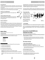
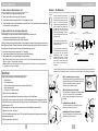
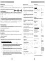
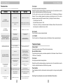
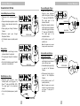
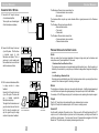
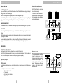
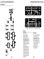
Limited
Warranty
The FISHMAN Pocket Blender is warranted to function for a period of One (1)
Year from the date of purchase. If the unit fails to function properly within the
warranty period, free repair and the option of replacement or refund in the event
that FISHMAN is unable to make repair are FISHMAN’s only obligations. This
warranty does not cover any consequential damages or damage to the unit due
to misuse, accident, or neglect. FISHMAN retains the right to make such
determination on the basis of factory inspection. Products returned to FISHMAN
for repair or replacement must be shipped in accordance with the Return Policy,
as follows. This warranty remains valid only if repairs are performed by
FISHMAN. This warranty gives you specific legal rights and you may also have
other rights which may vary from state to state.
User
Guide
Pocket Blender
Acoustic Instrument Preamp
Return Policy
To return products to FISHMAN TRANSDUCERS, you must follow these steps...
1. Call FISHMAN TRANSDUCERS at 978-988-9199 for a Return Authorization
Number (“RAN”).
2. Enclose a copy of the original Bill of Sale as evidence of the date of purchase,
with the product in its original packaging and a protective carton or mailer.
3. FISHMAN TRANSDUCERS’ technicians will determine whether the item is
covered by warranty or if it instead has been damaged by improper customer
installation or other causes not related to defects in material or workmanship.
4. Warranty repairs or replacements will be sent automatically free of charge.
5. If FISHMAN TRANSDUCERS determines the item is not covered by warranty,
we will notify you of the repair or replacement cost and wait for your authorization
to proceed.
FISHMAN TRANSDUCERS
340-D Fordham Road Wilmington MA 01887 USA
Phone 978-988-9199 • Fax 978-988-0770
www.fishman.com
Rev 2 • 4-11-02 • 009-010-001
®
®
Pocket Blender
Pocket Blender
Thank you for choosing the Fishman Pocket Blender. Our goal is to provide you with acoustic amplification
products that will simply let you sound your best. With our long-standing commitment to quality, you can
feel confident that your Fishman gear will produce great sound and trouble-free performance for years to
come. Please take a few minutes to read this guide and familiarize yourself with the system. Your satisfaction
is very important to us. If you have any questions or comments, please contact us at [email protected] or
by phone at 978-988-9665.
High Frequency Feedback
The microphone's rising response can create a feedback loop with a high frequency driver in your speaker system. This feedback
usually starts above 1.5 kHz, peaks at 4 kHz and subsides at 9 kHz. There are several approaches to minimizing high frequency
feedback:
1. Strategic Positioning: This works best in low to medium volume settings. The simplest solution for this type of feedback is to keep
the microphone out of the path of the loudspeaker.
You can do this by:
a. Avoid standing directly in front of your amp.
b. Send separate mix and transducer signals to your soundman and have only the transducer signal sent to your stage
monitor.
CONTENTS
2. Turn down the treble control on microphone channel.
Introduction ...................................................................... 12
Install pickup/Microphone on the instrument ................... 13
Quick Start ....................................................................... 14
Features ........................................................................... 15
Power Options .................................................................. 16
Front Panel
Microphone Channel ............................................ 16
Transducer Channel ............................................ 17
Master Section ..................................................... 18
Rear Panel ....................................................................... 18
Suggested Input Options ................................................. 10
Suggested Output Options .............................................. 12
Outputs/Effects Loops ..................................................... 13
Trouble Shooting ............................................................. 14
Optional Accessories ....................................................... 15
Specifications ................................................................... 15
Block Diagram ................................................................ 16
Appendix - The Microphone ........................................... 17
3. Reverse phase switches on both channels.
4. Insert an outboard equalizer after the Pocket Blender's output (i.e.):
a. EQ with sweepable frequencies: The Fishman Pro EQ Platinum has sweepable frequencies to let you dial out high
freq. feedback.
b. Parametric EQ: We suggest cutting 5 dB at 4 kHz, with a 1.5 octave bandwidth (Q).
c. Graphic EQ: Cut 3 dB at 1.2 kHz. Gradually increase the amount of cut to -9 dB at 4-5 kHz. Above 5 kHz, gradually
decrease the amount of cut to -3 dB at 10 kHz.
FIG. 1
FIG. 2
-30
-30
-30
-20
-20
-20
-10
-10
-10
dB 0
dB 0
dB 0
-10
-10
-10
-20
-30
-20
-30
20
100
1k
10k 20k
-20
-30
20
100
1k
INTRODUCTION: THE BLENDER SYSTEM
The Fishman Pocket Blender is a compact yet full-featured
2-channel outboard mixer/preamp designed for acoustic
stringed instruments. It is specifically set up for blending a
pickup with an onboard miniature microphone.
1 - Microphone and Pickup (Transducer)
Everyone loves the way a microphone captures the natural
ambience and resonance of an acoustic instrument. But
microphones have a downside; they feedback when you
crank up the volume and tend to get lost in the mix when
there are other amplified instruments onstage. Pickups
deliver a balanced high output signal with low feedback,
but they can sound somewhat dry compared to
microphones.
UNDER-SADDLE PIEZO
TRANSDUCER
MINI-MICROPHONE MOUNTED ON
X-BRACE NEAR SOUNDHOLE
2
19
10k 20k
20
100
1k
10k 20k
Pocket Blender
Pocket Blender
Using other Microphones
The Pocket Blender is also compatible with other manufacturers' mini-electret Microphones. Consult the manufacturer for specific
minimum power requirements, wiring configuration and instrument mounting systems (the Fishman Microphone mounts are dedicated
to the Crown GLM series).
The Pocket Blender allows you to combine the benefits of both pickup and microphone signals to achieve results not
available by simply using one or the other. With this system, a microphone rounds out the dry, direct sound of a pickup
- while the "bite" of a pickup adds focus and definition to the microphone sound.
Dynamic Microphones (such as the SM 58) may be used with the Pocket Blender. You'll need a low to high impedance adapter plugged
into the Ring jack of a stereo "Y" cable. Turn off the 9-Volt Phantom Power (switch is out) for this application.
We recommend (and sell) the Crown GLM-200 mini-microphone for the Pocket Blender. Electret microphones made
by other manufacturer's can be modified for use with the Pocket Blender (contact the manufacturer for specific wiring).
LESS BASS
Positioning the Crown GLM-200 Microphone
It's worth taking the time to experiment with mic placement. Here are some suggestions to help you
get started:
Internally mounted Microphone(flat top guitars)
Start with the Microphone centered in the soundhole, slightly below the top. Position the face of the
Microphone (marked "FRONT") toward the inside of the instrument. Tilting the Microphone as much
as 90° may help reduce boominess.
2 - Stereo Instrument Cable
MORE BASS
Externally mounted Microphone
(violin, bass, cello, arch-top guitar).
Start with the Microphone centered halfway between a bridge foot and F-hole. Position the face of the Microphone (marked front)
towards the instrument. Tilting the Microphone as much as 90° may help reduce boominess. Placing the Microphone directly over an
F- hole will produce a deep, woody tone. However, the Microphone will feedback at the instrument's cavity resonance. This can be
easily remedied by notching out the feedback with an external equalizer (see below). Placing the Microphone over the soundboard will
produce a tight, focused tone with more midrange emphasis but less overall output.
ADDRESSING FEEDBACK
Low Frequency Feedback
All stringed instruments' sound chambers are tuned to resonate at an optimum frequency, in the instrument's lowest octave. Placing a
Microphone directly over the opening of the instrument may result in feedback at this "cavity resonance".
For convenience, we use a TRS
stereo instrument cable to get the
individual microphone and pickup
signals from the instrument into the
Pocket Blender. The Pocket Blender
supplies a 9-Volt bias voltage through
the ring connection that in turn
powers the mini-microphone.
Push in the bass cut switch on the Microphone Channel.
Stereo Jack
Ring
Stereo Plug
Each channel of the Pocket Blender is set up for the particular signal conditioning requirements of microphone and
pickup. Once the pickup/microphone signals are blended, the composite signal can be routed to amplification,
recording gear or signal processing equipment via XLR and 1/4" outputs. An effects loop is also included for each
channel.
INSTALLING A PICKUP / CROWN GLM 200 MICROPHONE
COMBINATION ON YOUR INSTRUMENT
Before you begin using your Pocket Blender, have a repair professional install the appropriate pickup and
microphone combination for your instrument.
Three Common Scenarios:
1. Position the Microphone away from the opening on non-flattop instruments. This works well in low volume settings.
3.
Pickup Signal
to Tip
Zener Diode
between Ring & Sleeve
Sleeve
Note: The Pocket Blender is also compatible with other manufacturers' mini-electret microphones. Consult the manufacturer
for specific minimum power requirements, wiring configuration and instrument mounting systems (the Fishman microphone
mounts are dedicated to the Crown GLM series).
To Minimize Cavity Resonance Feedback:
Turn down the bass control on the Microphone Channel.
Shield to
Sleeve
Tip
3 - The Pocket Blender
Typical Resonant Frequencies:
Guitar; 95-105 Hz
Bass; 65-75 Hz
Violin; 275-300 Hz
Cello; 125-135 Hz
2.
Microphone to Ring
1 - WIRING A PASSIVE PICKUP & MICROPHONE
A passive pickup is any transducer (piezo or magnetic) that works without a battery.
Note: To minimize crosstalk with a passive pickup, use a "2-pair" premium stereo cable (Fishman part # ACC-BLE-15C) with
separate shields for both the pickup and microphone signals.
4. Invert the Phase switches on both Channels. (See Page 6 )
5. Insert an outboard equalizer after the Pocket Blender's output (i.e.):
a. Notch Filter: The Fishman Pro-EQ Platinum has a notch filter for eliminating low freq. feedback.
b. Parametric EQ: We suggest cutting 5 dB at the instrument's cavity resonance (see above) with a .5 octave bandwidth (Q).
c. Graphic EQ: Cut 5 dB at the instrument's cavity resonance (see above) with 1/3 octave cuts on either side of the center
frequency.
18
1.
2.
3.
4.
Connect red microphone wire to ring terminal.
Connect white and shield microphone wires to sleeve.
Connect pickup signal wire to tip and pickup shield to sleeve.
Connect supplied zener diode in place between red wire (ring) and ground (sleeve).
Note that banded side of diode must be closest to red wire.
3
Pocket Blender
Pocket Blender
APPENDIX I - THE MICROPHONE
2 - WIRING TO ACOUSTIC MATRIX NATURAL I & II
1.
2.
3.
4.
Remove shielding cap to expose preamp circuit board.
Connect red microphone wire to ring pad on circuit board.
Connect white and shield microphone wires to "G" pad adjacent to ring pad.
Connect supplied zener diode in place between red wire and sleeve. Note that banded side of the zener diode
must be closest to red microphone wire.
GLM-200
3 - WIRING THE MIC & PICKUP WITH SEPARATE CONNECTORS
The advantages to wiring the microphone and pickup to separate mono connectors are:
a. Microphone is interchangeable with other instruments.
b. Less cross talk between passive pickups and the microphone.
Typically, classical guitarists and double bassists find this arrangement convenient for sharing the microphone with
several different instruments. Classical guitarists can install the microphone without drilling holes in the instrument. In
this configuration, the microphone can also be removed without disturbing the pickup.
1. Connect red microphone wire to tip terminal on a ¼" mono plug.
2. Connect white microphone wire and shield to sleeve terminal the same plug.
3. Solder supplied zener diode in place between red wire and sleeve.
Note: The banded side of the diode must be closest to the red wire. For use with the Pocket Blender, plug the mic into the
RING jack of a stereo "Y" cable (available from Fishman).
Warning: Installation by a qualified repairperson is strongly recommended. Fishman Transducers Inc. will not be responsible
for any damages due to improper installation.
-30
A variety of microphones can be used with
the Pocket Blender. However, the Crown
GLM-200 is our microphone of choice for the
system. It is a mini-electret condenser
microphone with a hyper-cardioid response
pattern. It's high SPL rating (130 dB), small
size and crystal clear "rising" frequency
response make it ideal for close mic'ing
acoustic stringed instruments. We offer the
GLM-200 optimized specifically for use with
the Blender System.
FRONT
-20
-10
dB 0
-10
-20
-30
REAR
100
20
GLM-200
RESPONSE PATTERN
Microphone to Ring
The Pocket Blender provides 9-Volts of
Phantom power to the GLM-200 via the tip
terminal at the input jack.
ACTUAL
SIZE
A small zener diode is included with the
GLM-200 microphone. It is pre-wired to both
the Bass and Violin jack assemblies
(BMA,BP-100-M, V-200-M). It is included
separately with all other kits. It must be
installed for the microphone to be covered
under warranty. The zener diode prevents
static electricity from damaging the
microphone.
Shield to
Sleeve
1k
10k 20k
GLM-200
FREQUENCY RESPONSE CURVE
Pickup Signal
to Tip
Zener Diode
between Ring & Sleeve
Stereo Jack
Tip
Sleeve
Ring
Stereo Plug
Microphone Wiring (Typical)
The GLM-200's small size allows it to be conveniently mounted in or outside the sound chamber of most stringed instruments. The
microphone, with a (TRS) stereo jack included, can be attached to the instrument using one of the following mounting systems:
QUICK START
To get up and running you'll need these components:
• Pocket Blender
• 9-Volt alkaline battery
• Pickup and mini-microphone connected to a stereo jack (See Page 3)
• Stereo instrument cable
• XLR cable or 1/4" instrument cable
1. Install a fresh 9-Volt alkaline battery.
2. Connect the stereo cable between the instrument and the input of the Pocket Blender.
3. Set the Mute, Lo and Hi switches to the out position. Set the phantom power switch on the rear panel to the in
position. Set both channel volume controls fully counter clockwise. Set the Master level to 3:00. Set all the bass
and treble controls to 12:00.
4. Run a cable from one of the outputs on the rear panel of the Pocket Blender to your amp or PA.
5. Adjust the trim controls - See Page 7
6. With the Pocket Blender's Master Level at 3:00, adjust both the microphone and transducer volume controls to
approximately the same level.
7. Set the phase switches - See Page 6
4
GMA - Guitar Microphone Assembly
The Microphone is mounted in the sound hole with a clip that
attaches to the X-brace under the instrument's soundboard.
The jack is run through the instrument's endpin hole.
Soldering and some assembly is required.
BMA - Bass Microphone Assembly
The mount attaches to a bridge foot with an adhesive backed
nylon clip. The jack (pre wired to Tip) mounts between
the A & D strings. Also available with a pre-wired pickup
(BP-100M).
V-200M Pickup and Mini-Mic
The mount is integrated into a Carpenter-style jack that
attaches above the instrument's chin rest.
M-200M Mandolin Pickup and Mini-Mic
The mount is integrated into a Carpenter-style jack that
attaches to the mandolin's lower bout.
17
Pocket Blender
Pocket Blender
1/4"
MUTE OUTPUT
BALANCED
OUTPUT
BLOCK DIAGRAM
3
4
volume
bass
treble
6
7
8
bass
treble
battery
9
low
phase
hi
volume
lo
volume
phase
mute
POCKET BLENDER
GROUND
LIFT
MASTER
VOLUME
1 Located on top
5
2
trim
trim
MICROPHONE
11
12
13
14
16
15
MIX
10
TRANSDUCER
microphone
send
return
transducer
send
return
ground
lift
9V
Made in the USA
STEREO PLUG
(TRS)
HI CUT
LO CUT
TRIM
PHASE
MICROPHONE
INPUT
STAGE
BASS &
TREBLE
CONTROLS
17
1/4"
INPUT
TRIM
AC ADAPTERS
FISHMAN 910-R,
ROLAND PSA SERIES
output
phantom
power
26
BASS &
TREBLE
CONTROLS
TRANSDUCER
INPUT
STAGE
PHASE
TIP
(Transducer)
RING
(Mic)
SLEEVE
effects loop
microphone - ring
transducer - tip
MICROPHONE MICROPHONE
EFFECTS
EFFECTS
RETURN
SEND
TRANSDUCER TRANSDUCER
EFFECTS
EFFECTS
RETURN
SEND
MICROPHONE
VOLUME
TRANSDUCER
VOLUME
input
18
19
20
21
22
24
25
FEATURES
FEATURES
FRONT PANEL
REAR PANEL
1) BATTERY COMPARTMENT
17) 9-VOLT PHANTOM POWER SWITCH
2) MICROPHONE VOLUME
18) 1/4” INPUT JACK (TRS)
3) MICROPHONE BASS CONTROL
19) MICROPHONE EFFECTS SEND
4) MICROPHONE TREBLE CONTROL
20) MICROPHONE EFFECTS RETURN
5) TRANSDUCER VOLUME CONTROL
21) TRANSDUCER EFFECTS SEND
6) TRANSDUCER BASS CONTROL
22) TRANSDUCERS EFFECTS RETURN
7) TRANSDUCER TREBLE CONTROL
23) 1/4” UNBALANCED OUTPUT
8) BATTERY LOW LED
24) GROUND LIFT SWITCH
9) MASTER VOLUME CONTROL
25) XLR BALANCED OUTPUT
10) MICROPHONE TRIM CONTROL
26) AC ADAPTER INPUT
11) MICROPHONE PHASE SWITCH
12) MICROPHONE HI CUT SWITCH
13) MICROPHONE LO CUT SWITCH
14) TRANSDUCER TRIM CONTROL
15) TRANSDUCER PHASE SWITCH
16
23
16) MUTE SWITCH
5
Pocket Blender
Pocket Blender
POWER OPTIONS
OPTIONAL ACCESSORIES
SPECIFICATIONS
9-Volt Battery
Lift the lid on top of the Pocket Blender and insert a fresh 9-Volt alkaline battery. Observe the correct
polarity. Battery life is an estimated 60 hours of continuous use.
• A/C Adapter: Fishman 910-R regulated 9-Volt power
supply.
Input Impedance:
9-Volt AC Adapter Input
Use only a well filtered and regulated 9-Volt AC adapter. We recommend a Fishman Model-910 or
Roland PSA series regulated AC Adapter. Use of an unregulated adapter will not only void the warranty,
but may damage the unit.
Input Jack
Plug in a TRS stereo cable here. The input will accept two separate signals via a stereo instrument cable.
(Tip = Transducer Channel, Ring = Microphone Channel) Engage the Mute switch before you plug into the
input to avoid a loud pop through the speakers. When you plug in here the battery turns on. To save the
battery remember to unplug the input when you're not using the Pocket Blender.
MICROPHONE CHANNEL
Use the Microphone Channel for a mini-electret microphone (switch 9-Volt phantom on rear panel on) or
with a second pickup (9-Volt phantom off).
Volume Control
Normally set the volume for the microphone at around 12:00 (see Trim instructions below).
Bass And Treble
These shelving style tone controls provide basic equalization for the Microphone Channel. Set them at
12:00 for no cut or boost (flat).
Phase Switches
Prevent feedback and match up the pickup and microphone signals for a stronger amplified sound.
How to kill feedback in the Microphone Channel:
•
•
Adjust the Master volume level to 3:00 and turn the Transducer volume off (7:00).
Adjust the Microphone Channel volume to just below the threshold of feedback. Play your instrument and
toggle the Microphone Channel phase switch. Leave the switch where it feeds-back the least.
How to get the pickup in phase with the microphone:
•
•
After you perform the above step, raise the Transducer Channel volume until it is about the same level as
the Microphone. Play a sustained note or chord on your instrument and toggle the Transducer Channel
Phase switch. Leave the switch in the position that sounds strongest and feeds-back the least.
Once the pickup and Microphone are in Phase, make note of the relative position of the two switches.
They will be either in the same position, or one in and one out. To keep pickup/mic in phase, push both
switches anytime you adjust the overall polarity.
• Crown GLM-200 mini-mic: Ships without jack; ready
to be wired to the jack of your choice. Soldering and
assembly required.
Transducer:
Microphone without phantom power:
10 MΩ
1.0 MΩ
Microphone with 9-Volt phantom power: 10 KΩ
Phantom Power:
9-Volts, .5 mA
Nominal Input Level:
-20 dBV
• Internal Mic Mount: Allows you to mount the Crown
GLM-200 mini-mic to the X-brace of your guitar.
Input Overload:
(20Hz-20kHz)
-8 dBV
• Guitar Mic Assembly: Mounts to the X-brace of your
guitar. Includes a mini-mic, internal mic mount and
stereo endpin jack. Soldering and assembly
required.
Output Type:
• Bass Mic Assembly: Mounts to the bridge foot of an
acoustic bass. Includes pre-wired mini-mic, mic
mount and a stereo bass jack.
• Switchjack Stereo Endpin Jack with Tip, Ring,
Sleeve and Switch terminals
Electronically balanced XLR and unbalanced 1/4" Jack
Output Impedance:
XLR:
220 Ω
1/4” JACK:
1 KΩ
Nominal Output Level:
-11 dBV
Output Overload:
14 dBV
(600 Ohm load)
Effects Loop Nominal Levels:
Transducer channel:
Microphone channel:
-3.5 dBV
-3.0 dBV
Effects Loop Send Impedance:
1 KΩ
Return Impedance:
23 KΩ
Bass Control Range:
Treble Control Range:
± 8 dB shelving
± 13 dB shelving
Front Panel Trim Gain Range:
16 dB
• V-200M: Violin pickup and mini-mic pre-wired to a
Carpenter-style output jack.
Overall THD:
.07% @ 1 kHz,
-14 dBV input
Overall Dynamic Range:
110 dB
• M-200M Mandolin pickup and mini-mic pre-wired to
a Carpenter style output jack.
Signal to Noise Ratio:
• Mic Stand Adapter: Allows you to mount the Pocket
Blender on any Microphone stand.
87 dB (A-weighted,
referred to nominal
- 20 dBV input)
Dual Power Supply:
9-Volt regulated, or
single 9-Volt battery
(Estimated 60 hours
of continuous use)
Dimensions:
6.75" x 2" x 3"
Weight:
1 lb 2 oz
• Stereo Bass Jack: Mounts on the A and D strings
between bridge and tailpiece.
• Transducers: We make a full line of quality
Transducers for many types of acoustic stringed
instruments.
• BP-100M: Bass pickup and mini-mic pre-wired to
stereo bass jack.
• 15' Stereo Cable
• 15' Premium Stereo Cable
• Stereo "Y" Cable: 1/4" stereo male to (2) 1/4" mono
female.
All specifications subject to change without notice
6
15
Pocket Blender
Pocket Blender
TROUBLESHOOTING
Trim Control
(see Joe for new troubleshooting tips)
Set as high as possible without hearing distortion.
Start with the control fully clockwise and play your loudest note or chord. If you hear distortion, lower the
trim with a small slotted screwdriver until the distortion goes away.
The Trim control can also be used to set the baseline levels for the Microphone and Transducer
Channels. If there is a disparity between the microphone and pickup levels, use the Trim control to
attenuate one channel (usually the Transducer Channel). Try setting the Trim controls this way ...
1. Set the Output Level to 3:00.
2. Set both Channel volumes to 12:00.
3. Play a note or chord on your instrument and lower the Transducer Channel Trim control until both
levels are equal, or are balanced to suit your taste.
SYMPTOM
TYPICAL CAUSE
SOLUTION
Symptom
Distorted or no mic signal with active pickup.......
SWITCH
SET MUTE SWITCH TO OUT POSITION
NO signal with battery power.......(delete mixMUTE
return
as INa cause)
No signal with
AC
power....(delete
mix
return
as
a
cause)
NO SIGNAL
WITH BATTERY
Microphone
ChannelPOWER
dead with mini electret Microphone connected to INPUT jack..... (fix phantom power
COMPARTMENT
REMOVE BATTERY AND RE-TENSION TERMIorientation, delete AUX/mic in override)LOOSE BATTERY
TERMINALS
NALS BY PULLING THEM UP WITH YOUR FINGER
Mic is dead and pickup appears in Microphone Channel.......
Piezo/magnetic pickup dead or low level in mic Channel ....
Noise or distortion
from either Channel......
NO SIGNAL
MUTE SWITCH IN
SET MUTE SWITCH TO OUT POSITION
WITH ACsolution
POWER
(fix low battery
Distortion from extremely "hot" signals.......(fix?)
PHANTOM POWER IS OFF
TURN PHANTOM POWER ON
Hum.....
( SWITCH IS OUT )
( SWITCH IS IN )
MICROPHONE
CHANNEL
DEAD
Piezo
high frequency
loss.....(delete)
WITH MINI-MICROPHONE
CONNECTED TO INPUT JACK
MICROPHONE IS DEAD AND PICKUP
APPEARS IN MICROPHONE CHANNEL
DEVICE APPEARING AT THE
MICROPHONE EFFECTS RETURN
IS BREAKING THE SIGNAL PATH
REMOVE PLUG FROM THE
MICROPHONE EFFECTS RETURN
MICROPHONE AND PICKUP ARE WIRED TO STEREO
OUTPUT JACK BACKWARDS
( MICROPHONE TO TIP AND PICKUP TO RING )
WIRE PICKUP TO TIP AND MICROPHONE TO
RING OF STEREO OUTPUT JACK
LOW BATTERY
WHEN LOW BATTERY LED STAYS ON
WITH INPUT JACK PLUGGED IN,
IT IS TIME TO CHANGE THE BATTERY
TRIM CONTROL(S) SET TOO HIGH
LOWER TRIM CONTROL(S)
UNTIL DISTORTION DISAPPEARS
MECHANICAL NOISE FROM INSTRUMENT
LISTEN TO INSTRUMENT ACOUSTICALLY
TO ISOLATE NOISE
MECHANICAL NOISE FROM
INSTRUMENT CABLE
TIGHTEN ALL PLUG HARDWARE
INPUT CLIPS WITH TRIM CONTROL
ALL THE WAY DOWN
CONSULT FISHMAN TECH SUPPORT LINE
AT 978-988-9665
AN UNREGULATED POWER SUPPLY WILL CAUSE THE
POCKET BLENDER TO HUM UNDER AC POWER
USE ONLY FISHMAN 910-R
OR ROLAND PSA SERIES AC ADAPTERS
POORLY SHIELDED OR
UNSHIELDED CABLE
USE ONLY QUALITY FULLY SHIELDED
INSTRUMENT CABLES
INSTRUMENT CABLE IS TOO LONG
USE ONLY 15’ OR SHORTER INSTRUMENT
CABLES WITH PASSIVE PICKUP
Hi Cut Switch
Push in this switch to reduce microphone feedback.
Lo Cut Switch
Push in this switch to roll off excessive boominess in the Microphone Channel, especially for guitar.
TRANSDUCER CHANNEL
Volume Control
Normally set the volume at around 12:00 (see Trim instructions below).
NOISE OR DISTORTION
FROM EITHER CHANNEL
DISTORTION FROM EXTREMELY
‘HOT’ SIGNALS SUCH AS
EXTERNAL PICKUP
HUM
HIGH FREQUENCY LOSS WITH
PASSIVE PIEZO
14
Bass and Treble Controls
These shelving style tone controls provide basic equalization for the Transducer Channel. Set them at
12:00 for no cut or boost (flat).
Trim Control
Set as high as possible without hearing distortion.
Start with the control fully clockwise and play your loudest note or chord. If you hear distortion, lower the
trim with a small slotted screwdriver until the distortion goes away.
Phase Switches
Prevent feedback and match up the pickup and microphone signals for a stronger sounding amplified
signal.
Refer to Page 6 for more information on how to use the Pocket Blender's Phase switches.
7
Pocket Blender
Pocket Blender
MASTER SECTION
USING MULTIPLE OUTPUTS
Low Battery Indicator
All the Pocket Blender's outputs can
be used simultaneously.
This offers a basic combination of
signal routing and interfacing options
to accommodate most performance
and recording situations.
If you use a battery to power the Pocket Blender, the LED will flash briefly when you plug into the inputtelling you that the unit is powering up.
When the red LED lights with no signal present it is time to change the battery.
If the low battery light comes on while you're playing don't worry, you'll have enough power to get through
a gig. Just be sure to change the battery before the next time you use the preamp.
STAGE AMP
input
effects loop
microphone - ring
transducer - tip
Master Volume Control
STAGE AMP
transducer
send
return
phantom
power
For the cleanest sound, set the master volume as high as you can without distorting your amp or mixer.
AC ADAPTERS
FISHMAN 910-R,
ROLAND PSA SERIES
output
microphone
send
return
ground
lift
9V
Made in the USA
Mute Switch
DIRECT
BOX
Mutes all signals at the output section, so you can take breaks without changing any of your volume
settings.
With the mute engaged you can also silently disconnect the cable from your instrument without a loud
pop through the speakers.
The mute switch is also useful with an electronic tuner. Plug the tuner into the transducer send and
engage the mute switch. You can now tune onstage without being heard through the speakers.
PICKUP SIGNAL ONLY
SENT TO STAGE MONITOR
POWER AMP AND SPEAKERS
MIXER
REAR PANEL
9-Volt Phantom Power Switch
Push the switch in for 9 volts bias voltage to the ring contact of the Input jack.
Push the 9-Volt phantom power switch in when you use a mini-electret microphone. Push the switch out
if you will use the Microphone Channel for a second pickup (piezo or magnetic)
Input jack (see Page 6)
Effects Loops
The microphone effects loop lets you insert outboard effects or signal processors into the Microphone
Channel.
The microphone channel send comes after the:
• Bass and treble controls
• Trim control
• HI cut and LO cut switches
• Phase switch
8
EFFECTS LOOPS
The Pocket Blender has two effects
loops for microphone and for
transducer signals. The sends can be
used as additional outputs. The
returns can be used as alternate
inputs. The transducer effects send
makes a perfect output signal for
electronic tuners.
input
effects loop
microphone - ring
transducer - tip
AC ADAPTERS
FISHMAN 910-R,
ROLAND PSA SERIES
output
microphone
send
return
transducer
send
return
phantom
power
ground
lift
9V
Made in the USA
DIGITAL REVERB
13
Pocket Blender
Pocket Blender
The Microphone Channel return comes before the:
• Volume and master volume controls
• Mute Switch
The transducer effects loop lets you insert outboard effects or signal processors into the Transducer
Channel.
The Transducer Channel send comes after the:
• Bass and treble controls
• Trim control
• Phase switch
The Transducer Channel return comes before:
• Volume and master volume controls
• Phase and mute switches
SUGGESTED OUTPUT OPTIONS
1. Connect the 1/4" output to the input
of an instrument amplifier.
The amp will see a blended signal
of both microphone and pickup.
2. Connect the XLR output to the input
of your PA system. The PA will see
a blended signal of both
Microphone and pickup. This is a
great way to control exactly what
the soundman has to work with and
what the audience will hear.
3. XLR to mains and transducer effects
to stage monitors to reduce
feedback.
Connect the XLR output to the input
of your PA system. The house will
see a blended signal-both
Microphone and pickup.
The signal from the transducer send
goes into a direct box and then into
the PA. Have the soundman put
only this signal through the stage
monitors to help reduce feedback.
input
microphone - ring
transducer - tip
effects loop
AC ADAPTERS
FISHMAN 910-R,
ROLAND PSA SERIES
output
microphone
send
return
transducer
send
return
phantom
power
ground
lift
9V
Made in the USA
input
microphone - ring
transducer - tip
effects loop
AC ADAPTERS
FISHMAN 910-R,
ROLAND PSA SERIES
output
microphone
send
return
transducer
send
return
phantom
power
PATCHING OPTIONS WITH THE EFFECTS LOOPS
ground
lift
9V
Made in the USA
Sends
input
microphone - ring
transducer - tip
effects loop
AC ADAPTERS
FISHMAN 910-R,
ROLAND PSA SERIES
output
microphone
send
return
When you need a fixed level signal (regardless of changes in stage level) use the transducer and
microphone sends. Typical applications for the sends:
• Transducer Send to an Electronic Tuner
The transducer send provides a strong and steady signal for electronic tuners. Since the send is not
affected by the mute switch, you may tune your instrument onstage without being heard through the
speakers.
• Live Recording or Broadcast Feed
Since the sends are not affected by any of the front panel volume controls, you can plug them into an
external DI for a fixed level signal for recording or radio gear.
transducer
send
return
phantom
power
ground
lift
Returns
9V
Made in the USA
The microphone or transducer returns can be used as alternate inputs. A buffered signal appearing at
one of the Returns will replace the signal appearing at the respective input of the Pocket Blender.
For example, a CD or MD player can plug into the microphone return, replacing the microphone signal.
Outputs
Plug the 1/4" output into an instrument amplifier or an unbalanced input on a mixer.
Plug the XLR output into the balanced input of a PA mixer or recording console.
TRANSDUCER SIGNAL ONLY
SENT TO STAGE MONITOR
BLENDED SIGNAL
SENT TO MAINS
Ground Lift
Use this switch to eliminate AC ground loop hum. When you use the XLR output together with the 1/4"
output or one of the effects loops and you hear hum from the speakers, push the ground lift switch in
and the hum should go away. If you have more than one AC powered device plugged into the Pocket
Blender, the "lift" position may not completely eliminate ground loop hum.
12
9
Pocket Blender
Pocket Blender
Piezo and Magnetic Pickup
SUGGESTED INPUT OPTIONS
Internal Microphone and Pickup
• Pickup goes to tip, microphone goes to
ring.
• Pickup and microphone signals are routed
through a stereo instrument cable to the
input jack.
• Pickup signal goes through Transducer
Channel.
• Microphone signal goes through
Microphone Channel.
• 9-Volt phantom power on (switch pushed
in).
low
volume
bass
phase
treble
hi
volume
lo
bass
treble
battery
phase
volume
mute
POCKET BLENDER
trim
trim
input
effects loop
microphone - ring
transducer - tip
AC ADAPTERS
FISHMAN 910-R,
ROLAND PSA SERIES
output
microphone
send
return
transducer
send
return
phantom
power
ground
lift
9V
Made in the USA
STEREO CABLE
volume
• Single pickup is sent through a mono
instrument cable to the input jack.
• The signal goes through the transducer
channel.
• Turn the 9-Volt phantom power off (switch
pushed out) to save battery life.
Mini-Microphone Alone
bass
phase
volume
lo
bass
treble
battery
phase
microphone - ring
transducer - tip
effects loop
AC ADAPTERS
FISHMAN 910-R,
ROLAND PSA SERIES
output
microphone
send
return
transducer
send
return
phantom
power
ground
lift
9V
Made in the USA
STEREO Y CABLE
MONO CABLE
MONO CABLE
volume
mute
POCKET BLENDER
trim
trim
input
effects loop
microphone - ring
transducer - tip
Under-saddle and Surfacemount Piezo Pickups
AC ADAPTERS
FISHMAN 910-R,
ROLAND PSA SERIES
output
microphone
send
return
transducer
send
return
phantom
power
ground
lift
9V
Made in the USA
MONO CABLE
low
volume
bass
phase
• Microphone goes through a mono
instrument cable to the ring jack of a
Stereo "Y" cable (p/n ACC-BLE- CBY).
The signal goes to the microphone
channel.
• Turn the 9-Volt phantom power on (switch
is in).
treble
hi
input
Note: Both signals may be routed
through a stereo instrument cable.
low
Pickup Alone
• Signal from piezo is routed
through a mono instrument
cable to the tip jack of a Stereo
"Y" cable (p/n ACC-BLE-CBY).
This signal goes to the
transducer channel.
• Signal from magnetic pickup is
sent through a mono instrument
cable to the ring jack of a Stereo
"Y" cable (p/n ACC-BLE-CBY).
This signal goes to the
microphone channel
• 9-Volt phantom power is off
(switch is out).
treble
hi
volume
lo
bass
treble
battery
phase
volume
mute
POCKET BLENDER
trim
trim
input
effects loop
microphone - ring
transducer - tip
AC ADAPTERS
FISHMAN 910-R,
ROLAND PSA SERIES
output
microphone
send
return
microphone - ring
transducer - tip
effects loop
ground
lift
9V
Made in the USA
STEREO Y CABLE
transducer
send
return
phantom
power
ground
lift
9V
Made in the USA
STEREO CABLE
TIP
RING
MONO CABLE
10
AC ADAPTERS
FISHMAN 910-R,
ROLAND PSA SERIES
output
microphone
send
return
Note: Both signals may be routed
through two mono instrument cables
and a stereo "Y" cable (p/n ACCBLE-CBY).
transducer
send
return
phantom
power
• Signals from both pickups are
sent through a stereo instrument
cable to the input jack.
• Under-saddle pickup signal (tip)
is routed to the Transducer
Channel.
• Surface-mount pickup (ring) is
routed to the Microphone
Channel.
• 9-Volt phantom power is off
(switch pushed out).
input
11
Pocket Blender
Pocket Blender
The Microphone Channel return comes before the:
• Volume and master volume controls
• Mute Switch
The transducer effects loop lets you insert outboard effects or signal processors into the Transducer
Channel.
The Transducer Channel send comes after the:
• Bass and treble controls
• Trim control
• Phase switch
The Transducer Channel return comes before:
• Volume and master volume controls
• Phase and mute switches
SUGGESTED OUTPUT OPTIONS
1. Connect the 1/4" output to the input
of an instrument amplifier.
The amp will see a blended signal
of both microphone and pickup.
2. Connect the XLR output to the input
of your PA system. The PA will see
a blended signal of both
Microphone and pickup. This is a
great way to control exactly what
the soundman has to work with and
what the audience will hear.
3. XLR to mains and transducer effects
to stage monitors to reduce
feedback.
Connect the XLR output to the input
of your PA system. The house will
see a blended signal-both
Microphone and pickup.
The signal from the transducer send
goes into a direct box and then into
the PA. Have the soundman put
only this signal through the stage
monitors to help reduce feedback.
input
microphone - ring
transducer - tip
effects loop
AC ADAPTERS
FISHMAN 910-R,
ROLAND PSA SERIES
output
microphone
send
return
transducer
send
return
phantom
power
ground
lift
9V
Made in the USA
input
microphone - ring
transducer - tip
effects loop
AC ADAPTERS
FISHMAN 910-R,
ROLAND PSA SERIES
output
microphone
send
return
transducer
send
return
phantom
power
PATCHING OPTIONS WITH THE EFFECTS LOOPS
ground
lift
9V
Made in the USA
Sends
input
microphone - ring
transducer - tip
effects loop
AC ADAPTERS
FISHMAN 910-R,
ROLAND PSA SERIES
output
microphone
send
return
When you need a fixed level signal (regardless of changes in stage level) use the transducer and
microphone sends. Typical applications for the sends:
• Transducer Send to an Electronic Tuner
The transducer send provides a strong and steady signal for electronic tuners. Since the send is not
affected by the mute switch, you may tune your instrument onstage without being heard through the
speakers.
• Live Recording or Broadcast Feed
Since the sends are not affected by any of the front panel volume controls, you can plug them into an
external DI for a fixed level signal for recording or radio gear.
transducer
send
return
phantom
power
ground
lift
Returns
9V
Made in the USA
The microphone or transducer returns can be used as alternate inputs. A buffered signal appearing at
one of the Returns will replace the signal appearing at the respective input of the Pocket Blender.
For example, a CD or MD player can plug into the microphone return, replacing the microphone signal.
Outputs
Plug the 1/4" output into an instrument amplifier or an unbalanced input on a mixer.
Plug the XLR output into the balanced input of a PA mixer or recording console.
TRANSDUCER SIGNAL ONLY
SENT TO STAGE MONITOR
BLENDED SIGNAL
SENT TO MAINS
Ground Lift
Use this switch to eliminate AC ground loop hum. When you use the XLR output together with the 1/4"
output or one of the effects loops and you hear hum from the speakers, push the ground lift switch in
and the hum should go away. If you have more than one AC powered device plugged into the Pocket
Blender, the "lift" position may not completely eliminate ground loop hum.
12
9
Pocket Blender
Pocket Blender
MASTER SECTION
USING MULTIPLE OUTPUTS
Low Battery Indicator
All the Pocket Blender's outputs can
be used simultaneously.
This offers a basic combination of
signal routing and interfacing options
to accommodate most performance
and recording situations.
If you use a battery to power the Pocket Blender, the LED will flash briefly when you plug into the inputtelling you that the unit is powering up.
When the red LED lights with no signal present it is time to change the battery.
If the low battery light comes on while you're playing don't worry, you'll have enough power to get through
a gig. Just be sure to change the battery before the next time you use the preamp.
STAGE AMP
input
effects loop
microphone - ring
transducer - tip
Master Volume Control
STAGE AMP
transducer
send
return
phantom
power
For the cleanest sound, set the master volume as high as you can without distorting your amp or mixer.
AC ADAPTERS
FISHMAN 910-R,
ROLAND PSA SERIES
output
microphone
send
return
ground
lift
9V
Made in the USA
Mute Switch
DIRECT
BOX
Mutes all signals at the output section, so you can take breaks without changing any of your volume
settings.
With the mute engaged you can also silently disconnect the cable from your instrument without a loud
pop through the speakers.
The mute switch is also useful with an electronic tuner. Plug the tuner into the transducer send and
engage the mute switch. You can now tune onstage without being heard through the speakers.
PICKUP SIGNAL ONLY
SENT TO STAGE MONITOR
POWER AMP AND SPEAKERS
MIXER
REAR PANEL
9-Volt Phantom Power Switch
Push the switch in for 9 volts bias voltage to the ring contact of the Input jack.
Push the 9-Volt phantom power switch in when you use a mini-electret microphone. Push the switch out
if you will use the Microphone Channel for a second pickup (piezo or magnetic)
Input jack (see Page 6)
Effects Loops
The microphone effects loop lets you insert outboard effects or signal processors into the Microphone
Channel.
The microphone channel send comes after the:
• Bass and treble controls
• Trim control
• HI cut and LO cut switches
• Phase switch
8
EFFECTS LOOPS
The Pocket Blender has two effects
loops for microphone and for
transducer signals. The sends can be
used as additional outputs. The
returns can be used as alternate
inputs. The transducer effects send
makes a perfect output signal for
electronic tuners.
input
effects loop
microphone - ring
transducer - tip
AC ADAPTERS
FISHMAN 910-R,
ROLAND PSA SERIES
output
microphone
send
return
transducer
send
return
phantom
power
ground
lift
9V
Made in the USA
DIGITAL REVERB
13
Pocket Blender
Pocket Blender
TROUBLESHOOTING
Trim Control
(see Joe for new troubleshooting tips)
Set as high as possible without hearing distortion.
Start with the control fully clockwise and play your loudest note or chord. If you hear distortion, lower the
trim with a small slotted screwdriver until the distortion goes away.
The Trim control can also be used to set the baseline levels for the Microphone and Transducer
Channels. If there is a disparity between the microphone and pickup levels, use the Trim control to
attenuate one channel (usually the Transducer Channel). Try setting the Trim controls this way ...
1. Set the Output Level to 3:00.
2. Set both Channel volumes to 12:00.
3. Play a note or chord on your instrument and lower the Transducer Channel Trim control until both
levels are equal, or are balanced to suit your taste.
SYMPTOM
TYPICAL CAUSE
SOLUTION
Symptom
Distorted or no mic signal with active pickup.......
SWITCH
SET MUTE SWITCH TO OUT POSITION
NO signal with battery power.......(delete mixMUTE
return
as INa cause)
No signal with
AC
power....(delete
mix
return
as
a
cause)
NO SIGNAL
WITH BATTERY
Microphone
ChannelPOWER
dead with mini electret Microphone connected to INPUT jack..... (fix phantom power
COMPARTMENT
REMOVE BATTERY AND RE-TENSION TERMIorientation, delete AUX/mic in override)LOOSE BATTERY
TERMINALS
NALS BY PULLING THEM UP WITH YOUR FINGER
Mic is dead and pickup appears in Microphone Channel.......
Piezo/magnetic pickup dead or low level in mic Channel ....
Noise or distortion
from either Channel......
NO SIGNAL
MUTE SWITCH IN
SET MUTE SWITCH TO OUT POSITION
WITH ACsolution
POWER
(fix low battery
Distortion from extremely "hot" signals.......(fix?)
PHANTOM POWER IS OFF
TURN PHANTOM POWER ON
Hum.....
( SWITCH IS OUT )
( SWITCH IS IN )
MICROPHONE
CHANNEL
DEAD
Piezo
high frequency
loss.....(delete)
WITH MINI-MICROPHONE
CONNECTED TO INPUT JACK
MICROPHONE IS DEAD AND PICKUP
APPEARS IN MICROPHONE CHANNEL
DEVICE APPEARING AT THE
MICROPHONE EFFECTS RETURN
IS BREAKING THE SIGNAL PATH
REMOVE PLUG FROM THE
MICROPHONE EFFECTS RETURN
MICROPHONE AND PICKUP ARE WIRED TO STEREO
OUTPUT JACK BACKWARDS
( MICROPHONE TO TIP AND PICKUP TO RING )
WIRE PICKUP TO TIP AND MICROPHONE TO
RING OF STEREO OUTPUT JACK
LOW BATTERY
WHEN LOW BATTERY LED STAYS ON
WITH INPUT JACK PLUGGED IN,
IT IS TIME TO CHANGE THE BATTERY
TRIM CONTROL(S) SET TOO HIGH
LOWER TRIM CONTROL(S)
UNTIL DISTORTION DISAPPEARS
MECHANICAL NOISE FROM INSTRUMENT
LISTEN TO INSTRUMENT ACOUSTICALLY
TO ISOLATE NOISE
MECHANICAL NOISE FROM
INSTRUMENT CABLE
TIGHTEN ALL PLUG HARDWARE
INPUT CLIPS WITH TRIM CONTROL
ALL THE WAY DOWN
CONSULT FISHMAN TECH SUPPORT LINE
AT 978-988-9665
AN UNREGULATED POWER SUPPLY WILL CAUSE THE
POCKET BLENDER TO HUM UNDER AC POWER
USE ONLY FISHMAN 910-R
OR ROLAND PSA SERIES AC ADAPTERS
POORLY SHIELDED OR
UNSHIELDED CABLE
USE ONLY QUALITY FULLY SHIELDED
INSTRUMENT CABLES
INSTRUMENT CABLE IS TOO LONG
USE ONLY 15’ OR SHORTER INSTRUMENT
CABLES WITH PASSIVE PICKUP
Hi Cut Switch
Push in this switch to reduce microphone feedback.
Lo Cut Switch
Push in this switch to roll off excessive boominess in the Microphone Channel, especially for guitar.
TRANSDUCER CHANNEL
Volume Control
Normally set the volume at around 12:00 (see Trim instructions below).
NOISE OR DISTORTION
FROM EITHER CHANNEL
DISTORTION FROM EXTREMELY
‘HOT’ SIGNALS SUCH AS
EXTERNAL PICKUP
HUM
HIGH FREQUENCY LOSS WITH
PASSIVE PIEZO
14
Bass and Treble Controls
These shelving style tone controls provide basic equalization for the Transducer Channel. Set them at
12:00 for no cut or boost (flat).
Trim Control
Set as high as possible without hearing distortion.
Start with the control fully clockwise and play your loudest note or chord. If you hear distortion, lower the
trim with a small slotted screwdriver until the distortion goes away.
Phase Switches
Prevent feedback and match up the pickup and microphone signals for a stronger sounding amplified
signal.
Refer to Page 6 for more information on how to use the Pocket Blender's Phase switches.
7
Pocket Blender
Pocket Blender
POWER OPTIONS
OPTIONAL ACCESSORIES
SPECIFICATIONS
9-Volt Battery
Lift the lid on top of the Pocket Blender and insert a fresh 9-Volt alkaline battery. Observe the correct
polarity. Battery life is an estimated 60 hours of continuous use.
• A/C Adapter: Fishman 910-R regulated 9-Volt power
supply.
Input Impedance:
9-Volt AC Adapter Input
Use only a well filtered and regulated 9-Volt AC adapter. We recommend a Fishman Model-910 or
Roland PSA series regulated AC Adapter. Use of an unregulated adapter will not only void the warranty,
but may damage the unit.
Input Jack
Plug in a TRS stereo cable here. The input will accept two separate signals via a stereo instrument cable.
(Tip = Transducer Channel, Ring = Microphone Channel) Engage the Mute switch before you plug into the
input to avoid a loud pop through the speakers. When you plug in here the battery turns on. To save the
battery remember to unplug the input when you're not using the Pocket Blender.
MICROPHONE CHANNEL
Use the Microphone Channel for a mini-electret microphone (switch 9-Volt phantom on rear panel on) or
with a second pickup (9-Volt phantom off).
Volume Control
Normally set the volume for the microphone at around 12:00 (see Trim instructions below).
Bass And Treble
These shelving style tone controls provide basic equalization for the Microphone Channel. Set them at
12:00 for no cut or boost (flat).
Phase Switches
Prevent feedback and match up the pickup and microphone signals for a stronger amplified sound.
How to kill feedback in the Microphone Channel:
•
•
Adjust the Master volume level to 3:00 and turn the Transducer volume off (7:00).
Adjust the Microphone Channel volume to just below the threshold of feedback. Play your instrument and
toggle the Microphone Channel phase switch. Leave the switch where it feeds-back the least.
How to get the pickup in phase with the microphone:
•
•
After you perform the above step, raise the Transducer Channel volume until it is about the same level as
the Microphone. Play a sustained note or chord on your instrument and toggle the Transducer Channel
Phase switch. Leave the switch in the position that sounds strongest and feeds-back the least.
Once the pickup and Microphone are in Phase, make note of the relative position of the two switches.
They will be either in the same position, or one in and one out. To keep pickup/mic in phase, push both
switches anytime you adjust the overall polarity.
• Crown GLM-200 mini-mic: Ships without jack; ready
to be wired to the jack of your choice. Soldering and
assembly required.
Transducer:
Microphone without phantom power:
10 MΩ
1.0 MΩ
Microphone with 9-Volt phantom power: 10 KΩ
Phantom Power:
9-Volts, .5 mA
Nominal Input Level:
-20 dBV
• Internal Mic Mount: Allows you to mount the Crown
GLM-200 mini-mic to the X-brace of your guitar.
Input Overload:
(20Hz-20kHz)
-8 dBV
• Guitar Mic Assembly: Mounts to the X-brace of your
guitar. Includes a mini-mic, internal mic mount and
stereo endpin jack. Soldering and assembly
required.
Output Type:
• Bass Mic Assembly: Mounts to the bridge foot of an
acoustic bass. Includes pre-wired mini-mic, mic
mount and a stereo bass jack.
• Switchjack Stereo Endpin Jack with Tip, Ring,
Sleeve and Switch terminals
Electronically balanced XLR and unbalanced 1/4" Jack
Output Impedance:
XLR:
220 Ω
1/4” JACK:
1 KΩ
Nominal Output Level:
-11 dBV
Output Overload:
14 dBV
(600 Ohm load)
Effects Loop Nominal Levels:
Transducer channel:
Microphone channel:
-3.5 dBV
-3.0 dBV
Effects Loop Send Impedance:
1 KΩ
Return Impedance:
23 KΩ
Bass Control Range:
Treble Control Range:
± 8 dB shelving
± 13 dB shelving
Front Panel Trim Gain Range:
16 dB
• V-200M: Violin pickup and mini-mic pre-wired to a
Carpenter-style output jack.
Overall THD:
.07% @ 1 kHz,
-14 dBV input
Overall Dynamic Range:
110 dB
• M-200M Mandolin pickup and mini-mic pre-wired to
a Carpenter style output jack.
Signal to Noise Ratio:
• Mic Stand Adapter: Allows you to mount the Pocket
Blender on any Microphone stand.
87 dB (A-weighted,
referred to nominal
- 20 dBV input)
Dual Power Supply:
9-Volt regulated, or
single 9-Volt battery
(Estimated 60 hours
of continuous use)
Dimensions:
6.75" x 2" x 3"
Weight:
1 lb 2 oz
• Stereo Bass Jack: Mounts on the A and D strings
between bridge and tailpiece.
• Transducers: We make a full line of quality
Transducers for many types of acoustic stringed
instruments.
• BP-100M: Bass pickup and mini-mic pre-wired to
stereo bass jack.
• 15' Stereo Cable
• 15' Premium Stereo Cable
• Stereo "Y" Cable: 1/4" stereo male to (2) 1/4" mono
female.
All specifications subject to change without notice
6
15
Pocket Blender
Pocket Blender
1/4"
MUTE OUTPUT
BALANCED
OUTPUT
BLOCK DIAGRAM
3
4
volume
bass
treble
6
7
8
bass
treble
battery
9
low
phase
hi
volume
lo
volume
phase
mute
POCKET BLENDER
GROUND
LIFT
MASTER
VOLUME
1 Located on top
5
2
trim
trim
MICROPHONE
11
12
13
14
16
15
MIX
10
TRANSDUCER
microphone
send
return
transducer
send
return
ground
lift
9V
Made in the USA
STEREO PLUG
(TRS)
HI CUT
LO CUT
TRIM
PHASE
MICROPHONE
INPUT
STAGE
BASS &
TREBLE
CONTROLS
17
1/4"
INPUT
TRIM
AC ADAPTERS
FISHMAN 910-R,
ROLAND PSA SERIES
output
phantom
power
26
BASS &
TREBLE
CONTROLS
TRANSDUCER
INPUT
STAGE
PHASE
TIP
(Transducer)
RING
(Mic)
SLEEVE
effects loop
microphone - ring
transducer - tip
MICROPHONE MICROPHONE
EFFECTS
EFFECTS
RETURN
SEND
TRANSDUCER TRANSDUCER
EFFECTS
EFFECTS
RETURN
SEND
MICROPHONE
VOLUME
TRANSDUCER
VOLUME
input
18
19
20
21
22
24
25
FEATURES
FEATURES
FRONT PANEL
REAR PANEL
1) BATTERY COMPARTMENT
17) 9-VOLT PHANTOM POWER SWITCH
2) MICROPHONE VOLUME
18) 1/4” INPUT JACK (TRS)
3) MICROPHONE BASS CONTROL
19) MICROPHONE EFFECTS SEND
4) MICROPHONE TREBLE CONTROL
20) MICROPHONE EFFECTS RETURN
5) TRANSDUCER VOLUME CONTROL
21) TRANSDUCER EFFECTS SEND
6) TRANSDUCER BASS CONTROL
22) TRANSDUCERS EFFECTS RETURN
7) TRANSDUCER TREBLE CONTROL
23) 1/4” UNBALANCED OUTPUT
8) BATTERY LOW LED
24) GROUND LIFT SWITCH
9) MASTER VOLUME CONTROL
25) XLR BALANCED OUTPUT
10) MICROPHONE TRIM CONTROL
26) AC ADAPTER INPUT
11) MICROPHONE PHASE SWITCH
12) MICROPHONE HI CUT SWITCH
13) MICROPHONE LO CUT SWITCH
14) TRANSDUCER TRIM CONTROL
15) TRANSDUCER PHASE SWITCH
16
23
16) MUTE SWITCH
5
Pocket Blender
Pocket Blender
APPENDIX I - THE MICROPHONE
2 - WIRING TO ACOUSTIC MATRIX NATURAL I & II
1.
2.
3.
4.
Remove shielding cap to expose preamp circuit board.
Connect red microphone wire to ring pad on circuit board.
Connect white and shield microphone wires to "G" pad adjacent to ring pad.
Connect supplied zener diode in place between red wire and sleeve. Note that banded side of the zener diode
must be closest to red microphone wire.
GLM-200
3 - WIRING THE MIC & PICKUP WITH SEPARATE CONNECTORS
The advantages to wiring the microphone and pickup to separate mono connectors are:
a. Microphone is interchangeable with other instruments.
b. Less cross talk between passive pickups and the microphone.
Typically, classical guitarists and double bassists find this arrangement convenient for sharing the microphone with
several different instruments. Classical guitarists can install the microphone without drilling holes in the instrument. In
this configuration, the microphone can also be removed without disturbing the pickup.
1. Connect red microphone wire to tip terminal on a ¼" mono plug.
2. Connect white microphone wire and shield to sleeve terminal the same plug.
3. Solder supplied zener diode in place between red wire and sleeve.
Note: The banded side of the diode must be closest to the red wire. For use with the Pocket Blender, plug the mic into the
RING jack of a stereo "Y" cable (available from Fishman).
Warning: Installation by a qualified repairperson is strongly recommended. Fishman Transducers Inc. will not be responsible
for any damages due to improper installation.
-30
A variety of microphones can be used with
the Pocket Blender. However, the Crown
GLM-200 is our microphone of choice for the
system. It is a mini-electret condenser
microphone with a hyper-cardioid response
pattern. It's high SPL rating (130 dB), small
size and crystal clear "rising" frequency
response make it ideal for close mic'ing
acoustic stringed instruments. We offer the
GLM-200 optimized specifically for use with
the Blender System.
FRONT
-20
-10
dB 0
-10
-20
-30
REAR
100
20
GLM-200
RESPONSE PATTERN
Microphone to Ring
The Pocket Blender provides 9-Volts of
Phantom power to the GLM-200 via the tip
terminal at the input jack.
ACTUAL
SIZE
A small zener diode is included with the
GLM-200 microphone. It is pre-wired to both
the Bass and Violin jack assemblies
(BMA,BP-100-M, V-200-M). It is included
separately with all other kits. It must be
installed for the microphone to be covered
under warranty. The zener diode prevents
static electricity from damaging the
microphone.
Shield to
Sleeve
1k
10k 20k
GLM-200
FREQUENCY RESPONSE CURVE
Pickup Signal
to Tip
Zener Diode
between Ring & Sleeve
Stereo Jack
Tip
Sleeve
Ring
Stereo Plug
Microphone Wiring (Typical)
The GLM-200's small size allows it to be conveniently mounted in or outside the sound chamber of most stringed instruments. The
microphone, with a (TRS) stereo jack included, can be attached to the instrument using one of the following mounting systems:
QUICK START
To get up and running you'll need these components:
• Pocket Blender
• 9-Volt alkaline battery
• Pickup and mini-microphone connected to a stereo jack (See Page 3)
• Stereo instrument cable
• XLR cable or 1/4" instrument cable
1. Install a fresh 9-Volt alkaline battery.
2. Connect the stereo cable between the instrument and the input of the Pocket Blender.
3. Set the Mute, Lo and Hi switches to the out position. Set the phantom power switch on the rear panel to the in
position. Set both channel volume controls fully counter clockwise. Set the Master level to 3:00. Set all the bass
and treble controls to 12:00.
4. Run a cable from one of the outputs on the rear panel of the Pocket Blender to your amp or PA.
5. Adjust the trim controls - See Page 7
6. With the Pocket Blender's Master Level at 3:00, adjust both the microphone and transducer volume controls to
approximately the same level.
7. Set the phase switches - See Page 6
4
GMA - Guitar Microphone Assembly
The Microphone is mounted in the sound hole with a clip that
attaches to the X-brace under the instrument's soundboard.
The jack is run through the instrument's endpin hole.
Soldering and some assembly is required.
BMA - Bass Microphone Assembly
The mount attaches to a bridge foot with an adhesive backed
nylon clip. The jack (pre wired to Tip) mounts between
the A & D strings. Also available with a pre-wired pickup
(BP-100M).
V-200M Pickup and Mini-Mic
The mount is integrated into a Carpenter-style jack that
attaches above the instrument's chin rest.
M-200M Mandolin Pickup and Mini-Mic
The mount is integrated into a Carpenter-style jack that
attaches to the mandolin's lower bout.
17
Pocket Blender
Pocket Blender
Using other Microphones
The Pocket Blender is also compatible with other manufacturers' mini-electret Microphones. Consult the manufacturer for specific
minimum power requirements, wiring configuration and instrument mounting systems (the Fishman Microphone mounts are dedicated
to the Crown GLM series).
The Pocket Blender allows you to combine the benefits of both pickup and microphone signals to achieve results not
available by simply using one or the other. With this system, a microphone rounds out the dry, direct sound of a pickup
- while the "bite" of a pickup adds focus and definition to the microphone sound.
Dynamic Microphones (such as the SM 58) may be used with the Pocket Blender. You'll need a low to high impedance adapter plugged
into the Ring jack of a stereo "Y" cable. Turn off the 9-Volt Phantom Power (switch is out) for this application.
We recommend (and sell) the Crown GLM-200 mini-microphone for the Pocket Blender. Electret microphones made
by other manufacturer's can be modified for use with the Pocket Blender (contact the manufacturer for specific wiring).
LESS BASS
Positioning the Crown GLM-200 Microphone
It's worth taking the time to experiment with mic placement. Here are some suggestions to help you
get started:
Internally mounted Microphone(flat top guitars)
Start with the Microphone centered in the soundhole, slightly below the top. Position the face of the
Microphone (marked "FRONT") toward the inside of the instrument. Tilting the Microphone as much
as 90° may help reduce boominess.
2 - Stereo Instrument Cable
MORE BASS
Externally mounted Microphone
(violin, bass, cello, arch-top guitar).
Start with the Microphone centered halfway between a bridge foot and F-hole. Position the face of the Microphone (marked front)
towards the instrument. Tilting the Microphone as much as 90° may help reduce boominess. Placing the Microphone directly over an
F- hole will produce a deep, woody tone. However, the Microphone will feedback at the instrument's cavity resonance. This can be
easily remedied by notching out the feedback with an external equalizer (see below). Placing the Microphone over the soundboard will
produce a tight, focused tone with more midrange emphasis but less overall output.
ADDRESSING FEEDBACK
Low Frequency Feedback
All stringed instruments' sound chambers are tuned to resonate at an optimum frequency, in the instrument's lowest octave. Placing a
Microphone directly over the opening of the instrument may result in feedback at this "cavity resonance".
For convenience, we use a TRS
stereo instrument cable to get the
individual microphone and pickup
signals from the instrument into the
Pocket Blender. The Pocket Blender
supplies a 9-Volt bias voltage through
the ring connection that in turn
powers the mini-microphone.
Push in the bass cut switch on the Microphone Channel.
Stereo Jack
Ring
Stereo Plug
Each channel of the Pocket Blender is set up for the particular signal conditioning requirements of microphone and
pickup. Once the pickup/microphone signals are blended, the composite signal can be routed to amplification,
recording gear or signal processing equipment via XLR and 1/4" outputs. An effects loop is also included for each
channel.
INSTALLING A PICKUP / CROWN GLM 200 MICROPHONE
COMBINATION ON YOUR INSTRUMENT
Before you begin using your Pocket Blender, have a repair professional install the appropriate pickup and
microphone combination for your instrument.
Three Common Scenarios:
1. Position the Microphone away from the opening on non-flattop instruments. This works well in low volume settings.
3.
Pickup Signal
to Tip
Zener Diode
between Ring & Sleeve
Sleeve
Note: The Pocket Blender is also compatible with other manufacturers' mini-electret microphones. Consult the manufacturer
for specific minimum power requirements, wiring configuration and instrument mounting systems (the Fishman microphone
mounts are dedicated to the Crown GLM series).
To Minimize Cavity Resonance Feedback:
Turn down the bass control on the Microphone Channel.
Shield to
Sleeve
Tip
3 - The Pocket Blender
Typical Resonant Frequencies:
Guitar; 95-105 Hz
Bass; 65-75 Hz
Violin; 275-300 Hz
Cello; 125-135 Hz
2.
Microphone to Ring
1 - WIRING A PASSIVE PICKUP & MICROPHONE
A passive pickup is any transducer (piezo or magnetic) that works without a battery.
Note: To minimize crosstalk with a passive pickup, use a "2-pair" premium stereo cable (Fishman part # ACC-BLE-15C) with
separate shields for both the pickup and microphone signals.
4. Invert the Phase switches on both Channels. (See Page 6 )
5. Insert an outboard equalizer after the Pocket Blender's output (i.e.):
a. Notch Filter: The Fishman Pro-EQ Platinum has a notch filter for eliminating low freq. feedback.
b. Parametric EQ: We suggest cutting 5 dB at the instrument's cavity resonance (see above) with a .5 octave bandwidth (Q).
c. Graphic EQ: Cut 5 dB at the instrument's cavity resonance (see above) with 1/3 octave cuts on either side of the center
frequency.
18
1.
2.
3.
4.
Connect red microphone wire to ring terminal.
Connect white and shield microphone wires to sleeve.
Connect pickup signal wire to tip and pickup shield to sleeve.
Connect supplied zener diode in place between red wire (ring) and ground (sleeve).
Note that banded side of diode must be closest to red wire.
3
Pocket Blender
Pocket Blender
Thank you for choosing the Fishman Pocket Blender. Our goal is to provide you with acoustic amplification
products that will simply let you sound your best. With our long-standing commitment to quality, you can
feel confident that your Fishman gear will produce great sound and trouble-free performance for years to
come. Please take a few minutes to read this guide and familiarize yourself with the system. Your satisfaction
is very important to us. If you have any questions or comments, please contact us at [email protected] or
by phone at 978-988-9665.
High Frequency Feedback
The microphone's rising response can create a feedback loop with a high frequency driver in your speaker system. This feedback
usually starts above 1.5 kHz, peaks at 4 kHz and subsides at 9 kHz. There are several approaches to minimizing high frequency
feedback:
1. Strategic Positioning: This works best in low to medium volume settings. The simplest solution for this type of feedback is to keep
the microphone out of the path of the loudspeaker.
You can do this by:
a. Avoid standing directly in front of your amp.
b. Send separate mix and transducer signals to your soundman and have only the transducer signal sent to your stage
monitor.
CONTENTS
2. Turn down the treble control on microphone channel.
Introduction ...................................................................... 12
Install pickup/Microphone on the instrument ................... 13
Quick Start ....................................................................... 14
Features ........................................................................... 15
Power Options .................................................................. 16
Front Panel
Microphone Channel ............................................ 16
Transducer Channel ............................................ 17
Master Section ..................................................... 18
Rear Panel ....................................................................... 18
Suggested Input Options ................................................. 10
Suggested Output Options .............................................. 12
Outputs/Effects Loops ..................................................... 13
Trouble Shooting ............................................................. 14
Optional Accessories ....................................................... 15
Specifications ................................................................... 15
Block Diagram ................................................................ 16
Appendix - The Microphone ........................................... 17
3. Reverse phase switches on both channels.
4. Insert an outboard equalizer after the Pocket Blender's output (i.e.):
a. EQ with sweepable frequencies: The Fishman Pro EQ Platinum has sweepable frequencies to let you dial out high
freq. feedback.
b. Parametric EQ: We suggest cutting 5 dB at 4 kHz, with a 1.5 octave bandwidth (Q).
c. Graphic EQ: Cut 3 dB at 1.2 kHz. Gradually increase the amount of cut to -9 dB at 4-5 kHz. Above 5 kHz, gradually
decrease the amount of cut to -3 dB at 10 kHz.
FIG. 1
FIG. 2
-30
-30
-30
-20
-20
-20
-10
-10
-10
dB 0
dB 0
dB 0
-10
-10
-10
-20
-30
-20
-30
20
100
1k
10k 20k
-20
-30
20
100
1k
INTRODUCTION: THE BLENDER SYSTEM
The Fishman Pocket Blender is a compact yet full-featured
2-channel outboard mixer/preamp designed for acoustic
stringed instruments. It is specifically set up for blending a
pickup with an onboard miniature microphone.
1 - Microphone and Pickup (Transducer)
Everyone loves the way a microphone captures the natural
ambience and resonance of an acoustic instrument. But
microphones have a downside; they feedback when you
crank up the volume and tend to get lost in the mix when
there are other amplified instruments onstage. Pickups
deliver a balanced high output signal with low feedback,
but they can sound somewhat dry compared to
microphones.
UNDER-SADDLE PIEZO
TRANSDUCER
MINI-MICROPHONE MOUNTED ON
X-BRACE NEAR SOUNDHOLE
2
19
10k 20k
20
100
1k
10k 20k
Limited
Warranty
The FISHMAN Pocket Blender is warranted to function for a period of One (1)
Year from the date of purchase. If the unit fails to function properly within the
warranty period, free repair and the option of replacement or refund in the event
that FISHMAN is unable to make repair are FISHMAN’s only obligations. This
warranty does not cover any consequential damages or damage to the unit due
to misuse, accident, or neglect. FISHMAN retains the right to make such
determination on the basis of factory inspection. Products returned to FISHMAN
for repair or replacement must be shipped in accordance with the Return Policy,
as follows. This warranty remains valid only if repairs are performed by
FISHMAN. This warranty gives you specific legal rights and you may also have
other rights which may vary from state to state.
User
Guide
Pocket Blender
Acoustic Instrument Preamp
Return Policy
To return products to FISHMAN TRANSDUCERS, you must follow these steps...
1. Call FISHMAN TRANSDUCERS at 978-988-9199 for a Return Authorization
Number (“RAN”).
2. Enclose a copy of the original Bill of Sale as evidence of the date of purchase,
with the product in its original packaging and a protective carton or mailer.
3. FISHMAN TRANSDUCERS’ technicians will determine whether the item is
covered by warranty or if it instead has been damaged by improper customer
installation or other causes not related to defects in material or workmanship.
4. Warranty repairs or replacements will be sent automatically free of charge.
5. If FISHMAN TRANSDUCERS determines the item is not covered by warranty,
we will notify you of the repair or replacement cost and wait for your authorization
to proceed.
FISHMAN TRANSDUCERS
340-D Fordham Road Wilmington MA 01887 USA
Phone 978-988-9199 • Fax 978-988-0770
www.fishman.com
Rev 2 • 4-11-02 • 009-010-001
®
®