1
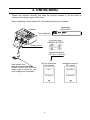
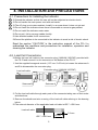
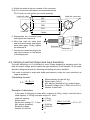
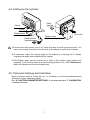
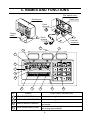
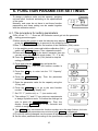
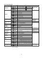
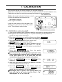
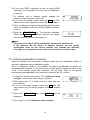
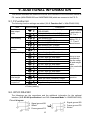
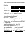
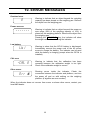
Weighing Indicator for Check Weighing Scales 1WMPD4002313 This Manual and Marks All safety messages are identified by the following, “WARNING” or “CAUTION”, of ANSI Z535.4 (American National Standard Institute: Product Safety Signs and Labels). The meanings are as follows: WARNING A potentially hazardous situation which, if not avoided, could result in death or serious injury. CAUTION A potentially hazardous situation which, if not avoided, may result in minor or moderate injury. This is a hazard alert mark. Note This manual is subject to change without notice at any time to improve the product. No part of this manual may be photocopied, reproduced, or translated into another language without the prior written consent of the A&D Company. Product specifications are subject to change without any obligation on the part of the manufacture. Copyright 2011 Contents 1. COMPLIANCE ................................................................................................. 2 2. INTRODUCTION .............................................................................................. 3 3. UNPACKING .................................................................................................... 4 4. INSTALLATION and PRECAUTIONS ............................................................. 5 4-1. Precautions for Installing the Indicator ...................................................... 5 4-2. Load Cell Connections .............................................................................. 5 4-3. Verifying Load Cell Output and Input Sensitivity........................................ 6 4-4. Setting Up the Indicator............................................................................. 7 4-5. Parameter Settings and Calibration .......................................................... 7 5. NAMES AND FUNCTIONS .............................................................................. 8 6. FUNCTION PARAMETER SETTINGS........................................................... 10 6-1. The procedure for setting parameters ..................................................... 10 6-2. Function list ..............................................................................................11 7. CALIBRATION ............................................................................................... 12 7-1. Calibration using a weight ....................................................................... 12 7-2. Gravity acceleration correction................................................................ 13 8. AUTO-TARE FUNCTION ............................................................................... 14 9. ADDITIONAL INFORMATION........................................................................ 15 9-1. F-Function list.......................................................................................... 15 9-2. OP-03 RS-232C ...................................................................................... 15 9-3. OP-04 RS-422 / 485................................................................................ 17 10. ERROR MESSAGES ................................................................................... 18 11. SPECIFICATIONS ........................................................................................ 19 11-1. Capacity and minimum display .............................................................. 19 11-2. Specifications ........................................................................................ 19 11-3. Options .................................................................................................. 20 11-4. Dimensions............................................................................................ 20 1 1. COMPLIANCE Compliance with FCC rules Please note that this equipment generates, uses and can radiate radio frequency energy. This equipment has been tested and has been found to comply with the limits of a Class A computing device pursuant to Subpart J of Part 15 of FCC rules. These rules are designed to provide reasonable protection against interference when equipment is operated in a commercial environment. If this unit is operated in a residential area it might cause some interference and under these circumstances the user would be required to take, at his own expense, whatever measures are necessary to eliminate the interference. (FCC = Federal Communications Commission in the U.S.A.) Classification of protection provided by enclosures The equipment is designed to comply with the IP Code of IEC 60529. The “IP65” is explained as follows: “IP” International Protection. “6” Against ingress of solid foreign objects. Dust-tight. No ingress of dust. “5” Against ingress of water with harmful effects. Protected against water jets (no powerful jets). Water projected in jets against the enclosure from any direction shall have no harmful effects. 2 2. INTRODUCTION This manual describes how this product works and how to get the most out of it in terms of performance. The FS-D weighing indicator is used to build high performance check weighing scales. It has similar specifications and functions as an indicator of the FS-i series. Please refer to the instruction manual for the FS-i supplied with the FS-D. The FS-D indicator has the following features. The indicator can be used to build platform scales from 6 kg (15 lb) capacity to 1500 kg (3500 lb) capacity. The indicator can drive up to 4 x 350 Ω load cells. Three weight display resolutions are available, 1/3,000, 1/6,000 (~1/7,500) and 1/12,000 (~1/15,000) to cover various applications. Weighing units are kg (kilogram), g (gram), lb (pound), oz (ounce), and lb-oz (pound and ounce). However, the FS-D set to a capacity higher than 30 kg (70 lb) does not have all of them. Refer to “11-1. Capacity and minimum display” in detail. Waterproof to IP-65 specifications. Constructed from stainless steel for harsh working environments. Large liquid crystal display with back lighting and analog sweep display of 60 segments with back lighting. AC power source (100V ~ 240V), and an optional SLA (sealed lead acid) battery is available for operation where AC power is not available. Built in comparator lights with large and bright red, green and yellow LEDs for better visibility. Two modes of comparator operation, Target weight setting and Upper / Lower limits setting. Take-away check weighing with auto-tare function. Optional serial data and comparator relay interface. 3 3. UNPACKING Unpack the indicator carefully and keep the packing material if you are likely to transport the indicator again in the future. When unpacking, check whether all of the following items are included: Model label (1083014607) Indicator To be attached. Connector plug (1JMNJW-165-PM7) Display stand Hexagonal wrench (1.27 mm / 0.05 inch) Main power cord Set Up Instruction (this manual) Please confirm that the main power type is correct for your local voltage and receptacle. Instruction manual FS-i series FS-D FS-i series SET UP INSTRUCTION INSTRUCTION MANUAL 4 4. INSTALLATION and PRECAUTIONS 4-1. Precautions for Installing the Indicator Ground the indicator so that the user will not be subjected an electric shock. Do not handle the main power cord with wet hands. The AC plug is not water-resistant. Install it in an area where it does not get wet. Do not install the indicator where there is flammable or corrosive gas present. Do not install the indicator under water. Do not pull, fold or arrange cables forcibly. Use shielded cables for all connections. Ground the platform to be connected to the indicator to avoid a risk of electric shock. Read the section “CAUTION” in the instruction manual of the FS-i to understand the conditions and precautions for installation, operation and cleaning the indicator. 4-2. Load Cell Connections Solder the load cell cable to the connector plug (1JMNJW-165-PM7) provided with the FS-D and connect it to the connector on the bottom of the FS-D. 1. Use the supplied hexagonal wrench (1.27 mm / 0.05 inch) to loosen the setscrews A and B to disassemble the connector plug. Load cell cable Setscrew B Connector plug (1JMNJW-165-PM7) Setscrew A Pin contacts 2. Put the load cell cable through each parts of the connector taking care of their order and directions. 3. Remove the sheath and wire covering of the load cell cable referring to the drawing below. The external diameter of the applicable load cell cable is Ø5.7 ~ Ø6.8 mm. Load cell cable 3.2 mm Ø5.7 ~ Ø6.8 mm 5 16 mm 4. Solder the wires to the pin contacts of the connector. A 5 m or less load cell cable is recommended as the FS-D uses a 4 wire system (no remote sensing). Load cell cable Load cell connector SIGEXC+ SIG+ EXC- Load cell Shield 5. Reassemble the connector plug and tighten the setscrew A. 6. Move the load cell cable back and forth and around, and tighten each parts again. Finally, tighten the setscrew B. Setscrew B Setscrew A 7. Connect the connector plug to the load cell connector on the bottom of the display pod. 4-3. Verifying Load Cell Output and Input Sensitivity The input sensitivity is 0.2 µV/division or more. When designing a weighing scale, the load cell output voltage should satisfy the input sensitivity of the indicator. Or the scale should be designed so that the following calculating formula is satisfied. In order to achieve a scale with stable performance, select the input sensitivity as large as possible. Calculating formula: 0.2 ≤ E× B×d A×n A: B: d : E: n: Rated capacity of load cell (kg) Rated output (mV/V) Min. display (smallest of kg) / scale division Excitation voltage (mV) = 5000 mV for FS-D Number of load cells Example of calculation: In the case of designing a scale with a capacity of 60 kg, using a load cell with a rated capacity of 100 kg and rated output of 1 mV/V: Load cell capacity: Rated output: Set function setting C02-3, then Min. display (smallest): Excitation voltage: Number of load cell: A = 100 kg B = 1 mV/V d = 0.005 kg E = 5000 mV n=1 6 5000 × 1 × 0.005 = 0.25 > 0.2 100 × 1 4-4. Setting Up the Indicator Earth terminal Clamp Clamp Display stand Earth terminal To the wall Display stand (Wall-mounting bracket) Connect the main power cord to an outlet that has an earth ground terminal. You may use the earth terminal on the rear side of the display to ground the indicator. If necessary, adjust the viewing angle of the display by loosening the 2 clamps, changing the angle and re-tightening the clamps. The Display stand can be secured on a table or flat surface using screws (not supplied). It can be also used as a wall-mounting bracket. See “11-3. Dimensions” about the dimensions of the mounting holes. 4-5. Parameter Settings and Calibration When a platform scale is initially set up, it is necessary to set some parameters and calibrate it using a calibration weight. See “6. FUNCTION PARAMETER SETTINGS” to set parameters and “7. CALIBRATION” to calibrate the scale. 7 5. NAMES AND FUNCTIONS CAL switch cover Cable hook Display pod Earth terminal Display stand Earth terminal Load cell connector 5 2 1 6 8 7 9 10 4 No. 3 4 11 NAMES 12 FUNCTIONS / OPERATION 1 WEIGHT DATA DISPLAY Indicates the weight data. 2 WEIGHING UNIT INDICATOR Indicates the weighing unit in use. 3 ANALOG WEIGHT DISPLAY 4 OVER RANGE INDICATORS Indicates zero to full scale or comparison limits and results. Turns ON when the weight is outside the range of the analog sweep display. 8 No. NAMES FUNCTIONS / OPERATION 5 COMPARISON INDICATORS Indicates the results of the weight comparison LO (RED), OK (GREEN) and HI (YELLOW). 6 STABLE ANNUNCIATOR Turns ON when the weight reading is STABLE. 7 ZERO ANNUNCIATOR 8 NET ANNUNCIATOR 9 PT ANNUNCIATOR 10 PRINT ANNUNCIATOR 11 PRECAUTION AGAINST LOW BATTERY 12 ON/OFF Key ZERO / ± Key TARE Key PT Key SAMPLE / 9 Key KEY / 8 Key RECALL / 7 Key HI / 6 Key LO / 5 Key STORE / 4 Key DISP. / 3 Key UNITS / 1 Key PRINT / ENT Key C Key 0 and 2 Keys Turns ON when the weight is in the center of ZERO range. Turns ON when the display shows the NET weight. Turns ON when the display shows the preset tare weight. Turns ON for a moment when the weight data is sent by the PRINT/ENT or auto-printing. Turns ON when the optional battery is getting close to low battery. Turns the power on or off. When turned on, the power-on zero will work. Zeroes the indicator when the weight is stable. Or the key switches the sign “+” & “-”. Zeroes the display and switches to net weight mode when the weight is plus and stable. The key is used to enter a tare weight via the 10-key pad. To register the sample weight as a target. Or the numeric key 9 in the data entry. To enter a target weight via the 10-key pad. Or the numeric 8 in the data entry. To recall target weight and/or HI/LO limits. Or the numeric 7 in the data entry. To enter comparator HI limit via the 10-key pad. Or the numeric 6 in the data entry. To enter comparator LO limit via the 10-key pad. Or the numeric 5 in the data entry. To store target weight and/or HI/LO limits. Or the numeric 4 in the data entry. Switches the analog sweep display modes. Or the numeric 3 in the data entry. To select the desired weighing unit. Or the numeric 1 in the data entry. To send a data string through the optional interface. Or to ENTER the numeric data. The key to clear an incorrect data entry from the numeric keypad. The numeric keys 0 and 2. 9 6. FUNCTION PARAMETER SETTINGS To design a platform scale, set the capacity, weighing unit and other functions according to the specifications of the scale. Normally, end users do not have to set these function parameters and these setting can be sealed together with the calibration switch. Parameter -C01-00 Function number 6-1. The procedure for setting parameters Do not set “C01-1”. Once set, the indicator cannot get into the parameter setting procedure again. When turning the power on and the indicator may display ------- , press the PRINT/ENT key to proceed to the weighing mode. See “7. CALIBRATION” as for the location of the calibration (CAL) switch. 1. In the weighing mode, press and hold the calibration (CAL) switch until Cal appears. Then, release the switch. Press and hold the 0 key for about 5 seconds, then you can also enter the calibration mode (when “C01-0” is set). Press the ON/OFF key or (CAL) switch to stop the setting procedure. -00Cal00 2. Press and hold the ZERO key and press the PRINT/ENT key. Then the first function number is displayed. -C01-01 3. Press the 2 setting. -C02-01 key to enter into the “C02 Capacity” 4. Press the PRINT/ENT stored appears. key. Then the parameter 5. Enter the parameter value for the capacity using the 10-key pad. 6. Press the ZERO key to go to the next function number “C03 Weighing display unit”. 7. Set C03 “0” (metric unit), or “1” (non-metric unit). 8. The settings C02 and C03 are minimum requirements to design a platform scale. To finalize the settings, be sure to press the PRINT/ENTER key. Then, the display shows end for a few seconds and returns to weighing mode. -C02-00 -C02-02 -C03-01 -00end00 The ZERO key increments the function number as in the step 6 above, but note that all of the new parameters are not stored until end is displayed. To exit with nothing changed, turn the power off without pressing the PRINT/ENT key. Set the other parameters according to the specifications required. 10 6-2. Function list Item Function number C01- 0 Calibration C01- 1 C01- 2 C02- 0 C02- 1 C02- 2 C02- 3 Capacity C02- 4 C02- 5 C02- 6 C02- 7 C03- 0 Weighing display unit C03- 1 C04- 0 Power-on-zero range C04- 1 Internal use C05- 0 C06- 0 Decimal separator C06- 1 C07- 0 Tare clear by ZERO operation C07- 1 Tare operation C08- 0 (Net weight calculation) C08- 1 C09- 0 Preset tare function C09- 1 C10- 0 lb-oz unit C10- 1 ZERO operation C11- 0 range C11- 1 C12- 0 C12- 1 Display resolution C12- 2 C12- 3 C13- 0 Auto-tare function C13- 1 Description CAL switch enabled, 0 key enabled CAL switch disabled, 0 key disabled CAL switch enabled, 0 key disabled 6 kg (15 lb) 15 kg (35 lb) 30 kg (70 lb) 60 kg (150 lb) 150 kg (350 lb) 300 kg (700 lb) 600 kg (1500 lb) 1500 kg (3500 lb) kg, g kg, g, lb, oz, lb-oz ±10% of the capacity ±50% of the capacity Do not change. . (point) , (comma) ZERO does not clear tare weight ZERO clears tare weight Tare weight is rounded to the weight display count Internal count is used for TARE weight. Function disabled Function enabled lb-oz disabled lb-oz enabled ±2% of the capacity Up to the capacity “f02” setting specifies the resolution. Fixed to “f02-0” (1/3,000~1/3,500) Fixed to “f02-1” (1/6,000~1/7,500) Fixed to “f02-2” (1/12,000~1/15,000) Function disabled Function enabled Factory setting 11 Do not set “C01-1” See “11-1. Capacity ...”. OIML R76 / NTEP OIML R76 NTEP OIML R76 C13-0 deletes “f21” ~ “f23”. 7. CALIBRATION This function adjusts the scale (indicator) for accurate weighing. Calibration must be done when the FS-D is initially connected to a load cell (base unit). Calibration may also be required according the changes in the environment. CAL switch cover When the scale (indicator) has been moved. When the ambient environment has significantly changed. For regular calibration. Loose the lock screws on the rear side of the display pod, and remove the (CAL) switch cover. The calibration switch inside. Calibration (CAL) switch 7-1. Calibration using a weight 1. Warm up the indicator with a weighing platform connected for at least half an hour. Change the user function setting “f01” or place something on the platform to disable the auto power-off function. When turning the power on and the indicator may display ------- , press the PRINT/ENT key to proceed to the weighing mode. 2. Press and hold the calibration (CAL) switch until Cal appears, and release the switch. Press and hold the 0 key for about 5 seconds, then you can also enter the calibration mode (when “C01-0” is set). Press the ON/OFF key or (CAL) switch to exit without calibration. 3. Press the PRINT/ENT key, then the gravity acceleration value will be displayed. It is not necessary to set the gravity acceleration value when calibrating the indicator with a calibration weight at the place where it is to be used. (See the next section about the gravity acceleration correction.) 4. Press the displayed. PRINT/ENT key, then Cal 0 will be -00Cal00 -009.7985 -00Cal00 5. Make sure that there is nothing on the platform, and wait until the STABLE indicator turns on. 6. Press the PRINT/ENT key. The indicator inputs the zero point, and the display shows 5pn 1 and the weight value for calibration (SPAN calibration). The weight value is equal to the capacity. When you enter with “kg” or “g” mode, then the value is “kg”. Entering with “lb” or “oz”, then “lb”. 12 -05pn010 -00030.00 If you need ZERO calibration but do not need SPAN calibration, turn the power off to exit from the calibration procedure. 7. To calibrate with a different weight, change the displayed value using the 10-key pad. If you enter the wrong number, press the C key. The value returns to the capacity and enter the number again. -00020.00 8. Place a calibration weight on the platform with the same value as displayed, and wait until the STABLE indicator turns on. 9. Press the PRINT/ENT key. The indicator calibrates SPAN and end will appear. Remove the weight from the platform, and turn the power off. -00end00 Note The value set in step 7 will be cleared after the power is switched off. If the indicator will be moved to another location, set the gravity acceleration value for the current location and calibrate the indicator according to the procedure above. See the next section to set the value. 7-2. Gravity acceleration correction When the indicator will be moved to different place from the calibration location, it should be calibrated using a calibration weight. But if a calibration weight is not available, the gravity acceleration correction will compensate the indicator. To use this function, set the gravity acceleration value to the value of the location where the calibration will be done. Refer to the gravity acceleration map appended to the instruction manual of the FS-i series. 1. At step 3 of the previous section “7-1. Calibration using a weight”, enter a new value using 10-key pad. The integral part “9” is fixed, enter the value after the decimal point. If you hit the wrong number, press the C key. The value returns to the original number. Enter the number again. 2. Press the displayed. PRINT/ENT key, then Cal 0 3. Go to step 5 of “7-1. Calibration using a weight”. 13 will be -009.8050 -00Cal00 8. AUTO-TARE FUNCTION The FS-D has an auto-tare function to be used with the comparator function enabled. If the weight value is within the OK range and stable for a preset time, then the indicator will automatically tare the weight and show zero. The Function “f22” designates the timing to tare automatically. See “9. ADDITIONAL INFORMATION” about the added F-Function settings related to the auto-tare function. To use the auto-tare function, set the function settings below. f08-1: f21-1: f22-0 ~ 9: Compare all weighing data (other settings may be used depending on the application). Auto-tare function enabled. Select the timing to tare automatically to avoid the wrong tare operation, for example; too early to tare, to take a longer time to go to the next weighing and so on. Take-away check weighing: Take-away check weighing (negative comparison) is the way to compare the negative weight taking away material from a container. Set the Function “f24-1” together with the auto-tare function enabled “f21-1”. In this operation mode, the indicator operates as “take-away the material” Æ “OK and stable” Æ “auto-tare” Æ “take-away the material” Æ ······. In this setting, the polarity of the target weight and the upper / lower limit weight are ignored and the indicator shows the comparator results as below. f07-1: -(|Target|+HI limit) f07-0: -|Upper limit| Negative value HI -(|Target|-LO limit) -|Lower limit| Net 0 OK Weight display LO Note To start the take-away check weighing, be sure to use the TARE key to tare the weight of the container filled with material. The ZERO key may zero the display, and the indicator goes below the zero point by taking out the material. Then, the auto-tare function does not work. When the Function “f23-1 Tares the initial (container) weight.” is set: To start the auto-tare function application, usually the container (filled with material) will be placed on the weighing pan and its weight must be tared using the TARE key. When the Function “f23-1” is set, the indicator will tare the initial (container) weight automatically. Remove all load on the weighing pan to return to the zero point, the tare weight will be automatically cleared. If the indicator could not return to the zero point because of a zero shift, press the ZERO key to clear the tare weight. If the indicator is equipped with the optional RS-232C interface, the OK weighing data only can be sent out automatically. Set the Function setting “f06-7 Auto-print mode +/- data”. 14 9. ADDITIONAL INFORMATION This section describes the additional functions and corrections to the instruction manual of FS-i series (WM+PD4001332 and 1WMPD4001368) which are common to the FS-D. 9-1. F-Function list The following function settings are added (“11-2. Function list” in WM+PD4001332). Item Serial interface Data output mode Function number f06- 5 Zero tracking Auto-tare function Auto-tare timing Auto-tare for the initial weight Normal/Negative comparison f06f06f13f13f13f13f21f21f22f22f22f22f22f22f22f22f22f22f23f23f24f24- 6 7 0 1 2 3 0 1 0 1 2 3 4 5 6 7 8 9 0 1 0 1 Description Multi-connection with print key mode (RS-422/485) Auto-print mode + data & OK Auto-print mode +/- data & OK Zero tracking OFF Zero tracking ON, 0.5d/sec Zero tracking ON, 1.0d/sec Zero tracking ON, 2.0d/sec Auto-tare function disabled. Auto-tare function enabled. Immediately after OK and stable 0.5 sec. after OK and stable 1.0 sec. after OK and stable 1.5 sec. after OK and stable 2.0 sec. after OK and stable 2.5 sec. after OK and stable 3.0 sec. after OK and stable 4.0 sec. after OK and stable 5.0 sec. after OK and stable 6.0 sec. after OK and stable Function disabled Tares the initial (container) weight. Normal comparison Negative comparison for take-away The UFC format is applicable to f06-2 to 4. Setting C04-0, f13-2 and 3 cannot be set. Timing to tare automatically after the comp. OK and weight stable. To be used with f21-1. Automatic operation. Factory setting 9-2. OP-03 RS-232C The followings are the corrections and the additional information for the optional interface (“2-2. OP-03 Specifications” and “2-3. Command Mode” in 1WMPD4001368). Circuit diagram 4 Signal ground SG 5 Shield 6 Frame ground FG 15 4 Signal ground SG 5 Frame ground FG 6 Shield The frame ground and the shield are connected internally and there is no difference between them in use. Data format Example of data Out of range “kg” (+) O L , + 9 9 9 9 9 9 9 9 _ k g CR LF Out of range “kg” (+) O L , + 9 9 9 9 . 9 9 9 _ k g CR LF The position of decimal point is different according to the model and/or “f02”. Example for the weighing unit “lb-oz” (added) Weighing data “lb-oz” (+) S T , + 0 0 1 L 0 1 . 6 _ o z CR LF Data output mode (f06) The commands can be used in all data output modes (f06-1 is command mode only). The new modes f06-5, f06-6 and f06-7 are added to the Function “f06”. Auto-print Mode + data and OK (f06-6) Data is sent if the weight display is stable at +5d (d = weighing display division) and above, and the comparator result OK in addition. The next transmission cannot occur until after the weight display falls below +5d. Auto-print Mode +/- data and OK (f06-7) Data is sent if the weight display is stable at ±5d (d = weighing display division) and above/below, and the comparator result OK in addition. The next transmission cannot occur until after the weight display falls between –5d and +5d. Multi-connection with Print key mode (RS-422/485) (f06-5) This is one of the applications when a PC and more than one FS-D (RS-422/485 installed) are connected. Refer to “Multi-connection with Print key mode” in detail. (In “2-3. Command Mode”) Examples of command and reply (“_” shows “Space” (20H).) There are corrections to the instruction manual 1WMPD4001368. Set a HI limit value or upper limit weight. (No reply for f20-1.) When f07-0 or f07-1 is set, the When f07-0 or f07-1 is set, the command command should have “+” and 6 should have “+/-” (“+” only for f07-1) and 6 digit number without decimal point. digit number without decimal point. Set a LO limit value or lower limit weight. (No reply for f20-1.) When f07-0 or f07-1 is set, the When f07-0 or f07-1 is set, the command command should have “+” and 6 should have “+/-” (“+” only for f07-1) and 6 digit number without decimal point. digit number without decimal point. When f07-2 is set, the command should have “+” and 5 digit number without decimal point. 16 Command H I , + 0 0 1 0 0 CR LF Assume 2 decimal place number. Reply H I , + 0 0 1 0 0 CR LF 1.00% will be set as LO limit %. Command L O , + 0 0 1 0 0 CR LF Assume 2 decimal place number. Reply L O , + 0 0 1 0 0 CR LF 1.00% will be set as LO limit %. Store the comparator limits into the specified memory number. (No reply for f20-1.) Reply H I , 0 1 , + 0 0 1 2 0 0 , + 0 0 0 9 0 0 CR LF Reply M L , 0 1 , + 0 0 1 2 0 0 , + 0 0 0 9 0 0 CR LF 9-3. OP-04 RS-422 / 485 The followings are the corrections and the additional information for the optional interface. (“3-2. OP-04 Specifications” in 1WMPD4001368). Circuit diagram 5 Shield 6 Frame ground FG 5 Frame ground FG 6 Shield The frame ground and the shield are connected internally and there is no difference between them in use. Multi-connection with Print key mode (new function) This is one of the applications when a PC and more than one FS-D are connected. The indicator will prepare the weighing data by pressing the PRINT key first and will send out the prepared data after receiving a command from the PC. 1. Set the Function “f06-5” for all of the indicators. 2. Weigh something and wait for the STABLE indicator to turn on (the indicator having f18-##). 3. Press the PRINT key, the indicator will temporarily store the weight data and turn the PRINT indicator on. The indicator does not accept the PRINT key while the PRINT indicator on. 4. Send the “@##S” command to the indicators from the PC. 5. The indicator (f18-##) will respond to the command to send the weight data in memory and turn the PRINT indicator off. The address ## = 23 (f18-23). A request for weight data. Command @ 2 3 S CR LF Reply @ 2 3 S T , + 0 0 1 2 . 3 4 5 _ k g CR LF Reply @ 2 3 I CR LF The indicator does not have any stored data to send. While the PRINT indicator is on, the indicator will send back “@##I” to commands other than “@##S” command. 17 10. ERROR MESSAGES Overload error ----e--- Warning to indicate that an object beyond the weighing capacity has been placed on the weighing pan. Remove the object from the weighing pan. Power-on error -------- Warning to indicate that an object beyond the power-on zero range (50% of the weighing capacity or 10%) is placed on the weighing platform. Remove the object from the weighing pan. Pressing the PRINT/ENT key, the indicator will show the weight value without zeroing the indicator. Low battery ---lb1-- Warning to show that the OP-02 battery is discharged. Immediately connect the power cord to the AC power source to charge the battery. The indicator can be used while the battery is charging (except when the OP-04 is installed). CAL error ---Cal-e Warning to indicate that the calibration has been canceled because the calibration weight is too light. Check if the calibration weight is correct. Other errors ---err-# Showing errors inside the indicator. Check the connection between the indicator and platform, and turn the power off and on with nothing on the weighing platform. (# signifies an error number.) When the indicator does not recover from errors or shows other errors, contact your local A&D dealer. 18 11. SPECIFICATIONS 11-1. Capacity and minimum display C02- setting Capacity kg Min. display Capacity g Min. display Capacity lb Min. display Capacity oz lboz Min. display Capacity Min. display 0* 1 6 15 0.002* 0.005 0.001 0.002 0.0005 0.001 6000 15000 2* 5 1 2 0.5 1 15 35 0.005* 0.01 0.002 0.005 0.001 0.002 240 560 0.1* 0.2 0.05 0.1 0.02 0.05 15 35 0.1 0.1 2 30 0.01 0.005 0.002 30000 10 5 2 70 0.02 0.01 0.005 1120 0.5 0.2 0.1 70 0.1 *: Factory setting 3 60 0.02 0.01 0.005 4 150 0.05 0.02 0.01 5 300 0.1 0.05 0.02 6 600 0.2 0.1 0.05 7 1500 0.5 0.2 0.1 NA NA NA NA NA 150 0.05 0.02 0.01 2400 1 0.5 0.2 350 0.1 0.05 0.02 5600 2 1 0.5 700 0.2 0.1 0.05 11200 5 2 1 1500 0.5 0.2 0.1 3500 1 0.5 0.2 NA NA NA NA NA NA NA NA: Not Available 11-2. Specifications Input sensitivity Input signal range Load cell excitation voltage Load cell drive capacity Temperature Zero coefficient Span Non-linearity Display Display update Operating temp. Power supply Dimension Weight 0.2 µV / d (d: the smallest Min. display of kg) 0 mV ~ 13 mV 5 V DC ±5% (no remote sensing) Up to 4 x 350 ohm load cells ±(0.2 µV ±0.001% of zero adjustment voltage) / °C (typ.) ±0.001% / °C of reading (typ.) ±0.01 % of full scale 7 segment LCD display (Character height 18.6 mm) with backlight 60 segment analog sweep display with backlight Approximately 20 times per second -10°C ~ 40°C / 14°F ~ 104°F, less than 85% R.H. AC main (100V ~ 240 V, 50/60 Hz) or SLA Battery (option) 250 (W) x 202 (D) x 266 (H) mm / 9.8 (W) x 8.0 (D) x 10.5 (H) in. Approximately 2.7 kg 19 11-3. Options OP-02 (HC-02i) OP-03 (FS-03i) OP-04 (FS-04i) SLA Battery (Yuasa Battery NP4-6 recommended.) RS-232C + Comparator Relay Output (See note.) RS-422/485 + Comparator Relay Output (See note.) Note OP-03 and OP-04 cannot coexist. 11-4. Dimensions Unit: mm 20 3-23-14 Higashi-Ikebukuro, Toshima-ku, Tokyo 170-0013 JAPAN Telephone: [81] (3) 5391-6132 Fax: [81] (3) 5391-6148 A&D ENGINEERING, INC. 1756 Automation Parkway, San Jose, California 95131 U.S.A. Telephone: [1] (408) 263-5333 Fax: [1] (408)263-0119 A&D INSTRUMENTS LIMITED <UK Office> Unit 24/26 Blacklands Way, Abingdon Business Park, Abingdon, Oxfordshire OX14 1DY United Kingdom Telephone: [44] (1235) 550420 Fax: [44] (1235) 550485 A&D INSTRUMENTS LIMITED <German Sales Office> Große Straße 13 b 22926 Ahrensburg Deutschland Telefon: [49] (0) 4102 459230 Telefax: [49] (0) 4102 459231 A&D Australasia Pty Ltd. 32 Dew Street, Thebarton, South Australia 5031 AUSTRALIA Telephone: [61] (8) 8301-8100 Fax: [61] (8) 8352-7409 A&D KOREA Limited 한국에이.엔.디(주) 대한민국 서울시 영등포구 여의도동 36-2 맨하탄 빌딩 8층 ( 8th Floor, Manhattan Bldg. 36-2 Yoido-dong, Youngdeungpo-ku, Seoul, KOREA ) 전화: [82] (2) 780-4101 팩스: [82] (2) 782-4280 A&D RUS CO., LTD. Компания ЭЙ энд ДИ РУС 121357, Российская Федерация, г.Москва, ул. Верейская, дом 17 ( Bldg. 17, Vereyskaya st., Moscow, 121357 RUSSIAN FEDERATION ) тел.: [7] (495) 937-33-44 факс: [7] (495) 937-55-66 A&D Instruments India Private Limited ( 509, Udyog Vihar, Phase- , Gurgaon - 122 016, Haryana, India ) : 91-124-4715555 : 91-124-4715599 BackCover 1WMPD4000058J