1
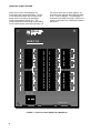
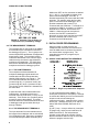
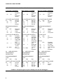
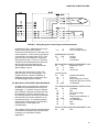
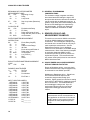
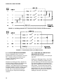
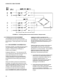
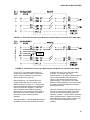
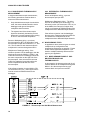
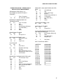
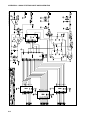
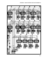
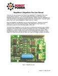
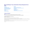
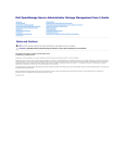
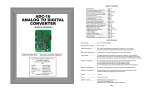
AM416 RELAY MULTIPLEXER
INSTRUCTION MANUAL
REVISION: 2/96
COPYRIGHT (c) 1987-1996 CAMPBELL SCIENTIFIC, INC.
WARRANTY AND ASSISTANCE
The AM416 RELAY MULTIPLEXER is warranted by CAMPBELL SCIENTIFIC, INC. to be free from
defects in materials and workmanship under normal use and service for twelve (12) months from date of
shipment unless specified otherwise. Batteries have no warranty. CAMPBELL SCIENTIFIC, INC.'s
obligation under this warranty is limited to repairing or replacing (at CAMPBELL SCIENTIFIC, INC.'s
option) defective products. The customer shall assume all costs of removing, reinstalling, and shipping
defective products to CAMPBELL SCIENTIFIC, INC. CAMPBELL SCIENTIFIC, INC. will return such
products by surface carrier prepaid. This warranty shall not apply to any CAMPBELL SCIENTIFIC, INC.
products which have been subjected to modification, misuse, neglect, accidents of nature, or shipping
damage. This warranty is in lieu of all other warranties, expressed or implied, including warranties of
merchantability or fitness for a particular purpose. CAMPBELL SCIENTIFIC, INC. is not liable for special,
indirect, incidental, or consequential damages.
Products may not be returned without prior authorization. To obtain a Returned Materials Authorization
(RMA), contact CAMPBELL SCIENTIFIC, INC., phone (435) 753-2342. After an applications engineer
determines the nature of the problem, an RMA number will be issued. Please write this number clearly on
the outside of the shipping container. CAMPBELL SCIENTIFIC's shipping address is:
CAMPBELL SCIENTIFIC, INC.
RMA#_____
815 West 1800 North
Logan, Utah 84321-1784
CAMPBELL SCIENTIFIC, INC. does not accept collect calls.
Non-warranty products returned for repair should be accompanied by a purchase order to cover the repair.
815 W. 1800 N.
Logan, UT 84321-1784
USA
Phone (435) 753-2342
FAX (435) 750-9540
www.campbellsci.com
Campbell Scientific Canada Corp.
11564 -149th Street
Edmonton, Alberta T5M 1W7
CANADA
Phone (403) 454-2505
FAX (403) 454-2655
Campbell Scientific Ltd.
Campbell Park
80 Hathern Road
Shepshed, Leics. LE12 9RP
ENGLAND
Phone (44)-50960-1141
FAX (44)-50960-1091
AM416 RELAY MULTIPLEXER MANUAL
TABLE OF CONTENTS
PAGE
1.
1.1
1.2
FUNCTION
Typical Applications ................................................................................................................... 1
Compatibility .............................................................................................................................. 1
2.
PHYSICAL DESCRIPTION .................................................................................................... 1
3.
AM416 SPECIFICATIONS...................................................................................................... 3
4.
OPERATION ............................................................................................................................... 3
4.1
4.2
5.
5.1
5.2
5.3
6.
6.1
6.2
6.3
6.4
6.5
6.6
6.7
The Control Terminals............................................................................................................... 3
The Measurement Terminals .................................................................................................... 6
DATALOGGER PROGRAMMING
Single Loop Instruction Sequence............................................................................................. 6
Multiple Loop Instruction Sequence .......................................................................................... 9
General Programming Considerations .................................................................................... 10
SENSOR HOOK-UP AND MEASUREMENT EXAMPLES
Single-Ended Analog Measurement without Sensor Excitation .............................................. 10
Differential Analog Measurement without Sensor Excitation................................................... 11
Half Bridge Measurements...................................................................................................... 11
Full Bridge Measurements....................................................................................................... 13
Full Bridges with Excitation Compensation ............................................................................. 13
Thermocouple Measurement .................................................................................................. 14
Mixed Sensor Types................................................................................................................ 16
7.
GENERAL MEASUREMENT CONSIDERATIONS ...................................................... 18
8.
INSTALLATION
8.1 Environmental Constraints................................................................................................................ 18
APPENDIX A. AM416 STUFFING CHART AND SCHEMATICS.....................................A-1
APPENDIX B. DIFFERENCES BETWEEN THE AM416 AND AM32 ............................B-2
LIST OF FIGURES
1.
2.
3.
4.
5.
6.
7.
8.
9.
10.
Plan View of the AM416 Relay Multiplexer................................................................................ 2
Hook-up Diagrams for Datalogger - AM416 Connections ......................................................... 4
Power and Ground Connections for External Power Supply..................................................... 5
Actuation Time of Relays vs. Temperature (o) and Battery Voltage.......................................... 6
Single Loop Instruction Sequence............................................................................................. 6
Example Program Loops for CR10(X), 21X, and CR7 Dataloggers ......................................... 8
Wiring Diagram for Strain Gages and Potentiometers .............................................................. 9
Single-ended Measurement without Excitation ....................................................................... 11
Differential Measurement without Excitation ........................................................................... 11
Half Bridge (Modified 107 Temperature Probe) Hook-up and Measurement.......................... 12
i
11.
12.
13.
14.
15.
16.
17.
Potentiometer Hook-up and Measurement ............................................................................. 12
Four Wire Half Bridge Hook-up and Measurement ................................................................. 13
Differential Measurement with Sensor Excitation .................................................................... 13
Full Bridge Measurement with Excitation Compensation ........................................................ 14
Differential Thermocouple Measurement with Reference Junction at the Datalogger ............ 15
Differential Thermocouple Measurement with Reference Junction at the AM416 .................. 15
Thermocouple and Soil Block Measurement........................................................................... 16
ii
CAUTIONARY NOTES
The AM416 is not designed to multiplex power. Its intended function is to switch low level analog
signals. Switched current in excess of 30 mA will degrade contacts and render them unsuitable for
future low level analog measurements. Customers who need to switch power are directed to CSI's
A6REL-12 or A21REL-12 relays.
Adjacent AM416 channels may be shorted together for up to 5 ms during the clocking procedure. Users
should consider this when assigning AM416 input channels. Sensors that are capable of sourcing
current should not be assigned input terminals adjacent to sensors that can sink current.
AM416 RELAY MULTIPLEXER
1. FUNCTION
The primary function of the AM416 Multiplexer
is to increase the number of sensors that may
be scanned by Campbell's CR10(X), 21X and
CR7 dataloggers. The AM416 is positioned
between the sensors and the datalogger;
mechanical relays are used to switch the
desired sensor signal(s) through the system.
Most commonly, users will multiplex signals
from analog sensors into single-ended or
differential datalogger channels. Four lines are
switched simultaneously; a maximum of sixteen
sets of (four) lines may be scanned, hence the
name A(nalog) M(ultiplexer) 4(lines x) 16(sets).
Therefore, a total of 64 lines may be
multiplexed.
The maximum number of sensors that can be
multiplexed through one AM416 depends
primarily upon the type(s) of sensors to be
scanned. Some examples (assuming identical
sensors) follow:
1. Up to 32 single-ended or differential
sensors that do not require excitation (e.g.
pyranometers, thermocouples; Sections
6.1, 6.2, and 6.6).
2. Up to 48 single-ended sensors that require
excitation (e.g. some half bridges; Section
6.3.1).
3. Up to 16 single-ended or differential
sensors that require excitation (e.g. full
bridges, four-wire half bridge with measured
excitation; Section 6.3.3 and 6.4).
4. In conjunction with an AM32 multiplexer, up
to 16 six-wire full bridges (Section 6.5).
1.1. TYPICAL APPLICATIONS
The AM416 is intended for use in applications
where the number of required sensors exceeds
the number of datalogger input channels. Most
commonly, the AM416 is used to multiplex
analog sensor signals, although it also may be
used to multiplex switched excitations,
continuous analog outputs, or even certain
pulse counting measurements (i.e. those that
require only intermittent sampling). It is also
possible to multiplex sensors of different, but
compatible, types (e.g. thermocouples and soil
moisture blocks, see Section 6.6).
NOTE: For a discussion of single-ended
versus differential analog measurements,
please consult the Measurement Section of
your datalogger manual.
As purchased, the AM416 is intended for use in
indoor, non-condensing environments. An
enclosure is required for field use. In nonthermocouple applications where a single
multiplexer is deployed, the AM-ENC enclosure
is recommended. In thermocouple applications,
CSI recommends use of the AM-ENCT
enclosure. If several multiplexers are deployed
at the same site in a non-thermocouple
application, the 024 or 030 enclosures provide
cost-effective housing options.
1.2 COMPATIBILITY
The AM416 is compatible with Campbell's
CR10(X), 21X or CR7 dataloggers.
The AM416 is compatible with a wide variety of
commercially available sensors. As long as
current limitations are not exceeded, and no
more than four lines are switched at a time,
system compatibility for a specific sensor is
determined by sensor-datalogger compatibility.
In CR10(X) applications, the AM416 may be
used to multiplex up to 16 Geokon vibrating wire
sensors through one AVW-1 vibrating wire
interface.
2. PHYSICAL DESCRIPTION
The AM416 is housed in a 21 cm x 16.5 cm x
3.5 cm (8.2" x 6.5" x 1.5") anodized aluminum
case (Figure 1). The aluminum case is
intended to reduce temperature gradients
across the AM416's terminal strips. This is
extremely important when thermocouples are
being multiplexed (Section 6.6). The case may
be opened by removing the four #1 phillipshead screws located at the corners of the case.
Disassembly of the case may be required to
mount the AM416 to a plate or an enclosure
(Section 8).
A strain-relief flange is located along the lower
edge of the top panel of the case. Several
plastic wire ties are included with the AM416 to
attach wires to this flange.
1
AM416 RELAY MULTIPLEXER
Wires from sensors and datalogger are
connected to the gray terminal strips. The set
of four terminals located near the strain-relief
flange are the connections for datalogger
control of the AM416 (Section 4.1). The
terminal strips that run the length of the AM416
are for measurement connections (Section 4.2).
The sensor inputs are not spark gapped. All
terminals accept stripped and tinned lead wires
up to 1.5 mm in diameter. The datalogger is
connected to the AM416 through a minimum of
seven, but generally nine, individually insulated
lead wires.
AM416
RELAY MULTIPLEXER
L2
H2
16
L1
H1
L2
H2
12
L1
H1
SHIELD
SHIELD
14
L2
H2
L1
H1
SHIELD
L2
H2
11
L1
H1
L2
SHIELD
H2
L1
H1
7
SHIELD
L2
H2
L1
H1
6
L2
H2
2
L1
H1
SHIELD
SHIELD
L2
L2
H2
L1
H1
H2
L1
H1
5
MADE IN USA
FIGURE 1. Plan View of the AM416 Relay Multiplexer
2
3
L2
12V
CLK
GND
SHIELD
L2
H2
L1
H1
H1
9
RES
13
4
SHIELD
L2
H2
10
L1
H1
SHIELD
8
L2
H2
L1
H1
L1
H2
L2
L2
H2
L1
H1
COM
COM
L2
H2
15
L1
H1
L2
H2
L1
H1
H2
1
L1
H1
AM416 RELAY MULTIPLEXER
3. AM416 SPECIFICATIONS
POWER*: unregulated 12 VDC (9.6 V to 16 V)
- See Figure 4 for implications of low power to
relay actuation
CURRENT DRAIN:
Quiescent: < 100 uA
Active: 17 mA (typical)
RESET*: a continuous signal of 3.5VDC <
voltage < 16 VDC holds AM416 in an active
state (i.e. a clock pulse can trigger a scan
advance). A signal voltage of < 0.9VDC
deactivates the AM416 (clock pulse will not
trigger a scan advance; AM416 is also reset).
CLOCK*: on the transition from <1.5 V to >3.5
V, scan advance is actuated on the leading
edge of the clock signal; clock signal must be a
minimum of 5 ms in width.
OPERATIONAL TEMPERATURE: -40oC to
+65oC
OPERATIONAL HUMIDITY: 0 - 95%, noncondensing
DIMENSIONS (without field enclosure):
length - 21 cm (8.2")
width - 16.5 cm (6.5")
depth - 3.5 cm (1.5")
(with field enclosure i.e. box size):
length - 25.4 cm (10.0")
width - 20.3 cm (8.0")
depth - 10.2 cm (4.0")
WEIGHT: 1.5 lbs (approx.)
(in enclosure): 10.0 lbs (approx.)
EXPANDABILITY**(nominal):
3 AM416'S/CR10(X)
4 AM416'S/21X
8 AM416's/CR7 725 Card
MAXIMUM CABLE LENGTH: sensor & scan
rate dependent (in general, longer lead lengths
necessitate longer measurement delays. Refer
to datalogger manual for additional details).
MAXIMUM SWITCHING CURRENT***: 500 mA
* Reset, Clock, and +12V inputs are limited to
+16V by 1.5KE20A transzorbs.
** Assumes sequential activation of multiplexers
and that each datalogger channel is uniquely
dedicated. If your application requires
additional multiplexing capability, please consult
CSI for application assistance.
*** Switching currents greater than 30 mA
(occasional 50 mA is acceptable) will degrade
the contact surfaces of the mechanical relays
(i.e. increase their resistance). This process will
adversely affect the suitability of these relays to
multiplex low voltage signals. Although a relay
used in this manner will not be of use in future
low voltage measurements, it may continue to be
used for switching current in excess of 30 mA.
CONTACT SPECIFICATIONS
Initial contact resistance: 50 mohm max.
Initial contact bounce: 1 ms max.
Contact material: Gold clad silver alloy
Electrostatic capacitance: 3pF
Minimum expected life:
Mechanical (at 50cps): 108 open
Electrical (at 20cps): 2 x 10⁵
CHARACTERISTICS (at 25oC, 50% Relative
Humidity)
Operate time 8 to 15 ms approx. (See Figure 4)
Release time 5 ms approx.
4. OPERATION
Subsection 4.1 discusses the use of the
terminals that control operation of the
multiplexer. These terminals are located along
the lower left side of the multiplexer as shown in
Figure 1. Subsection 4.2 discusses the use of
terminals used in sensor measurement.
4.1. THE CONTROL TERMINALS
The CR10(X), 21X and CR7 dataloggers should
be connected to the AM416 as shown in Figure
2. This figure depicts control connections;
measurement connections are discussed in
Section 6. The power, ground, reset, and clock
connections remain essentially the same
regardless of datalogger used.
In a CR10(X) application, the datalogger 12VDC
supply and ground terminals are connected to
the AM416 12V and ground terminals. Two
control ports are used for clock and reset.
3
AM416 RELAY MULTIPLEXER
FIGURE 2. Hook-up Diagrams for Datalogger - AM416 Connections
CR10(X) Hook-up 21X Hook-up
CR7 Hook-up
The 21X or CR7 (with a 725 Card) can be used
to connect 12VDC supply and ground to the
AM416. One control port is used for reset, and
one switched excitation channel is used for
clock. If switched excitations are unavailable, a
control port may be used to provide clock
pulses to the multiplexer.
4.1.1 RESET
Reset (RES) controls activation of the
multiplexer. A voltage (3.5VDC <voltage<
16VDC) applied to this terminal activates the
multiplexer. When this line is dropped to
<0.9VDC, the multiplexer enters a quiescent,
low current drain state. Reset is always
connected to a datalogger control port.
Instruction 86 (option code 41 - 48 [activate]
and 51 - 58 [deactivate]) is generally used.
With a 21X or CR7 with older PROMS,
Instruction 20 is commonly used to activate and
deactivate the multiplexer (set port high to
4
activate the multiplexer or low to enter
quiescent mode).
4.1.2 CLOCK
The multiplexer clock line (CLK) controls the
switching between sequential sets of relays.
When reset is set high and the multiplexer is
activated, the multiplexer's common lines (COM
H1, COM L1 COM H2, COM L2) are not
connected to any of the sensor input terminals.
When the first clock pulse is received, the
common lines are switched into connection with
multiplexer channel 1 (H1,L1,H2,L2). When a
second clock pulse is received, the common
lines are connected to multiplexer channel 2
(H1,L1,H2,L2). Adjacent Multiplexer input
channels are momentarily shorted to each other
during the switch (e.g. channel 1 H1 to channel
2 H1, channel 1 L1 to channel 2 L1, etc. See
Cautionary Notes). The multiplexer is clocked
on the leading edge of the voltage pulse. The
AM416 RELAY MULTIPLEXER
voltage level must fall below 1.5VDC then
exceed 3.5VDC to clock. Pulse width must be
at least 5 ms. An additional delay is required
before the measurement to ensure adequate
time for the relay to close.
In the 21X and CR7 dataloggers, a switched
excitation is generally used to clock the
multiplexer (Instruction 22 - 5,000 mV
excitation). If no switched excitation channels
are available it is possible to clock using control
ports. See Section 5.1 for additional details.
In the CR10(X) datalogger, a control port is
generally used to clock the multiplexer.
Instruction 86 with the pulse port option
(command code 71 through 78 - generates a
pulse 10 ms in width) may be used to clock the
multiplexer.
4.1.3 GROUND
The multiplexer ground terminal is connected to
datalogger power ground. If a separate power
supply is used, AM416 ground is also
connected to the power supply ground (Figure
3). The datalogger should always be tied to
earth ground by one of the methods described
in the Installation/Maintenance Section of your
datalogger manual.
and sensors) and the expected ambient
temperatures.
The power required to operate an AM416
depends on the percentage of time it is active.
For example, if a CR10(X) makes differential
measurements on 32 thermocouples every
minute, the average current drain due to the
AM416 is about 0.3 mA. Under the same
conditions, a 2 second scan rate increases the
average system current drain to about 8.5 mA.
At a minimum, the power supply must be able
to sustain the system between site visits over
the worst environmental extremes.
If a 21X power supply is used to power the
AM416, all low level analog measurements
(thermocouples, pyranometers, thermo-piles,
etc.) must be made differentially. This
procedure is required because slight ground
potentials are created along the 21X analog
terminal strip when the 12V supply is used to
power peripherals. This limitation reduces the
number of available analog input channels and
may mandate the use of an external supply for
the AM416 (Figure 3).
4.1.4 POWER SUPPLY
The AM416 requires a continuous 9.6 to 16
VDC power supply for operation. The
multiplexer's current drain is less than 100
microamps while quiescent and is typically 17
milliamps at 12 VDC when active. Power
supply connections are made at the terminals
labeled 12V and GND.
In many applications, it may be convenient to
power the AM416 from the datalogger's battery.
For more power-intensive operations, an
external, rechargeable, 12VDC, 60-AmpHr
source may be advisable. Because of their
ability to be recharged, lead-acid supplies are
recommended where solar- or AC- charging
sources are available. The datalogger alkaline
supply (7.5 AmpHr) can be used to power the
AM416 in applications where the system current
drain is low, or where frequently replacing the
batteries is not a problem. It is advisable to
calculate the total power requirements of the
system and the expected longevity of the power
supply based on the system current drains (e.g.
the datalogger, multiplexer, other peripherals
FIGURE 3. Power and Ground Connections
for External Power Supply.
Low power and high ambient temperatures may
affect the actuation time of the multiplexer
relays (Figure 4). If the relay is not closed when
a measurement is started, the result will be an
inaccurate or overranged value.
5
AM416 RELAY MULTIPLEXER
FIGURE 4. Actuation Time of Relays vs.
Temperature (oC) and Battery Voltage.
4.2 THE MEASUREMENT TERMINALS
The terminals that run the length of the AM416
are dedicated to the connection of sensors to
the datalogger (Figure 1). The 16 groups of 4terminal inputs allow attachment of stripped and
tinned sensor leads. The terminals marked
COM allow attachment of the common signal
leads that carry the sensor's signal between
multiplexer and datalogger. The shield lines
allow sensor shields to be routed through the
multiplexer and back to datalogger ground.
Within each SET, the four terminals are labeled
H1, L1, H2, L2. As the AM416 receives clock
pulses from the datalogger, each SET is
switched sequentially into contact with the COM
terminals. For example, when the first clock
pulse is received from the datalogger, SET 1
(bracket annotated with a number 1) is
connected with the COM lines. T terminal H1 is
connected to COM H1, terminal L1 to COM L1,
terminal H2 to COM H2, and terminal L2 to
COM L2. When the second clock pulse is
received, the first SET is switched out
(becomes an open circuit) and the second SET
(bracket annotated with a number 2) is
connected to the COM terminals.
5. DATALOGGER PROGRAMMING
When a number of similar sensors are
multiplexed and measured, the Instructions to
clock the AM416 and to measure the sensors
are entered within a program loop. The
generalized structure of a program loop is
outlined below:
5.1 SINGLE LOOP INSTRUCTION SEQUENCE
4.2.1 THE COM TERMINALS
The multiplexer terminals dedicated to
multiplexer-datalogger signal transfer are
located within the silk screened brackets
labeled COM (common; see Figure 1). The
four individual COM lines are labeled: H1
(common high #1), L1 (common low #1), H2
(common high #2), and L2 (common low #2).
The circuitry of each COM line is isolated from
the other three.
A shield terminal is also located within each
COM bracket. All shield terminals are in
electrical continuity at all times (i.e. they are not
switched). Their function is to provide a path to
ground for sensor cable shields. The shield
terminals within the COM bracket should be tied
to datalogger earth ground either directly or
through a busbar.
4.2.2 THE SENSOR INPUT TERMINALS
The input terminals for sensor attachment run
the length of the multiplexer and are subdivided
into 16 labeled groups. Each group consists of
four Simultaneously Enabled Terminals (SET).
6
FIGURE 5. Single Loop Instruction Sequence
(1 and 9) Activate/Deactivate AM416 - The
control port connected to reset (RES) is set high
to activate the AM416 prior to the measurement
sequence and set low following the
measurement loop(s). Instruction 86 is used to
set the port. (With the CR10(X), 21X, and CR7
without OS series PROMS, Instruction 20 is
used.)
(2 and 7) Loop - A loop is defined by Instruction
87 (begin loop), and by an end instruction, 95.
Within Instruction 87, the 2nd parameter
(iteration count) defines the number of times
that the instructions within a loop are executed
before the program exits the loop.
AM416 RELAY MULTIPLEXER
(3) Clock/Delay - With the CR10(X), the clock
line is connected to a control port. Instruction
86 with the pulse port command (71- 78), sets
the clock line high for 10 ms. Instruction 22 is
used to delay an additional 10 ms.
When controlled by the 21X or CR7, the clock
line may be connected to either an excitation or
a control port. Connection to an excitation port
is preferred because only one instruction (22) is
required to send the clock pulse. Instruction 22
should be programmed to provide a 10ms delay
with a 5000mV excitation. A control port can be
used to clock the AM416 if no excitation ports
are available. The 21X and CR7 instruction
sequence required to clock with a control port
is: Instruction 20 (set port high), Instruction 22
(delay of 20 ms without excitation) followed by
Instruction 20 (set port low).
(4) Step Loop Index - This instruction is used
when a measurement instruction within that
loop has more than one repetition. It allows
each measurement value to occupy a
sequentially assigned input location without
being overwritten by subsequent passes
through the loop. Without this instruction, each
indexed input location within the loop will
advance by only one location per loop iteration.
For Example: 2 sensors per SET, 6 sensors
total; two reps in measurement instruction; two
measurement values assigned to indexed input
locations (--); P90 step of 2. Loop count of
three.
First pass:
Second pass:
Third pass:
Input locations
1 2 3 4 5 6
1 2
3 4
5 6
sensor
numbers
Given the same program without a step loop
instruction, the following situation results:
First pass:
Second pass:
Third pass:
Input locations
1 2 3 4 5 6
1 2
3 4
5 6
sensor
numbers
The measurement values for the 2nd and 4th
sensors will be overwritten in their input
locations. The 1st, 3rd, 5th, and 6th
measurement values will reside in the first 4
input locations.
The Step Loop Instruction 90 is available in
CR10(X)s, CR7s, and 21Xs with a third PROM.
For 21X dataloggers without a third prom (i.e.
without Instruction 90), a separate
measurement instruction (with one rep) is
required for each sensor measured within the
loop. The input location parameter within both
measurement instructions is indexed.
For Example: 2 sensors per SET; one rep in
each of two measurement instructions; two
measurement values assigned to indexed input
locations (--), one begins with input location 1,
the other with input location 4; no P90. A total
of six sensors to be measured; loop count is
three.
First pass:
Second pass:
Third pass:
Input locations
1 2 3 4 5 6
1
2
3
4
5
6
sensor
numbers
A potential drawback of this technique is that
sequential sensors (i.e. those input to the same
SET) will not have sequential input locations.
(5) Measure - Enter the instruction needed to
measure the sensor(s) [see Section 6, Sensor
Hook-Up & Measurement Examples]. The input
location parameter of a measurement
instruction is indexed if a (--) appears to the
right of the input location. Index an input
location by pressing "C" after keying the
location. Indexing causes the input location to
be incremented by 1 with each pass through the
loop. This allows the measurement value to be
stored in sequential input locations. Instruction
90, as explained above, allows the indexed
input location to be incremented in integer steps
greater than 1.
NOTE: If more than 28 input locations are
utilized, then additional input locations must
be assigned using the datalogger *A mode.
Consult your datalogger manual for details.
(6) Optional Processing - Additional processing
is sometimes required to convert the reading to
the desired units. It may be more efficient or
reduce measurement time if this processing is
done outside the measurement loop. A second
loop can be used for processing, if necessary.
7
AM416 RELAY MULTIPLEXER
EXAMPLE PROGRAMS - GENERALIZED PROGRAM LOOPS FOR THE CR10(X), 21X AND CR7.
21X SAMPLE PROGRAM
*
1
Table 1
Programs
01:
60
Sec.
Execution
Interval
CR7 SAMPLE PROGRAM
*
1
Table 1
Programs
01:
60
Sec.
Execution
Interval
CR10(X) SAMPLE PROGRAM
*
1
Table 1
Programs
01:
60
Sec.
Execution
Interval
ACTIVATES MULTIPLEXER
01:
P20
Set Port
01:
1
Set high
02:
1
Port
Number
ACTIVATES MULTIPLEXER
01:
P20
Set Port
01:
1
Set high
02:
1
EX Card
03:
1
Port No.
ACTIVATES MULTIPLEXER
01:
P86
Do
01:
41
Set high
Port 1
BEGINS MEASUREMENT
LOOP
02:
P87
Beginning
of Loop
01:
0
Delay
02:
16
Loop Count
BEGINS MEASUREMENT
LOOP
02:
P87
Beginning
of Loop
01:
0
Delay
02:
16
Loop Count
BEGINS MEASUREMENT
LOOP
02:
P87
Beginning
of Loop
01:
0
Delay
02:
16
Loop Count
CLOCK PULSE AND DELAY
03:
P22
Excitation
with Delay
01:
1
EX Chan
02:
1
Delay w/EX
(units=.01
sec)
03:
1
Delay after
EX (units=
.01 sec)
04: 5000
mV
Excitation
CLOCK PULSE AND DELAY
03:
P22
Excitation
with Delay
01:
1
EX Card
02:
2
EX Chan
03:
1
Delay w/EX
(units=.01
sec)
04:
1
Delay after
EX (units=
.01 sec)
05: 5000
mV
Excitation
CLOCK PULSE
03:
P86
01:
72
04: USER SPECIFIED
MEASUREMENT
INSTRUCTION
04: USER SPECIFIED
MEASUREMENT
INSTRUCTION
04: USER SPECIFIED
MEASUREMENT
INSTRUCTION
ENDS MEASUREMENT
LOOP
05:
P95
End
ENDS MEASUREMENT
LOOP
05:
P95
End
ENDS MEASUREMENT
LOOP
05:
P95
End
DEACTIVATES MULTIPLEXER
06:
P20
Set Port
01:
0
Set low
02:
1
Port
Number
DEACTIVATES MULTIPLEXER
06:
P20
Set Port
01:
0
Set low
02:
1
EX Card
03:
1
Port No.
DEACTIVATES MULTIPLEXER
06:
P86
Do
01:
51
Set low
Port 1
Do
Pulse Port
2
DELAY
P22
01:
02:
03:
04:
1
0
1
0
Excitation
with Delay
EX Chan
Delay w/EX
Delay after EX
mV
Excitation
FIGURE 6. Example Program Loops for CR10(X), 21X and CR7 Dataloggers.
8
AM416 RELAY MULTIPLEXER
FIGURE 7. Wiring Diagram for Strain Gages and Potentiometers
(8) Additional Loops - Additional loops may be
used if sensors that require different
measurement instructions are connected to the
same multiplexer. In this instance, like sensors
are assigned to sequential input SETS. Each
group of sensors is measured in a separate
loop (steps 2 through 7, Figure 4). Each loop
contains clock and measurement instructions,
and all loops must reside between the
instructions that activate and deactivate the
AM416 (Steps 1 and 9).
The instruction sequence for control of an
AM416 is given on the following page. The
Program format is a product of EDLOG, a
datalogger program editor contained in CSI's
PC208 Datalogger Support Software.
5.2 MULTIPLE LOOP INSTRUCTION SEQUENCE
As shown above, the program for operation of
the AM416 is essentially the same for all CSI
dataloggers. To measure sensors of different
types, different measurement instructions may
be used within successive program loops. In
the following example, each loop is terminated
with Instruction 95, and the multiplexer is not
reset between loops. The following example
demonstrates measurement of two dissimilar
sensor types (i.e. strain gages and
potentiometers).
The program and accompanying wiring diagram
are intended as examples only; users will find it
necessary to modify both for specific
applications.
*
01:
1
60
Table 1 Programs
Sec. Execution Interval
ENABLES MULTIPLEXER
01:
P20
Set Port
01:
1
Set high
02:
1
Port Number
BEGINS STRAIN GAGE MEASUREMENT LOOP
02:
P87
Beginning of Loop
01:
0
Delay
02:
10
Loop Count
CLOCK PULSE
03:
P22
01:
1
02:
1
03:
1
04: 5000
Excitation with Delay
EX Chan
Delay w/EX (units=.01sec)
Delay after EX (units=.01sec)
mV Excitation
FULL BRIDGE MEASUREMENT INSTRUCTION
04:
P6
Full Bridge
01:
1
Rep
02:
3
50 mV slow Range
03:
1
IN Chan
04:
2
Excite all reps w/EXchan 2
05: 5000
mV Excitation
06:
1-Loc [:STRAIN #1]
07:
1
Mult
08:
0
Offset
END OF STRAIN GAGE MEASUREMENT LOOP
05:
P95
End
9
AM416 RELAY MULTIPLEXER
BEGINNING OF POTENTIOMETER
MEASUREMENT LOOP
06:
P87
Beginning of Loop
01:
0
Delay
02:
6
Loop Count
07:
01:
P90
2
CLOCK PULSE
08:
P22
01:
1
02:
1
03:
1
04: 5000
Step Loop Index (Extended)
Step
Excitation with Delay
EX Chan
Delay w/EX (units=.01sec)
Delay after EX (units=.01sec)
mV Excitation
POTENTIOMETER MEASUREMENT
INSTRUCTION
09:
P4
Excite,Delay,Volt(SE)
01:
2
Reps
02:
5
5000 mV slow Range
03:
1
IN Chan
04:
2
Excite all reps w/EXchan 2
05:
1
Delay (units .01sec)
06: 5000
mV Excitation
07:
11-Loc [:POT #1 ]
08:
1
Mult
09:
0
Offset
END OF POTENTIOMETER MEASUREMENT
LOOP
10:
P95
End
DISABLES MULTIPLEXER
11:
P20
Set Port
01:
0
Set low
02:
1
Port Number
12:
P
End Table 1
INPUT LOCATION LABELS:
1:STRAIN #1
13:POT #3
2:STRAIN #2
14:POT #4
3:STRAIN #3
15:POT #5
4:STRAIN #4
16:POT #6
5:STRAIN #5
17:POT #7
6:STRAIN #6
18:POT #8
7:STRAIN #7
19:POT #9
8:STRAIN #8
20:POT #10
9:STRAIN #9
21:POT #11
10:STRAIN#10
22:POT #12
11:POT #1
23:_________
12:POT #2
24:_________
10
5.3 GENERAL PROGRAMMING
CONSIDERATIONS
The excitation voltage, integration and delay
times associated with reading the signal, and
the speed with which the channels are switched
may be varied with the datalogger program. In
general, longer delay times are necessary when
the sensor and datalogger are separated by
long lead lengths. Consult your datalogger
manual for additional information on these
topics.
6. SENSOR HOOK-UP AND
MEASUREMENT EXAMPLES
This section covers sensor-AM416 connections
as well as AM416-datalogger measurement
connections. The following are examples only,
and should not be construed as the only way to
make a particular measurement. See the
Measurement Section of your datalogger
manual for more information on the basic bridge
measurements. Most of the following examples
do not depict datalogger-AM416 control
connections (Section 4), but their presence is
implied and required. CSI recommends that
only sensor shield (drain) wires be connected to
AM416 shield terminals.
6.1 SINGLE-ENDED ANALOG MEASUREMENT
WITHOUT SENSOR EXCITATION
Sensor to Multiplexer wiring - up to two singleended sensors that don't require excitation may
be connected to one AM416 input SET.
Multiplexer to Datalogger wiring - Signal lines
from COM terminals are input into two
consecutive single-ended analog input
channels. Signal ground lines are tied to analog
ground (AG) in the CR10(X), datalogger ground
in the 21X and CR7. The COM shield line is
tied to datalogger earth ground. Up to 32
single-ended sensors may be used by two
single-ended datalogger channels in this
manner.
NOTE: Low level single-ended
measurements are not recommended in a
21X application in which the 21X's internal
12VDC supply is being used to power the
multiplexer or other peripherals (Section
4.1.4).
AM416 RELAY MULTIPLEXER
FIGURE 8. Single-ended Measurement Without Excitation
FIGURE 9. Differential Measurement Without Excitation
6.2 DIFFERENTIAL ANALOG MEASUREMENT
WITHOUT SENSOR EXCITATION
Sensor to Multiplexer wiring - Up to two
differential sensors that don't require excitation
may be connected to one input SET. Sensor
shields are routed through shield terminals.
Multiplexer to Datalogger wiring - A pair of
COM terminals (e.g. COM H1 and COM L1) is
connected to a differential analog input at the
datalogger. Up to 32 differential sensors may
be measured by two differential datalogger
channels in this way.
6.3 HALF BRIDGE MEASUREMENTS
Measurements of this type may be subdivided
into three categories based on completion
resistance and the presence or absence of
measured excitation. If the sensor's completion
resistor(s) are installed at the datalogger panel
(e.g. a CSI 107 probe modified for multiplexer
use), then three probes per SET may be excited
and measured (Figure 10). However, if the
circuit is completed within the sensor (e.g.
potentiometers), then excitation, wiper signal,
and ground must be multiplexed. Because
excitation and ground may be multiplexed in
common, up to two sensors per SET may be
measured (Figure 11). If measured excitation is
required (i.e. four wire half-bridge), then only
one sensor per SET may be measured (Figure
12).
6.3.1 HALF BRIDGE MEASUREMENT WITH
COMPLETION RESISTOR(S) AT
DATALOGGER
Sensor to Multiplexer wiring - up to three half
bridges may be connected to one input SET,
provided that the sensor's completion resistors
are located at the datalogger (Figure 10).
Multiplexer to Datalogger wiring - Signal lines
from the multiplexer COM terminals are input
into three consecutive single-ended analog
input channels. A precision completion resistor
ties the analog input channel to analog ground
in the CR10(X) or to datalogger ground in the
21X or CR7.
11
AM416 RELAY MULTIPLEXER
FIGURE 10. Half Bridge (Modified 107 Temperature Probe) Hook-up and Measurement.
FIGURE 11. Potentiometer Hook-up and Measurement
6.3.2 POTENTIOMETER MEASUREMENT
Sensor to Multiplexer wiring - up to two
potentiometers may be connected to one input
SET. Excitation and ground leads may be
common; signal leads must be routed
separately (Figure 11).
Multiplexer to Datalogger wiring - Signal lines
from two COM terminals are connected to two
consecutive single-ended analog input
channels. One COM terminal is connected to a
datalogger switched excitation channel, and the
remaining COM line connects to datalogger
ground. Up to 32 potentiometers may be
measured by two single-ended datalogger
channels.
12
6.3.3 FOUR WIRE HALF BRIDGE WITH
MEASURED EXCITATION
Sensor to Multiplexer Wiring - one sensor per
input SET.
Multiplexer to Datalogger Wiring - One COM
line is tied to a datalogger excitation channel,
and two COM lines to a differential analog input.
The remaining COM line is connected to the
high side of a differential channel along with a
fixed resistor. The other side of the resistor
connects to the low side of the channel, then
ground (Figure 12). Up to 16 four wire halfbridges may be measured by two differential
datalogger channels in this manner.
AM416 RELAY MULTIPLEXER
FIGURE 12. Four Wire Half Bridge Hook-up and Measurement
FIGURE 13. Differential Measurement with Sensor Excitation
6.4 FULL BRIDGE MEASUREMENTS
Sensor to Multiplexer wiring - Excitation,
ground, and the two signal leads may be
connected to one input SET (Figure 13).
Multiplexer to Datalogger wiring - COM
terminals are connected to a datalogger
excitation channel, a differential analog input
channel, and analog ground. Up to sixteen full
bridges may be multiplexed through the AM416.
6.5 FULL BRIDGES WITH EXCITATION
COMPENSATION
Sensor to Multiplexer wiring - In a six wire
measurement, two wires must bypass the
AM416. One solution is to multiplex the four
signal wires through the AM416, but bypass the
AM416 with excitation and ground. This means
that the sensors will be excited in common,
which causes a higher current drain, possibly
exceeding the current available from the
datalogger's excitation channels. Alternatively,
the excitation and ground leads may be
multiplexed through either an AM32 multiplexer
or an additional AM416. This allows the
sensors to be excited one at a time (Figure 14).
Multiplexer to Datalogger wiring - Four leads
from the COM terminals to two sequential
differential analog channels in the datalogger.
Excitation and ground are multiplexed by a
AM32 or AM416. Both multiplexers can be
reset and clocked by the same control ports
and/or excitation channels, which simplifies
programming.
13
AM416 RELAY MULTIPLEXER
FIGURE 14. Full Bridge Measurement with Excitation Compensation
6.6 THERMOCOUPLE MEASUREMENT
The datalogger manuals contain thorough
discussions of thermocouple measurement and
error analysis. These topics will not be covered
here.
6.6.1 MEASUREMENT CONSIDERATIONS
Reference Junction - As shown in Figure 15 and
16, two reference junction configurations are
possible: reference at the datalogger or
reference at the AM416.
Datalogger Reference - The 21X and the CR7
723-T Analog Input card with RTD have built-in
temperature references. The 10TCRT
Thermocouple Reference (not standard with
CR10(X) purchase), is installed on the wiring
panel between the two analog input terminal
strips.
When the reference junction is located at the
datalogger, the signal wires between the datalogger and the AM416 must be of the same wire
type as the thermocouple (Figure 15). The
"polarity" of the thermocouple wire must be
maintained on either side of the multiplexer
(e.g. if constantan wire is input to a L1 terminal,
then a constantan wire should run between the
14
multiplexer's COM L1 terminal and the
datalogger measurement terminal). Figures 15
& 16 depict type T thermocouple applications,
but other thermocouple types (e.g. E, J, and K)
may also be measured and linearized by the
dataloggers.
If thermocouples are measured with respect to
the datalogger reference, then concurrent
measurement of any other sensor type through
the AM416 is not recommended. Two problems
will be encountered if this is done. Both
problems result from the compositional
differences of the thermocouple wires.
1. An extraneous thermocouple voltage will be
added to the non-thermocouple signal at
the junction of dissimilar metals (e.g. the
multiplexer COM terminals). The
magnitude of this signal will vary with the
temperature difference between the
datalogger and the AM416.
2. Some thermocouple wires have a greater
resistance than copper, which adds
resistance to the non-thermocouple sensor
circuit. For example, constantan is
approximately 26 times more resistive than
copper.
AM416 RELAY MULTIPLEXER
FIGURE 15. Differential Thermocouple Measurement with Reference Junction at the Datalogger.
FIGURE 16. Differential Thermocouple Measurement with Reference Junction at the AM416.
If a mix of TC's and other sensor types are
multiplexed through the AM416, it is generally
best to locate the reference junction on the
AM416, as shown in Figure 16.
AM416 Reference - An external reference,
usually a thermistor, may be located at the
AM416, as shown in Figure 16. This approach
requires an additional single-ended datalogger
input to measure the reference. Locate the
reference between the COM terminals and,
when practical, measure the thermocouples on
SETs that are in close proximity to the COM
terminals in order to minimize thermal
gradients.
Thermal Gradients - Thermal gradients between
the AM416's sensor input terminals and COM
terminals can cause errors in thermocouple
readings. For example, with type T
thermocouples, a one degree gradient between
input terminals and the COM terminals will
result in a one degree measurement error
(approximately). The aluminum cover plate
helps to minimize gradients, but for best results,
the AM416 should be shielded and insulated
from thermal sources.
When an enclosure is used, gradients induced
from heat conducted along the thermocouple
wire can be minimized by coiling some wire
inside the enclosure. This procedure allows the
heat to dissipate before it reaches the terminal.
If the AM416 is housed in a field enclosure, the
enclosure should be shielded from solar
radiation.
15
AM416 RELAY MULTIPLEXER
6.6.2 SINGLE-ENDED THERMOCOUPLE
MEASUREMENT
6.6.3 DIFFERENTIAL THERMOCOUPLE
MEASUREMENT
In single-ended thermocouple measurement,
the following precautions must be taken to
ensure accurate measurement:
Sensor to Multiplexer wiring - up to two
thermocouples per input SET.
1. Only shielded thermocouple wire should be
used; the sensor shields should be tied to
datalogger earth ground through the
multiplexer shield terminals.
2. The exposed end of the thermocouple
should be electrically insulated to prevent
differences in ground potential from causing
an error in the measured temperature.
Sensor to Multiplexer wiring - up to three
thermocouples per SET; the high side of each
thermocouple is input into terminals H1, L1, and
H2. The low sides of each thermocouple are
multiplexed in common through terminal L2.
Multiplexer to Datalogger wiring - If the
reference junction is at the datalogger, then the
wire that connects the COM H1, COM L1, and
COM H2 terminals to the datalogger should be
the same composition as the high side of the
thermocouples. Also, the wire that connects
COM L2 to datalogger ground should be the
same composition as the low side of the
thermocouples.
If the reference junction is at the AM416 (CSI
107 thermistor, RTD, etc.), then copper wire is
used to connect all COM terminals to the
datalogger.
Multiplexer to Datalogger wiring - The wires
here can be handled in one of two ways. If a
reference junction (107 thermistor, RTD, etc.) is
at the AM416, then two pair of copper wires
may be run between the COM terminals of the
multiplexer and two differential input channels.
If the reference junction is at the datalogger,
then two pairs of thermocouple wire should be
run between the COM terminals of the
multiplexer and two differential input channels.
6.7 MIXED SENSOR TYPES
In applications where sensors types are mixed,
multiple hook-up configurations and
programming sequences are possible. Please
consult CSI for application assistance if you
intend to multiplex markedly different sensor
types in your application.
6.7.1 MIXED SENSOR EXAMPLE: SOIL
MOISTURE BLOCKS AND
THERMOCOUPLES
In this example, 16 thermocouples and 16 soil
moisture blocks will be multiplexed through the
AM416. One thermocouple and one soil
moisture block are input into each SET.
FIGURE 17. Thermocouple and Soil Block Measurement
16
AM416 RELAY MULTIPLEXER
EXAMPLE PROGRAM - THERMOCOUPLE
AND SOIL BLOCK MEASUREMENT
(PROGRAM IS FOR CR10(X) - 33
LOCATIONS ALLOCATED TO INPUT
STORAGE)
*
01:
1
60
Table 1 Programs
Sec. Execution Interval
REFERENCE TEMPERATURE FOR
THERMOCOUPLES
01:
P11
Temp 107 Probe
01:
1
Rep
02:
4
IN Chan
03:
1
Excite all reps w/EXchan 1
04:
1
Loc [:REFTEMP ]
05:
1
Mult
06:
0
Offset
ENABLES MULTIPLEXER
02:
P86
Do
01:
41
Set high Port 1
BEGINS MEASUREMENT LOOP
03:
P87
Beginning of Loop
01:
0
Delay
02:
16
Loop Count
MEASURES 1 SOIL MOISTURE BLOCK PER
LOOP
07:
P5
AC Half Bridge
01:
1
Rep
02:
14
250 mV fast Range
03:
3
IN Chan
04:
2
Excite all reps w/EXchan 2
05: 250
mV Excitation
06:
18-Loc [:SOIL M #1]
07:
1
Mult
08:
0
Offset
ENDS MEASUREMENT LOOP
08:
P95
End
DISABLES MULTIPLEXER
09:
P86
Do
01:
51
Set low Port 1
CALCULATES BRIDGE TRANSFORM ON
SOIL MOISTURE BLOCKS
10:
P59
BR Transform Rf[X/(1-X)]
01:
16
Reps
02:
18
Loc [:SOIL M #1]
03:
1
Multiplier (Rf)
11:
P
End Table 1
INPUT LOCATION LABELS:
CLOCK PULSE
04:
P86
01:
72
05:
01:
02:
03:
04:
05:
P22
1
2
0
1
0
Do
Pulse Port 2
Excitation with Delay
EX Chan
Delay w/EX (units=.01 sec)
Delay after EX (units=.01 sec)
mV Excitation
MEASURES 1 THERMOCOUPLE PER LOOP
06:
P14
Thermocouple Temp
(DIFF)
01:
1
Rep
02:
1
2.5 mV slow Range
03:
1
IN Chan
04:
1
Type T (Copper-Constantan)
05:
1
Ref Temp Loc REFTEMP
06:
2-Loc [:TC #1 ]
07:
1
Mult
08:
0
Offset
1:REFTEMP
2:TC #1
3:TC #2
4:TC #3
5:TC #4
6:TC #5
7:TC #6
8:TC #7
9:TC #8
10:TC #9
11:TC #10
12:TC #11
13:TC #12
14:TC #13
15:TC #14
16:TC #15
17:TC #16
18:SOIL M #1
19:SOIL M #2
20:SOIL M #3
21:SOIL M #4
22:SOIL M #5
23:SOIL M #6
24:SOIL M #7
25:SOIL M #8
26:SOIL M #9
27:SOIL M#10
28:SOIL M#11
29:SOIL M#12
30:SOIL M#13
31:SOIL M#14
32:SOIL M#15
33:SOIL M#16
34:_________
35:_________
36:_________
17
AM416 RELAY MULTIPLEXER
7. GENERAL MEASUREMENT
CONSIDERATIONS
1. Long lead lengths - long lead lengths
contribute to the formation of induced and
capacitive voltages within the sensor and
AM416 lead wires. To minimize this
phenomenon, CSI recommends use of
Teflon, polyethylene, or polypropylene
insulation around individual conductors. Do
not use PVC insulation as conductor
insulation, although it may be used as a
cable jacket. It may also be necessary to
program a delay within the measurement
instruction in order to allow the capacitance
of the lead wires to discharge before
measurement. Please consult the theory of
operation section of your datalogger manual
for more information.
2. Common Earth Ground - A connection to
earth ground should be made at the
datalogger. The lead wire that connects the
datalogger power ground to the AM416
power ground establishes a common
ground. The Installation/Maintenance
Section of your datalogger manual has
more for information on grounding
procedures.
3. Completion resistors - In some applications
it may be advisable to place completion
resistors at the datalogger terminal strips.
In some cases, sensors specific to the use
of multiplexers are available from CSI.
Examples include soil moisture probes and
thermistors. Please consult CSI for
ordering and pricing information.
4. Contact degradation - Once excitation in
excess of 30 mA has been multiplexed, that
set of contacts may be rendered unsuitable
for later low voltage measurement. To
prevent undue degradation, it is advisable
to reserve certain channels for sensor
excitations and other channels for sensor
signals.
18
8. INSTALLATION
The standard AM416 may be operated in an
indoor, non-condensing environment. If
condensing humidity is a problem or if the
multiplexer might be exposed to liquids, a
water-resistant enclosure is required.
Several enclosures may be purchased through
CSI which offer a degree of protection against
dust, spraying water, oil, falling dirt, or dripping
noncorrosive liquids (Models AM-ENC, AMENCT, ENC-24, ENC-30). All the enclosures
contain mounting plates for the multiplexer and
conduit bushings for cable entry. These
standard enclosures are rain-tight, but not
water-proof.
The AM416 is attached to the mounting plate
inside the enclosure with two screws. To
expose these screws, the top plate of the
multiplexer (four #1 phillips screws at the
corners) and the printed circuit board (two
straight-slot screws near the center of the
board) must be removed. Care must be taken
when removing the upper plate of the
multiplexer. It is generally easiest to lift the
edge opposite the strain relief flange up first,
then slide the upper plate out. Make sure to
clear the terminal strips.
The enclosure lids are gasketed. The screws
on the outside of the enclosure should be
tightened to form a restrictive seal. In high
humidity environments, user supplied foam or
putty (or a similar substance) helps to reduce
the passage of moisture into the enclosure via
the cable conduits. [CAUTION: Air movement
should not be restricted into any enclosure
containing batteries that may produce explosive
or noxious gases (e.g. lead-acid cells)]. U-bolts
are provided to attach the enclosure to a 1.25"
diameter pipe. The enclosure may also be lagbolted to a wall or similar flat surface.
8.1 ENVIRONMENTAL CONSTRAINTS
The AM416 has an operable temperature range
of -40oC. to +65oC. The multiplexer is
susceptible to corrosion at high relative
humidity. Desiccant packs are available from
CSI and they should be used inside the
enclosure to remove water vapor.
APPENDIX A. AM416 STUFFING CHART AND SCHEMATICS
A-1
APPENDIX A. AM416 STUFFING CHART AND SCHEMATICS
A-2
APPENDIX A. AM416 STUFFING CHART AND SCHEMATICS
A-3
APPENDIX B. DIFFERENCES BETWEEN THE AM416 AND THE AM32
The AM416 differs from Campbell Scientific's
AM32 multiplexer in the following ways:
1. The AM416 switches sixteen sets of four
lines at a time (4 x 16). The AM32 switches
thirty-two sets of two lines at a time (2 x 32).
2. The AM416 is packaged in an aluminum
case that should decrease temperature
gradients across the multiplexer terminal
strips.
4. The AM416 contains terminals and circuitry
for sensor shield wires. This circuitry allows
sensor shield wires to be routed through the
multiplexer and grounded at the datalogger.
5. The packaging of the AM416 allows for
strain relief of lead wires on the
multiplexer's case.
6. The AM416 contains diodes between
shields and power ground for transient
protection.
3. The AM416 is smaller.
B-1