1
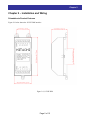
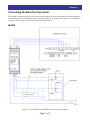
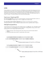
115VIF-DIN
115 VAC Input Interface Board
Instruction & Software Manual
For Crane & Hoist Pendant Applications
• WJ200 Series
• SJ700 Series
NOTE: REFER ALSO TO WJ200 OR SJ700 SERIES INSTRUCTION MANUAL
Manual Number: HAL1055D
January 2013
After reading this manual,
keep it handy for future reference.
Hitachi America, Ltd.
Chapter 1
Table of Contents
Table of Contents................................................................................................................... 2
Chapter 1 – General Description .......................................................................................... 3
Chapter 2 – Installation and Wiring ...................................................................................... 5
Chapter 3 – Configuring the Inverter ................................................................................... 9
Chapter 4 – Operation ..........................................................................................................11
Index ..................................................................................................................................... 14
Document History
January 2013 is the first edition.
Page 2 of 15
Chapter 1
Chapter 1 – General Description
The 115VIF-DIN is an interface board is used to translate 115 VAC control signals – from crane
and hoist operator pendant stations – to the 24 VDC logical input signals required by the WJ200
or SJ700 series of Hitachi inverters.
The board provides optical isolation between the 115 VAC pendant voltages and the inverter
control inputs. The necessary logic functions to perform application-specific crane and hoist
functions are not embedded on the interface board.
Before using this product, please read this manual and the inverter manual, and be sure to follow all safety
precautions noted therein. After unpacking the 115VIF-DIN board, carefully inspect it for any defect or damage.
115VIF-DIN Carton Contents
(1) 115VIF-DIN Interface Board
WARRANTY
The warranty period under normal installation and handling conditions shall be eighteen (18) months
from the date of purchase, or twelve (12) months from the date of installation, whichever occurs first.
The warranty shall cover repair or replacement, at Hitachi’s sole discretion, of the 115VIF-DIN
interface board.
Service in the following cases, even within the warranty period, shall be to the customers account:
1. Malfunction or damage caused by misuse, modification or unauthorized repair.
2. Malfunction or damage caused by mishandling, dropping, etc., after delivery.
3. Malfunction or damage caused by fire, earthquake, flood, lightning, abnormal input voltage,
contamination, or other natural disasters.
If service is required for the product at your worksite, all expenses associated with field repair are the
purchaser’s responsibility. This warranty only covers service at Hitachi designated service facilities.
If making a warranty claims in reference to the above, please contact the distributor from whom you
purchased the 115VIF-DIN, and provide the model number, purchase date, installation date, failure date
and description of damage, malfunction, or missing components.
Page 3 of 15
Chapter 1
SAFETY PRECAUTIONS
HIGH VOLTAGE: This symbol indicates high voltage. It calls your attention to items or operations
that could be dangerous to you and other persons operating this equipment. Read the message and
follow the instructions carefully.
WARNING: Indicates a potentially hazardous situation that, if not avoided, can result in serious
injury or death.
CAUTION: Indicates a potentially hazardous situation that, if not avoided, can result in minor to
moderate injury, or serious damage to the product. The situation described in the CAUTION may, if
not avoided, lead to serious results. Important safety measures are described in CAUTION (as well as
WARNING), so be sure to observe them.
HIGH VOLTAGE: Motor control equipment and electronic controllers are connected to hazardous
line voltages. When servicing drives and electronic controllers, there may be exposed components
with housings or protrusions at or above line potential. Extreme care should be taken to protect
against shock. Stand on an insulating pad and make it a habit to use only one hand when checking
components. Always work with another person in case an emergency occurs. Disconnect power
before checking controllers or performing maintenance. Be sure equipment is properly grounded.
Wear safety glasses whenever working on electronic controllers or rotating machinery.
WARNING: This equipment should be installed, adjusted, and serviced by qualified electrical
maintenance personnel familiar with the construction and operation of the equipment and the hazards
involved. Failure to observe this precaution could result in bodily injury.
WARNING: HAZARD OF ELECTRICAL SHOCK. DISCONNECT INCOMING POWER
BEFORE WORKING ON THIS CONTROL.
WARNING: Wait at least ten (10) minutes after turning OFF the input power supply before
performing maintenance or an inspection. Otherwise, there is the danger of electric shock.
WARNING: Do not install or remove the 115VIF-DIN interface board while the inverter or external
control circuits are energized. Otherwise there is the danger of electric shock and/or fire.
WARNING: Never modify the board. Otherwise, there is a danger of electric shock and/or injury.
CAUTION: Alarm connection may contain hazardous live voltage even when inverter is
disconnected. When removing the front cover for maintenance or inspection, confirm that incoming
power for alarm connection is completely disconnected.
WARNING: Do not touch the surface or terminals of the 115VIF-DIN interface board while the
inverter or external control circuit is energized; otherwise there is the danger of electric shock.
Page 4 of 15
Chapter 2
Chapter 2 – Installation and Wiring
Orientation to Product Features
Figure 2-1 below shows the 115VIF-DIN interface.
Figure 2-1, 115VIF-DIN
Page 5 of 15
Chapter 2
Installing the Interface Board
WARNING: Remove power from the inverter and wait at least five minutes before moving to the next
step. Open and remove the lower terminal cover. Confirm that the DC bus is fully discharged before
proceeding further. Also confirm that the external 115 VAC control circuits are deactivated and locked
out before proceeding. Otherwise, there is danger of electric shock, injury or death.
General
The 115VIF-DIN interface board may be used with either the WJ200 or SJ700 series of inverters. Follow the
appropriate installation instructions on the next pages for the particular model series in which you are installing
the board. The board’s 115 VAC-side wiring (from the pendant) and the corresponding AC input functions are
the same, regardless of which inverter series you are using.
AC Input Wiring – Connecting the Pendant to the 115VIF-DIN Interface Board
Connect the pendant 115 VAC input wiring to the terminals marked AC1 through AC5 on the 115VIF-DIN, with
NEU (neutral of the pendant control signals) as their common terminal. AC1 thru AC5 are connected to the
HOT side of the pendant control signals, coming from the pendant’s pushbutton contacts. The board’s AC input
terminal functions are as follows:
INPUT
AC1
(Note 1)
AC2
(Note 1)
AC3
AC4
HOIST
TRAVERSE
Up PB
Forward/Left PB
Down PB
Reverse/Right PB
nd
Increase/2 speed
Jumpered to HOT
Increase/2nd speed
Horizontal over-travel limit (NC sensor input;
open-circuit forces inverter to MIN speed)
Up over-travel photo limit (NC sensor
input; open-circuit stops/prevents UP
motion – only DOWN motion is
possible)
Jumpered to HOT
Not used/no connection
(NOTE: Neutral to be connected to AC
Common)
Not used/no connection
(Note 2)
AC5
(Note 2)
AC6
AC7
Common
Note 1:
Inputs AC1 and AC2 functions are symmetrical with respect to direction in traverse applications. In hoist applications, however, AC1 must be
used for UP and AC2 must be used for DOWN.
Note 2:
AC4 and AC5 inputs are intended to be used with over-travel limit sensors. These are secondary safeties, over and above N.C. limit switches
that would be wired in series with the AC1 and AC2 pendant inputs. They are “fail-safe” inputs, for use with N.C. type sensors. In this way, a
cut wire will have the same effect (inhibited of motion) as a sensor being triggered.
Page 6 of 15
Chapter 2
Connecting the Board to the Inverter
The method of connection of the 115VIF to the inverter depends on the inverter model. Refer to the appropriate
section below for the inverter model you have. If using for traverse application, AC1 and AC2 are symmetrical
in purpose. Please jumper AC4 and AC5 for non-hoist applications.
WJ200
Figure 2-3, 115VIF-DIN wired to WJ200 Inverter inputs with pendant
Page 7 of 15
Chapter 2
SJ700
When installed for use with an SJ700 inverter, the 115VIF-DIN must be mounted within the panel and in close
proximity to the inverter. Please connect wiring leads (20 AWG) pigtail leads from the 115VIF-DIN to the I/O
terminal strip of the SJ700 inverter. Connect the leads one by one to intelligent input terminals on the inverter
following the same numeration coding as labeled and similarly shown on the 115VIF-DIN interface label, see
Figure 2-3 on page 7. Also the FW must be used to activate the EzSQ program.
Open-Loop vs. Closed-Loop SJ700
For open-loop applications: the UP (blue) wire from the pigtail is connected to the FW terminal. In this case
there is no connection to intelligent input 1, which is configured for no function [NO].
For closed-loop (encoder feedback) applications: the UP (blue) wire from the pigtail is connected to
intelligent input terminal 1, which is configured for [MI1] function. Refer to parameter tables in Chapter 3.
Sinking/Sourcing Input Set-up
On the SJ700, the factory default setting for the intelligent inputs is for sinking logic. The 115VIF-DIN interface
requires the inputs be set for sourcing logic for proper operation. To change the logic setting, locate the small
metal jumper bar on the intelligent input terminal strip. Then:
1) Remove the jumper from its default position (shown below) between the P24 terminal and PLC
terminal.
2) Reinstall the jumper between the PLC terminal and the CM1 terminal
(1) M3 x 8 mm
screw
Page 8 of 15
Program Flowchart and Index
Chapter 3 – Configuring the Inverter
The configuration of inverter parameters will depend on the specific functionality and performance required for
your application. The basic functionality of the board is designed to interface with a two pushbutton,
two-position (two-speed) momentary contact type pendant commonly used for crane and hoist applications. This
is the basis for the descriptions of the functions of the board presented in this manual. The setup in the table
below will result in infinitely variable speeds between the programmed MIN and MAX speeds. The defined
functions of the pushbuttons are as follows:
UP
DOWN
UP, first detent: UP – accelerate to minimum speed
UP, second detent: UP – increase speed while held, up to MAX speed (or go to second speed, see page 11)
DOWN, first detent: DOWN – accelerate to minimum speed (RESET fault when inverter is
STOPPED and in a fault state)
DOWN, second detent: DOWN – increase speed, up to MAX speed (or go to second speed, see page 11)
Pushing either the UP or DOWN pushbutton to the first position causes the inverter to go to the minimum
configured speed in that direction. Pushing that button further to its second position will cause speed to increase
in that direction. Releasing back to first position will hold that last speed. Releasing the pushbutton all the way
will cause the inverter to come to a stop. If that button is re-pressed to the first position before stop is reached,
that speed will be maintained. In order to achieve this basic functionality, the installation of the EzSQ C&H
program must be downloaded to the inverter through the use of Hitachi ProDriveNext software. The software is
available to download from our company website.
This program also will require a change in parameters that differ from factory default values, as described in the
following table. The application will also write to these parameters as needed.
Parameter
Code
Function
Setting
F002
Acceleration Time
Note 1
F003
A001
A002
A004
P120
Deceleration
Time
Frequency
Command
Run Command
Maximum
Frequency
Upper Frequency
Limit
P110
Lower Frequency
Limit
B091
Stop Mode
Selection
C001
Terminal 1
Function
Note 1
Comment
Set a value between 1 and 3600 seconds, depending on application. If P031
is set to 03, acceleration is controlled by EzSQ. This is field adjustable.
Set a value between 1 and 3600 seconds, depending on application. If P031
is set to 03, deceleration will be controlled by EzSQ. This is field adjustable.
07
Tells the inverter to read speed reference from EzSQ program. See note 3.
01
Tells the inverter to take the RUN command from the control terminals.
Depending on the motor limits and application requirements, set the
appropriate value, (Must be equal or greater than P120 parameter)
Note 1
Note 1
Usually the same value as A004. See note 3. This is field adjustable.
00
Lowest speed for continuous operation (MIN speed), usually 6 to 10 Hz or
so. This is the speed that will be commanded at the first pushbutton position.
See note 3. This is field adjustable.
For Non-Load Brake Hoist, or for traverse applications: 00 (factory default)
01
For Load Brake Hoist applications: 01 (free-run or coast to stop)
Note 1
56
WJ200 = [MI1]. See note 3.
no
SJ700 Open Loop = [NO] No function
56
SJ700 Closed Loop = [MI1]. See note 3.
Page 9 of 15
Program Flowchart and Index
C002
C003
C004
C005
C006
C007
C008
C011 thru
C016[DN]
Terminal 2
Function
Terminal 3
Function
Terminal 4
Function
Terminal 5
Function
Terminal 6
Function
Terminal 7
Function
Terminal 8
Function
Terminal Active
State
01
SJ700 Open Loop = [RV] Reverse run
57
WJ200 & SJ700 Closed Loop = [MI2]. See note 3.
58
EzSQ input 2
59
EzSQ input. Horizontal over-travel limit. = [MI4]. See note 3.
60
EzSQ input. N.C. from hoist UP limit. =[MI5]. See note 3.
18
[RS] Reset on WJ200.
62
EzSQ input. This input switches the software from 2 speeds to infinite speed
control. =[MI7]. See note 3.
no
[NO] No Function – Available on SJ700 only
00
All inputs should be configured for N.O. (normally open = active on)
operation (Note 2)
nd
speed / increase speed. = [MI3]. See note 3.
C102
Reset function
selection
2
Makes the RESET [RS] input terminal (input 6) active only when the inverter
is in the fault state. In this way, the pendant DOWN pushbutton can also
used to reset an inverter fault. See note 3.
P031
Accel / Decel
Option
03
This allows the EzSQ software to determine the programmed acceleration
and deceleration rates. If F002 and F003 are used, set to 00.
Note 1: Actual setting is dependent on inverter capacity and your design requirements. Software controlled when applicable.
Note 2: C011 to C018 in the case of SJ700 series
Note 3: The parameters initial values are set by activating the EzSQ program.
Other Required Settings
The following were previously noted in the Installation and Wiring chapter, but are important and bear
repeating. Make sure the following steps were performed.
WJ200
Please confirm that the jumper bar/wire is between PLC and L, as explained in Chapter 2, for proper operation
of the 115VIF-DIN interface board.
SJ700
The SR/SK DIP switch in close proximity to the terminal connection block must be in default “SR” position.
Confirm that the source/sink jumper bar is between PLC and CM1, as explained in Chapter 2. Confirm the
correct setting of B091 for load-brake vs. non-load-brake applications. Please verify the SJ700 parameter A017
is set to 01 and a jumper or closed contact is wired between P24 and FW to enable to program to run.
Software Use Set Up
The EzSQ program needs to be successfully downloaded to the inverter and activated through the A017
selection to 02. The software is designed to utilize the intelligent logic inputs to determine the rotation direction,
and speed of the motor based on the various contact states as presented to the inverter through the 115VIF-DIN.
Please remember to test the software with a disconnected load, and perform all activities and take all proper
precautions before activating the software or inverter. Safety in operation should be the primary concern.
Please visit our website at http://www.hitachi-america.us/ice/inverters/ for the ProDriveNext software and
suggestive use crane and hoist program in our application notes section.
Page 10 of 15
Program Flowchart and Index
Two-Speed Operation
The inverter can easily be configured for two-speed operation or infinitely variable speed operation by using the
following parameter settings in lieu of or in addition to those in the table above:
Parameter
Code
Function
Setting
A017
EzSQ
Operation
00, 01,
02
C017
Terminal 7
Status
00, 01
Comment
00 deactivates the C&H EZSQ software. 01 will activate the software
when the terminal FW is active on SJ700 units. 02 will make EZSQ
active at all times on WJ200 only.
00 is used for 2 speed operation. 01 is for infinite variable speed
control
The 2 speed control selection for the inverter is based on parameter C017, (C017=00) is applicable to
pendant stations with two-position pushbuttons, and can be applied to hoist and/or traverse axes. With
the above settings, at the first pushbutton position, the inverter will ramp to MIN speed as defined in
parameter P110 and hold. On depressing the button to the second pushbutton position, the inverter will
accelerate to the P120 parameter set speed and hold. Releasing the pushbutton back to the first position
will cause the inverter to decelerate back to the MIN speed as set in P110 and hold. Releasing the
pushbutton will cause the inverter to come to a stop.
Infinite Variable Speed Operation
Normal Operation
Once the inverter parameters are set as described in Chapter 3, you are ready to verify proper operation. It is
recommended to first test the system with the motor mechanically disconnected from the crane or hoist, to
ensure that any unexpected behavior will not damage the equipment or risk injury.
Energize the inverter and the pendant or other external control circuit power supplies, and press the pushbutton
connected to input terminal AC1. This is the UP hoist or FORWARD/LEFT traverse input. Observe motor
rotation. If direction is NOT correct, remove power from the inverter and wait 10 minutes for the capacitors to
discharge. Then interchange any two motor leads. Restore power and repeat the initial test. Direction should
now be correct. Once the corresponding AC1 pushbutton pressed to the first detent, the motor will accelerate in
the forward direction, (corresponding to UP motion for the hoist), to the frequency set in P110 (MIN speed), and
remain at that speed, unless:
• The pushbutton is released, in which case the motor will come to a stop, OR
• Ramp to a higher speed, while pushbutton is pushed to the second detent (AC3). If AC1 or AC 2 is
maintained, and AC3 is subsequently released, the speed attained at that time will be maintained.
• Releasing AC1 or AC 2 at this point will cause the motor speed to ramp down or stop.
• If AC1 or AC 2 remains off long enough, the motor will come to a stop.
• If AC1 is re-activated at any speed above the MIN speed, then that speed will be maintained for the
duration. If AC1 is reactivated at a speed below the MIN speed, the motor will accelerate to MIN speed
and maintain that speed until one of the above events occurs.
The function of AC2 pushbutton is the same as the AC1 pushbutton, with the exception that rotation direction is
reversed (corresponding to DOWN operation for a hoist).
Page 11 of 15
Program Flowchart and Index
Troubleshooting
Symptom
Inverter will not accelerate beyond minimum speed
Inverter will only turn the motor in one direction
Remedy
Input AC4 is not jumpered to HOT
Input AC5 is not jumpered to HOT
Note: For other troubleshooting tips, refer to Chapter 6 of the pertinent inverter Instruction Manual
Electrical Specifications
The board does require power for the AC inputs, however, the outputs are powered from the inverter’s internal
24 Vdc power supply, drawing approximately 21 mA. The AC inputs are optically isolated, and draw
approximately 2 mA each. The outputs to the inverter have a 100 mA maximum capacity.
EzSQ Program Flowchart Diagram
Page 12 of 15
Program Flowchart and Index
Functionality Table (based on contact status)
Up (AC1)
Open
Closed
Closed
Open
Open
Closed
Closed
Open
Open
Closed
Closed
Open
Open
Closed
Closed
Closed
Closed
Closed
Closed
Up / Hi Speed
(AC1 &AC3)
Open
Open
Closed
Open
Open
Open
Closed
Open
Open
Open
Closed
Open
Open
Open
Closed
Closed
Open
Closed
Closed
Down (AC2)
Open
Open
Open
Closed
Closed
Open
Open
Closed
Closed
Open
Open
Closed
Closed
Closed
Closed
Closed
Closed
Closed
Closed
Down / Hi Speed
Side Limit (AC4)
(AC2 & AC3)
Open
Closed
Open
Closed
Open
Closed
Open
Closed
Closed
Closed
Open
Open
Open
Open
Open
Open
Closed
Open
Open
Closed
Open
Closed
Open
Closed
Closed
Closed
Open
Closed
Closed
Closed
Open
Closed
Closed
Closed
Closed
Open
Open
Closed
Page 13 of 15
Up Limit (AC5)
Motor Output
Closed
Closed
Closed
Closed
Closed
Closed
Closed
Closed
Closed
Open
Open
Open
Open
Closed
Closed
Closed
Closed
Closed
Open
No motor output
Up at Min. speed or last speed
Up, accelerates to Max speed
Down at Min. or last speed
Down, accelerates to Max. speed
Up, only at Min. speed
Up, only at Min. speed
Down, only at Min. speed
Down, only at Min. speed
No motor output
No motor output
Down at Min. or last speed
Down, accelerates to Max. speed
No motor output
No motor output
No motor output
No motor output
No motor output
No motor output
Program Flowchart and Index
Index
A
M
AC Input Wiring · 7
MIN speed · 11
C
O
Closed-loop · 8
Configuration, inverter · 9
Contents, carton · 3
Open-loop · 8
Operation · 11
P
D
Pendant · 7, 9
DIP switch · 10
R
E
Electrical Specifications · 12
Reset, fault · 10
Rotation, direction of · 11
F
S
Faults, resetting · 10
Functionality table · 9
Safety Precautions · 4, 6, 10
Sensor, (N.C limits)over-travel · 7
Sinking/sourcing · 8
WJ200 · 7, 10
SJ700 · 8
Software State Diagram · 12
Speed, minimum · 11
SR/SK · 10
H
Hoist · 6, 11
I
Input functions · 11
Installing · 6
Inverter parameters · 9
T
J
Traverse · 6
Trip reset · 11
Troubleshooting · 12
Two-speed operation · 11
Jumper bar · 8
W
L
Warranty · 3
Wiring · 6
Layout, physical dimensions · 5
Load-brake ·10
Page 14 of 15
Hitachi America, Ltd.
Tarrytown, NY 10591
© 2009
http://www.hitachi-america.us/inverters
January, 2013
HAL1055D