1
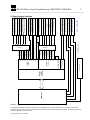
PAT America, Inc.
Rheinmetall Elektronik
DS350 G BOOM CONTROL
for
GROVE CRANE
RT865 BXL, TMS 870, TTS 870
WITH 5 SECTION BOOM
TROUBLESHOOTING MANUAL
031-300-190-039 Rev. B 04/30/99
DS 350 G Boom Control Troubleshooting- TMS/TTS870 / RT865 BXL
Notice
The information in this document is subject
to change without notice.
PAT makes no warranty of any kind with regard
to this material, including, but not limited to,
the implied warranties of merchantability
and fitness for a particular purpose.
PAT shall not be liable for errors contained herein
or for incidental or consequential damages in
connection with the furnishing, performance
or use of this manual.
This document contains proprietary information
which is protected by copyright. All rights are
reserved. No part of this document may be
photocopied, reproduced, or translated to
another language without prior consent of PAT.
031-300-190-039 Rev. B 04/30/99
DS 350 G Boom Control Troubleshooting- TMS/TTS870 / RT865 BXL
TABLE OF CONTENTS
Section
1
2
3
4
5
6
7
8
9.1
9.2
9.3
9.4
10.1
10.2
11.1
11.2
12
13
14
15
16
17
18.1
18.2
Content
General Information
Reference Material
Warnings
Service and Maintenance
Boom Control Interface
Boom Sequence
Boom Control Flow
Ramping
DS 350 G - Boom Components and Setup
Length Transducer Adjustment
DS 350 G - Superstructure Components - TMS/ TTS 870
DS 350 G - Superstructure Components - RT 865 BXL
DS350 G LMI Central unit (751) - TMS/ TTS 870 & RT 865 BXL
LMI Terminal board - TMS/ TTS 870 & RT 865 BXL
Wiring Schematic - TMS/ TTS 870
Wiring Schematic - RT 865 BXL
Boom Length Percentage Error
Main Boom Length Error
Inner Mid Length Error
Center Mid Length Error
No Extend or Retract Function in Automode
Out of Sequence Warning
Additional Error Codes - Operational
Additional Error Codes -System
031-300-190-039 Rev. B 4/30/99
Page
1
1
1
2
3
9
10
12
13
15
16
17
18
19
20
25
29
37
43
49
55
57
62
63
DS 350 G Boom Control Troubleshooting- TMS/TTS870 / RT865 BXL
1
1. General Information
The DS 350 load moment indicator (LMI) with boom control extension is designed to aid the
crane operator through the crane operations. The DS 350 with boom control extension is not,
and shall not, be a substitute for good operator judgment, experience and use of accepted
safe crane operating procedure.
2. Reference Material
Parts & Installation Manual:
Crane Model
TMS/ TTS 870
RT 865 BXL
PAT- Part number
031-300-150-662
031-300-150-659
Grove- Part number
9-333-103129
9-333-103-206
Operator’s Handbook:
PAT - Part number
50\350\19_1319e.doc
3. Warnings
The DS 350 load moment indicator (LMI) with boom control extension is an operational aid
that warns the crane operator when he approaches an overload condition, a two block
condition and an out of boom sequence condition. The boom control extension controls the
sequence of the boom during operation. It still remains the operator’s responsibility to verify
the operation and to select the correct mode during crane operations.
The manual mode is a rigging mode. Lifting loads with manual mode programmed is
prohibited.
Should an out of sequence condition occur, the crane operator is responsible to select
manual mode to return the sections into sequence before continuing the lift.
The responsibility for safe crane operation shall remain with the crane operator who shall
ensure that all warnings and instructions supplied are fully understood and observed.
Prior to operating the crane, the operator must carefully and thoroughly read and understand
the information provided by the crane and load moment indicator manufacturer.
Proper functioning depends upon proper daily inspection and observance of the operating
instructions provided with the crane and load moment indicator.
031-300-190-039 Rev. B 4/30/99
DS 350 G Boom Control Troubleshooting- TMS/TTS870 / RT865 BXL
2
4. Service and Maintenance
Daily maintenance of the load moment indicator consists of inspecting:
1. The electrical wiring connecting the various parts of the system.
If electrical wiring is damaged, it shall be replaced immediately.
2. If the insulation is worn on the length sensor cable or cable guides are damaged, these
parts shall be replaced.
3. Check the anti two-block limit switches for freedom of movement.
4. The cable reel shall be under tension to operate properly.
5. Check the pressure transducers at the hoist cylinder(s) and the connecting hoses for oil
leakage.
Other than correcting the problems identified in the Malfunctions Table and replacing faulty
mechanical parts and cables, no other repairs shall be performed by non expert personnel.
031-300-190-039 Rev. B 4/30/99
LMI Circuit
Boom
control
circuit
031-300-190-039 Rev. B 4/30/99
Prop.
* = RT 865BXL only
OM 2- way valve
CM 2- way valve
Proportional
output / extend
Proportional
output / retract
Tele out of
sequence
Rod side dump
valve
IM 2- way valve
Area def. switch *
Center mid retracted & 0%
Inner mid 0%
Inner mid retracted
OM/Fly retracted & 0%
Front O/R overloaded
Auto mode A *
House lock engaged
Auto mode on
Crane interface
connector
LMI Console
Analog input
Analog output
K5
K7
K6
K5
K5
K4
K3
K2
DI 11
DI 6
DI 5
DI 4
DI 9
Boom extend
Boom retract
Crane interface
connector
Relays
output
Digital
Input
DI 8
DI 7
DI 3
DI 2
DI 1
870 - LMI (751)
Piston pressure transducer
Rod pressure transducer
Main boom angle sensor
Main boom length sensor
Center mid length sensor
Inner mid length sensor
2- way valves (outer mid)
2- way valves (center mid)
pressure reducing valve/
retract
pressure reducing valve/
extend
Out of sequence warning light
Rod side dump valve
2- way valves (inner mid)
Prox.switch on IM section
Prox.switch on base section
Prox.switch on base section
Prox.switch on CM section
Front O/R pressure switch
Automode switch in cabin
P-switch retract pilot pressure
P-switch extend pilot pressure
House lock switch (EEC units) *
Automode A selector switch
DS 350 G Boom Control Troubleshooting- TMS/TTS870 / RT865 BXL
3
5. Boom Control Interface
Drawing 1.
PAT Equipment Corporation reserves proprietary rights to this drawing and to the data shown there on. The drawing and data are
confidential and are not to be used or reproduced without the written consent of PAT Equipment Corporation. This drawing is subject to
technical modification without prior notice.
DS 350 G Boom Control Troubleshooting- TMS/TTS870 / RT865 BXL
4
Auto mode / Manual mode:
The operator selects auto mode or manual mode using the rocker switch in the dash board.
Auto mode is the working mode and manual mode is used for rigging or sequencing purpose
only.
Pilot pressure switch signal / Analog output signal:
Two pressure switches in the pilot pressure circuit are used to distinguish between boom
extend or boom retract. The two circuits are wired through the crane interface connector into
the DS 350 G central unit.
When the operator extends the boom, the pressure switch signal at central unit terminal
A101-X1/38 changes from 0V to +24V. The boom control logic allows electrical current to
flow to the extend pressure reducing valve coil. The minimum current equals 0 mA with the
control in neutral position. The maximum current output equals 800 mA.
To measure the coil current while extending, remove wire #20from central unit terminal
A101-X1/63. Connect the Amp-meter in series with wire #20 to terminal X1/63.
When the operator retracts the boom, the pressure switch signal at central unit terminal
A101-X1/40 changes from 0V to +24V. The boom control logic allows electrical current to
flow to the retract pressure reducing valve coil. The minimum current equals 0 mA with the
control in neutral position. The maximum current output equals 800 mA.
To measure the coil current while retracting, remove wire #21 from central unit terminal
A101-X1/64. Connect the Amp-meter in series with wire #21 to terminal X1/64.
031-300-190-039 Rev. B 4/30/99
DS 350 G Boom Control Troubleshooting- TMS/TTS870 / RT865 BXL
5
Length sensors:
Three length sensors are mounted to the boom base section to measure the overall length,
the inner mid section length and the center mid section length. The software utilizes the
signals to calculate the outer mid and fly section length.
Disengage the boom stop to retract the boom completely.
With retracted main boom the overall boom length signal is -500 mV (A101-X1/10). Use the
test pin MP 15 (AGND) or terminal A101-X1/8 (AGND) for reference ground. Disengage the
boom stop to retract the boom completely.
With retracted main boom the inner mid section length signal is -500 mV (A101-X1/24). Use
the test pin MP 15 (AGND) or terminal A101-X1/8 (AGND) for reference ground.
With retracted main boom the center mid section length signal is -500 mV (A101-X1/73). Use
the test pin MP 15 (AGND) or terminal A101-X1/8 (AGND) for reference ground.
Keep the cable on the length transducer drum spooled properly. A poorly spooled cable may causes the boom to
become out of sequence. If the boom becomes out of sequence, select manual mode and correct the length by
operating individual sections. Once the sections are sequenced again the operator may return to the automode.
Refer to section 9.1 for boom components installation and set up.
Inner mid retract and % reset switch:
The reset- proximity switch on the base section provides a (+24V) signal to central unit
terminal A 104 X1/80 when the inner mid section is retracted against the boom stop. The
signal resets the inner mid percentage to 1%.
The retract- proximity switch on the base section provides a (+24V) signal to central unit
terminal A 104 X1/78 when the inner mid section is fully retracted (disengage the boom stop).
031-300-190-039 Rev. B 4/30/99
DS 350 G Boom Control Troubleshooting- TMS/TTS870 / RT865 BXL
6
Center mid retract and % reset switch:
The proximity switch on the inner mid section provides a (+24V) signal to central unit terminal
A 114 X1/9 when the center mid section is fully retracted. The signal resets the center mid
percentage to 0%.
Refer to Parts & Installation Manual and follow the installation instructions for switch and target adjustment.
Outer mid/ fly retract and % reset switch:
The proximity switch on the center mid section provides a (+24V) signal to central unit
terminal A 114 X1/76 when the outer mid and fly section is fully retracted. The signal resets
the outer mid/ fly percentage to 0%.
Refer to Parts & Installation Manual and follow the installation instructions for switch and target adjustment.
System inputs:
DI #
Description
1 MB
Pressure switch - boom extend
GND
Pressure switch -boom retract
GND
Automode switched on
GND
Outer mid/ fly retract and % switch
GND
Inner mid retract switch
GND
Inner mid % reset switch
GND
House lock engaged (RT 865 BXL-- Europe) *
GND
Automode A = on; Automode B = off *
GND
+ Ub (24V)
Front outrigger overload (GND)
Area def. switch (RT 865 BXL) *
GND
Center mid retract and % reset switch
GND
2 MB
3 MB
4 MB
5 MB
6 MB
1 EX
2 EX
3 EX
4 EX
5 EX
Note: MB = main board
EX = extension board
031-300-190-039 Rev. B 4/30/99
Central Unit
Terminal
A104 - X1/38
A104 - X1/37
A104 - X1/40
A104 - X1/39
A104 - X1/42
A104 - X1/41
A104 - X1/76
A104 - X1/75
A104 - X1/78
A104 - X1/77
A104 - X1/80
A104 - X1/79
A114 - X1/1
A114 - X1/2
A114 - X1/3
A114 - X1/4
A114 - X1/5
A114 - X1/6
A114 - X1/7
A114 - X1/8
A114 - X1/9
A114 - X1/10
* = RT 865 BXL only
Signal
(DI=on)
+24V
0V
+24V
0V
+24V
0V
+24V
0V
+24V
0V
+24V
0V
+24V
0V
+24V
0V
+24V
0V
+24V
0V
+24V
0V
7
DS 350 G Boom Control Troubleshooting- TMS/TTS870 / RT865 BXL
Output for two- way valves:
A pair of two- way valves controls the oil to each tele- cylinder. The relay output K2, K6, K7
operates the pair of two- way valves in automode. The valve need to be de-energized to
operate the particular cylinder. The valves for the sections that are not selected are powered
to prevent movement of the other cylinders.
Mode
Relay K2
[V]
A104-X1/54
0
24
24
IM 2 way
valves
Manual IM
Manual CM
Manual OM
Error (Auto)
Neutral (Auto)
Auto IM
Auto CM
Auto OM
CM 2 way
valves
0
1
1
Relay K6
[V]
A104-X1/66
24
0
24
OM 2 way
valves
1
0
1
Relay K7
[V]
A104-X1/69
24
24
0
0
0
0
0*
1*
1*
0
0
0
1*
0*
1*
0
0
0
1*
1*
0*
24
24
1
1
24
24
1
1
24
24
1
1
1
1
0
Note: * = powered directly from the section selector switch in the cabin.
Relay outputs:
Relay
Fuse
K1
F2
K2
F3
K3
F4
K4
F5
K5
K5
K5
K6
K6
K7
F6
F8
K8
K9
K10
none
none
external
F7
031-300-190-039 Rev. B 4/30/99
Description
not used
not used
Inner mid two way- valves
GND
Rod side dump valve
GND
Tele out of sequence - Warning light in cabin
GND
Signal from analog output board
Directs the analog signal to the extend valve
Directs the analog signal to the retract valve
Center mid two way- valves
GND
Outer mid two way- valves
GND
Internal LMI use (overload, error)
Internal LMI use (A2B)
Motion cut (Bosch relay)
Central Unit
Terminal
A104 - X1/54
A104 - X1/3
A104 - X1/57
A104 - X1/3
A104 - X1/61
A104 - X1/3
A104 - X1/62
A104 - X1/63
A104 - X1/64
A104 - X1/66
A104 - X1/3
A104 - X1/69
A104 - X1/3
A104 - X1/44
A104 - X1/46
A104 - X1/48
Signal
+24V
0V
+24V
0V
+24V
0V
0-800mA
0-800mA
0-800mA
+24V
0V
+ 24V
0V
+ 24V
+ 24V
+ 24V
DS 350 G Boom Control Troubleshooting- TMS/TTS870 / RT865 BXL
8
Rod side dump valve:
Relay K3 controls the rod side dump valve. The valve dumps the rod side pressure when the
controller is in neutral position and during the time the section stops while changing over to
another section.
Controller
Extend on
Retract on
Neutral
Retracted/ retract on
031-300-190-039 Rev. B 4/30/99
Relay K3
A101 x1/ 57
0V
0V
+24V
+24V
9
DS 350 G Boom Control Troubleshooting- TMS/TTS870 / RT865 BXL
6. Boom Sequence
Main Boom:
Mode
Auto B
Auto B
Auto B
Auto B
Auto B
Auto B
Auto B
Auto B
IM %
0
50
50
75
75
100
100
100
CM %
0
0
50
50
75
75
100
100
OM %
0
0
0
0
0
0
0
100
FLY %
0
0
0
0
0
0
0
100
Mode
Auto A *
Auto A *
Auto A *
Auto A *
IM %
0
0
0
100
CM %
0
100
100
100
OM %
0
0
100
100
FLY %
0
0
100
100
OM %
0
0
0
100
FLY %
0
0
0
100
*= Mode A not available on RT 865 BXL
Extensions:
Mode
Auto
Auto
Auto
Auto
031-300-190-039 Rev. B 4/30/99
IM %
0
100
100
100
CM %
0
0
100
100
DS 350 G Boom Control Troubleshooting- TMS/TTS870 / RT865 BXL
7. Boom Control Flow
Operator moves
controller to extend or
retract position.
Directional pressure
switch transmits signal
to B.C.S.
B.C.S. checks input for
Automode.
off
Operation in manual
mode.
on
B.C.S. checks input for
A mode or B mode.
B.C.S. checks the
retract and % reset
switch and boom
length. Refer to section
6 for sequencing
information.
continue on next
page
Drawing 2a.
031-300-190-039 Rev. B 4/30/99
Console displays
length and % of each
section.
correct
incorrect
B.C.S. defaults into a
rigging mode, console
displays error code or
dashboard warning
light indicates "out of
sequence". Refer to
section 16 for BCS
error codes
10
DS 350 G Boom Control Troubleshooting- TMS/TTS870 / RT865 BXL
Continuation
The B.C.S. relays K2,
K6, K7 provide power
to the 2 way valves
allowing oil flow to the
selected cylinder.
The B.C.S. relay K3
controls the rod side
dump valve. Refer to
section 5.
The B.C.S. analog
output signal opens the
pressure reducing
valves (proportional
valves).
While estending and
retracting the B.C.S.
monitors each section
length.
incorrect
correct
The B.C.S. controls the
speed and sequence of each
boom section.
Drawing 2b.
031-300-190-039 Rev. B 4/30/99
Out of sequence warning and lock
out.Operate in manual mode to resequence the boom. Reference
section 9.1 for boom components
and setup.
11
12
DS 350 G Boom Control Troubleshooting- TMS/TTS870 / RT865 BXL
8. Ramping
Ramp
Value
Max. Ramp
Value
Ramp down
Max. Ramp
Value
Ramp up
Boom
Section A
-e.g. IM-
Min. Ramp
Value
Change
Over
Drawing 3.
Boom
Section B
-e.g. CM-
Boom
Length
Ramp value:
A hex value in the software which determines the output current to the proportional valve.
Max. ramp value: The maximum hex value (hex 255) equals to 800 mA valve (pressure reducing valve). This
current is required to open the valve for maximum tele speed.
Min. ramp value: The minimum hex value that is required to move a section in the ramping area. These values
may differ for each ramping area.
Change over:
The previous section comes to a complete stop and the next section ramps up (accelerates
speed).
IM:
CM:
OM/Fly:
Inner Mid Section
Center Mid Section
Outer Mid Section & Fly
PAT Equipment Corporation reserves proprietary rights to this drawing and to the data shown there on. The drawing and data are
confidential and are not to be used or reproduced without the written consent of PAT Equipment Corporation. This drawing is subject to
technical modification without prior notice.
031-300-190-039 Rev. B 4/30/99
DS 350 G Boom Control Troubleshooting- TMS/TTS870 / RT865 BXL
13
9.1 DS 350 G - Boom Components and Setup
4
Inner mid length
sensor LG 221
8/9
Inner mid %
reset switch
Center mid
length and
angle sensor
LWG 221
3
7
4
7
Center mid
retract and %
reset switch
5
1
2
Inner mid
retract switch
Overall boom
length sensor
LG 208
Outer mid
retract and %
reset switch
Drawing 4.
1. Pre-tension the cable reel spring by rotating drum (16) revolution counterclockwise. If replacing the LG 208
un-spool the length cable and secure to bushing on the boom nose as noted in the installation drawing. Zero
the length potentiometer as described on page 18.
2. Pre-tension the cable reel spring by rotating drum (35) revolution counterclockwise. If replacing the LG 221
un-spool the length cable and secure to bushing on the boom nose as noted in the installation drawing. Zero
the length potentiometer as described on page 18.
3. Pre-tension the cable reel spring by rotating drum (30) revolution counterclockwise. If replacing the LWG 221
un-spool the length cable and secure to bushing on the boom nose as noted in the installation drawing. Zero
the length potentiometer as described on page 18.
4. Run cable through the cable guides. Remove 1/4-20 nuts on bottom of cable guide, insert cable guide
screws through existing angle bracket and secure in place with 1/4-20 nuts removed previously.
5. Center line of cable must be aligned with center line of cable drum. See partial top view.
PAT Equipment Corporation reserves proprietary rights to this drawing and to the data shown there on. The drawing and data are
confidential and are not to be used or reproduced without the written consent of PAT Equipment Corporation. This drawing is subject to
technical modification without prior notice.
031-300-190-039 Rev. B 4/30/99
DS 350 G Boom Control Troubleshooting- TMS/TTS870 / RT865 BXL
14
1. Place tie wrap, 120 degree apart around the bushing. Wrap cable (8-10) revolutions over the tie wraps
starting from the outside and working inward. Allow ample cable to reach the junction box. Secure with (2)
additional tie wraps. See page 17.
2. Check proximity switch installation (0.44 inch from target) when boom sections are fully retracted.
3. This target is only installed if the boom is equipped with a boom extension stop block.
4. Check this proximity switch installation (0.13 inch from target) when boom sections are fully retracted.
This proximity
switch is used to
sense the center
mid section fully
retracted.
This proximity
switch is used to
reset the inner mid
percentage.
0.44”
0.44”
Partial top view
0.44”
3.94”
1.34”
6
To be aligned
with center line
of cable reel
drum.
This proximity switch
is used to sense the
inner mid section fully
retracted.
Drawing 5.
PAT Equipment Corporation reserves proprietary rights to this drawing and to the data shown there on. The drawing and data are
confidential and are not to be used or reproduced without the written consent of PAT Equipment Corporation. This drawing is subject to
technical modification without prior notice.
031-300-190-039 Rev. B 4/30/99
DS 350 G Boom Control Troubleshooting- TMS/TTS870 / RT865 BXL
15
9.2 Length Transducer Adjustment
Drawing 6.
PAT Equipment Corporation reserves proprietary rights to this drawing and to the data shown there on. The drawing and data are
confidential and are not to be used or reproduced without the written consent of PAT Equipment Corporation. This drawing is subject to
technical modification without prior notice.
031-300-190-039 Rev. B 4/30/99
DS 350 G Boom Control Troubleshooting- TMS/TTS870 / RT865 BXL
16
9.3 DS 350 G Superstructure Components - TMS/TTS 870
Drawing 7.
PAT Equipment Corporation reserves proprietary rights to this drawing and to the data shown there on. The drawing and data are
confidential and are not to be used or reproduced without the written consent of PAT Equipment Corporation. This drawing is subject to
technical modification without prior notice.
031-300-190-039 Rev. B 4/30/99
DS 350 G Boom Control Troubleshooting- TMS/TTS870 / RT865 BXL
17
9.4 DS 350 G Superstructure Components - RT 865 BXL
Drawing 8.
PAT Equipment Corporation reserves proprietary rights to this drawing and to the data shown there on. The drawing and data are
confidential and are not to be used or reproduced without the written consent of PAT Equipment Corporation. This drawing is subject to
technical modification without prior notice.
031-300-190-039 Rev. B 4/30/99
DS 350 G Boom Control Troubleshooting- TMS/TTS870 / RT865 BXL
18
10.1 DS 350 G LMI central unit (751) - TMS/TTS 870 & RT 865 BXL
Diode extension
board
Real time clock (Timer board)
with e-prom sockets
Diode extension
board
Analog output
extension board
3rd wrap warning
relay board
Digital input
extension board
Decoder board
Key to open central unit
enclosure
Termial board
Drawing 9.
PAT Equipment Corporation reserves proprietary rights to this drawing and to the data shown there on. The drawing and data are
confidential and are not to be used or reproduced without the written consent of PAT Equipment Corporation. This drawing is subject to
technical modification without prior notice.
031-300-190-039 Rev. B 4/30/99
DS 350 G Boom Control Troubleshooting- TMS/TTS870 / RT865 BXL
19
10.2 LMI Terminal board - TMS 870, TTS 870 and RT 865 BXL
X1
X1
X1
F8
F7
F6
K6
F5
K7
K5
F4
X1
F3
K3
F2
K4
K2
X1
K1
K9
F1
K8
K10
X1
X1
X1
X1
Drawing 10.
PAT Equipment Corporation reserves proprietary rights to this drawing and to the data shown there on. The drawing and data are
confidential and are not to be used or reproduced without the written consent of PAT Equipment Corporation. This drawing is subject to
technical modification without prior notice.
031-300-190-039 Rev. B 4/30/99
DS 350 G Boom Control Troubleshooting- TMS/TTS870 / RT865 BXL
20
11.1 Wiring Schematic - TMS 870/ TTS 870
Drawing 11.1
PAT Equipment Corporation reserves proprietary rights to this drawing and to the data shown there on. The drawing and data are
confidential and are not to be used or reproduced without the written consent of PAT Equipment Corporation. This drawing is subject to
technical modification without prior notice.
031-300-190-039 Rev. B 4/30/99
DS 350 G Boom Control Troubleshooting- TMS/TTS870 / RT865 BXL
21
11.1 Wiring Schematic - TMS 870/ TTS 870
Drawing 11.2
PAT Equipment Corporation reserves proprietary rights to this drawing and to the data shown there on. The drawing and data are
confidential and are not to be used or reproduced without the written consent of PAT Equipment Corporation. This drawing is subject to
technical modification without prior notice.
031-300-190-039 Rev. B 4/30/99
DS 350 G Boom Control Troubleshooting- TMS/TTS870 / RT865 BXL
22
11.1 Wiring Schematic - TMS 870/ TTS 870
Drawing 11.3
PAT Equipment Corporation reserves proprietary rights to this drawing and to the data shown there on. The drawing and data are
confidential and are not to be used or reproduced without the written consent of PAT Equipment Corporation. This drawing is subject to
technical modification without prior notice.
031-300-190-039 Rev. B 4/30/99
DS 350 G Boom Control Troubleshooting- TMS/TTS870 / RT865 BXL
23
11.1 Wiring Schematic - TMS 870/ TTS 870
Drawing 11.4
PAT Equipment Corporation reserves proprietary rights to this drawing and to the data shown there on. The drawing and data are
confidential and are not to be used or reproduced without the written consent of PAT Equipment Corporation. This drawing is subject to
technical modification without prior notice.
031-300-190-039 Rev. B 4/30/99
DS 350 G Boom Control Troubleshooting- TMS/TTS870 / RT865 BXL
24
11.1 Wiring Schematic - TMS 870/ TTS 870
Drawing 11.5
PAT Equipment Corporation reserves proprietary rights to this drawing and to the data shown there on. The drawing and data are
confidential and are not to be used or reproduced without the written consent of PAT Equipment Corporation. This drawing is subject to
technical modification without prior notice.
031-300-190-039 Rev. B 4/30/99
DS 350 G Boom Control Troubleshooting- TMS/TTS870 / RT865 BXL
25
11.2 Wiring Schematic - RT 865 BXL
Drawing 12.1
PAT Equipment Corporation reserves proprietary rights to this drawing and to the data shown there on. The drawing and data are
confidential and are not to be used or reproduced without the written consent of PAT Equipment Corporation. This drawing is subject to
technical modification without prior notice.
031-300-190-039 Rev. B 4/30/99
DS 350 G Boom Control Troubleshooting- TMS/TTS870 / RT865 BXL
26
11.2 Wiring Schematic - RT 865 BXL
Drawing 12.2
PAT Equipment Corporation reserves proprietary rights to this drawing and to the data shown there on. The drawing and data are
confidential and are not to be used or reproduced without the written consent of PAT Equipment Corporation. This drawing is subject to
technical modification without prior notice.
031-300-190-039 Rev. B 4/30/99
DS 350 G Boom Control Troubleshooting- TMS/TTS870 / RT865 BXL
27
11.2 Wiring Schematic - RT 865 BXL
Drawing 12.3
PAT Equipment Corporation reserves proprietary rights to this drawing and to the data shown there on. The drawing and data are
confidential and are not to be used or reproduced without the written consent of PAT Equipment Corporation. This drawing is subject to
technical modification without prior notice.
031-300-190-039 Rev. B 4/30/99
DS 350 G Boom Control Troubleshooting- TMS/TTS870 / RT865 BXL
28
11.2 Wiring Schematic - RT 865 BXL
Optional Data Logger Connection
Drawing 12.4
PAT Equipment Corporation reserves proprietary rights to this drawing and to the data shown there on. The drawing and data are
confidential and are not to be used or reproduced without the written consent of PAT Equipment Corporation. This drawing is subject to
technical modification without prior notice.
031-300-190-039 Rev. B 4/30/99
DS 350 G Boom Control Troubleshooting- TMS/TTS870 / RT865 BXL
12. Boom Length Percentage Error
Boom length
percentage error
Keep the boom stop block
latched. Switch to Manual
Mode and retract the boom
completely.
Is the
percentage reading
(1%, 0%, 0%)?
Yes
No
The LMI does not recognize the one or
more reset switch signals. Check
proximity switch target adjustment as
per section 9.1. If damage is visible
install new switch.
Measure voltage supply to IM switch at
terminal 1or 2 (+24V) and 5 or 6 (GND)
in the junction box at the front of the
boom base. Refer to section 9.1 and11.
Continue on next page
031-300-190-039 Rev. B 4/30/99
Continue with section 13.
29
DS 350 G Boom Control Troubleshooting- TMS/TTS870 / RT865 BXL
12. Continuation
Continuation
Is the
voltage
correct?
No
Yes
Keep the inner mid section retracted.
Measure the inner mid reset switch signal
at terminal 3 (24V) and 5 (GND) in the
junction box at the front of the boom base
section. Refer to section 9.1 and 11.
Is the
voltage
correct ?
Faulty voltage supply wiring to
switch.Refer to section 11.
Replace defective cables.
No
Yes
Measure the IM reset switch signal at
terminal 5 (24V) and 9 (GND) in the length
sensor LG221. Refer to section 9.1 and 11.
Continue on next page
031-300-190-039 Rev. B 4/30/99
Defective IM reset switch.
Replace proximity switch.
30
DS 350 G Boom Control Troubleshooting- TMS/TTS870 / RT865 BXL
12. Continuation
Continuation
Is the
voltage
correct?
No
Yes
Measure the IM reset switch signal at
terminal 15 (24V) and 14 (GND) in the
boom base junction box. Refer to
section 9.1 and 11.
Is the
voltage
correct?
Faulty wiring in cable
connecting the junction box
with the length sensor. Refer to
section 11 to locate the fault.
No
Yes
Measure the IM reset switch signal at central unit
terminal A104 80 (24V) and A 101 36 (GND).
Refer to section 9.3, 10 and 11.
Continue on next page
031-300-190-039 Rev. B 4/30/99
Faulty wiring in cable connecting
the length sensor LG221 and the
boom base junction box. Refer to
section 11 to locate the fault.
31
DS 350 G Boom Control Troubleshooting- TMS/TTS870 / RT865 BXL
12. Continuation
Continuation
Is the
voltage
correct?
No
Yes
Measure the CM reset switch signal at
terminal 10 (24V) and 9 (GND) in the length
sensor LG221. Refer to section 9.1 and 11.
Is the
voltage
correct ?
Defective CM reset switch.
Replace proximity switch.
No
Yes
Measure the CM reset switch signal at
terminal 30 (24V) and 14 (GND) in the
boom base junction box. Refer to section
9.1 and 11.
Continue on next page
031-300-190-039 Rev. B 4/30/99
Faulty wiring in cable connecting
the junction box with the length
sensor. Refer to section 11 to
locate the fault.
32
DS 350 G Boom Control Troubleshooting- TMS/TTS870 / RT865 BXL
12. Continuation
Continuation
Is the
voltage
correct?
No
Yes
Faulty wiring in cable
connecting the boom base
junction box with the LG221.
Refer to section 11 to locate
the fault.
Measure the CM reset switch signal at
central unit terminal A114 9 (24V) and
A104 36 (GND). Refer to section 9.3,
10 and 11.
Is the
voltage
correct?
No
Yes
Measure voltage supply to OM switch at
terminal 11 (+24V) and 9 (GND) in the center
mid junction box. Refer to section 9.1 and11.
Continue on next page
031-300-190-039 Rev. B 4/30/99
Faulty wiring in cable connecting
the central unit and the boom
base junction box. Refer to
section 11 to locate the fault.
33
DS 350 G Boom Control Troubleshooting- TMS/TTS870 / RT865 BXL
12. Continuation
Continuation
Is the
voltage
correct?
No
Yes
Faulty wiring in cable
connecting the central unit and
the boom base junction box.
Refer to section 11 to locate
the fault.
Measure voltage supply to CM switch at
terminal 7 (+24V) and 5 (GND) in the inner
mid junction box. Refer to section 9.1
and11.
Is the
voltage
correct ?
No
Yes
Keep the outer mid (OM) section retracted.
Measure the OM reset switch signal at
terminal 10 (24V) and 9 (GND) in the center
mid junction box . Refer to section 9.1
and 11.
Continue on next page
031-300-190-039 Rev. B 4/30/99
Faulty voltage supply wiring to
switch.Refer to section 11.
Replace defective cables.
34
DS 350 G Boom Control Troubleshooting- TMS/TTS870 / RT865 BXL
12. Continuation
Continuation
Is the
voltage
correct?
No
Yes
Faulty wiring in cable
connecting the the center mid
junction box and the LWG 221.
Refer to section 11 to locate
the fault.
Measure the CM reset switch signal at
terminal 10 (24V) and 9 (GND) in the
length- angle sensor LWG221. Refer to
section 9.1 and 11.
Is the
voltage
correct ?
No
Yes
Measure the OM reset switch signal at
terminal 17 (24V) and 14 (GND) in the
boom base junction box. Refer to section
9.1 and 11.
Continue on next page
031-300-190-039 Rev. B 4/30/99
Faulty wiring in cable connecting
the junction box with the length
sensor. Refer to section 11 to
locate the fault.
35
DS 350 G Boom Control Troubleshooting- TMS/TTS870 / RT865 BXL
12. Continuation
Continuation
Is the
voltage
correct?
No
Yes
Faulty wiring in cable
connecting the boom base
junction box with the LWG 221.
Refer to section 11 to locate
the fault.
Measure the OM reset switch signal at
central unit terminal A104 78 (24V) and
A104 36 (GND). Refer to section 9.3,
10 and 11.
Is the
voltage
correct?
No
Yes
Defective digital input 4, 5 on main board or
digital input 5 on extension board. Contact
service dealer to obtain replacement
instructions.
031-300-190-039 Rev. B 4/30/99
Faulty wiring in cable connecting
the central unit and the boom
base junction box. Refer to
section 11 to locate the fault.
36
DS 350 G Boom Control Troubleshooting- TMS/TTS870 / RT865 BXL
13. Main Boom Length Error
Main boom length error
In manual mode retract all
boom sections. Pull the boom
stop and retract the inner mid
section completely.
Is the
main boom length
indicated correctly?
Yes
No
CAUTION: High tension on cable reel drum!
CAUTION: To avoid length potentiometer damage, do not
turn the length potentiometer past the stop.
Is the
length cable
spooled properly on
the LG 208
drum?
Continue
with B
on page 40
No
Yes
Reset the length potentiometer. Refer
to page 18 for instructions.
Continue on next page
031-300-190-039 Rev. B 4/30/99
With all sections completely
retracted, un-spool the length
cable carefully. Let the drum
rewind slowly and spool the
cable manually back on the
drum. Check the roller guides
for correct adjustment. Refer to
section 9.1
37
DS 350 G Boom Control Troubleshooting- TMS/TTS870 / RT865 BXL
13. Continuation
Continuation
Has
the adjustment
corrected the boom length
indication?
Yes
No
Continue
with B
on page 40
Check the power supply to the length sensor. Measure
the power supply voltage at central unit terminal A104
X1/11(-5V) and A104 X1/8(GND).
Is the voltage
correct (-5V)?
No
Yes
Possible short or wiring fault between
central unit and cable reel. Measure with
the DVM at the length transducer (LG 208)
terminal 1(GND) and 3(-5V)
Continue on next page
031-300-190-039 Rev. B 4/30/99
Main board component defective.
Contact authorized service dealer
for the board replacement
procedure.
38
DS 350 G Boom Control Troubleshooting- TMS/TTS870 / RT865 BXL
13. Continuation
Continuation
Is the voltage
correct (-5V)?
No
Yes
Faulty wiring between
central unit and length
transducer. Check
wiring, junction boxes
and connectors for
faulty wiring.
Verify the length sensor signal.
Measure the voltage at the length
transducer (LG 208) terminal 1 (GND)
and 2 (-500mV) with fully retracted
boom.
Is the voltage
correct (-500mV)?
No
Yes
Check the length signal in the central unit.
Measure the signal at central unit terminal
A104 X1/10(-500mV) and A104 X1/8(GND)
with fully retracted boom.
Refer to section 11.
Continue on next page
031-300-190-039 Rev. B 4/30/99
Defective length potentiometer.
Replace length potentiometer
assembly. For instruction how to
change the length potentiometer
assembly refer to drawing on
page 18.
39
DS 350 G Boom Control Troubleshooting- TMS/TTS870 / RT865 BXL
13. Continuation
Continuation
Is the voltage
correct (-500mV)?
Yes
No
Check the wiring that connects the
LG 208 with the central unit. Inspect the
cable and connectors.
Have you found
any wiring faults?
Main board component defective.
Contact authorized service dealer for
the board replacement procedure.
Yes
No
Connect the voltmeter central unit
terminal A104 X1/10 (signal) and
A104 X1/8 (GND). Use a small
screwdriver to turn the length
potentiometer carefully clockwise.
The voltage should decrease
from -500mV to -4.5V.
Continue on next page
031-300-190-039 Rev. B 4/30/99
Correct the wiring problem. Refer to
section 11.
B
40
DS 350 G Boom Control Troubleshooting- TMS/TTS870 / RT865 BXL
13. Continuation
Continuation
Is
the voltage
decreasing from
-500mV to
-4.5V ?
Yes
No
Check the wiring between length
transducer LG 208 and central unit.
Inspect cable connectors and junction
boxes .
Have you found
any wiring faults?
Main board component defective.
Contact authorized service dealer for
main board replacement procedure.
Yes
No
Connect the voltmeter to terminal 2
(signal) and terminal 1 (GND) in the
cable reel. Carefully turn the length
potentiometer clockwise. Use a
small screwdriver to avoid damage.
The Voltage should decrease
from -500mV to -4.5V.
Continue on next page
031-300-190-039 Rev. B 4/30/99
Correct the wiring problem. Refer to
section 11.
41
DS 350 G Boom Control Troubleshooting- TMS/TTS870 / RT865 BXL
13. Continuation
Continuation
Is the
voltage correct?
[O turns = - 500mV
10 turns= - 4.5V]
Yes
No
Defective length potentiometer assembly. Replace and
adjust length potentiometer. Refer to drawing on page
18.
031-300-190-039 Rev. B 4/30/99
Refer to page 18 and reset length
transducer. Continue with section 14.
42
DS 350 G Boom Control Troubleshooting- TMS/TTS870 / RT865 BXL
14. Inner Mid Length Error
Inner mid length error
In manual mode retract all
boom sections. Pull the boom
stop and retract the inner mid
section completely.
Is the
inner mid boom length
indicated correctly?
Yes
Continue
with B
on page 46
No
CAUTION: High tension on cable reel drum!
CAUTION: To avoid length potentiometer damage, do not
turn the length potentiometer past the stop.
Is the
length cable
spooled properly on
the LG 221
drum?
Yes
Reset the length potentiometer.
Refer to page 18 for instructions.
Continue on next page
031-300-190-039 Rev. B 4/30/99
No
With all sections completely
retracted, un-spool the length
cable carefully. Let the drum
rewind slowly and spool the
cable manually back on the
drum. Check the roller guides
for correct adjustment. Refer to
section 9.1
43
DS 350 G Boom Control Troubleshooting- TMS/TTS870 / RT865 BXL
14. Continuation
Continuation
Has
the adjustment
corrected the inner mid
length indication?
Yes
No
Continue
with B
on page 46
Check the power supply to the length sensor. Measure
the power supply voltage at central unit terminal A104
X1/11(-5V) and A104 X1/8(GND).
Is the voltage
correct (-5V)?
No
Yes
Possible short or wiring fault between
central unit and cable reel. Measure with
the DVM at the length transducer (LG 221)
terminal 1(GND) and 3(-5V)
Continue on next page
031-300-190-039 Rev. B 4/30/99
Main board component defective.
Contact authorized service dealer
for the board replacement
procedure.
44
DS 350 G Boom Control Troubleshooting- TMS/TTS870 / RT865 BXL
14. Continuation
Continuation
Is the voltage
correct (-5V)?
No
Yes
Faulty wiring between
central unit and length
transducer. Check
wiring, junction boxes
and connectors for
faulty wiring.
Verify the length sensor signal.
Measure the voltage at the length
transducer (LG 221) terminal 1 (GND)
and 2 (-500mV) with fully retracted
boom.
Is the voltage
correct (-500mV)?
No
Yes
Check the length signal in the central unit.
Measure the signal at central unit terminal
A104 X1/24 (-500mV) and A104 X1/8
(GND) with fully retracted boom.
Refer to section 11.
Continue on next page
031-300-190-039 Rev. B 4/30/99
Defective length potentiometer.
Replace length potentiometer
assembly. Refer to drawing on
page 18.
45
DS 350 G Boom Control Troubleshooting- TMS/TTS870 / RT865 BXL
14. Continuation
Continuation
Is the voltage
correct (-500mV)?
Yes
No
Check the wiring that connects the
LG 221 with the central unit. Inspect the
cable and the connections.
Have you found
any wiring faults?
Main board component defective.
Contact authorized service dealer for
the board replacement procedure.
Yes
No
Connect the voltmeter to central unit
terminal A104 X1/24(signal) and
A104 X1/8 (GND).
Use a small screwdriver to turn the length
potentiometer carefully clockwise.
O turns = - 500mV, 10 turns= - 4.5V.
Continue on next page
031-300-190-039 Rev. B 4/30/99
Correct the wiring problem. Refer to
section 11.
B
46
DS 350 G Boom Control Troubleshooting- TMS/TTS870 / RT865 BXL
14. Continuation
Continuation
Is
the voltage
decreasing from
-500mV to
-4.5V ?
Yes
No
Check the wiring between length
transducer LG 221 and central unit.
Inspect cable connectors and junction
boxes .
Have you found
any wiring faults?
Main board component defective.
Contact authorized service dealer for
main board replacement procedure.
Yes
No
Connect the voltmeter to terminal 2
(signal) and terminal 1 (GND) in the
cable reel. Carefully turn the length
potentiometer clockwise. Use a small
screwdriver to avoid damage.
O turns = - 500mV, 10 turns= - 4.5V.
Continue on next page
031-300-190-039 Rev. B 4/30/99
Correct the wiring problem. Refer to
section 11.
47
DS 350 G Boom Control Troubleshooting- TMS/TTS870 / RT865 BXL
14. Continuation
Continuation
Is the
voltage correct?
[O turns = - 500mV
10 turns= - 4.5V]
Yes
No
Defective length potentiometer
assembly. Replace and adjust length
potentiometer. Refer to drawing on
page 18.
031-300-190-039 Rev. B 4/30/99
Refer to page18 and reset length
transducer. Possible main board defect.
Contact authorized service dealer for
further assistance.
48
DS 350 G Boom Control Troubleshooting- TMS/TTS870 / RT865 BXL
15. Center Mid Length Error
Center mid length error
In manual mode retract all
boom sections. Pull the boom
stop and retract the inner mid
section completely.
Is the
center mid
length indicated
correctly?
Yes
No
Continue
with B
on page 52
CAUTION: High tension on cable reel drum!
CAUTION: To avoid length potentiometer damage, do not
turn the length potentiometer past the stop.
Is the
length cable
spooled properly on
the LWG 221
drum?
Yes
Reset the length potentiometer.
Refer to page 18 for instructions.
Continue on next page
031-300-190-039 Rev. B 4/30/99
No
With all sections completely
retracted, un-spool the length
cable carefully. Let the drum
rewind slowly and spool the
cable manually back on the
drum. Check the roller guides
for correct adjustment. Refer to
section 9.1
49
DS 350 G Boom Control Troubleshooting- TMS/TTS870 / RT865 BXL
15. Continuation
Continuation
Has
the adjustment
corrected the center mid
length indication?
Yes
No
Check the power supply to the length sensor. Measure
the power supply voltage at central unit terminal A104
X1/11(-5V) and A104 X1/8(GND).
Is the voltage
correct (-5V)?
Continue
with B
on page 52
No
Yes
Possible short or wiring fault between
central unit and cable reel. Measure with
the DVM at the length transducer
(LWG 221) terminal 1(GND) and 3(-5V).
Continue on next page
031-300-190-039 Rev. B 4/30/99
Main board component defective.
Contact authorized service dealer
for the board replacement
procedure.
50
DS 350 G Boom Control Troubleshooting- TMS/TTS870 / RT865 BXL
15. Continuation
Continuation
Is the voltage
correct (-5V)?
No
Yes
Faulty wiring between
central unit and length
transducer. Check
wiring, junction boxes
and connectors for
faulty wiring.
Verify the length sensor signal.
Measure the voltage at the length
transducer (LWG 221) terminal 1
(GND) and 2 (-500mV) with fully
retracted boom.
Is the voltage
correct (-500mV)?
No
Yes
Check the length signal in the central unit.
Measure the signal at central unit terminal
A104 X1/73 (-500mV) and A104 X1/8
(GND) with fully retracted boom.
Refer to section 11.
Continue on next page
031-300-190-039 Rev. B 4/30/99
Defective length potentiometer.
Replace length potentiometer
assembly. Refer to drawing on
page 18.
51
DS 350 G Boom Control Troubleshooting- TMS/TTS870 / RT865 BXL
15. Continuation
Continuation
Is the voltage
correct (-500mV)?
Yes
No
Check the wiring that connects the
LWG 221 with the central unit. Inspect
the cable and the connections.
Have you found
any wiring faults?
Main board component defective.
Contact authorized service dealer for
the board replacement procedure.
Yes
No
Connect the voltmeter central unit terminal
A104 X1/73 (signal) and A104 X1/8
(GND). Use a small screwdriver to turn the
length potentiometer carefully clockwise.
O turns = - 500mV, 10 turns= - 4.5V.
Continue on next page
031-300-190-039 Rev. B 4/30/99
Correct the wiring problem. Refer to
section 11.
B
52
DS 350 G Boom Control Troubleshooting- TMS/TTS870 / RT865 BXL
15. Continuation
Continuation
Is
the voltage
decreasing from
-500mV to
-4.5V ?
Yes
No
Check the wiring between length
transducer LWG 221 and central unit.
Inspect cable connectors and junction
boxes .
Have you found
any wiring failures?
Main board component defective.
Contact authorized service dealer for
main board replacement procedure.
Yes
No
Connect the voltmeter to terminal 2
(signal) and terminal 1 (GND) in the
cable reel. Carefully turn the length
potentiometer clockwise. Use a small
screwdriver to avoid damage.
O turns = - 500mV, 10 turns= - 4.5V.
Continue on next page
031-300-190-039 Rev. B 4/30/99
Correct the wiring problem. Refer to
section 11.
53
DS 350 G Boom Control Troubleshooting- TMS/TTS870 / RT865 BXL
15. Continuation
Continuation
Is the
voltage correct?
[O turns = - 500mV
10 turns= - 4.5V]
Yes
No
Defective length potentiometer
assembly. Replace and adjust length
potentiometer. Refer to drawing on
page 18.
031-300-190-039 Rev. B 4/30/99
Possible main board defect. Contact
authorized service dealer for further
assistance.
54
DS 350 G Boom Control Troubleshooting- TMS/TTS870 / RT865 BXL
16. No Extend or Retract Function in Automode
Boom does not extend or retract
in automode.
Switch to manual mode and extend or
retract the boom manually.
Does the
boom extend or
retract?
No
Yes
Switch to automode. Start the engine and operate the
extend control. Measure the voltage at central unit
terminal A104 X1/38 (24V) and A104X1/37 (GND) while
operating the extend control.
Is the voltage correct?
Defect in crane electric or hydraulic circuit.
Reset crane fuse breaker. Check LMI fuses
in the central unit enclosure. Refer to
section 9.3, 10.1 and 10.2.
No
Yes
Continue on next page
031-300-190-039 Rev. B 4/30/99
Faulty wiring to extend pressure switch or
defective pressure switch. Correct the
wiring and replace the switch if defective.
55
DS 350 G Boom Control Troubleshooting- TMS/TTS870 / RT865 BXL
16. Continuation
Continuation
Switch to automode. Start the engine and operate the
retract control. Measure the voltage at central unit
terminal A104 X1/40 (24V) and A104 X1/39 (GND)
while operating the extend control.
Is the voltage correct?
No
Yes
Select the service screen on the
console by pressing the two outer keys to the left of the
LCD simultaneously. The ramping value for the selected
section shall increase from 0 to 255. The ramping value
remains 0 in neutral position.
Is the
ramping value
increasing?
Faulty wiring to retract pressure switch or
defective pressure switch. Correct the
wiring and replace the switch if defective.
Refer to section 10.
No
Yes
Continue to troubleshoot the wiring to
the 2 way valve and the hydraulic
circuit. Refer to Grove documentation.
031-300-190-039 Rev. B 4/30/99
Check ribbon cable connection in
central unit and wiring in the
central unit.
56
DS 350 G Boom Control Troubleshooting- TMS/TTS870 / RT865 BXL
17. Out of Sequence Warning
Boom sections are out of
sequence (Automode).
Follow the instruction in
section 12.
Is the problem
corrected?
Yes
No
End
Follow the instruction in
section 13.
Is the problem
corrected?
Yes
No
Continue on next page
031-300-190-039 Rev. B 4/30/99
End
57
DS 350 G Boom Control Troubleshooting- TMS/TTS870 / RT865 BXL
17. Continuation
Continuation
Follow the instruction in
section 14.
Is the problem
corrected?
Yes
No
Follow the instruction in
section 15.
Is the problem
corrected?
End
Yes
No
Continue on next page
031-300-190-039 Rev. B 4/30/99
End
58
DS 350 G Boom Control Troubleshooting- TMS/TTS870 / RT865 BXL
17. Continuation
Continuation
With outer mid section completely retracted
check the adjustment for the OM retract
switch target. Refer to section 9.1.
Is the
switch and
target adjusted
correctly?
No
Yes
Measure switch signal at central
unit terminal
A104 X1/ 76 (24V) and
A104 X1/ 36 (GND).
Is the
voltage
correct?
Adjust OM retract
switch and target.
Yes
No
Continue on next page
031-300-190-039 Rev. B 4/30/99
Main board component defective.
Contact authorized service dealer for
main board replacement procedure.
59
DS 350 G Boom Control Troubleshooting- TMS/TTS870 / RT865 BXL
17. Continuation
Continuation
Faulty wiring. Check the voltage at terminal
17 (24V) and 13 (GND) in boom base
junction box. Refer to section 9.and 11.
Have you
located a wiring
fault?
Yes
No
Correct the wiring
between boom base
junction box and central
unit. Refer to section 11.
Measure switch signal at
LWG 221 terminal 10 (24V)
and 9 (GND).
Is the
voltage
correct?
Yes
No
Continue on next page
031-300-190-039 Rev. B 4/30/99
Correct the wiring between LWG 221
and boom base junction box. Refer to
section 9. and 11.
60
DS 350 G Boom Control Troubleshooting- TMS/TTS870 / RT865 BXL
17. Continuation
Continuation
Check the signal at terminal 10 (24V) and
9 (GND) in CM junction box. Refer to section 9.1 and 11.
Is the
voltage
correct?
No
Yes
Retract all boom section in
manual mode and let the
system reset boom percentage.
Recheck.
End
031-300-190-039 Rev. B 4/30/99
Defective OM retract
switch. Replace
proximity switch. Refer
to section 9. and 11.
61
DS 350 G Boom Control Troubleshooting- TMS/TTS870 / RT865 BXL
62
18.1 Additional Error Codes - Operational
Error code
Description
Solution
E18
Front Stabilizer overloaded
Achieve a safe working area immediately.
E83
The outer mid section and fly section
are not fully retracted while the center
mid section or the inner mid section
retracts or extends.
No cut off with E83, but flashing prewarning light in console and reduced
capacity chart (rigging mode).
Select manual mode.
Manually retract the outer mid and fly section
until fully retracted. Return to auto mode.
Flashing % Out of telescope sequence (rigging
indication mode selected). The red warning light
“Out of sequence” in the console
panel lights up.
031-300-190-039 Rev. B 4/30/99
Check fly section cable adjustment. The fly
section shall not be extended when center
mid section is fully retracted.
Select manual mode.
Rectify the solution by manually operating
each telescope until % indication stops
flashing and the red warning light “Out of
sequence” in the console panel is dim.
Return to auto mode.
DS 350 G Boom Control Troubleshooting- TMS/TTS870 / RT865 BXL
63
18.2 Additional Error Codes - System
Error code
Description
Solution
E 47
Processor can not locate analog
output circuit for center mid section
Analog output circuit defective. Replace
module.
Ribbon cable (DS 350G only) defective or
bad connection. Replace cable.
Decoder circuit defective. Replace decoder
module(DS 350G only).
E 60
DATA- EPROM is not plugged into
the correct socket or location is not
programmed correctly in the EPROM.
Refer to the trouble shooting manual and
identify the correct location for the data
eprom.
E70
No or wrong return signal from digital
input extension module to processor.
Digital input circuit defective. Replace
module.
Ribbon cable (DS 350G only) defective or
bad connection. Replace cable.
Decoder circuit defective. Replace decoder
module(DS 350G only).
Defective input circuit on main board. Call
authorized service personnel.
E80 / E98
No or wrong return signal from analog
output extension module (for inner
mid section) to processor.
Analog output circuit defective. Replace
module.
Ribbon cable (DS 350G only) defective or
bad connection. Replace cable.
Decoder circuit defective. Replace decoder
module(DS 350G only).
Defective input circuit on main board. Call
authorized service personnel.
031-300-190-039 Rev. B 4/30/99