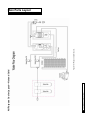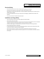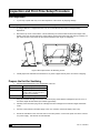
1
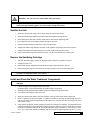
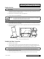
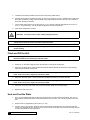
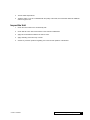
Cat. No. 01023621 Rev. A 06/01/10 DCO # 011759 Installation, Operation & Service Instructions with Parts List CULLIGAN® All Purpose Bottle-free Cooler Featuring: • Antimicrobial Protection Models: D1021870 ©2010 Culligan International Company Printed in USA Attention Culligan Customer: Your local independently operated Culligan dealer employs trained service and maintenance personnel who are experienced in the installation, function and repair of Culligan equipment. This publication is written specifically for these individuals and is intended for their use. We encourage Culligan users to learn about Culligan products, but we believe that product knowledge is best obtained by consulting with your Culligan dealer. Untrained individuals who use this manual assume the risk of any resulting property damage or personal injury. Culligan Coolers are combined with selected Culligan water treatment components to create a system specifically tailored to match the customer application. WARNING! Prior to servicing equipment, disconnect power supply to prevent electrical shock. NOTE This system is not intended for use where water is microbiologically unsafe or with water of unknown quality. WARNING! If incorrectly installed, operated or maintained, this product can cause severe injury. Those who install, operate, or maintain this product should be trained in its proper use, warned of its dangers, and should read the entire manual before attempting to install, operate, or maintain this product. Products manufactured and marketed by Culligan International Company (Culligan) and its affiliates are protected by patents issued or pending in the United States and other countries. Culligan reserves the right to change the specifications referred to in this literature at any time, without prior notice. Culligan, Aqua-Cleer, Culligan Man and www.culligan.com are trademarks of Culligan International Company or its affiliates. Culligan International Company 9399 West Higgins Road, Suite 1100 Rosemont, Illinois 60018 For Technical Service Help call: 1-800-723-3426 ext. 2 To Order Innowave Parts call: 1-800-723-3426 ext.1 To Order Culligan Parts call: 1-800-428-2828 www.culligan.com WARNING! This device complies with part 15 of the FCC rules subject to the two following conditions: 1) This device may not cause harmful interference, and 2) This device must accept all intereference received including interference that may cause undesired operation. This equipment complies with Part 15 of the FCC rules. Any changes or modifications not expressly approved by the manufacturer could void the user’s authority to operate the equipment. Changes or modifications not expressly approved by the party responsible for compliance could void the user’s authority to operate the equipment. Installation and Operation Instructions with Parts List Culligan® All Purpose Bottle-free Cooler Models from 2010 Contents Attention Culligan Customer:...............................................ii Electrical Wiring Diagram................................................. 24 Key Pre-Delivery Activities.................................................iv All Purpose Cooler Wetted Parts List............................... 25 Introduction......................................................................... 1 All Purpose Cooler Wetted Parts Illustration.................... 26 All Purpose Overview......................................................... 3 All Purpose Cooler Main Parts List................................... 27 Main Parts Layout.............................................................. 4 All Purpose Cooler Main Parts Illustration........................ 28 Safety Information.............................................................. 5 Single Head Manifold and Available Cartridges............... 29 Inspection and First-Time Setup Procedure....................... 6 Appendix Overview.......................................................... 30 Installing the All Purpose Cooler........................................ 9 Appendix A....................................................................... 31 Operating an All Purpose Cooler...................................... 12 Appendix B....................................................................... 32 Dispensing Hot and Cold Water....................................... 13 Appendix C....................................................................... 35 Maintenance and Service................................................. 14 Appendix D....................................................................... 39 Sanitizing the All Purpose Cooler..................................... 16 Descaling the All Purpose Cooler..................................... 18 Troubleshooting................................................................ 21 Technical Specifications................................................... 22 Warranty........................................................................... 23 Cat. No. 01023621 Contents iii Key Pre-Delivery Activities CAUTION! The cooler and the water treatment equipment must be properly prepared before the system is delivered to the customer. All Purpose Filter Systems All Purpose Aqua-Cleer Filter—see Appendix A, Figure 10, on page 36. • Uses: Two Carbon Block filters in two (2) E-Z Change heads. All Purpose Reverse Osmosis Systems All Purpose Aqua-Cleer RO—see Appendix B, Figure 13 on pages 37–39. • Uses: Carbon block and RO 30 cartridges in two (2) E-Z Change heads with storage tank and inline post carbon filler. • For detailed instructions about Aqua-Cleer components please refer to the complete Installation, Operation and Service Manual, Cat. No. 01020219. All Purpose LC-100 RO—see Appendix C, Figure 17 on pages 40. • Uses: Preferred Series 250 Filter and LC-100 RO with storage tank and inline post carbon filter. • For detailed instructions about Aqua-Cleer LC components please refer to the complete Installation, Operation and Service Manual, Cat. No. 01882074. All Purpose AC50 RO—see Appendix D, Figure 21 on page 44. • Uses: AC50 inline post carbon filter and storage tank. • For detailed instructions about AC 50 components please refer to the complete Installation, Operation and Service Manual, Cat. No. 01018587. iv Culligan® All Purpose Cooler iv Cat. No. 01023621 Pre-Delivery Activity: Prepare and Flush Water Treatment Components CAUTION! All RO Membranes will require a 24-hour flush to drain. All flushing of membranes and filters must be done with chlorine-free, filtered, softened water. Activity All Purpose Aqua-Cleer Filter All Purpose Aqua-Cleer RO All Purpose LC-100 RO All Purpose AC50 RO Flush the filters to drain for at least five (5) minutes with filtered soft water c Verify that system includes Automatic Shut-Off Valve (P1021587) c c c Verify that system includes Check Valve (P1021588) c c c Verify system includes Air Gap (44403001 or equivalent) for system drain c c c Flush the RO cartridge to a drain with filtered softened water for 24 hours prior to installation c c c Flush the carbon block filter to drain for at least five (5) minutes until there are no more carbon fines observed. c Activate the Preferred Series 250 cartridge and thoroughly flush per the detailed instructions c Flush the pre-carbon filter and sediment filters to drain c Flush the carbon post filter to drain c c c Sanitize and flush the storage tank c c c Pre-Delivery Activity: Prepare and Flush Cooler for Service Activity All Purpose Cooler Unpack the Cooler. c Inspect the Cooler for any shipping damage. c Flush and test the Cooler. c See the appendixes for details about these activities. Cat. No. 01023621 Key Pre-Delivery Activities v This page intentionally left blank. vi Culligan® All Purpose Cooler vi Cat. No. 01023621 Introduction Thank you for purchasing the Culligan All Purpose Cooler. The Culligan All Purpose Cooler brings a unique, fresh approach and a new look to point-of-use water treatment systems in the marketplace. The system’s contemporary color scheme complements every office environment. Unlike a bottled water cooler, incoming tap water is treated as it is needed, so the water is always fresh and great tasting. Best of all, there are no bottles to change and the supply is virtually unlimited. The Culligan All Purpose Cooler is enhanced with a unique anti-microbial agent, based on silver ion technology, that inhibits the growth of a broad range of micro-organisms. This Agent is incorporated into the plastic parts of the system at the time of manufacture, giving it built-in continuous anti-microbial protection against bacteria, mold and fungi, making it cleaner and safer. The Culligan All Purpose Cooler comes with two empty single heads installed inside that will enable you to configure it for the condition of the incoming water supply. You decide on the filtration needed and then simply twist the filters into the filter heads behind the lower front panel. Culligan All Purpose Cooler systems come with a 1 gallon (4 liters) cold tank. To create the most common two stage filtration system in the tower model, we recommend the following: • First: 5 micron Carbon Block (Culligan P1020266) to reduce chlorine. • Second: 5 micron Carbon Block (Culligan P1020266) to reduce chlorine. Of course, your local water conditions may require alternate selections for the wide range of Aqua-Cleer® cartridges offered by Culligan. In order for the water treatment system to continue to provide high quality water, a thorough understanding of the system and its operation is required. Review this manual before making any attempt to install, operate, or service the system. Installation or maintenance done on this system by an untrained service person can cause major damage to equipment or property damage. This publication is based on information available when approved for printing. Continuing design refinements could cause changes that may not be included in this publication. Safe Practices Throughout this manual there are paragraphs set off by special headings. Notice Notice is used to emphasize installation, operation or maintenance information which is important, but does not present any hazard. For example, NOTICE The nipple must extend no more than 1 inch above the cover plate. Caution Caution is used when failure to follow directions could result in damage to equipment or property. For example, CAUTION! Disassembly while under water pressure can result in flooding. Cat. No. 01023621 Introduction 1 Warning Warning is used to indicate a hazard which could cause injury or death if ignored. For example, WARNING! Electrical shock hazard! Unplug the unit before removing the timer mechanism or cover plates! The CAUTION and WARNING paragraphs are not meant to cover all possible conditions and situations that may occur. It must be understood that common sense, caution, and careful attention are conditions which cannot be built into the equipment. These MUST be supplied by the personnel installing, operating, or maintaining the system. Be sure to check and follow the applicable plumbing codes and ordinances when installing this equipment. Local codes may prohibit the discharge of acid or caustic solutions to drain. An extra solution tank should be used to neutralize the solution before discharging to drain. Use protective clothing and proper face or eye protection equipment when handling chemicals or power tools. NOTE The Culligan All Purpose Cooler is not intended for use with water that is microbiologically unsafe or of unknown quality without adequate disinfection either before or after the system. NOTE Check with your public works department for applicable local plumbing and sanitation codes. Follow local codes if they differ from the standards used in this manual. To ensure proper and efficient operation of the All Purpose Cooler to your full satisfaction, carefully follow the instructions in this manual. 2 Culligan® All Purpose Cooler 2 Cat. No. 01023621 All Purpose Overview All Purpose Overview Cold Tank The cold tank is manufactured from 304 Stainless Steel which is non-corrosive. The cold water temperature is preset at approximately 41°F (5°C) by the factory. The capacity of the cold tank is 1 gallon (4 liters). The cold tank temperature is controlled by a thermostat that is set at the factory. PCB The PCB (Printed Circuit Board) is the control unit for the All Purpose Cooler. It is responsible for the selection and dispensing of water. The PCB drives an LED which informs the user of the status of the unit. The PCB has a power on indicator and also indicates to the user what option of water is currently selected by changing color. Compressor The compressor uses R134a non-ozone depleting refrigerant gas. The compressor is controlled by an electromechanical thermostat, which controls the temperature of the water in the cold tank unit. Water Pipe and Fittings All water connection fittings are approved to NSF standard 61. The machine is connected to the water supply by a 1/4” female bulkhead fitting. The entire internal water circuit and all components which come in contact with water are food grade NSF / WRAS approved. Water Valves Water dispensing to the customer is achieved by means of a 24V DC electrical solenoid valve. The valves are energized each time the customer pushes the dispense button for a drink. DC voltage is used for safety. Plastic Panels The molded panels are made from recyclable ABS plastic. All the ABS plastic panels are UV resistant and meet the standards of CE and UL. Cat. No. 01023621 All Purpose Cooler Overview 3 4 Culligan® All Purpose Cooler Figure 1.All Purpose Cooler layout. All Purpose Cooler Layout—Hot and Cold Main Parts Layout Safety Information Electrical Safety • Only connect the power cord to a 120V, 15A (GFI preferred) properly grounded outlet. • Never pull the power plug from the outlet with a wet hand or allow the plug to get wet. • K eep the power cord out of heavy traffic areas. To avoid a fire hazard, never put the power cord under rugs, near radiators, stoves or heaters. • Do not use a damaged power cord or plug. If the power cord is damaged, a qualified service technician must replace it. • Do not use an extension cord with the All Purpose Cooler. Installation and Usage Safety • Keep the All Purpose Cooler away from direct sunlight and excessive humidity. • Keep at least 3 inches from the wall. • D o not lay the All Purpose Cooler down on its side. If for some reason the unit was placed on its side, it must stand upright for a minimum of 2 hours before operation to allow the compressor to stabilize. • Connect the water supply to a cold water line only. Feed water over 105°F (41°C) can damage the filters. • Never install the system where it could freeze. • If the feed water pressure is over the recommended operating pressure of 60 psi (4 bar), install a pressure-reducing valve in the water line. Be aware of pressure transients. • Filters should be replaced on schedule. Overused filters will deteriorate the performance of the system. • Drain the water out of the All Purpose Cooler after long periods of non-use; this will allow a fresh batch of water to fill the system. Cat. No. 01023621 Safety Information 5 Inspection and First-Time Setup Procedure Unit Inspection 1. In your shop, unpack and carry out a visual inspection of the unit for any shipping damage. NOTE All preparation work should be done in a clean area. A separate room is recommended. 2. A Culligan IQR form is shipped with each unit. Fill out the IQR form and return to Culligan Quality Department. 3.Remove the top cover of the machine. This is retained by two screws located under the front edge at the bottom of the cover and two clips in the same location. Remove the screws and push clips up to release. To gain easier access to the screws, tilt the machine backward at an angle of 10 degrees. 10° Figure 2.All Purpose Cooler unit balancing screws. 4. Visually inspect the internals of the machine for any wires or pipes that may have come loose in shipping. Prepare the Unit for Sanitizing 1. Plug the filter heads based on the configuration of the unit. Aqua-Cleer® Filter Use bypass plugs (P1020279). Aqua-Cleer® RO Use bypass plugs (P1020279). LC 100 RO Use bypass plugs (01010098). Plug the restrictor outlet in the RO head with a 3/8" stem plug (01005650). AC 50 RO Attach empty housings to manifold. 2. Using the sanitizer cartridge, remove the bottom screw plug of the sanitizer cartridge and pour in 15 mL of unscented, liquid chlorine bleach (6% Sodium Hypochlorite) 3. Carefully screw the bottom plug into the cartridge and insert cartridge into the left hand single head inside cooler 4. Connect a clean, filtered, soft water supply to the unit. Pressure must be 40–60psi (2.8–4.1 bar). 5. Ensure the red switch on the rear of the unit is in the OFF position. Connect the power cord to the unit and to a power supply. 15A with GFI is recommended. 6 Culligan® All Purpose Cooler 6 Cat. No. 01023621 CAUTION! The unit is now live. Take suitable safety precautions. NOTE It may take several minutes before the hot tank is full and water begins to flow from the dispensing head. Flush approximately 3 gallons (11 liters) of water through the hot tank. Sanitize the Unit 1. Slowly turn ON the water supply. The incoming water will mix with the chlorine. 2. Press and hold the large dispense (A) button to start flushing water through the unit. 3. Stop flushing when water with a chlorine smell starts to flow from the dispensing head. 4. Do not dispense any of the sanitizing solution through the hot tank. 5. Allow the sanitizer solution to stand in the unit for 20–30 minutes. 6. Activate and hold the large dispense (A) button. Flush 3 gallons through the unit and the cold tank. 7. Activate and hold the Hot buttons (both B and C). Flush 3 gallons through the hot tank. 8. Verify that all chlorine has been rinsed from the hot, cold, and room faucets with a chlorine test. Remove the Sanitizing Cartridge 1. Turn OFF the water supply. Activate the dispense button to relieve any pressure in the unit. 2. Unplug the power cord. 3. Remove the sanitizer cartridge and EZ head. Reconnect the inlet feed tubing to the unit. 4. Remove all bypass plugs from the heads or the empty housings on an AC 50 RO configuration. NOTE Prepare all filters, RO cartridges, and the RO storage tank strictly in accordance with the instructions included in the Appendix section of this manual. Install and Flush the Water Treatment Components NOTE If prep station has a plumbed in RO, then use the RO water for final rinse, bypassing the installed cartridges. 1. If the unit is going to be configured with an LC-100 or AC 50 RO system, remove the EZ heads and install the other components. 2. Install the properly prepared water treatment equipment inside the All Purpose Cooler. 3. Turn ON the water supply and plug in the unit. 4. Slowly turn ON the water supply. Open the ball valve on the top of the full RO water storage tank. 5. Flush 1–2 gallons (4–8 liters) of hot water, 1–2 gallons (4–8 liters) of cold water of water through the unit to flush the new water treatment components and the water in the unit. Verify the water is running clear of any carbon fines or color. 6. Verify that the compressor starts by feeling the head of the compressor for vibration. The temperature in the cold tank should reach its target temperature within 45 minutes. When the unit has reached target cold temperature, the compressor will cycle off. The target temperature range is between 41° F and 46° F (5° and 8° C) (+/- 5%). The hot tank will take considerably less time to reach its target temperature of 185° F (+/- 5%). Cat. No. 01023621 Inspection and First-Time Setup Procedure 7 7. Adjust the cold water temperature by regulating the thermostat situated at the back of the unit. This thermostat is set at a specific point at the factory. This point is marked out by a small dot situated on the outside of the thermostat. 8. After 45 minutes, verify proper heating and chilling. 9. Turn the Red Power Switch OFF. 10. Hold a pitcher under the Hot dispensing faucet. Depress the Hot unlock button, followed by the Hot dispense button, and allow water to continuously run through the hot tank until the water runs cool from the faucet. This is done to avoid scalding during draining. 11. Disconnect the power cord from the 120 Volt electrical outlet. 12. Turn off the water supply to the unit. 13. Disconnect the water supply from the unit. 14. Remove filters to allow room to drain hot and cold tanks. 15. Make sure you have a suitable container in order to drain the All Purpose Cooler. Disconnect the 90° elbow after the solenoid. Lower tubing to drain hot tank. Reconnect 90° elbow. Repeat step to drain cold tank. Wipe down any excess water inside and around the unit. 16. Re-install filter cartridges. 17. Return cooler to the original box. 18. The All Purpose Cooler should be installed within 24 hours. NOTE Prepare all filters, RO cartridges, and the RO storage tank strictly in accordance with the instructions included in the Appendix section of the manual 8 Culligan® All Purpose Cooler 8 Cat. No. 01023621 Installing the All Purpose Cooler Position the Unit NOTE Per Culligan Corporate policy, you must install an external leak controller during install of the All Purpose Cooler (Part # D1018733) 1. Locate the unit as close to an electrical connection and feedwater water supply as possible with a 3 inch (8 cm) clearance at both sides and back of the unit. 2. Mount the unit on a firm flat surface so that it cannot topple over. 3. Level the machine using the adjustable feet. CAUTION! The machine should not be exposed to direct sunlight, heat sources, or an ambient air temperature above 90°F (32°C) or below 37°F (3°C). NOTE The water supply and electrical supply should be within 6 ft (1.8 m) of the unit for ease of installation. 4.Remove the lower front cover. This is retained by two screws located under the front edge at the bottom of the cover and two clips in the same location. 5. Remove the screws and push clips up to release. To gain easier access to the screws, tilt the unit backward at an angle of 10 degrees. 10° Figure 3. All Purpose unit balancing screws. Establish the Water Connection 1. Establish the water connection. 2. The use of a pressure regulator is recommended for water supplies that have pressure fluctuations. This should be installed on the water supply before the inlet connection to the unit. Minimum operating pressure for the unit to work suitably is 40 psi (2.8 bar). The ideal operating pressure is of 60 psi (4.1 bar). NOTE At pressures higher than 80 psi (5.5 bar), the unit will not function correctly and can lead to leaks. Pressure below 40 psi (2.8 bar) will require the use of a booster pump for proper RO performance. 3. Set pressure regulators at 60 psi (4.1 bar). 4.Flush the water supply pipe until it runs clear before making the water connection to rear of the unit. Cat. No. 01023621 Installing the All Purpose Cooler 9 5.The filters were already installed in the unit at the shop during initial start up. 6. Plug the power lead into the back of the unit. As soon as you plug the unit into a suitable power supply (15A GFI outlet is preferred), voltage will be available to the PCB and solenoid valves, and you can now start to flush water through the machine. 7. The hot water temperature is set at 185°F (85°C) (+/- 5%) and the cold water temperatures is set at 41°F (5°C) (+/- 5%)at the factory. It is not possible to adjust the hot water temperature. 8. Verify proper temperature at install. CAUTION! The unit is now live. Take suitable safety precautions. NOTE Do not turn on the red switch (heater and compressor switch) at the rear of the machine. This switch should only be turned on once the hot tank is filled with water. NOTE Do not adjust the cold thermostat past the factory set point of 41°F (5°C), as this may result in the system freezing. Flush and Fill the Unit NOTE For units using RO treatment: Because the RO make-up rate is so slow, use a full storage tank (with RO treated water) for the following fill and flush steps. 1. Connect the full storage tank of RO water to a tee installed ahead of the unit solenoids. 2. Slowly turn on the water supply and open the ball valve on the full RO storage tank. 3.Select the hot water option. Press and hold the dispense buttons (both B and C buttons) to start flushing water through the filters and hot tank. NOTE It may take several minutes before the hot tank is full and water begins to flow from the dispensing head. Flush one to two (1–2) gallons (4–8 liters) of water. 4. Select the cold water option. Press and hold the cold dispense button (A) to fill the cold tank. NOTE It may take several minutes before the cold tank is full and water begins to flow from the dispensing head. Flush one to two (1–2) gallons (4–8 liters) of water. 5. Check the unit for any water leaks and ensure that all water fittings are secured properly. 6. Replace the lower front cover. Heat and Cool the Water 1. O nce you are satisfied that water is passing through both the hot and cold tank successfully, then turn on the red switch (heater/compressor switch) located at the rear of the unit. The unit will now start to heat and chill. 2. Heat the water to approximately 185°F (85°C) (+/- 5%). 3. Cool the water in the cold tank. When the unit has reached the set temperature, the compressor will stop running. The temperature may continue to drop as any ice that has formed on the sides of the tanks will start to melt and equalize the tank temperature. 10 Culligan® All Purpose Cooler 10 Cat. No. 01023621 4. Test the water temperatures. 5.Taste the water. If you are not satisfied with the quality of the water, check the filters and flush additional water through the unit. Inspect the Unit 1. Check the unit to make sure it is electrically safe. 2. Check that the unit is clean and functions to the customer’s satisfaction. 3. Apply service maintenance label to the side of cooler. 4. Apply marketing cross-sell to top of cooler. 5. Answer any customer questions regarding use of the unit and operation of the buttons. Cat. No. 01023621 Installing the All Purpose Cooler 11 Operating the All Purpose Cooler Your All Purpose Cooler is ready for use when the three (3) colored LEDs on the front panel are all illuminated. Operating the machine is very simple. 1. First, place a cup in the dispense area. 2. Select the water temperature of your choice. 3. Press the dispense button until your cup is filled to the required level. CAUTION! HOT WATER c Always place cup / mug in the center of the bulls eye marking on the drip tray. c Always use a ceramic cup or a cup suitable for use with hot water. c Do not hold cup or place hands in dispensing area while dispensing water. c Do not dispense water in a stop-start style of vending. Hold button continuously until cup is full). c Never try to fill more than one vessel at a time. 12 Culligan® All Purpose Cooler 12 Cat. No. 01023621 Dispensing Hot and Cold Water Dispensing Cold Water 1. For Cold Water, press A button. The button backlight will light blue and the LED will blink. The machine will dispense cold water. Dispensing Hot Water 1. For Hot Water, press both the B and C buttons. The button backlight will light red and the red LED will blink. The machine will dispense hot water. Cat. No. 01023621 Dispensing Hot and Cold Water 13 Maintenance and Service NOTE All personnel should be aware of company requirements for their own cleanliness and hygiene when servicing and sanitizing a unit. All Purpose Cooler Maintenance/12-Month Service Interval Every twelve (12) months, the filters should be changed. Units in dusty or high use locations may need more frequent servicing. A machine with the hot water option may require removing any Calcium build-up inside the hot tank, depending on local water conditions and the type of water treatment. NOTE A full RO storage tank must be available for flushing steps. CAUTION! The machine should not be exposed to direct sunlight, heat sources, or an ambient air temperature above 90°F (32°C) or below 37°F (3°C). Do not clean this appliance with a water jet. NOTE You must use latex gloves when handling the filters or any components that have contact with the drinking water. Prepare the Unit for Sanitizing 1. Turn OFF the water supply. Activate the dispense button to relieve any pressure in the unit. 2. Turn OFF the red switch at the rear of the unit and unplug the power cord. 3. On RO systems, close the ball valve on the top of the RO storage tank. 4. Remove and dispose of all old filters from the unit. 5. On units using RO, disconnect the storage tank from the product line tee and plug the tubing tee with a ¼” stem plug (01001142). Sanitize the storage tank separately. 6. Plug the filter heads based on the configuration of the unit. Aqua-Cleer® Filter Use bypass plugs (P1020279). Aqua-Cleer RO Use bypass plugs (P1020279). LC 100 RO Use bypass plugs (01010098). Plug the restrictor outlet in the RO head with a 3/8" stem plug (01005650). AC 50 RO Attach empty housings to manifold. ® 7. On units using RO, remove the carbon post filter. Use a ¼” tube x ¼” tube connector (00403729) to join the product tubing where the filter was located. 8. Using the sanitizer cartridge, remove the bottom screw plug of the sanitizer cartridge and pour in 15 mL of unscented, liquid chlorine bleach (6% Sodium Hypochlorite) 9. Carefully screw the bottom plug into the cartridge and insert cartridge into the left hand single head inside cooler 10. Plug in the power cord. 14 Culligan® All Purpose Cooler 14 Cat. No. 01023621 CAUTION! The unit is now live. Take suitable safety precautions. Cat. No. 01023621 Maintenance and Service 15 Sanitizing the All Purpose Cooler Sanitize the Unit 1. Slowly turn ON the water supply. The incoming water will mix with the chlorine. 2. Press and hold the large dispense (A) button to start flushing water through the unit. (See page 12 for details on the operation of the control buttons). NOTE It may take several minutes before the cold tank is full and water flows from the dispensing head. 3. Stop when water with a chlorine smell starts to flow from the dispensing head. 4. Do not dispense any of the sanitizing solution through the hot tank. 5. Allow the sanitizer solution to stand in the unit for 20-30 minutes. 6. Activate and hold the large dispense (A) button. Flush 3 gallons through the unit and the cold tank. 7. Activate and hold the hot (both B and C) buttons. Flush 3 gallons through the hot tank. Remove the Sanitizing Cartridge 1. Turn OFF the water supply. Activate the dispense button to relieve any pressure in the unit. 2. Unplug the power cord. 3. Remove the sanitizer cartridge and EZ head. Reconnect the inlet feed tubing to the unit. 4. Remove all bypass plugs from the heads or the empty housings on an AC 50 RO configuration. Replace the Filter NOTE Prepare all filters, RO cartridges, and the RO storage tank strictly in accordance with the instructions included in the Appendix section of this manual. 1. On units using RO, reconnect a full RO storage tank that has been sanitized separately per the instructions in the Appendixes. 2. Install new filters. 3. On units using RO, reconnect the carbon post filter. 4. Plug in the power cord. CAUTION! The unit is now live. Take suitable safety precautions. 5. Replace batteries on external leak controller. 16 Culligan® All Purpose Cooler 16 Cat. No. 01023621 Flush and Return to Service 1. Slowly turn ON the water supply. Open the ball valve on the top of the full RO water storage tank. 2. Flush 1–2 gallons (4–8 liters) of hot water, 1–2 gallons (4–8 liters) of cold water through the unit to flush the new water treatment components and the water in the unit. (See page 13 for details on the operation of the control buttons). Verify the water is running clear of any carbon fines or color. 3. Turn ON the Red Power Switch to start the chilling and heating processes. 4. Verify that the compressor and heater are both working: place a hand on top of the compressor to feel for vibration, then dispense water from the hot tank (after five minutes), noting a temperature increase in the water. 5. Visually inspect water connections for any leaks. 6. Remove the faucet nipple and inspect to see if there are any cracks or scratches or lime-scale build up on the nipple, if so then replace it. If the faucet nipple is OK, sanitize it with a bacterial wipe or spray and put back using clean latex gloves. 7. Remove and clean the drip tray and grill. If the grill is damaged or heavily stained it should be replaced. 8. Wipe all surfaces around the drip tray and faucet nipple area with a bacterial cleaning wipe or spray. 9. Return the drip tray to the unit. 10. Close the top cover and front cover of the unit. 11. Taste the water. Check the unit is clean and functions to the customer’s satisfaction. If you are not satisfied with the quality of the water, check the filters and flush additional water through the unit. Answer any customer questions regarding use of the unit. 12. Update service maintenance label. Cat. No. 01023621 Sanitizing the All Purpose Cooler 17 Descaling the All Purpose Cooler Maintenance and Service Interval All Purpose units using an RO configuration should rarely need to be descaled. NOTE A full RO storage tank must be available for flushing steps. NOTE All personnel should be aware of company requirements for their own cleanliness and hygiene when servicing and sanitizing a unit. NOTICE You must use latex gloves when handling the filters or any components that have contact with the drinking water. NOTE Use the Culligan Aqua-Cleer® sanitizing cartridge (P1020277) when descaling the All Purpose Cooler. The All Purpose Cooler units using a filter configuration should be de-scaled at least once every twelve (12) months if installed on a hard water supply or sooner if symptoms of hot tank fouling occur. Common Signs of Hot Tank Scaling Requiring Descaling • The hot tank sounds like it is boiling inside. • Steam is escaping from the dispensing nozzle. • A double stream of water flows from the faucet and the vent behind the faucet. • The hot water dispenses abnormally from the unit. NOTE Certain symptoms may signify the need to descale the cold tank, though these cases are very rare. If the cold water dispenses a double stream, or if cold water drizzles from the faucet for an extended time (longer than 15 seconds) after the dispensing button has been released, then you may need to descale the cold tank. Prepare the Unit for Descaling 1. Turn OFF the water supply. Activate the dispense button to relieve any pressure in the unit. Figure 4. 2. Turn OFF the red switch at the rear of the unit and unplug the power cord. 3. Remove all the filters from the unit and set them aside in a clean place. 4. Place the Culligan Aqua-Cleer® sanitizing cartridge (P1020277) in the left-hand single head 5. On units using RO, Turn off the tank ball valve, disconnect the storage tank from the product line tee and plug the tubing tee with a ¼” stem plug (01001142). 6. Plug the filter heads based on the configuration of the unit. Aqua-Cleer® Filter Use bypass plugs (P1020279). Aqua-Cleer® RO Use bypass plugs (P1020279). LC 100 RO Use bypass plugs (01010098). Plug the restrictor outlet in the RO head with a 3/8" stem plug (01005650). AC 50 RO Attach empty housings to manifold. 8. On units using RO, remove the carbon post filter. Use a ¼” tube x ¼” tube connector (00403729) to join the product tubing where the filter was located. 18 Culligan® All Purpose Cooler 18 Cat. No. 01023621 NOTE When mixing the descaling solution in the empty sanitizing cartridge, try adding a little red or green food coloring to the mixture. adding food coloring will make it easier when flushing the unit later when you need to verify all descaler solution has been flushed from the unit. 9. Remove the bottom screw plug of the sanitizer cartridge and pour 1 bag of ScaleKleen (7 oz. bag of nontoxic citric acid-based descaler, Innowave part # 01-2076) into the sanitizer cartridge. Add red or green food coloring to the solution in order to make it easier to tell when the solution is completely flushed. In lieu of food coloring, a pH test kit can be used. 10. Carefully screw the bottom plug into the cartridge and insert cartridge into the left-hand EZ head. 11. Plug in the power cord. CAUTION! The unit is now live. Take suitable safety precautions. CAUTION! DO NOT turn on the red switch at the rear of the unit. Descale the Unit 1. Slowly turn ON the water to mix and deliver the descaling solution to the unit. 2. Select the hot water option. Press and hold both the B and C buttons to flush 2-3 cups from the dispenser nozzle which will fill the hot tank with the descaling chemical. 3. Turn ON the red switch at the rear of the unit. 4. Allow the hot tank to heat and descale for at 10-20 minutes. 5. If the cold tank requires descaling, dispense 2-3 cups from the cold side and allow a 10-20 minute wait. 6. After the wait period, but prior to removing the sanitizer cartridge, try dispensing water from the hot side (and/or cold side if it needed descaling) and verify proper operation. A smooth stream should come out of the dispensing nozzle. In some extreme circumstances, additional treatments and soak time will be required for the descaler to effectively work. 7. Flush 3 gallons (11 liters) of hot water, 3 gallons (11 liters) of cold water through the unit to flush the descaling chemicals from the unit. Verify the water is running clear of any color. Make sure all descaler has been adequately flushed from the system. 8. Turn OFF the water supply. Activate the dispense button to relieve any pressure in the unit. Remove the sanitizer cartridge from EZ head. 9. Remove the faucet nipple and inspect to see if there are any cracks or scratches or lime-scale build up on the nipple, replace it. If the faucet nipple is okay, sanitize it with a bacterial wipe or spray and put back using clean latex gloves. 10. Re-Install the filters. 11. On units using RO, reconnect the RO water storage tank. Cat. No. 01023621 Descaling the All Purpose Cooler 19 NOTE If the filters are new, the preparation of all filters, RO cartridges and the RO storage tank must be done strictly in accordance with the instructions included in the Appendix section of this manual. 12. On units using RO, reconnect the carbon post filter. Flush and Return Unit to Service 1. Turn on the water supply. Open the ball valve on the top of the full RO water storage tank. 2. With the filters reinstalled, flush 1–2 gallons (4–8 liters) of hot water, 1–2 gallons (4–8 liters) of cold water through the unit to flush the new water treatment components and the water in the unit. Verify the water is running clear of any carbon fines or color. 3. Visually inspect water connections for any leaks. 4. Remove and clean the drip tray and grill. If the grill is damaged or heavily stained it should be replaced. 5. Wipe all surfaces around the drip tray and faucet nipple area with a bacterial cleaning wipe or spray. 6. Return the drip tray to the unit. 7. Close and screw down top and front cover of the unit. 8. Taste the water. Check the unit is clean and functions to the customer’s satisfaction. If you are not satisfied with the quality of the water, check the filters and flush additional water through the unit. Answer any customer questions regarding use of the unit. 20 Culligan® All Purpose Cooler 20 Cat. No. 01023621 Troubleshooting The following is a list of different problems that may be found while installing and operating the All Purpose Cooler. NOTE Fault finding must only be carried out by trained personnel. Symptom Possible Cause NO FLOW OF WATER THERE IS FLOW FOR THE HOT WATER, BUT NO FLOW FOR THE COLD WATER Solution In this case, make sure that there is a water supply to the unit and that it is turned on. If an anti-flood or leak detection device is installed, please check and reset if necessary. For units with EZ heads, ensure that the filter is twisted all the way into the head; otherwise the valve inside the filter head will not be opened. Check to see that the filter is not blocked with sediment This may be a result of the water inside the cold tank mechanism being frozen. Verify that the thermostat is set at the factory setting. Disconnect the power mains from the back of the machine and allow the ice inside the cold tank to melt. WATER DISPENSED BY THE UNIT IS NEITHER HOT NOR COLD Make sure that the red heater/compressor switch at the back of the unit is turned on. THE POWER INDICATOR IS NOT ON Make sure that the unit is plugged in correctly and that the red switch is on. If the unit is properly set up, then remove the top cover of the machine and check the fuse on the back of the unit. BAD TASTE Flush the unit for a period of 15 minutes. If the bad taste persists taste the water coming directly from the filter, if still bad change the filter, or contact your authorized service provider. LOW FLOW OF COLD WATER If this happens in the cold water circuit, there may be a problem with freezing. Please refer to “There is flow for the hot water, but no flow for the cold water”. LOW FLOW OF WATER FOR ALL CIRCUITS OF THE UNIT The filter may require changing, or there is low water supply pressure. Ensure that the filter is not blocked. LOW FLOW OF HOT WATER Indicates that the hot tank needs to be de-scaled. HOT WATER IS COLD If all the electrical connections are fitted properly, there is a chance that the overload mechanism has been triggered. COLD WATER IS WARM Cat. No. 01023621 In this case, unplug the unit, remove the upper and lower front panels to gain access to the hot water tank. On the side of the hot tank there is a manual reset button for the overload mechanism. Press the button and reassemble all the panels. Plug in the unit and make sure it continues to heat up the water as normal. Make sure that you are not testing the ambient option. Check the thermostat is at the set point. Make sure the unit is not in direct sunlight or a room with a high ambient temperature (32ºC +). Ensure the heater/compressor switch is on. If none of the prior are the source of the issue, then assume standard refrigeration fault finding procedures. Troubleshooting 21 Technical Specifications Item Width / Depth / Height All Purpose Cooler 15.5” x 14.5” x 40.5” 343mm x 368mm x 1029mm Water Connection 1/4” Tubing Cold Water Temp 41 - 44°F (5 - 7°C) Cold Tank Size 1 Gallon (4 Liters) Hot Water Temp 185°F (85°C) Hot Tank Size Min/Max Water Pressure Recommended Water Pressure 0.4 Gallon (1.5 Liters) 40 - 80 psi (2.8 - 5.5 bar) 60 psi (4.1 bar) Weight (Dry) 64lbs (29kg) Electrical Supply 120V / 60Hz Heater 500W Refrigeration Gas R134a 2.3 Oz (65 grams) Environmental Information NOTE This information is provided as guidance only. Energy consumption will be affected by incoming water temperature, room temperature and usage patterns. PRODUCT/MODEL DESCRIPTION All Purpose Cooler ENERGY COMSUMPTION IN NORMAL OPERATION MAXIMUM NOISE LEVEL Kilowatt/Hours (KwH) Decibels 2.51 0.2 Hot and Cold End of Life At the end of this product’s life, please ensure that it is disposed of in an environmentally friendly manner which is fully compliant with your Country requirements/guidelines. 22 Culligan® All Purpose Cooler 22 Cat. No. 01023621 Warranty Limited Warranty for the CULLIGAN® All Purpose Water Treatment System This water treatment system is guaranteed to the original user only to be free of defects in materials and workmanship for a period of one (1) year from the date of purchase, or initial lease, but in no event longer than twenty-four (24) months from the date of manufacture. innowave will not be liable for any cost of removal, installation, transportation, or any other charges which may arise in connection with a warranty claim. innowave will not be liable for damage or wear to products caused by abnormal operating conditions, accident, abuse, misuse, unauthorized alteration or repair, or if the products were not installed in accordance with innowave’s printed installation and operating instructions, or for any damage caused by hot water, freezing, flood, fire, or acts of God. In the event of a claim for warranty, the defective part must be returned to innowave, together with proof of purchase, installation date, failure date and supporting installation data. Any defective part returned to innowave incorporated must be sent freight prepaid. Documentation to support the warranty claim and/or a Return Authorization form must be included, if so instructed. Innowave, at its sole discretion, will determine whether to correct the defect or replace the unit, or will request that the unit be returned to innowave. Provided a claim is based on a defect in materials or workmanship; and provided the claim is made within the warranty period; and provided the user has used and maintained the equipment in accordance with the manufacturer’s instructions, innowave will replace the parts free of charge. If the unit is returned to innowave for repairs, the end user will pay the cost of freight in both directions. This warranty does not apply to damage caused by, or resulting from, shipping, accident, alteration, misuse or abuse, unauthorized or improper installation, or to units used outside the country where the unit was rented or purchased. The effects from chlorine corrosion, scaling and normal wear are specifically excluded from this warranty. Innowave hereby disclaims any and all implied warranties including, but not limited to, the implied warranties of merchantability and fitness for a particular purpose. The manufacturer or its agents shall not be liable for consequential damages, whether economic or otherwise, resulting from breach of this limited warranty. Failure to follow all instructions for operation and maintenance provided with this unit voids the warranty. This warranty gives you specific legal rights and you may also have other rights which may vary from country to country. Innowave USA LLC 11710 Stonegate Circle Omaha NE 68164 Toll-Free 1-800-288-1891 Cat. No. 01023621 Warranty 23 Electrical Wiring Diagram Hot and Cold Mark Description Mark Description 0V Thermostat for overheat SOL 1 1V Thermostat for overheat SOL 2 Hot solenoid valve H Hot water heater SOL 3 Ambient solenoid valve Cold solenoid valve LED1 Ambient water display SW1 Ambient mode switch LED2 Hot water display SW2 Hot mode switch LED3 Cold water display SW3 Water out switch MC Motor for compressor PF Power fuse TH1 Cold thermostat Heater/Compressor switch HR Hot thermostat PS1 T Transformer SW4 24 Culligan® All Purpose Cooler Filter timer reset switch 24 Cat. No. 01023621 All Purpose Wetted Parts List Hot and Cold Item Innowave Part Number Description 1 N/A BulkHead Fitting 1/4” x 1/4” 2 N/A O.D. 1/4” Blue Tube 3 N/A 1/4” Stem Elbow Connector 4 N/A Culligan Filter Head 5 N/A Culligan Filter 1 6 N/A O.D. 1/4” Blue Tube 7 N/A Culligan Filter Head 8 N/A Culligan Filter 2 9 N/A 1/4” Stem Elbow Connector 10 N/A O.D. 1/4” Blue Tube 11 N/A 1/4” Equal Tee Connector 12 12-5665 Solenoid Valve 24DC (Single) 13 12-5690 1/4” Non-Return Valve (Check-Valve for Solenoid) 14 N/A O.D. 1/4” Blue Tube 15 N/A 5/16” x 1/4” Reducing Elbow Connector 16 10-3062 Tube - Blue 8mm 17 N/A 2 Liter Cold Tank w/out UV Holder 18 10-3062 Tube - Blue 8mm 19 10-2700 Faucet 10-3048 Faucet Nipple Blue N/A Stainless Steel Gauze for Faucet 10-2701 Stainless Steel Insert for Faucet 10-2600 Natural Faucet O-Ring (Silicon White) 10-7040 Silicon Tube 5/16” for Hot Water 20 21 N/A O.D. 1/4” Blue Tube 22 N/A 1/4” Equal Tee Connector 23 10-7040 Silicon Tube 5/16” for Hot Water 24 12-5665 Solenoid Valve 24DC (Single 25 12-5690 1/4” Non-Return Valve (Check-Valve for Solenoid) 26 N/A O.D. 1/4” Blue Tube 27 N/A 5/16” x 1/4” Reducing Elbow Connector 28 10-3062 Tube - Blue 8mm 29 12-5615 Hot Tank 30 10-7040 Silicon Tube 5/16” for Hot Water 31 10-7040 Silicon Tube 5/16” for Hot Water NOTE N/A = Customer Specific / Not Stocked for Resale. Cat. No. 01023621 All Purpose Wetted Parts List 25 All Purpose Wetted Parts Illustration Hot and Cold Figure 5. Wetted parts diagram 26 Culligan® All Purpose Cooler 26 Cat. No. 01023621 All Purpose Main Parts List Item Innowave Part Number Description Item 1 2 3 Innowave Part Number Description 12-5640 Top Cover, Gray 27 N/A Culligan Filter 2 19-1069 Thermostat for Cold Tank 28 N/A Stem Elbow Connector NA Back Panel, Gray 29 12-5620 Front Down Insert Panel, Gray 30 12-5635 Front Down Panel, Gray 31 12-5670 Plastic Handle, Silver 4 12-5600 Power Switch (Red) 5 10-3014 Fuse Holder & Fuse 6 19-1090 Socket for Plug Connection 7 19-1015 Gasket for Power Socket 32 12-5275 8 12-5670 Side Panel, Gray (Left & Right Universal) Side Panel, Gray (Left & Right Universal) 33 10-2700 Faucet Faucet 9 12-8058 Plastic Handle, Silver 10-3048 Nipple Blue 10 N/A BulkHead Fitting 1/4” x 1/4” NA Stainless Steel Gauze for Faucet 11 NA Plastic Cap for 1/4” Bulkhead Fitting 10-2701 Stainless Steel Insert for Faucet 12 10-2200 Down Base 10-2600 Natural Faucet O-Ring (Silicon White) 34 12-5650 Drip Tray Insert Panel, Gray 35 12-5285 PCB Cover 36 12-5610 PCB 37 12-5660 Silicon Button Key Mat 38 12-5645 Upper Front Hatch/Insert Panel, Gray 39 12-5680 Culligan Logo/Label (Upper Display) 40 12-5625 Drip Tray Grill, Gray 41 12-5630 Drip Tray Body, Gray 42 12-3245 Power Transformer 43 N/A Upper Shelf 13 N/A Relay PCB 14 N/A Bolt M6*30 15 10-3083 Unit Control Rubber Feet 16 N/A Cushion for Solenoid Valve 17 12-5690 1/4” Non-Return Valve (Check-Valve for Solenoid) 18 12-5665 Solenoid Valve 24DC (Single) 19 N/A 1/4” Equal Tee Connector 20 12-5665 Solenoid Valve 24DC (Single) 21 12-5690 1/4” Non-Return Valve (Check-Valve for Solenoid) 22 N/A Filter Fixing Bracket 44 12-5285 Hot Tank N/A 1/4” Stem Elbow Connector 45 N/A 2 Liter Cold Tank w/out UV Holder 46 12-8102 Wire Condenser 23 24 N/A Culligan Filter Head 25 N/A Culligan Filter 1 26 N/A Culligan Filter Head NOTE N/A = Customer Specific / Not Stocked for Resale. Cat. No. 01023621 All Purpose Main Parts List 27 All Purpose Main Parts Illustration Figure 6.All Purpose model. 28 Culligan® All Purpose Cooler 28 Cat. No. 01023621 Single Head Manifold and Available Cartridges Part Number Description Case quantity P1020392 Single Head for Cartridges 6 Sediment Filter - 5 micron 12 SEDIMENT FILTERS P1020258 P1020260 Sediment Filter - 10 micron 12 P1020262 Sediment Filter - 25 micron 12 P1020266 Carbon Block Filter - 5 micron 12 P1020274 Large Carbon Block - 10 micron 12 P1020264 GAC Filter 12 P1020268 RO Membrane - 36 GPD 12 P1020270 RO Membrane - 50 GPD 12 P1020271 Nano Membrane 12 CARBON FILTERS RO and NANO MEMBRANES CARBON POST FILTERS (used after RO storage tanks) 01000124 GAC Carbon Post Filter, 1/4” Tube 10 00402807 GAC Carbon Post Filter, 1/4” Tube 50 SPECIALITY CARTRIDGES (used after RO membrane) P1020272 Arsenic Cartridge 6 P1020273 Perchlorate Cartridge 6 P1020274 Total Defense (same as Large Carbon Block) 12 P1020277 Sanitization Cartridge 6 P1020279 By Pass Plug 12 PLUG and SANITIZATION PARTS Other Part Numbers Referenced in this Manual 01010248 Adapter, 3/8” Stem x ¼” Tube 01010332 Restrictor Assembly, LC 100 RO Head P1021587 ASO (Automatic Shut Off Valve for RO Configurations) P1021588 Check Valve, ¼” Tube 01010098 Bypass Plug, Everpure Heads (For PS-250 and LC-100 Heads) 01021338 Plug, 3/8” Stem 01001142 Plug, ¼” Stem 00403729 Connector, ¼” Tube x ¼” Tube Cat. No. 01023621 Single Head Manifold and Available Cartridges 29