1
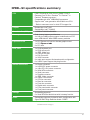
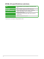
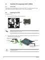
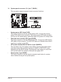
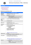
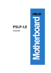
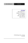
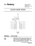
Motherboard
IPIBL-SI
E3513
First Edition
November 2007
Contents
IPIBL-SI specifications summary............................................................... iii
1.
2.
3.
Motherboard layout.......................................................................... 1
Central Processing Unit (CPU)....................................................... 2
2.1
2.2
3.1
Memory configurations........................................................ 5
3.3
Removing a DDR2 DIMM................................................... 7
4.1
Configuring an expansion card........................................... 8
4.4
PCI Express x16 slot......................................................... 10
4.6
interrupt assignments.......................................................... 9
PCI Express x1 slot........................................................... 10
PCI slots............................................................................ 10
Jumpers...........................................................................................11
Connectors..................................................................................... 12
6.1
6.2
ii
Installing an expansion card............................................... 8
4.2
4.5
6.
Installing a DDR2 DIMM..................................................... 7
Expansion slots................................................................................ 8
4.3
5.
Installing the CPU............................................................... 2
System memory............................................................................... 5
3.2
4.
Overview............................................................................. 2
Rear panel connectors...................................................... 12
Internal connectors........................................................... 14
IPIBL-SI specifications summary
CPU
LGA775 socket for Intel® Core™2 Quad / Core™2
Extreme/ Core™2 Duo / Pentium® D / Pentium® 4 /
Pentium® Extreme processor*
Compatible with Intel® 05B/05A/06 processors
Support Intel® next generation 45nm Multi-core CPU.
* Refer to www.asus.com for Intel CPU support list
Chipset
Northbridge: Intel® Q35
Southbridge: Intel® ICH9DO
Front Side Bus(FSB)
1333MHz/1066 MHz/800MHz
Memory
Dual-channel memory architecture
4 x 240-pin DIMM sockets support unbuffered non-ECC
max. 8GB 800/667 MHz DDR2 memory modules
Expansion slots
1 x PCI Express x16 slot for discrete graphics card
1 x PCI Express
���������������
x1 ����
slot
2 x PCI slots
Rear panel
1 x PS/2 keyboard port
1 x PS/2 mouse port
1 x IEEE 1394a port
1 x LAN (RJ-45) port
1 x DVI Connector
1 x VGA Connector
3 x audio ports support 6-channels audio configuration
6 x USB 2.0 ports support hot-plug function
Internal connectors
1 x Floppy connector
1 x 24-pin ATX power connector
1 x 4-pin ATX 12 V power connector
5 x Serial ATA connectors
1 x Serial connector
1 x Parallel connector
1 x IEEE 1394a connector
6 x USB 2.0 connectors
1 x CPU fan connector
1 x Rear fan connector
1 x Front fan connector
1 x Digital audio connector
1 x Front panel audio connector
1 x Front panel connector
Storage
Southbridge supports:
5 x Serial ATA hard disk drives with hot-swap function
Audio
Southbridge supports 8-channel audio configuration with
SigmaTel 9227 High Definition Audio CODEC
(continued on the next page)
iii
IPIBL-SI specifications summary
LAN
Intel® 82566DM 10/100/1000 Mbps Fast Ethernet LAN
PHY
IEEE 1394
Agere LFW3227 supports two IEEE 1394a ports
PC health monitoring
Winbond WPCD3761 for CPU, system, chassis fan
control, motherboard, and CPU temperature
BIOS features
32 Mb SPI flash ROM
HP BIOS with enhanced ACPI, DMI, Green, and PnP
Features Plus
Form factor
uATX form factor: 9.6” in x 9.6”
*Specifications are subject to change without notice.
iv
1.
Motherboard layout
24.5cm (9.6in)
PS/2KBMS
T: Mouse
B: Keyboard
CPU_FAN
Super I/O
AUDIO
CR2032 3V
Lithium Cell
CMOS Power
PCIE X1
FLOPPY SERIAL
PCIE X16
AGERE
1394A
SPI_CON
F_1394
ICH9DO
PCI2
SATA4
FRONT_FAN
PCI1
BUZZER
J93
SATA3
SATA2
SATA1
SATA0
F_PANEL
ROM RECOVERY
F_USB2
IPIBL-SI
PARALLEL
CHRONTEL
CMOS
F_AUDIO
24.5cm (9.6in)
MCH Q35
REAR_FAN
ATXPOWER
IDT
CV1908PAG
LAN+USB
DDR2 DIMMB1 (64 bit,240-pin module)
1394+USB
DDR2 DIMMB0 (64 bit,240-pin module)
USB
DDR2 DIMMA1 (64 bit,240-pin module)
IPIBL-SI
LGA775
DDR2 DIMMA0 (64 bit,240-pin module)
VGA_DVI
R
ATX_CPU
F_USB3
F_USB4
2.
Central Processing Unit (CPU)
2.1
Overview
The motherboard comes with a surface mount LGA775 socket designed for the
Intel® Mainstream/Value FMB processor in the 775-land package.
2.2
Installing the CPU
To install a CPU:
Locate the CPU socket on the motherboard.
IPIBL-SI
R
1.
IPIBL-SI CPU Socket 775
Before installing the CPU, make sure that the socket box is facing towards you
and the load lever is on your left.
2.
Press the load lever with your thumb (A), then move it to the left (B) until it is
released from the retention tab.
Retention tab
Load lever
A
PnP cap
B
This side of the socket box
should face you.
To prevent damage to the socket pins, do not remove the PnP cap unless you
are installing a CPU.
IPIBL-SI
3.
Lift the load lever in the direction of
the arrow to a 135º angle.
4.
Lift the load plate with your thumb
and forefinger to a 100º angle (A),
then push the PnP cap from the load
plate window to remove (B).
B
A
Load plate
Alignment key
5.
Position the CPU over the
socket, making sure that
the gold triangle is on the
bottom‑left corner of the
socket then fit the socket
alignment key into the
CPU notch.
CPU notch
Gold triangle mark
The CPU fits in only one correct orientation. DO NOT force the CPU into the
socket to prevent bending the connectors on the socket and damaging the CPU!
IPIBL-SI
6.
7.
A
Close the load plate (A), then
push the load lever (B) until it
snaps into the retention tab.
If installing a dual-core CPU,
connect the chassis fan cable
to the CHA_FAN1 connector to
ensure system stability.
B
Notes on Intel® Hyper-Threading Technology
•
This motherboard supports Intel® Mainstream/Value FMB processor in the
775-land package with Hyper-Threading Technology.
•
Hyper-Threading Technology is supported under Windows® XP/2003
Server/Vista and Linux 2.4.x (kernel) and later versions only. Under Linux,
use the Hyper-Threading compiler to compile the code. If you are using any
other operating systems, disable the Hyper-Threading Techonology item in
the BIOS to ensure system stability and performance.
•
Installing Windows® XP Service Pack 1 or later version is recommended.
•
Make sure to enable the Hyper-Threading Technology item in BIOS before
installing a supported operating system.
•
For more information on Hyper-Threading Technology, visit
www.intel.com/info/hyperthreading.
To use the Hyper-Threading Technology on this motherboard:
1.
2.
3.
Install an Intel® Intel® Mainstream/Value FMB processor that supports HyperThreading Technology.
Power up the system and enter the BIOS Setup. Under the Advanced Menu,
make sure that the item Hyper‑Threading Technology is set to [Enabled].
The item appears only if you installed a CPU that supports Hyper-Threading
Technology.
Reboot the computer.
IPIBL-SI
3.
System memory
The motherboard comes with four Double Data Rate 2 (DDR2) Dual Inline Memory
Module (DIMM) sockets.
A DDR2 module has the same physical dimensions as a DDR DIMM but has a
240-pin footprint compared to the 184-pin DDR DIMM. DDR2 DIMMs are notched
differently to prevent installation on a DDR DIMM socket.
DMMB1
112 Pins
128 Pins
DMMB0
DMMA1
IPIBL-SI
R
DMMA0
The following figure illustrates the location of the DDR2 DIMM sockets.
IPIBL-SI 240-pin DDR2 DIMM sockets
3.1
Memory configurations
You can install 512 MB, 1 GB, and 2 GB DDR2 SDRAM DIMMs into the DIMM
sockets using the memory configurations in this section.
IPIBL-SI
•
Installing DDR2 DIMMs other than the recommended configurations
may cause memory sizing error or system boot failure. Use any of the
recommended configurations on the next page.
•
Install only identical (the same type and size) DDR2 DIMM pairs using the
recommended configurations.
•
Make sure that the memory frequency matches the CPU FSB (Front Side
Bus). Refer to the Memory frequency/CPU FSB synchronization table on
the next page.
•
This motherboard does not support double-sided 16-bit DDR DIMMs.
•
Do not create a three-DIMM configuration in dual-channel mode. The third
DIMM is ignored in the dual-channel operation.
Recommended memory configurations
Mode
Single-channel
Dual-channel*
(1)
(2)
(3)
(4)
(1)
(2)
(3)
DIMM1
Sockets
DIMM2
DIMM3
DIMM4
–
–
–
Installed
–
Installed
Installed
–
–
–
Installed
Installed
–
Installed
–
Installed
–
Installed
–
–
Installed
–
Installed
Installed
Installed
–
–
–
* Use only identical DDR2 DIMM pairs.
Memory frequency/CPU FSB synchronization
CPU FSB
1333MHz
1066MHz
800MHz
DDR DIMM Type
PC2-6400/PC2-5300
PC2-6400/PC2-5300
PC2-5300
Memory Frequency
800/667 MHz
800/667 MHz
667 MHz
IPIBL-SI
3.2
Installing a DDR2 DIMM
Unplug the power supply before adding or removing DIMMs or other
system components. Failure to do so can cause severe damage to both the
motherboard and the components.
To install a DIMM:
1.
2.
3.
2
3
Unlock a DIMM socket by
pressing the retaining clips
outward.
Align a DIMM on the socket
such that the notch on the DIMM
matches the break on the socket.
DDR2 DIMM notch
1
1
Firmly insert the DIMM into the
socket until the retaining clips
snap back in place and the DIMM
is properly seated.
Unlocked retaining clip
3.3
•
A DDR2 DIMM is keyed with a notch so that it fits in only one direction. Do
not force a DIMM into a socket to avoid damaging the DIMM.
•
The DDR2 DIMM sockets do not support DDR DIMMs. Do not install DDR
DIMMs to the DDR2 DIMM sockets.
Removing a DDR2 DIMM
Follow these steps to remove a DIMM.
1.
Support the DIMM lightly with
your fingers when pressing the
retaining clips. The DIMM might
get damaged when it flips out
with extra force.
2.
2
Simultaneously press the retaining
clips outward to unlock the DIMM.
1
1
DDR2 DIMM notch
Remove the DIMM from the socket.
IPIBL-SI
4.
Expansion slots
In the future, you may need to install expansion cards. The following sub‑sections
describe the slots and the expansion cards that they support.
Make sure to unplug the power cord before adding or removing expansion
cards. Failure to do so may cause you physical injury and damage motherboard
components.
4.1
Installing an expansion card
To install an expansion card:
1.
2.
3.
4.
5.
6.
4.2
Before installing the expansion card, read the documentation that came with
it and make the necessary hardware settings for the card.
Remove the system unit cover (if your motherboard is already installed in a
chassis).
Remove the bracket opposite the slot that you intend to use. Keep the screw
for later use.
Align the card connector with the slot and press firmly until the card is
completely seated on the slot.
Secure the card to the chassis with the screw you removed earlier.
Replace the system cover.
Configuring an expansion card
After installing the expansion card, configure it by adjusting the software settings.
1.
Turn on the system and change the necessary BIOS settings, if any.
3.
Install the software drivers for the expansion card.
2.
Assign an IRQ to the card. Refer to the tables on the next page.
When using PCI cards on shared slots, ensure that the drivers support “Share
IRQ” or that the cards do not need IRQ assignments; otherwise, conflicts will
arise between the two PCI groups, making the system unstable and the card
inoperable. Refer to the table on the next page for details.
IPIBL-SI
4.3
interrupt assignments
IRQ
0
1
3
4
6
8
13
14
15
16
16
16
17
18
18
18
19
19
19
19
21
22
23
23
Standard function
System Timer
Standard 101/102-key or Microsoft® Natural PS/2 Keyboard
Intel® SMBus Controller - 2930
Communications Port (COM1)
Standard floppy disk controller
System CMOS/Real Time Clock
Numeric Data Processor
ATA Channel 0
ATA Channel 1
Intel® Management Engine Interface
Intel® Q35 Express Chipset Family
Intel® ICH9 Family USB Universal Host Controller - 2937
Intel® Active Management Technology - SOL (COM3)
Intel® USB Universal Host Controller -2936
Intel® USB2 Enhanced Host Controller - 293C
Standard Dual Channel PCI IDE Controller
AGERE OHCI Compliant IEEE 1394 Host Controller
Intel® 2 port Serial ATA Storage Controller 2 - 2926
Intel® USB Universal Host Controller -2935
Intel® USB Universal Host Controller -2939
Intel® USB Universal Host Controller - 2938
High Definition Audio Controller
Intel® USB Universal Host Controller - 2934
Intel® USB2 Enhanced Host Controller - 293A
IRQ assignments for this motherboard
A
B
C
D
E
F
PCI Slot 1
—
—
—
—
—
Used
Onboard 1394
—
—
—
Used
—
—
PCI Slot 2
IPIBL-SI
—
—
—
—
—
—
G
—
Used
—
4.4
PCI Express x16 slot
This motherboard supports PCI
Express x16 graphic cards that comply
with PCI Express specifications. The
figure shows a graphics card installed
on the PCI Express x16 slot.
4.5
PCI Express x1 slot
This motherboard supports PCI
Express x1 network cards, SCSI cards
and other cards that comply with the
PCI Express specifications. The figure
shows a network card installed on the
PCI Express x1 slot.
4.6
PCI slots
The PCI slots support cards such as
a LAN card, SCSI card, USB card,
and other cards that comply with PCI
specifications. The figure shows a LAN
card installed on a PCI slot.
10
IPIBL-SI
5.
1.
Jumpers
Clear CMOS RAM (3-pin CMOS)
This jumper allows you to clear the Real Time Clock (RTC) RAM in
CMOS. You can clear the CMOS memory of date, time, and system setup
parameters by erasing the CMOS RTC RAM data. The onboard button
cell battery powers the RAM data in CMOS, which include system setup
information such as system passwords.
To erase the RTC RAM:
1. Turn OFF the computer and unplug the power cord.
2. Move the jumper cap from pins 1-2 (Normal) to pins 2-3 (Clear CMOS)
Keep
������������������������������������������������������
the cap on pins 2-3 for about 5~10 seconds, then
move the cap back to pins 1-2.
3. Plug the power cord and turn ON the computer.
4. Hold down the <F10> key during the boot process and enter BIOS
setup to re-enter data.
IPIBL-SI
R
Except when clearing the RTC RAM, never remove the cap from the default
position. Removing the cap will cause system boot failure!
1 2
CMOS
Normal
(Default)
2 3
Clear CMOS
IPIBL-SI Clear CMOS RAM
BIOS Recovery (3-pin ROM RECOVERY)
This jumper allows you to enable or disable the Manageability Engine
(ME) function in BIOS recovery. Set the jumper to pin 1-2 to enable the ME
function. Remove the jumper cap to disable this function.
IPIBL-SI
R
2.
ROM_RECOVERY
1 2
Enabled
(Default)
2 3
Disabled
IPIBL-SI BIOS Recovery Setting
IPIBL-SI
11
6.
Connectors
6.1
Rear panel connectors
1
3
2
4
5
6
7
12
11
10
9
8
1.
PS/2 mouse port (green). This port is for a PS/2 mouse.
3.
IEEE 1394a port. This 6-pin IEEE 1394a port provieds high-speed
connectivity for audio/video devices, storage peripherals, PCs, or portable
devices.
2.
4.
5.
6.
7.
VGA port. This 15-pin VGA port connects to a VGA monitor.
LAN (RJ-45) port. This port allows connection to a Local Area Network
(LAN) through a network hub.
Line In port (light blue). This port connects a tape, CD, DVD player or other
audio sources.
Line Out port (lime). This port connects a headphone or a speaker. In 4channel, 6-channel, and 8-channel mode, the function of this port becomes
Front Speaker Out.
Microphone port (pink). This port connects a microphone.
Refer to the audio configuration table for the function of the audio ports in 2, 4,
or 6-channel configuration.
Audio 2, 4, or 6-channel configuration
Port
Light Blue
Lime
Pink
12
Headset.
2-channels
Line In
Line Out
Mic In
4-channels
6-channels
Line In
Front Speaker Out
Mic In
Line In
Front Speaker Out
Mic In
IPIBL-SI
8.
9.
USB 2.0 ports. These two 4-pin Universal Serial Bus (USB) ports are
available for connecting USB 2.0 devices.
USB 2.0 ports. These two 4-pin Universal Serial Bus (USB) ports are
available for connecting USB 2.0 devices.
10. USB 2.0 ports. These two 4-pin Universal Serial Bus (USB) ports are
available for connecting USB 2.0 devices.
11. DVI port. This DVI port connects to a DVI monitor.
12. PS/2 keyboard port (purple). This port is for a PS/2 keyboard.
IPIBL-SI
13
6.2
Internal connectors
This section describes and illustrates the internal connectors on the motherboard.
1.
Floppy disk drive connector (34-1 pin FLOPPY)
This connector is for the provided floppy disk drive (FDD) signal cable. Insert
one end of the cable to this connector, then connect the other end to the
signal connector at the back of the floppy disk drive.
Pin 5 on the connector is removed to prevent incorrect cable connection when
using an FDD cable with a covered Pin 5.
FLOPPY
NOTE: Orient the red markings on
the floppy ribbon cable to PIN 1.
IPIBL-SI
R
PIN 1
IPIBL-SI Floppy Disk Drive Connector
2.
14
ATX power connectors (24-pin ATXPWR, 4-pin ATX12V)
These connectors are for an ATX power supply. The plugs from the power
supply are designed to fit these connectors in only one orientation. Find the
proper orientation and push down firmly until the connectors completely fit.
•
Do not forget to connect the 4-pin ATX +12 V power plug; otherwise, the
system will not boot up.
•
Make sure that your ATX 12V power supply can provide 8A on the +12V
lead and at least 1A on the +5-volt standby lead (+5VSB). The minimu
recommended wattage is 230W, or 300W for a fully configured system. The
system can become unstable and might experience difficulty powering up if
the power supply is inadequate.
•
You must install a PSU with a higher power rating if you intend to install
additional devices.
IPIBL-SI
R
+3 Volts
+12V DC +12 Volts
GND
+12 Volts
+5V Standby
Power OK
Ground
+5 Volts
Ground
+5 Volts
Ground
+3 Volts
+3 Volts
IPIBL-SI
+12V DC
GND
IPIBL-SI ATX power connectors
3.
ATXPOWER
ATX_CPU
Ground
+5 Volts
+5 Volts
+5 Volts
-5 Volts
Ground
Ground
Ground
PSON#
Ground
-12 Volts
+3 Volts
Serial ATA connectors (7-pin SATA0, SATA1, SATA2, SATA3, SATA4)
These connectors are for the Serial ATA signal cables for Serial ATA hard disk
drives.
IPIBL-SI
GND
RSATA_RXN3
RSATA_RXP3
GND
RSATA_TXN3
RSATA_TXP3
GND
GND
RSATA_RXN2
RSATA_RXP2
GND
RSATA_TXN2
RSATA_TXP2
GND
SATA2
SATA1
SATA0
GND
RSATA_TXP0
RSATA_TXN0
GND
RSATA_RXP0
RSATA_RXN0
GND
IPIBL-SI SATA Connectors
SATA3
GND
RSATA_TXP1
RSATA_TXN1
GND
RSATA_RXP1
RSATA_RXN1
GND
IPIBL-SI
R
GND
RSATA_RXN4
RSATA_RXP4
GND
RSATA_TXN4
RSATA_TXP4
GND
SATA4
•
Install the Windows® 2000 Service Pack 4, Windows® XP Service Pack1 or
Windows Vista before using Serial ATA.
•
When using the connectors in Standard IDE mode, connect the primary
(boot) hard disk drive to the SATA0 connector.
15
IEEE 1394a connector (10-1 pin F_1394)
This connector is for an IEEE 1394a port. Connect the IEEE 1394a module
cable to this connector, then install the module to a slot opening at the back
of the system chassis.
TPAGND
TPB+12V
TPA-
IPIBL-SI
R
4.
1
TPA+
GND
TPB+
+12V
F_1394
IPIBL-SI IEEE 1394 connector
Never connect a USB cable to the IEEE 1394a connector. Doing so will damage
the motherboard!
USB connectors (10-1 pin F_USB2, F_USB3, F_USB4)
These connectors are for USB 2.0 ports. Connect the USB module cable
to any of these connectors, then install the module to a slot opening at the
back of the system chassis. These USB connectors comply with USB 2.0
specification that supports up to 480 Mbps connection speed.
USB+5V
USB_P6USB_P6+
GND
NC
USB+5V
USB_P6USB_P6+
GND
NC
USB+5V
USB_P5USB_P5+
GND
F_USB4
USB+5V
USB_P5USB_P5+
GND
F_USB3
USB+5V
USB_P6USB_P6+
GND
NC
IPIBL-SI USB 2.0 connectors
F_USB2
USB+5V
USB_P5USB_P5+
GND
IPIBL-SI
R
5.
Never connect a 1394 cable to the USB connectors. Doing so will damage the
motherboard!
16
IPIBL-SI
6.
CPU and System fan connectors (4-pin CPU_FAN, 3-pin REAR_FAN,.
3-pin FRONT_FAN)
These fan connectors support cooling fans of 350 mA~740 mA (8.88 W max.)
or a total of 1 A~2.22 A (26.64 W max.) at +12 V. Connect the fan cables to
the fan connectors on the motherboard, making sure that the black wire of
each cable matches the ground pin of the connector.
Do not forget to connect the fan cables to the fan connectors. Insufficient air
flow inside the system may damage the motherboard components. These are
not jumpers! DO not place jumper caps on the fan connectors.
IPIBL-SI
PWN
Rotation
+12V
GND
R
CPU_FAN
REAR_FAN
Rotation
+12V
GND
FRONT_FAN
IPIBL-SI Fan connectors
7.
Rotation
+12V
GND
Front panel audio connector (10-1-pin F_AUDIO)
This connector is for a chassis-mounted front panel headphone port.
IPIBL-SI Front panel audio connector
IPIBL-SI
BLINE_OUT_L
NC
Line out_L
AGND
+5VA
BLINE_OUT_R
MIC2
MICPWR
IPIBL-SI
R
F_AUDIO
17
8.
Parallel port connector (26-1 pin PARALLEL)
This connector is for an additional parallel port. Connect the parallel module
cable to this connector, then install the module to a slot opening at the back
of the system chassis.
The parallel module is purchased separately.
R
PARALLEL
IPIBL-SI
GND
GND
GND
GND
GND
GND
GND
GND
SLIN#
INIT#
ERR#
AFD
1
SLCT
PE
BUSY
ACK#
PD7
PD6
PD5
PD4
PD3
PD2
PD1
PD0
STB#
IPIBL-SI Parallel Port Connector
9.
Serial port connector (10-1 pin SERIAL)
This connector is for an additional COM port. Connect the serial module
cable to this connector, then install the module to a slot opening at the back
of the system chassis.
IPIBL-SI
R
The serial module is purchased separately.
SERIAL
DCD1#
TTXD1
GND
RRTS1
RRI1
RRXD1
DDTR1#
DDSR1#
CCTS1#
IPIBL-SI SERIAL Connector
18
IPIBL-SI
10. System panel connector (10-1 pin F_PANEL)
This connector supports several chassis-mounted functions.
PWR LED
PWR BTN
PLED+
PLEDPWR
GND
IPIBL-SI
R
HDLED+
HDLEDGround
Reset
NC
F_PANEL
HD LED RESET
IPIBL-SI System panel connector
•
•
•
•
System power LED (2-pin PLED)
This 2-pin connector is for the system power LED. Connect the chassis
power LED cable to this connector. The system power LED lights up when
you turn on the system power, and blinks when the system is in sleep mode.
Hard disk drive activity LED (2-pin HDLED)
This 2-pin connector is for the HDD Activity LED. Connect the HDD Activity
LED cable to this connector. The IDE LED lights up or flashes when data is
read from or written to the HDD.
ATX power button/Soft-off button (2-pin PWRBTN)
This connector is for the system power button. Pressing the power button
turns the system ON or puts the system in SLEEP or SOFT-OFF mode
depending on the BIOS settings. Pressing the power switch for more than
four seconds while the system is ON turns the system OFF.
Reset button (2-pin RESET)
This 2-pin connector is for the chassis-mounted reset button for system
reboot without turning off the system power.
IPIBL-SI
19
20
IPIBL-SI