1
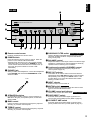
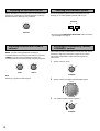
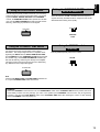
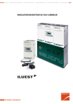
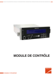
AX-492/592/892
Natural Sound Stereo Amplifier
Amplificateur stéréo de la série “Natural Sound”
Thank you for selecting this YAMAHA stereo amplifier.
Nous vous remercions d’avoir porté votre choix sur cet amplificateur stéréo YAMAHA.
OWNER’S MANUAL
MODE D’EMPLOI
SAFETY INSTRUCTIONS
7
Wall or Ceiling Mounting – The unit should be mounted to
a wall or ceiling only as recommended by the
manufacturer.
8
Ventilation – The unit should be situated so that its
location or position does not interfere with its proper
ventilation. For example, the unit should not be situated
on a bed, sofa, rug, or similar surface, that may block the
ventilation openings; or placed in a built-in installation,
such as a bookcase or cabinet that may impede the flow
of air through the ventilation openings.
9
Heat – The unit should be situated away from heat
sources such as radiators, stoves, or other appliances
that produce heat.
CAUTION
RISK OF ELECTRIC SHOCK
DO NOT OPEN
CAUTION: TO REDUCE THE RISK OF ELECTRIC SHOCK, DO NOT
REMOVE COVER (OR BACK). NO USER-SERVICEABLE PARTS INSIDE.
REFER SERVICING TO QUALIFIED SERVICE PERSONNEL.
• Explanation of Graphical Symbols
The lightning flash with arrowhead symbol, within an
equilateral triangle, is intended to alert you to the
presence of uninsulated “dangerous voltage” within the
product’s enclosure that may be of sufficient magnitude
to constitute a risk of electric shock to persons.
The exclamation point within an equilateral triangle is
intended to alert you to the presence of important
operating and maintenance (servicing) instructions in
the literature accompanying the appliance.
10 Power Sources – The unit should be connected to a
power supply only of the type described in the operating
instructions or as marked on the unit.
11 Power-Cord Protection – Power-supply cords should be
WARNING
TO REDUCE THE RISK OF FIRE OR ELECTRIC SHOCK, DO
NOT EXPOSE THIS UNIT TO RAIN OR MOISTURE.
routed so that they are not likely to be walked on or
pinched by items placed upon or against them, paying
particular attention to cords at plugs, convenience
receptacles, and the point where they exit from the unit.
IMPORTANT!
Please record the serial number of this unit in the space
below.
12 Cleaning – The unit should be cleaned only as
Model:
Serial No.:
13 Nonuse Periods – The power cord of the unit should be
The serial number is located on the rear of the unit.
Retain this Owner’s Manual in a safe place for future
reference.
recommended by the manufacturer.
unplugged from the outlet when left unused for a long
period of time.
14 Object and Liquid Entry – Care should be taken so that
objects do not fall into and liquids are not spilled into the
inside of the unit.
1
2
3
4
5
6
Read Instructions – All the safety and operating
instructions should be read before the unit is operated.
Retain Instructions – The safety and operating instructions
should be retained for future reference.
Heed Warnings – All warnings on the unit and in the
operating instructions should be adhered to.
Follow Instructions – All operating and other instructions
should be followed.
Water and Moisture – The unit should not be used near
water – for example, near a bathtub, washbowl, kitchen
sink, laundry tub, in a wet basement, or near a swimming
pool, etc.
Carts and Stands – The unit should be used only with a
cart or stand that is recommended by the
manufacturer.
6A A unit and cart combination should be
moved with care. Quick stops, excessive
force, and uneven surfaces may cause
the unit and cart combination to overturn.
2
15 Damage Requiring Service – The unit should be serviced
by qualified service personnel when:
A. The power-supply cord or the plug has been
damaged; or
B. Objects have fallen, or liquid has been spilled into the
unit; or
C. The unit has been exposed to rain; or
D. The unit does not appear to operate normally or
exhibits a marked change in performance; or
E. The unit has been dropped, or the cabinet damaged.
16 Servicing – The user should not attempt to service the unit
beyond those means described in the operating
instructions. All other servicing should be referred to
qualified service personnel.
17 Power Lines – An outdoor antenna should be located
away from power lines.
18 Grounding or Polarization – Precautions should be taken
so that the grounding or polarization is not defeated.
1. IMPORTANT NOTICE : DO NOT MODIFY THIS UNIT!
This product, when installed as indicated in the
instructions contained in this manual, meets FCC
requirements. Modifications not expressly approved by
Yamaha may void your authority, granted by the FCC, to
use the product.
2. IMPORTANT : When connecting this product to
accessories and/or another product use only high quality
shielded cables. Cable/s supplied with this product
MUST be used. Follow all installation instructions.
Failure to follow instructions could void your FCC
authorization to use this product in the USA.
3. NOTE : This product has been tested and found to
comply with the requirements listed in FCC Regulations,
Part 15 for Class “B” digital devices. Compliance with
these requirements provides a reasonable level of
assurance that your use of this product in a residential
environment will not result in harmful interference with
other electronic devices.
This equipment generates/uses radio frequencies and, if
not installed and used according to the instructions
found in the users manual, may cause interference
harmful to the operation of other electronic devices.
Compliance with FCC regulations does not guarantee that
interference will not occur in all installations. If this product
is found to be the source of interference, which can be
determined by turning the unit “OFF” and “ON”, please try
to eliminate the problem by using one of the following
measures:
English
FCC INFORMATION
Relocate either this product or the device that is being
affected by the interference.
Utilize power outlets that are on different branch (circuit
breaker or fuse) circuits or install AC line filter/s.
In the case of radio or TV interference, relocate/reorient the
antenna. If the antenna lead-in is 300 ohm ribbon lead,
change the lead-in to coaxial type cable.
If these corrective measures do not produce satisfactory
results, please contact the local retailer authorized to
distribute this type of product. If you can not locate the
appropriate retailer, please contact Yamaha Electronics
Corp., U.S.A. 6660 Orangethorpe Ave, Buena Park, CA
90620.
The above statements apply ONLY to those products
distributed by Yamaha Corporation of America or its
subsidiaries.
We Want You Listening For A Lifetime (for US customers only)
YAMAHA and the Electronic Industries Association’s
Consumer Electronics Group want you to get the most out of
your equipment by playing it at a safe level. One that lets the
sound come through loud and clear without annoying blaring
or distortion – and, most importantly, without affecting your
sensitive hearing.
Since hearing damage from loud sounds is often
undetectable until it is too late, YAMAHA and the
Electronic Industries Association’s Consumer
Electronics Group recommend you to avoid
prolonged exposure from excessive volume levels.
3
CONTENTS
FEATURES
Supplied accessories .....................................................4
Connections ...................................................................6
Controls and their functions ..........................................12
Remote control .............................................................14
Basic operations ...........................................................16
Troubleshooting ............................................................20
Specifications ...............................................................21
●
AX-492 85W + 85W (8Ω) RMS Output Power,
●
AX-592 100W + 100W (8Ω) RMS Output Power,
●
AX-892 115W + 115W (8Ω) RMS Output Power,
0.019% THD, 20–20,000 Hz
0.015% THD, 20–20,000 Hz
●
●
●
●
●
●
●
Supplied accessories
●
After unpacking, check that the following accessories are included.
●
Remote Control Transmitter
YAMAHA HiFi SYSTEM
REMOTE CONTROL TRANSMITTER
●
YAMAHA HiFi SYSTEM
REMOTE CONTROL TRANSMITTER
AUX
AUX
DIR A
DIR B REC/PAUSE
PLAY
TAPE 2
A/B
PRESET
A/B/C/D/E
DISC
PLAY
DIR A
DIR B REC/PAUSE
PLAY
A/B
TAPE 1
TUNER
PRESET
A/B/C/D/E
DISC
CD
PLAY
PLAY
/CUT PHONO
POWER
VOLUME
AX-592/892
4
0.015% THD, 20–20,000 Hz
High Dynamic Power, Low Impedance Drive Capability
Continuously Variable Loudness Control
CD DIRECT AMP switch: used to reproduce the purest
CD sound
PURE DIRECT switch: used to reproduce the purest
source sound
SUBSONIC FILTER switch; used to eliminate undesirable
ultra-low-frequency signals (AX-592 and AX-892 only)
PRE OUT/MAIN IN terminals; useful for connecting an
equalizer, sound processor, etc. (AX-592 and AX-892
only)
Remote control capability
TAPE 2
TAPE 1
TUNER
CD
PHONO
POWER
VOLUME
AX-492
Batteries (size AA, R6, UM-3)
1.
To assure the finest performance, please read this manual
carefully and keep it in a safe place for future use.
2.
Install this unit in a cool, dry and dust-free area. Do not place it in
direct sunlight or near sources of heat (e.g., a stove, etc.). Make
sure that it is well ventilated and not exposed to rain or moisture
and that it is on a flat, stable surface, free from vibration.
13.
Voltage Selector (General Model only)
The voltage selector on the rear panel of this unit must be set
for your local main voltage before plugging into the electrical
outlet.
Voltages are 110/120/220/240 V AC, 60/50 Hz.
WARNING
To reduce the risk of fire or electric shock, do not expose the unit to
rain or moisture.
3.
Never open the cabinet. If something drops into the unit, contact
your dealer.
4.
When moving the unit, first disconnect the AC power plug and the
cables which are connected to other equipment. Never pull the
cables or use excessive force on switches or controls.
The serial number is located on the rear panel.
Please record the serial number of this unit in the space below.
The openings on the cabinet assure proper ventilation of the unit.
If these openings are obstructed, the temperature inside the
cabinet will rise rapidly, damaging the unit or causing a fire. Avoid
blocking the ventilation openings and make sure that the unit is
well ventilated. Allow at least 30 cm (12 in) of space above the
unit and 20 cm (8 in) of space on the sides and rear.
Keep this Owner’s Manual in a safe place for future use.
5.
IMPORTANT
Serial No.:
Note
The unit is not disconnected from the AC power source as long as it
is connected to the electrical outlet, even if the unit itself is turned
off.
Always set the VOLUME control to “∞” before playing the source.
Increase the volume gradually to a desired level after the source
has started playing.
CAUTION (FOR CANADA MODEL)
7.
Use a clean, dry cloth to clean the unit. Do not use chemical
solvents which might damage the finish.
FOR CANADIAN CUSTOMERS
8.
Be sure to read the “TROUBLESHOOTING” section before
deciding that the unit is faulty.
9.
When not planning to use this unit for long periods of time (e.g.,
vacation, etc.), disconnect the AC power plug from the electrical
outlet.
10.
To prevent damage from lightning, disconnect the AC power plug
and antenna cable when there is an electrical storm.
11.
Make sure that the unit is always properly grounded and
polarized.
12.
Do not connect audio equipment to the AC outlet on the rear panel
if the equipment requires more power than the outlet is rated to
provide.
6.
WARNING
Do not change the IMPEDANCE SELECTOR
switch setting while the power to this unit is on,
otherwise this unit may be damaged.
IF THIS UNIT FAILS TO TURN ON WHEN THE
POWER SWITCH IS PRESSED
The IMPEDANCE SELECTOR switch may not be
set to either end closely. If so, set the switch to
either end closely.
English
CAUTION: READ THIS BEFORE OPERATING YOUR UNIT.
TO PREVENT ELECTRIC SHOCK, MATCH WIDE BLADE OF
PLUG TO WIDE SLOT AND FULLY INSERT.
THIS CLASS B DIGITAL APPARATUS MEETS ALL
REQUIREMENTS OF THE CANADIAN INTERFERENCECAUSING EQUIPMENT REGULATIONS.
IMPEDANCE
SELECTOR
VOLTAGE SELECTOR
AC OUTLETS
SWITCHIED
100W MAX. TOTAL
A OR B : 4Ω MIN. /SPEAKER
A + B : 8Ω MIN. /SPEAKER
A OR B : 6Ω MIN. /SPEAKER
A + B :12Ω MIN. /SPEAKER
Example: AX-892
<General model>
5
CONNECTIONS
●
●
●
Before making any connections to or from this unit, first switch it and any other connected components off.
Properly connect this unit and other components, L (left) to L, R (right) to R, “+” to “+” and “–” to “–”. Also, refer to the owner’s
manual of each component which is to be connected to this unit.
If you have YAMAHA components numbered 1, 2, 3, etc. on the rear panel, connections can easily be made by connecting the
output (input) terminals of each component to the same-numbered terminals on this unit.
AX-492
Right
LINE IN
LINE IN
Speakers A
Left
+
–
–
+
GND
OUTPUT
Tape deck 2
LINE OUT
Tape deck 1
LINE OUT
Turntable
PHONO
AC OUTLETS
VOLTAGE SELECTOR
L
R
GND
SWITCHIED
100W MAX. TOTAL
1 CD
L
R
R
L
L
R
2
TUNER
TAPE
PB
3
REC
OUT
4
TAPE
PB
TAPE 1
3
REC
OUT
TAPE 2
(MD)
A OR B : 4Ω MIN. /SPEAKER
A + B : 8Ω MIN. /SPEAKER
A OR B : 6Ω MIN. /SPEAKER
A + B :12Ω MIN. /SPEAKER
A
4
AUX
B
CAUTION SEE INSTRUCTION MANUAL FOR CONNECT SETTING
IMPEDANCE SELECTOR
<General model>
AUDIO OUT
OUTPUT
OUTPUT
SPEAKERS
To
electrical
outlet
+
–
–
Right
Compact disc player
Tuner
* For descriptions of the shaded areas, refer to page 10.
6
Video cassette player,
LD player, etc.
+
Left
Speakers B
English
AX-592
Right
LINE IN
LINE IN
Speakers A
PHONO
SPEAKERS
COUPLER
R
A
L
Left
–
OUTPUT
GND
Tape deck 2
LINE OUT
Tape deck 1
LINE OUT
Turntable
+
–
+
IMPEDANCE
SELECTOR
L
L
R
R
MM
MC
PRE
OUT
MAIN
IN
VOLTAGE SELECTOR
L
R
L
A OR B : 4Ω MIN. /SPEAKER
A + B : 8Ω MIN. /SPEAKER
L
R
GND
CAUTION SEE INSTRUCTION MANUAL FOR CONNECT SETTING
R
1 CD
2
TUNER
TAPE
PB
3
REC
OUT
TAPE 1
4
TAPE
PB
3
REC
OUT
TAPE 2
(MD)
A OR B : 6Ω MIN. /SPEAKER
A + B :12Ω MIN. /SPEAKER
4
AUX
B
PHONO
100W MAX. TOTAL
SWITCHIED
AC OUTLETS
<General model>
AUDIO OUT
OUTPUT
OUTPUT
REMOTE
CONTROL
To
electrical
outlet
+
–
–
Left
Right
Compact disc player
Tuner
Video cassette player,
LD player, etc.
+
Speakers B
* For descriptions of the shaded areas, refer to page 10.
7
AX-892
Right
LINE IN
LINE IN
Speakers A
Left
–
+
–
+
OUTPUT
GND
Tape deck 2
LINE OUT
Tape deck 1
LINE OUT
Turntable
COUPLER
PHONO
PRE
OUT
R
SPEAKERS
CAUTION SEE INSTRUCTION MANUAL FOR CONNECT SETTING
MAIN
IN
L
IMPEDANCE
SELECTOR
VOLTAGE SELECTOR
A
L
L
R
R
MM
MC
L
R
B
L
R
R
1 CD
2
TAPE
PB
TUNER
3
REC
OUT
4
TAPE
PB
TAPE 1
3
REC
OUT
TAPE 2
(MD)
AC OUTLETS
SWITCHIED
100W MAX. TOTAL
L
A OR B : 4Ω MIN. /SPEAKER
A + B : 8Ω MIN. /SPEAKER
A OR B : 6Ω MIN. /SPEAKER
A + B :12Ω MIN. /SPEAKER
4
AUX
GND
REMOTE
CONTROL
PHONO
AUDIO OUT
OUTPUT
OUTPUT
<General model>
To
electrical
outlet
–
+
–
Right
Compact disc player
Tuner
* For descriptions of the shaded areas, refer to page 10.
8
Video cassette player,
LD player, etc.
+
Left
Speakers B
Connect the SPEAKERS terminals to your speakers with cable
of the proper gauge, cut as short as possible. If the speakers
are improperly connected, no sound will be heard. Connect
each speaker making sure that the polarity (+ and –) is correct.
●
●
One or two speaker systems can be connected to this unit.
If you connect only one speaker system, connect it to either
SPEAKERS A or B terminals.
Use speakers with the specified impedance shown on the
rear panel.
English
CONNECTING SPEAKERS
Red: positive (+)
Black: negative (–)
If the cables are reversed, the sound will be unnatural and will
lack bass. Do not allow exposed wires to touch each other
or metal parts; this could damage the unit and speakers.
For AX-492’s SPEAKERS A and B terminals and
for AX-592’s SPEAKERS B terminals only:
➀ Unscrew the knob.
➁ Insert the exposed wire.
[Remove approx. 5 mm
(1/4 in) insulation from
the speaker wires.]
➂ Tighten the knob and
secure the wire.
1
For AX-592’s SPEAKERS A terminals only and
for AX-892’s SPEAKERS A and B terminals:
2
2
3
Banana plug connections are also possible. Simply insert the
banana plug connector into the corresponding terminal.
(except for UK and Europe models)
1
3
➀ Unscrew the knob.
➁ Insert the exposed wire.
[Remove approx. 5 mm (1/4
in) insulation from the
speaker wires.]
➂ Tighten the knob and secure
the wire.
REAR PANEL PARTS
AC OUTLETS (SWITCHED)
Use these to connect the power cords from your components
to this unit.
The power to the SWITCHED outlets is controlled by this unit’s
POWER switch or the remote control’s POWER key. These
outlets will supply power to the connected components
whenever this unit is turned on.
The maximum power (total power consumption of
components) that can be connected to the AC OUTLETS
(SWITCHED) is 100 watts.
9
GND terminal (for turntable use)
PRE OUT/MAIN IN terminals
Connecting the ground wire of the turntable to this terminal will
normally minimize hum, but in some cases better results may
be obtained with the ground wire disconnected.
Removing the jumper pins enables this unit to independently
perform the functions of a control amplifier and a power
amplifier. These terminals are for connection of a signalprocessing system such as a graphic equalizer or sound
processor.
If a sound processor or other external unit is connected
between these terminals, the VOLUME control of this unit can
be used for overall adjustment of the sound level.
To connect such a unit, remove the jumper pins from the PRE
OUT/MAIN IN terminals, connect the inputs of that unit to the
PRE OUT terminals and its outputs to the MAIN IN terminals.
For details, refer to the owner’s manual included with the unit to
be connected.
REMOTE CONTROL (PHONO) connector
AX-592 and AX-892 only
If you have a YAMAHA turntable with a terminal for remote
control, connect it to this connector using the cable provided
with the turntable. This connection allows you to control the
turntable with the remote control.
AX-592 and AX-892 only
COUP
PRE
OUT
REMOTE
CONTROL
LER
MAIN
IN
L
R
PHONO
PHONO
REMOTE
CONTROL
(AX-592)
(AX-892)
PHONO (MM/MC) switch
Note
AX-592 and AX-892 only
Select either MM or MC depending on your phono cartridge. If
you use a high-output MC cartridge, select MM. To select MC,
press the switch so that it stays in. To select MM, press the
switch again, so that it releases.
MM
MC
10
●
●
●
If you will not use the PRE OUT/MAIN IN terminals, never
remove the jumper pins. If removed, no sound will be
output from this unit.
If you will use this unit with an external unit connected
between the PRE OUT and MAIN IN terminals, make sure
that the CD DIRECT AMP and PURE DIRECT switches on
the front panel are turned off.
If you will use this unit as a power amplifier, connect the
outputs of an external control amplifier, etc. to this unit’s
MAIN IN terminals. In this case, this unit’s controls will not
function, except the PHONES jack and the SPEAKERS
switches, so use the controls on the external control
amplifier to make volume adjustment, etc.
VOLTAGE SELECTOR switch (General model only)
Make sure that the power to the unit is off, before you set the
switch.
Select the appropriate setting for your speaker system.
If the pre-set setting is incorrect, set the switch to the proper
voltage for your area.
Upper position
English
IMPEDANCE SELECTOR switch
Consult your dealer if you are unsure of the correct setting.
WARNING
4 Ω: If you use either speaker system A or B, the impedance
of each speaker must be 4 Ω, or higher.
8 Ω: If you use both speaker systems A and B at the same
time, the impedance of each speaker must be 8 Ω, or
higher.
Be sure to unplug the unit before setting the VOLTAGE
SELECTOR switch.
240V
Lower position
6 Ω: If you use either speaker system A or B, the impedance
of each speaker must be 6 Ω, or higher.
12 Ω:If you use both speaker systems A and B at the same
time, the impedance of each speaker must be 12 Ω, or
higher.
A OR B : 4Ω MIN. /SPEAKER
A + B : 8Ω MIN. /SPEAKER
A OR B : 6Ω MIN. /SPEAKER
A + B :12Ω MIN. /SPEAKER
WARNING
Do not change the IMPEDANCE SELECTOR switch
setting while the power to this unit is on, otherwise
this unit may be damaged.
IF THIS UNIT FAILS TO TURN ON WHEN THE POWER
SWITCH IS PRESSED
The IMPEDANCE SELECTOR switch may not be set to
either end closely. If so, set the switch to either end
closely.
11
CONTROLS AND THEIR FUNCTIONS
FRONT PANEL
AX-492
E
NATURAL SOUND STEREO AMPLIFIER AX-492
CD DIRECT AMP
PURE DIRECT
INPUT
VOLUME
D
1
16
20
CD
TAPE 1
POWER
1
2
0
1
1
2
2
3
3
4
4
–5
0
1
1
2
BASS
3
4
4
–5
2
3
3
4
5+
1
1
2
2
3
0
4
L5
5+
TREBLE
TAPE 1
-30db
10
2
3
9
4
CD
TUNER
TAPE 2
(MD)
AUX
12
TUNER
TAPE 2
(MD)
PHONO
28
8
PHONO
40
AUX
4
8
5
5R
BALANCE
FLAT
6
C
7
60
LOUDNESS
2
REC OUT
∞
0
-db
PHONES
3
SPEAKERS
A
B
ON
OFF
4
5
6
8
9
0
A
AX-592
E
NATURAL SOUND STEREO AMPLIFIER AX-592
CD DIRECT AMP
PURE DIRECT
INPUT
VOLUME
D
1
16
20
CD
TAPE 1
POWER
1
2
0
1
1
2
2
3
3
4
4
–5
5+
BASS
0
1
1
2
2
3
ON
OFF
2
3
4
L5
5+
TREBLE
2
4
4
–5
1
1
3
3
4
0
SUBSONIC
FILTER
5R
BALANCE
FLAT
TAPE 1
-30db
10
2
3
9
4
CD
TUNER
TAPE 2
(MD)
AUX
12
TUNER
TAPE 2
(MD)
PHONO
28
8
PHONO
40
AUX
4
8
5
6
7
LOUDNESS
60
2
REC OUT
∞
0
-db
PHONES
3
SPEAKERS
A
B
ON
OFF
4
12
5
6
7
8
9
0
A
C
English
AX-892
E
NATURAL SOUND STEREO AMPLIFIER AX-892
CD DIRECT AMP
PURE DIRECT
INPUT
VOLUME
D
1
16
20
CD
TAPE 1
2
POWER
1
0
1
2
1
2
3
3
4
4
–5
5+
BASS
0
1
2
1
2
3
ON
OFF
3
4
1
2
2
3
4
5+
TREBLE
1
3
4
–5
0
4
L5
SUBSONIC
FILTER
FLAT
TAPE 1
-30db
10
2
3
9
4
5R
CD
TUNER
TAPE 2
(MD)
AUX
12
TUNER
TAPE 2
(MD)
28
PHONO
8
PHONO
40
AUX
4
8
5
6
60
BALANCE
C
7
LOUDNESS
2
REC OUT
∞
0
-db
PHONES
3
SPEAKERS
B
A
ON
MUTING
OFF
4
ON
5
6
7
8
9
1 Remote control sensor
Receives signals from the remote control.
2 POWER switch
Press this switch to turn the power on and off. When the
power is on, the indicator will be illuminated.
*Standby mode <Except for U.S.A. and Canada models>
While the power is on, pressing the POWER key on the
remote control switches the unit to the standby mode. (In
this mode, the power indicator on the unit is halfilluminated.)
3 PHONES jack
When you listen with headphones, connect the headphones
to the PHONES jack and set both SPEAKERS A and B
switches to OFF.
PHONES
0
OFF
B
A
7 SUBSONIC FILTER switch
AX-592 and AX-892 only
Used to eliminate undesirable ultra-low-frequency signals
caused by turntable rumble or warped records without
losing sound quality.
8 BALANCE control
Adjusts the balance of the output volume to the left and right
speakers to compensate for channel imbalance caused by
speaker location or listening room conditions.
9 Continuously variable LOUDNESS control
Used to boost high and low-frequency ranges at low
volume. (Refer to page 18.)
0 REC OUT selector
This switch can be used to select a source and send its
signal directly to the REC OUT terminals on the rear panel,
independently of the setting of the INPUT selector. This
function allows you to record the selected source while
listening to another source.
A INPUT selector
Selects an input source to listen to.
B MUTING switch
AX-892 only
Press this switch to temporarily reduce the volume. Press
again to cancel the MUTING function.
C VOLUME control and indicator
Used to raise or lower the volume level. AX-592 and AX-892 only
4 SPEAKERS switches
For the desired speaker system(s), set the switch(es) to
ON. When using only one speaker system, set the other
switch to OFF.
5 BASS control
Used to increase or decrease the low-frequency response.
Selecting “0” produces a flat response.
D PURE DIRECT switch
Press this switch (the indicator lights up) to listen to a
source in the purest possible sound. (Refer to page 19.)
E CD DIRECT AMP switch
Press this switch (the indicator lights up) to listen in the
purest possible sound from your CD. (Refer to page 19.)
6 TREBLE control
Used to increase or decrease the high-frequency response.
Selecting “0” produces a flat response.
13
REMOTE CONTROL
The remote control provided with this unit is designed to control all the most commonly used functions of the unit. If the CD player,
tuner, turntable and tape deck connected to this unit are YAMAHA components designed for remote control compatibility, then this
remote control will also control the various functions of those components.
KEY FUNCTIONS
To control this unit
1 Input selector keys
Select an input source.
YAMAHA HiFi SYSTEM
REMOTE CONTROL TRANSMITTER
2 VOLUME +/– keys
Adjust the volume level.
AUX
DIR A
DIR B REC/PAUSE
1
2
PLAY
A/B
PRESET
PLAY
3
VOLUME
1
CD
PLAY
/CUT
POWER
TAPE 1
TUNER
A/B/C/D/E
DISC
3 POWER key
TAPE 2
PHONO
4
2
3
Turns the power on and off.
<Except for U.S.A. and Canada models>
While the power is on, pressing the POWER key on the
remote control switches the unit from the power-on mode
to the standby mode and vice versa. (In this mode, the
power indicator on the unit is half-illuminated.)
To control other components
Identify the remote control keys with your component’s keys. If
the keys are identical, the functions will be the same. If the keys
are different, refer to the component’s manual for their functions.
1 Tape deck keys
Control the tape deck.
DIR A, DIR B, and A/B are applicable only for a dual
tape deck.
● For a single tape deck with an automatic reverse
function, pressing DIR A will reverse the direction of the
tape.
●
2 Tuner
keys
Control the tuner.
+: Selects a higher preset station number.
–: Selects a lower preset station number.
A/B/C/D/E: Selects a group (A-E) of preset stations.
* The AX-492’s remote control does not have a PLAY/CUT
key.
3 CD player keys
Control the compact disc player.
DISC is applicable only for a compact disc changer.
●
4 PLAY/CUT key
AX-592 and AX-892 only
Press PLAY/CUT to lower the pick-up arm and press it
again to raise the arm.
14
English
Battery installation
Remote control operation range
2
1
Remote control
sensor
3
Within approximately
6 m (19.7 feet)
30°
Battery replacement
30°
If you find that the remote control must be used closer to the
unit, the batteries are weak. Replace both batteries with new
ones.
Note
●
●
●
●
Use only AA, R6, UM-3 batteries for replacement.
Be sure the polarities are correct. (See the illustration inside
the battery compartment.)
Remove the batteries if the remote control will not be used
for an extended period of time.
If batteries leak, dispose of them immediately. Avoid
touching the leaked material or letting it come in contact with
clothing, etc. Clean the battery compartment thoroughly
before installing new batteries.
Note
●
●
There should be no large obstacles between the remote
control and the unit.
If the remote control sensor is directly illuminated by strong
lighting (especially an inverter type of fluorescent lamp etc.),
it might prevent the remote control from working. In this
case, reposition the unit to avoid direct lighting.
Opening and closing the control door
When using the remote control or when it is not necessary to operate controls inside the control door, close it.
To open the door
To close the door
15
BASIC OPERATIONS
CD DIRECT AMP
NATURAL SOUND STEREO AMPLIFIER AX-892
PURE DIRECT
INPUT
VOLUME
16
20
CD
TAPE 1
2
POWER
1
0
1
2
1
2
3
3
4
4
–5
5+
BASS
0
1
2
1
2
3
ON
OFF
3
4
1
2
3
4
5+
TREBLE
1
2
3
4
–5
0
4
L5
SUBSONIC
FILTER
5R
FLAT
TAPE 1
-30db
10
2
3
9
4
CD
TUNER
TAPE 2
(MD)
AUX
12
TUNER
TAPE 2
(MD)
PHONO
28
40
AUX
4
8
5
6
7
60
BALANCE
1,6
8
PHONO
LOUDNESS
2
REC OUT
∞
0
-db
PHONES
SPEAKERS
A
B
ON
MUTING
OFF
ON
OFF
(AX-892)
4
7
3
* The AX-492 does not have a SUBSONIC FILTER and MUTING switch.
* The AX-592 does not have a MUTING switch.
PLAYING A SOURCE
1
∞”.
4
Turn the control to “
Select the speakers to be used.
VOLUME
SPEAKERS
B
A
16
20
12
28
8
ON
40
60
2
∞
* Be sure that the IMPEDANCE SELECTOR switch is
correctly set as explained on page 11.
* If you use two speaker systems, press both the A and B
switches to ON.
* If you listen with headphones, press both the A and B
switches to OFF.
0
-db
2
Turn the power on.
POWER
3
OFF
4
5
Play the source.
6
Adjust the volume to the desired level.
VOLUME
Select the desired input source.
16
20
INPUT
12
28
40
CD
TAPE 1
8
4
TUNER
60
TAPE 2
(MD)
2
PHONO
∞
0
-db
AUX
AX-592 and AX-892 only
* If you select PHONO as an input source, you should make
sure that PHONO (MM/MC) is switched to the correct
position. (Refer to page 10.)
16
7
If needed, adjust the BASS, TREBLE, BALANCE
LOUDNESS, etc. controls. (Refer to page 18.)
Note
To turn off the power, press the POWER switch again.
English
CD DIRECT AMP
NATURAL SOUND STEREO AMPLIFIER AX-892
PURE DIRECT
INPUT
VOLUME
16
20
CD
TAPE 1
POWER
0
1
1
1
2
2
1
OFF
0
1
1
2
2
3
3
3
4
–5
BASS
ON
2
4
5+
–5
1
3
4
4
0
2
3
3
4
4
5+
L5
SUBSONIC
FILTER
TREBLE
5R
FLAT
TAPE 1
-30db
10
2
9
3
CD
TUNER
TAPE 2
(MD)
AUX
TAPE 2
(MD)
12
TUNER
PHONO
28
8
PHONO
40
AUX
4
8
4
5
6
7
60
BALANCE
LOUDNESS
2
3
REC OUT
∞
0
-db
SPEAKERS
A
B
PHONES
ON
MUTING
OFF
ON
OFF
(AX-892)
1
3,5
* The AX-492 does not have a SUBSONIC FILTER and MUTING switch.
* The AX-592 does not have a MUTING switch.
RECORDING A SOURCE TO A TAPE (OR DUBBING FROM TAPE TO TAPE)
1
REC OUT selector setting for dubbing tape to tape
Select the source to be recorded.
TAPE 1
CD
To tape from tape deck 1 to
tape deck 2.
TUNER
TAPE 2
(MD)
AUX
To tape from tape deck 2 to
tape deck 1.
PHONO
TAPE 1
CD
TUNER
TAPE 2
(MD)
AUX
PHONO
TAPE 1
CD
TUNER
TAPE 2
(MD)
AUX
PHONO
REC OUT
2
3
Play the source.
REC OUT
Select the source with the INPUT selector and use the
VOLUME control to make sure that the proper source
is selected.
VOLUME
INPUT
16
20
CD
TAPE 1
TAPE 2
(MD)
12
TUNER
28
PHONO
8
40
AUX
REC OUT
Note
● If you want to listen to another source while recording,
select it with the INPUT selector.
● VOLUME, BASS, TREBLE, BALANCE, and LOUDNESS
controls and CD DIRECT AMP, PURE DIRECT,
SUBSONIC FILTER (AX-592 and AX-892 only) and the
MUTING switch (AX-892 only) have no effect on the
material being recorded.
4
60
2
∞
0
-db
4
5
Set the tape deck used for recording in the recording
mode.
To monitor the sound of the recording, select the tape
deck being used for recording.
INPUT
CD
TAPE 1
TAPE 2
(MD)
TUNER
PHONO
AUX
17
Adjusting the BALANCE control
Adjusts the balance of the output volume to the left and right
speakers to compensate for channel imbalance caused by
speaker location or listening room conditions.
1
0
Selecting the SPEAKER system
One or two speaker systems can be connected to this unit,
allowing you to select speaker system A or B, or both.
SPEAKERS
B
A
1
2
2
3
3
4
4
L5
ON
5R
OFF
BALANCE
* Be sure that the INPEDANCE SELECTOR switch is correctly
set as explained on page 11.
Adjusting the BASS and TREBLE
controls
BASS: Turn this control clockwise to increase (or
counterclockwise to decrease) the low-frequency response.
TREBLE: Turn this control clockwise to increase (or
counterclockwise to decrease) the high-frequency response.
1
0
2
1
1
2
3
3
4
4
–5
5+
0
Adjusting the continuously variable
LOUDNESS control
This control provides compensation for the human ears’ loss of
sensitivity to high and low-frequency ranges at low volume.
This control is adjustable to retain full tonal range at any
volume level.
1
Set the control to “FLAT”.
1
2
2
3
1
3
4
4
–5
-30db
10
3
5+
9
4
8
5
BASS
FLAT
2
TREBLE
6
7
LOUDNESS
Note
Selecting “0” produces a flat response.
2
Set the volume to the highest desired listening level.
VOLUME
16
20
12
28
8
40
4
60
2
∞
0
-db
3
Turn until the desired volume is gained.
1
FLAT
-30db
10
2
3
9
4
8
5
6
7
LOUDNESS
18
Setting the SUBSONIC FILTER switch
AX-592 and AX-892 only
You can enjoy the purest possible sound from your sources by
setting this switch so that the indicator illuminates. The signals
bypass the BASS, TREBLE, BALANCE and LOUDNESS
controls, the SUBSONIC FILTER switch (AX-592 and AX-892
only), and the PRE OUT/MAIN IN terminals (AX-592 and AX892 only), eliminating any alterations to the signals.
English
Using the PURE DIRECT switch
When this switch is set ON, undesirable ultra-low-frequency
signals caused by turntable rumble or warped records can be
eliminated without losing sound quality.
ON
OFF
PURE DIRECT
SUBSONIC
FILTER
Using the CD DIRECT AMP switch
Using the MUTING switch
AX-892 only
For the best CD sound, set this switch so the indicator
illuminates. The CD input signal is sent to a separate circuit,
bypassing the INPUT selector, BASS, TREBLE, BALANCE
and LOUDNESS controls, SUBSONIC FILTER switch (AX-592
and AX-892 only), and the PRE OUT/MAIN IN terminals (AX592 and AX-892 only) and then goes directly to the amplifier.
This signal routing ensures the purest CD sound, eliminating
any alterations to the original CD signals.
Selecting ON temporarily reduces the volume.
MUTING
ON
OFF
CD DIRECT AMP
Note
If both the CD DIRECT AMP and PURE DIRECT switches are
on, only the CD DIRECT AMP switch will function.
WARNING
When the LOUDNESS control has been set, if the PURE DIRECT switch or the CD DIRECT AMP switch is pressed, the sound
will suddenly increase and may damage your ears or the speaker (the LOUDNESS control function may be bypassed).
Therefore, only press the PURE DIRECT switch or the CD DIRECT AMP switch after lowering the volume or after checking
that the LOUDNESS control is properly set.
19
TROUBLESHOOTING
If the unit fails to operate normally, check the following points to determine whether the fault can be corrected by the simple
measures suggested. If it cannot be corrected, or if the fault is not listed in the SYMPTOM column, disconnect the AC power plug
and contact your authorized YAMAHA dealer or service center for help.
SYMPTOM
The unit fails to turn on when the POWER
switch is pressed, or turns off suddenly
soon after the power is turned on.
No sound.
CAUSE
The AC power plug is not plugged in or is not
completely inserted.
The IMPEDANCE SELECTOR switch on the
rear panel is not set to the upper or the lower
end exactly.
Incorrect output cable connections.
The appropriate input source is not selected.
Sound level is too low.
The sound suddenly goes off.
Only one speaker outputs sound.
There is a lack of bass and no ambience.
The sound “hums”.
Sound level is low or sound is distorted
while playing a record on the turntable.
The volume level cannot be increased, or
sound is distorted.
Using the BASS, TREBLE, BALANCE, and
LOUDNESS controls and SUBSONIC
FILTER switch (AX-592 and AX-892 only)
does not affect the tone.
The input source can not be changed,
though the INPUT selector is turned.
The remote control does not work.
The distance or range within which the
remote control can be used decreases.
The sound is degraded when listening with
the headphones connected to the compact
disc player or cassette deck that are
connected with this unit.
20
The SPEAKERS switches are not set
properly.
Speaker connections are not secure.
The jumpor pins (PRE OUT/MAIN IN) are not
connected properly. (AX-592 and AX-892 only)
The MUTING switch is pushed in. (Muting is
on) (AX-892 only)
The protection circuit has been activated
because of a short circuit, etc.
Incorrect setting of the BALANCE control.
Incorrect cable connections.
The cable polarity is reversed at the amplifier
or speakers.
Incorrect cable connections.
No connection from the turntable to the GND
terminal.
The LOUDNESS control is functioning.
The PHONO (MM/MC) switch is set to the
improper position (AX-592 and AX-892 only).
The power to the component connected to the
REC OUT terminals of this unit is off.
The CD DIRECT AMP or PURE DIRECT
switch is on.
REMEDY
Firmly plug in the AC power plug.
Set the switch to the upper or the lower end
exactly.
Connect the cables properly. If the problem
persists, the cables may be defective.
Select an appropriate input source with the
INPUT selector.
Set the SPEAKERS switch, which corresponds
to the speakers to be used, to ON.
Secure the connections.
Connect the jumper pins properly.
(AX-592 and AX-892 only)
Push the MUTING switch again. (Muting is off)
(AX-892 only)
Turning the unit off and then on will reset the
protection circuit.
Adjust it to the appropriate position.
Connect the cables properly. If the problem
persists, the cables may be defective.
Connect the speaker cables correctly.
Firmly connect the cables. If the problem
persists, the cables may be defective.
Make the GND connection between the
turntable and this unit.
Set the LOUDNESS control to the FLAT
position.
Set the PHONO (MM/MC) switch to the proper
position (AX-592 and AX-892 only).
Turn the power to the component on.
The CD DIRECT AMP and PURE DIRECT
switches must be switched off to use those
controls.
The CD DIRECT AMP switch is on.
Switch off the CD DIRECT AMP switch.
Direct sunlight or lighting (of an inverter type of
fluorescent lamp etc.) is striking the remote
control sensor of the unit.
The batteries of the remote control are too
weak.
The power to this unit is off.
Change the position of the unit.
Replace the batteries with new ones.
Turn the power to this unit on.
AUDIO SECTION
Minimum RMS Output Power per Channel
8 ohms, 20 Hz to 20 kHz, 0.019% THD
...................................................85W+85W
6 ohms, 20 Hz to 20 kHz, 0.038% THD
...............................................100W+100W
Dynamic Power per Channel
(by IHF Dynamic Headroom measuring
method)
8/6/4/2 ohms ...................130/150/185/220W
DIN Standard Output Power per Channel
[Europe model only]
(4 ohms, 1 kHz, 0.7% THD) ..............120W
Output Level/Impedance
REC OUT .......................150 mV/0.6 k-ohms
Headphone Jack Rated Output/ Impedance
Output Level (8 ohms, 0.019% THD)
...............................................................0.3V
Impedance.....................................680 ohms
Frequency Response (20 Hz to 20 kHz)
CD/TUNER/TAPE/AUX ....................0±0.5 dB
Tone Control Characteristics
BASS: Boost/cut ................±10 dB (20 Hz)
Turnover Frequency.........(350 Hz)
TREBLE: Boost/cut...........±10 dB (20 kHz)
Turnover Frequency.....(3.5 kHz)
Continuous Loudness Control
Attenuation ............................–30 dB (1 kHz)
(Level related equalization)
Gain Tracking Error (0 to –60 dB) ............2 dB
RIAA Equalization Deviation
PHONO...........................................0±0.3 dB
GENERAL
Power Supply
[Europe and U.K. models] ...AC 230V, 50 Hz
[General model]
..................AC 110/120/220/240V, 60/50 Hz
IEC Power [Europe model only]
(8 ohms, 1 kHz, 0.019% THD) .............100W
Total Harmonic Distortion (20 Hz to 20 kHz)
PHONO to REC OUT (3V) ................0.003%
CD/TUNER/TAPE/AUX to SP OUT
(42.5W/8 ohms) ................................0.008%
Power Band Width
8 ohms, 42.5W, 0.038% THD
.............................................10 Hz to 50 kHz
Signal-to-Noise Ratio (IHF-A Network)
PHONO (5 mV Input Shorted) ............ 88 dB
CD (CD DIRECT AMP ON, Shorted)... 110 dB
Damping Factor SP-A
8 ohms, 20 Hz–20 kHz ..............240 or more
Residual Noise (IHF-A Network)
CD (CD DIRECT AMP ON) ...................35 µV
PURE DIRECT ON ..............................90 µV
AC Outlets
[Europe and General models]
3 SWITCHED OUTLETS ..100W max. total
[U.K. model]
1 SWITCHED OUTLET ....100W max. total
Channel Separation
CD/TUNER/TAPE/AUX (Input 5.1 k-ohms
Terminated 1 kHz/10 kHz).........65 dB/50 dB
Dimensions (W x H x D)
......................................435 x 151 x 391 mm
(17-1/8” x 6.0” x 15-3/8”)
Maximum Output Power (EIAJ)
[General model only]
8 ohms, 1 kHz, 10% THD .................130W
6 ohms, 1 kHz, 10% THD .................150W
Input Sensitivity/Impedance
PHONO ............................2.5 mV/47 k-ohms
CD/TUNER/TAPE/AUX ....150 mV/47 k-ohms
English
SPECIFICATIONS (AX-492)
Power Consumption ...............................210W
Weight .............................9.6 kg (21 lbs. 1 oz.)
Accessories ...........Remote control transmitter
Batteries
Maximum Input Signal (1 kHz, 0.003% THD)
PHONO.............................................115 mV
Specifications subject to change without
notice.
21
SPECIFICATIONS (AX-592)
AUDIO SECTION
Minimum RMS Output Power per Channel
8 ohms, 20 Hz to 20 kHz, 0.015% THD
...............................................100W+100W
6 ohms, 20 Hz to 20 kHz, 0.03% THD
...............................................120W+120W
Dynamic Power per Channel
(by IHF Dynamic Headroom measuring
method)
8/6/4/2 ohms ...................140/170/220/290W
DIN Standard Output Power per Channel
[Europe model only]
(4 ohms, 1 kHz, 0.7% THD) ..............155W
IEC Power [Europe model only]
(8 ohms, 1 kHz, 0.015% THD) .............110W
Power Band Width
8 ohms, 50W, 0.03% THD
.............................................10 Hz to 50 kHz
Damping Factor SP-A
8 ohms, 20 Hz–20 kHz ..............320 or more
Maximum Output Power (EIAJ)
[General model only]
8 ohms, 1 kHz, 10% THD .................145W
6 ohms, 1 kHz, 10% THD .................170W
Input Sensitivity/Impedance
PHONO MM .....................2.5 mV/47 k-ohms
PHONO MC ......................160 µV/250 ohms
CD/TUNER/TAPE/AUX ....150 mV/47 k-ohms
MAIN IN .................................1 V/30 k-ohms
Maximum Input Signal (1 kHz, 0.007% THD)
PHONO MM......................................150 mV
PHONO MC ........................................10 mV
Output Level/Impedance
REC OUT .......................150 mV/0.6 k-ohms
PRE OUT ..............................1 V/1.2 k-ohms
Headphone Jack Rated Output/ Impedance
Output Level (8 ohms, 0.015% THD)
.............................................................0.33V
Impedance.....................................680 ohms
Tone Control Characteristics
BASS: Boost/cut ................±10 dB (20 Hz)
Turnover Frequency.........(350 Hz)
TREBLE: Boost/cut...........±10 dB (20 kHz)
Turnover Frequency.....(3.5 kHz)
Filter Characterristics
SUBSONIC FILTER .........15 Hz, –18 dB/oct
Frequency Response (20 Hz to 20 kHz)
CD/TUNER/TAPE/AUX ....................0±0.5 dB
MAIN IN...........................................0±0.5 dB
Continuous Loudness Control
Attenuation ............................–30 dB (1 kHz)
(Level related equalization)
RIAA Equalization Deviation
PHONO MM....................................0±0.3 dB
PHONO MC ....................................0±0.5 dB
Gain Tracking Error (0 to –60 dB) ............2 dB
Total Harmonic Distortion (20 Hz to 20 kHz)
PHONO MM to REC OUT (3V) .........0.003%
PHONO MC to REC OUT (3V) .........0.007%
CD/TUNER/TAPE/AUX to PRE OUT (1 V)
..........................................................0.005%
CD/TUNER/TAPE/AUX to SP OUT
(50W/8 ohms) ...................................0.008%
Signal-to-Noise Ratio (IHF-A Network)
PHONO MM (5 mV Input Shorted) ..... 92 dB
PHONO MC (500 µV Input Shorted)... 76 dB
CD (CD DIRECT AMP ON Shorted) ... 110 dB
GENERAL
Power Supply
[U.S.A. and Canada models]
...........................................AC 120 V, 60 Hz
[Australia model].................AC 240 V, 50 Hz
[Europe and U.K. models] ..AC 230 V, 50 Hz
[General model]
..................AC 110/120/220/240V, 60/50 Hz
Power Consumption ...............................220W
[U.S.A model only] ...............................200W
Residual Noise (IHF-A Network)
CD (CD DIRECT AMP ON) ...................35 µV
PURE DIRECT ON ............................. 90 µV
AC Outlets
[U.S.A., Europe, Canada and General models]
3 SWITCHED OUTLETS ..100W max. total
[Australia and U.K. models]
1 SWITCHED OUTLET ....100W max. total
Channel Separation
CD/TUNER/TAPE/AUX (Input 5.1 k-ohms
Terminated 1 kHz/10 kHz).........65 dB/50 dB
Dimensions (W x H x D)
......................................435 x 151 x 396 mm
(17-1/8” x 6.0” x 15-1/2”)
Weight ...........................10.6 kg (23 lbs. 4 oz.)
Accessories ...........Remote control transmitter
Batteries
Specifications subject to change without
notice.
22
AUDIO SECTION
Minimum RMS Output Power per Channel
8 ohms, 20 Hz to 20 kHz, 0.015% THD
...............................................115W+115W
6 ohms, 20 Hz to 20 kHz, 0.03% THD
...............................................140W+140W
Dynamic Power per Channel
(by IHF Dynamic Headroom measuring
method)
8/6/4/2 ohms ...................150/200/250/330W
DIN Standard Output Power per Channel
[Europe model only]
(4 ohms, 1 kHz, 0.7% THD) ..............190W
IEC Power [Europe model only]
(8 ohms, 1 kHz, 0.015% THD) .............125W
Power Band Width
8 ohms, 57.5W, 0.03% THD
.............................................10 Hz to 50 kHz
Damping Factor SP-A
8 ohms, 20 Hz–20 kHz ..............320 or more
Maximum Output Power (EIAJ)
[General model only]
8 ohms, 1 kHz, 10% THD .................160W
6 ohms, 1 kHz, 10% THD .................190W
Input Sensitivity/Impedance
PHONO MM .....................2.5 mV/47 k-ohms
PHONO MC ......................160 µV/250 ohms
CD/TUNER/TAPE/AUX ....150 mV/47 k-ohms
MAIN IN .................................1 V/30 k-ohms
Maximum Input Signal (1 kHz, 0.007% THD)
PHONO MM......................................150 mV
PHONO MC ........................................10 mV
Output Level/Impedance
REC OUT .......................150 mV/0.6 k-ohms
PRE OUT ..............................1 V/1.2 k-ohms
Headphone Jack Rated Output/ Impedance
Output Level (8 ohms, 0.015% THD)
.............................................................0.35V
Impedance.....................................680 ohms
Tone Control Characteristics
BASS: Boost/cut ................±10 dB (20 Hz)
Turnover Frequency.........(350 Hz)
TREBLE: Boost/cut...........±10 dB (20 kHz)
Turnover Frequency.....(3.5 kHz)
Filter Characterristics
SUBSONIC FILTER .........15 Hz, –18 dB/oct
Frequency Response (20 Hz to 20 kHz)
CD/TUNER/TAPE/AUX ....................0±0.5 dB
MAIN IN...........................................0±0.5 dB
Continuous Loudness Control
Attenuation ............................–30 dB (1 kHz)
(Level related equalization)
RIAA Equalization Deviation
PHONO MM....................................0±0.3 dB
PHONO MC ....................................0±0.5 dB
AUDIO MUTING...................................– 20dB
Total Harmonic Distortion (20 Hz to 20 kHz)
PHONO MM to REC OUT (3V) .........0.003%
PHONO MC to REC OUT (3V) .........0.007%
CD/TUNER/TAPE/AUX to PRE OUT (1 V)
..........................................................0.005%
CD/TUNER/TAPE/AUX to SP OUT
(57.5W/8 ohms) ................................0.008%
English
SPECIFICATIONS (AX-892)
Gain Tracking Error (0 to –60 dB) ............2 dB
GENERAL
Power Supply
[Europe model] ....................AC 230V, 50 Hz
[General model]
..................AC 110/120/220/240V, 60/50 Hz
Power Consumption ...............................270W
Signal-to-Noise Ratio (IHF-A Network)
PHONO MM (5 mV Input Shorted) ..... 92 dB
PHONO MC (500 µV Input Shorted)... 76 dB
CD (CD DIRECT AMP ON Shorted) ... 110 dB
Residual Noise (IHF-A Network)
CD (CD DIRECT AMP ON) .................. 35 µV
PURE DIRECT ON ............................. 90 µV
AC Outlets
3 SWITCHED OUTLETS ....100W max. total
Dimensions (W x H x D)
......................................435 x 171 x 396 mm
(17-1/8” x 6-3/4” x 15-1/2”)
Weight ............................13 kg (28 lbs. 10 oz.)
Channel Separation
CD/TUNER/TAPE/AUX (Input 5.1 k-ohms
Terminated 1 kHz/10 kHz).........65 dB/50 dB
Accessories ...........Remote control transmitter
Batteries
Specifications subject to change without
notice.
23
CARACTERISTIQUES TECHNIQUES (AX-892)
SECTION AUDIO
Puissance de sortie minimum RMS par canal
8 ohms, 20 Hz à 20 kHz, 0,015% de DHT
.............................................115 W+115 W
6 ohms, 20 Hz à 20 kHz, 0,03% de DHT
.............................................140 W+140 W
Puissance dynamique par canal
(Mesurée par la méthode IHF Dynamic
Headroom)
8/6/4/2 ohms ..................150/200/250/330 W
Puissance de sortie standard DIN par canal
[Modèle pour l’Europe seulement]
(4 ohms, 1 kHz, 0,7% de DHT) ........190 W
Puissance IEC
[Modèle pour l’Europe seulement]
(8 ohms, 1 kHz, 0,015% de DHT) ....125 W
Largeur de bande de puissance
8 ohms, 57,5W, 0,03% de DHT
..............................................10 Hz à 50 kHz
Facteur d’amortissement SP-A
8 ohms, 20 Hz à 20 kHz .............320 ou plus
Puissance de sortie maximum (EIAJ)
[Modèle général seulement]
8 ohms, 1 kHz, 10% de DHT............160 W
6 ohms, 1 kHz, 10% de DHT............190 W
Sensibilité d’entrée/impédance
PHONO MM .....................2,5 mV/47 k-ohms
PHONO MC .....................160 µV/250 ohms
CD/TUNER/TAPE/AUX
........................................150 mV/47 k-ohms
MAIN IN ................................1 V/30 k-ohms
Signal d’entrée maximum
(1 kHz, 0,007% de DHT)
PHONO MM ...................................150 mV
PHONO MC......................................10 mV
YAMAHA
YAMAHA
YAMAHA
YAMAHA
YAMAHA
YAMAHA
YAMAHA
Niveau de sortie/impédance
REC OUT .......................150 mV/0,6 k-ohms
PRE OUT ..............................1 V/1,2 k-ohms
Sortie nominale de prise de
casque/impédance
Niveau de sortie (8 ohms, 0,015% de DHT)
..........................................................0,35V
Impédance ..................................680 ohms
Réponse en fréquence (20 Hz à 20 kHz)
CD/TUNER/TAPE/AUX ..................0±0,5 dB
MAIN IN ..........................................0±0,5 dB
Déviation d’égalisation RIAA
PHONO MM....................................0±0,3 dB
PHONO MC ...................................0±0,5 dB
Distorsion harmonique totale (20 Hz à 20 kHz)
PHONO MM à REC OUT (3V) ..........0,003%
PHONO MC à REC OUT (3V) ..........0,007%
CD/TUNER/TAPE/AUX à PRE OUT (1V)
..........................................................0,005%
CD/TUNER/TAPE/AUX à SP OUT
(57,5W/8 ohms) ................................0,008%
Rapport signal/bruit (IHF réseau A)
PHONO MM (5 mV entrée court-circuitée)
............................................................ 92 dB
PHONO MC (500 µV entrée courtcircuitée) .......................................... 76 dB
CD (CD DIRECT AMP ON court-circuitée)
.......................................................... 110 dB
Bruit résiduel (IHF réseau A)
CD (CD DIRECT AMP ON) .................35 µV
PURE DIRECT ON ..............................90 µV
Séparation des canaux
CD/TUNER/TAPE/AUX (entrée terminée 5,1
k-ohms 1 kHz/10 kHz) ...............65 dB/50 dB
ELECTRONICS CORPORATION, USA 6660 ORANGETHORPE AVE., BUENA PARK, CALIF. 90620, U.S.A.
CANADA MUSIC LTD. 135 MILNER AVE., SCARBOROUGH, ONTARIO M1S 3R1, CANADA
ELECTRONIK EUROPA G.m.b.H. SIEMENSSTR. 22-34, 25462 RELLINGEN BEI HAMBURG, F.R. OF GERMANY
ELECTRONIQUE FRANCE S.A. RUE AMBROISE CROIZAT BP70 CROISSY-BEAUBOURG 77312 MARNE-LA-VALLEE CEDEX02, FRANCE
ELECTRONICS (UK) LTD. YAMAHA HOUSE, 200 RICKMANSWORTH ROAD WATFORD, HERTS WD1 7JS, ENGLAND
SCANDINAVIA A.B. J A WETTERGRENS GATA 1, BOX 30053, 400 43 VÄSTRA FRÖLUNDA, SWEDEN
MUSIC AUSTRALIA PTY, LTD. 17-33 MARKET ST., SOUTH MELBOURNE, 3205 VIC., AUSTRALIA
Caratéristiques de contrôle de la tonalité
BASS:
Augmentation/coupure
.............................±10 dB (20 Hz)
Fréquence de renversement
..........................................350 Hz
TREBLE: Augmentation/coupure
............................±10 dB (20 kHz)
Fréquence de renversement
..........................................3,5 kHz
Filtre
SUBSONIC FILTER .........15 Hz, –18 dB/oct
Contrôle de contour continu
Atténuation ............................–30 dB (1 kHz)
(Egalisation reliée au niveau)
AUDIO MUTING...................................–20 dB
Erreur du contrôle de gain (0 à –60 dB) ...2 dB
CARACTERISTIQUES GENERALES
Alimentation
[Modèle pour l’Europe] ........CA 230V, 50 Hz
[Modèle général]
..................CA 110/120/220/240V, 60/50 Hz
Consommation ......................................270 W
Prises CA
3 PRISES COMMUTEES
....................................100 W max. au total
Dimensions (L x H x P)
......................................435 x 171 x 396 mm
Poids .......................................................13 kg
Accessoires .........Emetteur de télécommande
Piles
Caractéristiques techniques modifiables sans
préavis.
VY64900-1
Printed in Malaysia