1
TAP-X Autoformer Pre-Amplifier System
User Manual
Thank you for choosing the TAP-X pre-amplifier. Your ownership experience is very
important to us so if at any time you have any questions please contact us directly at:
(604)538-9812
www.bentaudio.com
An Introduction to the TAP-X
The TAP-X pre-amplifier is designed to offer features never before available in a passive pre-amplifier.
It is important to note however that NONE of these features adds complexity to the signal path. Throughout the
design of the TAP-X pre-amp system we focused on maintaining a pure and direct signal path between your
source and your amplifier. Keeping the signal path clean and simple allows us to use only the finest parts
throughout.
At the heart of the TAP-X is the Intact Audio Autoformer made by Dave Slagle. We take a modified
version of this module (with slightly different level tap locations) and package it with the Bent Audio switching
boards. This results in a remarkable volume control device with a very clean short signal path including the
following features:
–
–
–
–
–
Very small 1db step size from -52 db up to +7db
100% passive signal path
Full remote control of volume, mute,right/left balance, display, and buffer mode.
Up to +7db of gain
Extremely close Right/Left channel level matching – closer than any traditional pot.
The above functions and features are all part of the one step volume control process - no additional
circuits are introduced into the signal path to perform these functions.
Another significant benefit of the Autoformer is the way it treats impedances - the load your source
'sees' and the 'drive' to your amplifier. As the volume level is turned down to typical listening levels the output of
the TAP-X does a better and better job of driving cables and amplifiers. From an impedance point of view the
TAP-X 'looks' much like an active pre-amp. It does this - as it does with the above features - without adding
additional circuitry to the signal path. This 'impedance translation' is one of the primary reasons that Autoformer/
Transformer level controls are particularly well suited to passive pre-amplifier designs.
The modular design of the TAP-X Autoformer Pre-amp allows for many features not previously
possible - like balance control and auto gain mode. This modular design also cleans up the 'rats nest' of wires
inside other Autoformer / Transformer pre-amps and keeps the signal path much cleaner and shorter.
Component quality is extended beyond the Autoformer itself to all surrounding components. TAP-X
uses only the highest quality components throughout. Arlon (Teflon like) PC board substrates and OCC long
crystal copper wire are used for all signal path boards and wiring.
All these attributes combine to create a pre-amplifier with a very direct and clean signal path and yet
one that offers full functionality.
A few notes about Models and Options
The TAP-X pre-amp is available in 3 basic models:
A single RCA Input unit with dual RCA Outputs
A single XLR Input unit with dual XLR Outputs
A full featured RCA unit with 6 Inputs + Tape Out + Sub Output + Main (100% passive) Output
Most the instruction set applies to all models but the single input models (as a result of not using the
input switching board) do NOT have the following three features:
Input Switching:
This is kind of obvious but is mentioned here since the case still includes the leds and buttons for input
switching. This way the unit could easily be modified in the future to turn it in to a full featured unit.
Sub Output:
This separate buffered and volume controlled output is not part of a single input unit. See below for a
full description of this feature.
Switchable Buffer Stage:
See below for a full description of this feature.
One other difference of note is that the single input unit runs on a 9Vdc power supply while the full
featured unit uses a 12VAC power supply. As long as you use the power unit supplied by us then all will work
just fine.
Choosing the model you need is simple – if you have more than one source (or think there is a good
chance you'll add a source in the future) then use the 6 input TAP-X. If you are quite sure you'll only have a
single source then the One Input TAP-X is the best choice.
If you have a custom built TAP-X then most of the instructions will still match your pre-amps
operation.
Unpacking and Installation
The TAP-X comes packed to ensure its safe travel and arrival. Carefully unpack the pre-amplifier from
the packing box and remove the protective foam wrapping. Once the pre-amp is unpacked choose a location to
put it into your system. Here are some guidelines for choosing a location:
Unlike resistor based passive pre-amps the TAP-X Autoformer Pre-amp actually behaves more like an
active pre-amp from an impedance point of view. This means it will drive cables better on it's output than the
source feeding it would. Although we are fans of keeping cables a reasonable length it is just fine to use
moderately long cables from pre-amp to your power amp. Because of this the TAP-X may be located just like a
traditional active pre-amp would be located - in your rack close to the source components (CD Player, Phono
stage, etc). This is nice because it keeps the multiple cables needed from sources to the TAP-X nice and short.
Note that this is the opposite of traditional resistor based passive pre-amp's where the pre-amp to amp
cable length must be kept VERY short for best performance – and is the reason the MicroTAP Resistor based
passive uses separate modules located at each amp input for the attenuation. .
The TAP-X Autoformer consumes a very small amount of power and so it does not generate any heat.
Any position in your rack that suits cable routing and user access will be just fine.
A final note that may impact the location you choose for the TAP-X is that to use the remote control
handset you must have a clear path from your seating position to the front panel of the TAP-X.
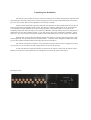
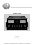
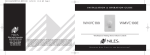
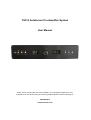
Back Panel View
Connections
Step 1 - Connect Your Source Components
First connect your source components to the TAP-X. The Standard TAP-X can accept up to 6 single
ended (RCA) input connections. If you use less than 6 inputs then plug them into adjacent inputs starting at input
number 1. The upper (red) RCA inputs are for the right channel and the lower (white) RCA inputs are for the
left channel connections. Inputs are staggered to allow easier access to tighten the cable's RCA connectors.
Step 2 - Connect Your Amplifier(s)
Next connect the interconnect cables from the TAP-X to your amplifiers. Be sure your amplifiers are
turned off while hooking cables up.
Connect OUT1 to your main speaker amplifiers. This output is run via the Autoformer modules and is
normally used as a 100% passive connection from your source to amp. Optionally each input can be easily set to
insert an active buffer stage in-line with the signal path. See below in the 'Buffer Button' section for more
information on this.
Connect OUT2 (Sub Output) to the subwoofer. This output is run entirely separate from the Passive
Main output (#1) and is isolated from the main signal path. Its level always 'follows along' with the main
Autoformer Modules. This is designed to completely separate the sub connection so that you do not need to be
at all concerned with a long cable connecting the pre-amp to the subwoofer amp affecting the main output's
100% passive signal path. If you are bi-amping then use this output to feed the bass amp in the system. Note the
sub output is still full range and does not have a crossover function – that would be part of your subwoofer
system.
Step 3 - Connect the TAPE Output
There are a set of TAPE output connectors on the back of the TAP-X pre-amp. These can be used to
feed a Tape Deck or CD Recorder input jack. These output jacks are switched on and off via a button on the
front panel (the TAPE button - as you might expect). When the led above the button is on the TAPE output jacks
are a buffered feed straight from the currently selected input jack - at unity gain just as if you plugged your
source directly into your recorder. A buffer circuit isolates this tape connection so that it can not affect the main
amp's 100% passive signal path
Note:
This is a bit different than a traditional 'tape loop'. We have chosen this method over a tape loop
because the traditional tape loop introduces additional contacts to the main signal path all the time - even when
the tape function is not used. We prefer to keep the main signal path as clean as we can and only add features
'around' that main signal path.
These switched tape outputs can also be used to feed a headphone amp with its own built in volume
control.
Connections - Cont'd
Step 4 - Power Connection.
Once the TAP-X is in position you can connect it's power supply. The power feeding the TAP-X is not
terribly critical - the are no connections from power to the main output's passive signal path. In the case of the
full feature TAP-X the power is used for the sub out level control and buffer circuit. Once the power is inside the
TAP-X it is routed through a custom R-Core Tamura isolation/splitter transformer to derive the split rails for the
buffer circuit power supply. Power draw is low so just plug the supply into the same power conditioner you use
for your source components. If you run your system directly from the wall supply then just plug the TAP-X's
power supply into the same wall outlets or power strip used. Connect the other end of the power cable cable into
the 'PWR' jack on the back of the TAP-X. The display will light up. The following is the system configuration
of a new TAP-X on initial power up:
–
–
–
–
Volume is muted
Source 1 is selected in Normal (no buffer) mode (green led)
Display Mode is set to match the display toggle on the back of the unit (ON = display stays on / OFF =
display goes off after a command is finished).
TAPE Output is off
Setup
Step 5- Display Toggle Selection
On the back of the TAP-X is a display toggle switch. Since the display mode can also be selected via
the front panel and via remote control all this toggle switch does is set the display mode on power up of the
system - so after a power cycle it will power up in your preferred mode. The two selections for the toggle are:
'ON' - When this mode is selected the TAP-X will power up with the display mode set to ON. In this mode the
front panel display will stay on continuously.
'OFF' - When this mode is selected the TAP-X will power up with the display mode set to OFF. In this mode the
front panel display will be on while the TAP-X is executing a command and then turn off after a short timeout
period. Use this mode if you prefer to have a dark listening room while listening.
Step 6 – Home Theater Bypass Button
On the back of the TAP-X (near the display toggle) is a small black push button labeled 'BYPASS'.
This button can be used to program the currently selected input to 'lock' on any volume level. Pressing this
button programs the currently selected input to the current volume and pressing the button again 'unlocks' the
volume setting. The status of each input is shown via that inputs led on the front panel:
For normal (unlocked) mode the led is green (or orange if the main path buffer for that
is active mode).
input is set to
For lock (or bypass) mode the led will turn red.
The HT mode of each input is saved in non volatile memory so even after a power outage this
programming is stored inside the TAP-X.
Most often this is used to program an input connected to a home theater processor so that the input will
jump to level 54 (unity gain) when that input is selected. As a non HT input is once again selected the level
jumps back to the prior level setting. A level 54 setting connects the input jack directly to the output jack. An
alternate level can also be used if you'd like. Each time that source is selected the level will jump to the
programmed level and you use the HT processors level control to set the volume - which also controls the other
channels such as rear channels, etc... If your HT processor already had its levels set for the same amplifiers
directly connected to the HT Processor then using level 54 (unity gain) on the TAP-X will maintain proper
surround channel vs main channel levels. If you are installing the processor new or making other changes in the
system then you should set the TAP-X to an HT mode for that processor input BEFORE you set your surround
levels. That way the system levels will be correct each time that input is selected.
The volume could simply be set manually to the same level each time you use that input. The HT button
is simply a handy way to make the level jump automatically to the same volume each time that input is selected
and more importantly to automatically return to the previous level setting when a non HT input is again selected.
NOTE:
In some systems switching to an unused input will cause a small amount of hum at the speakers. This is
because with no input connected the signal path is 'hanging in the breeze' picking up whatever noise is floating
by. For unused inputs HT mode can be engaged and set to volume level 1. Then when selected the level is so low
that there will be no hum.
Using The TAP-X
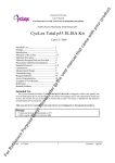
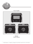
The Front Panel
Display Button / Led:
Each button press toggles between the 2 display modes. When the led is on (display mode on) the
display stays on continuously. When the led is off (display mode off ) the display will be on while you are using
the pre-amp / remote functions and then after a short timeout the display turns off for dark listening. The Red
button on the upper left corner of the remote also toggles the display mode.
TAPE Button / Led:
The TAPE button toggles between TAPE Output On and TAPE Output off. See TAPE output
connection details above for information on how the TAPE Output functions.
Mute Button / Led:
This button toggles between mute and normal volume modes. When the mute led is on the system is
muted. The mute button on the remote also toggles mute mode. Adjusting volume via the remote or the volume
knob resets the TAP-X to not muted.
Left Channel Volume Display:
This numeric led displays the current volume of the left channel.
- In Mute Mode the display reads double dashes “--”
- The lowest volume level (level 1) is -52db attenuation
- Unity Gain ( 0db attenuation) is at level 54
- The highest volume level (level 61) is +7db of gain
Volume Knob:
Not much to say - it's a volume knob.
Right Channel Volume Display:
This numeric led displays the current volume of the right channel.
- In Mute Mode the display reads double dashes “--”
- The lowest volume level (level 1) is -52db attenuation
- Unity Gain ( 0db attenuation) is at level 54
- The highest volume level (level 61) is +7db of gain
Using The TAP-X
The Front Panel - Continued
Just to the right of the Right channel numeric display are the source select functions:
Source Down Button:
Each button press changes the selected source to the next lower source. If this button is pressed while
source 1 is selected the source wraps around to source 6. The current source is indicated via a row of leds just
above the source buttons.
Buffer Button:
Pressing this button toggles the currently selected source between 'Normal' and 'Buffered' mode. The
selected Buffer mode is indicated via the source leds just above the source buttons. Normal mode is indicated by
a green led and buffered mode is shown by the source's led turning orange. There is a button on the remote to
toggle the buffer mode (upper right corner of remote handset).
Note:
Buffer mode places a unity gain buffer in the signal path before the Autoformers. It is only intended to
be used if one of your non critical sources (ie. a VCR or older Tuner) should have trouble driving a passive preamp - the buffer can be selected to allow the source to be used in the system.
Please don't spend time trying to 'predict' if you need the buffer or not. It is VERY simple to experiment
with the buffer mode - just sit listening to music and toggle the buffer mode using the remote handset. The best
sounding mode is the correct mode! It is expected that you won't use buffer mode on your main sources - I have
yet to find a system where I like buffer mode better than 100% passive mode with the primary source. It's really
added as a helper in case any of your additional (lower quality) sources have trouble driving a passive pre-amp.
Buffer mode selection is automatically stored for each input in non volatile memory - so it will be saved
after power is lost. This way each source will remember its preferred mode so once those modes are set you do
not have to adjust the buffer mode buttons again.
As you toggle between Normal and Buffer Mode note there are 2 buffer modes - one has the decimal
point in the left volume display on and the next has the decimal point in the right volume display on. Right now
TAP-X pre-amps have both these modes running through identical buffers. There is a location inside the TAP-X
to allow a buffer daughter board to be added so the TAP-X would have two different buffer modes. This way if
we ever run into a buffer that we really like and one that could be useful even of very good sources it can easily
be added to units in the field without any re-programming needed.
Source Up Button:
Each button press changes the selected source to the next higher source. If this button is pressed while
source 6 is selected the source wraps around to source 1. The current source is indicated via a row of leds just
above the source buttons.
Source LEDs:
Above the source/phase buttons are a row of 6 leds. They indicate the selected source number. The left
most led is source 1 and the right most led is source 6.
Green = Normal (Buffer Mode Off)
Orange = Buffer Mode On
Red = HT bypass (lock to volume 'xx').
Remote Handset Functions
Display On / Off (The Red button on the upper left corner):
Each button press toggles between the 2 display modes. When the display led is on (display mode on)
the display stays on continuously. When the led is off (display mode off ) the display will be on while you are
using the pre-amp / remote functions and then after a short timeout the display turns off for dark listening.
Buffer Mode (The Black button on the upper right corner):
Pressing this button toggles the currently selected source between 'Normal' and 'Buffer' mode. The
current buffer mode is indicated via the source leds just above the source buttons. Normal mode is indicated by a
green led and 'Buffer Mode' is shown by the source's led turning orange. Note that there are 2 'stops' in buffer
mode. Both these are identical for now – the extra stop is included to allow a future buffer to be easily inserted
into your TAP-X.
Mute (center of volume/balance grid):
This button toggle between mute and normal volume modes. When the mute led is on the system is
muted. The mute will be canceled when the volume is adjusted by the remote handset or by the volume knob on
the front of the pre-amp.
Volume UP / Down ('+' and '-'):
The volume up and down buttons step the volume up or down 1 step (1db) per button press or if held
down continuously they continuously adjust volume.
Balance Left / Right ('<' and '>'):
The Balance Left / Right buttons step the volume levels to adjust the balance. This adjustment moves
the sound to the right or left side by 1 volume step per button press (or if held down continuously balance will
progressively move in the desired direction). A sliding / alternating balance is implemented where the level
adjustment to move balance alternates from left or right, etc... This way the overall volume level of the system is
maintained. Also you can slide balance over to one side and then slide it back to the original volume by pressing
the opposite balance button. If you hold the button down constantly while moving back towards center then the
balance will stop as it reaches center. This is handy when adjusting balance back to the middle point.
Source Select Buttons:
The buttons labeled '1' through '6' on the bottom portion of the remote handset directly access each of
the 6 source inputs on the TAP-X. These direct buttons (rather than next/prev) are used to make sure that macro
functions programmed into a (user supplied) advanced programmable handset function repeatably.
TAP-X Features and Specifications
Features:
* Continuous 1db Level Steps from -52 to +7db
* Gain Mode automatically engages as the level is turned above unity gain (step 54)
* Remote Control of Level, Balance, Input Select, Buffer Mode, Mute, and Display
* Front Panel Control of Level, Input Select, Buffer Mode, Mute, TAPE, and Display
* Buffered and Switched TAPE Output (6 input version only)
* 100% passive or Buffer Mode for main output via remote or front panel (6 input model only)
* Any Input(s) can be programmed as an HT Input via a simple back panel button press
* Separate Buffered and level controlled Sub Output (6 input model only)
* Six input version = 6 RCA Inputs + SUB Out + Main Out
* One input version = 1 RCA In + Dual RCA outputs
* Custom Remote Control Handset
* Display Dark setting for HT or dark listening
* Optional Channel Expansion Modules have trim up / trim down buttons for each channel
Performance:
* 'Teflon like' Arlon PCB Material used for Signal Path Circuit Boards
* Extreme quality relays rated for billions of operations
* Modular Design for minimum internal wiring keeping the signal path VERY clean
* Expansion modules connect via fiber optic cables - no chance of ground loops
* Entire Control System enters sleep mode after each command - NO clock noise
Endurance:
* A Minimum of Mechanical Parts - Maintenance free operation
* All switching via sealed relays rated for billions of operations
* Optical Encoder Level Control rated for millions of operations
* Optional Fiber Optic Expansion ports to add unlimited additional channels
Autoformer Pre-amp Specifications:
* Bandwidth: Below 10 Hz to over 100 KHz ( +/- 1db)
* Right Channel to Left Channel Level Matching: Closer than +/-.05dB
* THD: < 0.0008%
* Step Size: 1db (Mute / -52dB to +7db)
* Maximum Input Level: > 10V RMS
* Standard TAP-X has 2 Channels - Right/Left
* Maximum Channels: Unlimited
* Inputs: 6 RCA.
* Outputs: 2 RCA (100% Passive / Buffered and SUB Output)
* TAPE Outputs: 1 RCA (6 input version only)
* HT Bypass Inputs: Any of the 6 inputs programmed as HT via button press
* Size: 17"W x 8"D x 3-1/4"H