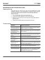
1
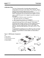
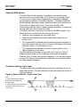
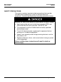
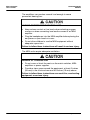
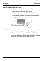
User's Guide Matrix Switcher SLC5608842E and SLC5608842 for Use with C-Bus™ Multi Room Audio Systems Instruction Bulletin Retain for future use. Matrix Switcher User's Guide 63249-420-266A2 06/2010 HAZARD CATEGORIES AND SPECIAL SYMBOLS Read these instructions carefully and look at the equipment to become familiar with the device before trying to install, operate, service, or maintain it. The following special messages may appear throughout this bulletin or on the equipment to warn of potential hazards or to call attention to information that clarifies or simplifies a procedure. The addition of either symbol to a “Danger” or “Warning” safety label indicates that an electrical hazard exists which will result in personal injury if the instructions are not followed. This is the safety alert symbol. It is used to alert you to potential personal injury hazards. Obey all safety messages that follow this symbol to avoid possible injury or death. Danger indicates an immediately hazardous situation which, if not avoided, will result in death or serious injury. Warning indicates a potentially hazardous situation which, if not avoided, can result in death or serious injury. Caution indicates a potentially hazardous situation which, if not avoided, can result in minor or moderate injury. Caution, used without the safety alert symbol, indicates a potentially hazardous situation which, if not avoided, can result in property damage or improper operation. NOTE: Provides additional information to clarify or simplify a procedure. 2 © 2010 Schneider Electric. All Rights Reserved. 63249-420-266A2 06/2010 Matrix Switcher User's Guide PLEASE NOTE Electrical equipment should be installed, operated, serviced, and maintained only by qualified personnel. This document is not intended as an instruction manual for untrained persons. No responsibility is assumed by Schneider Electric for any consequences arising out of the use of this manual. FCC CLASS B This device complies with Part 15 of the FCC Rules. Operation is subject to the following two conditions: (1) this device may not cause harmful interference, and (2) this device must accept any interference received, including interference that may cause undesired operation. This equipment has been tested and found to comply with the limits for a Class B digital device, pursuant to Part 15 of the FCC Rules. These limits are designed to provide reasonable protection against harmful interference in a residential installation. This equipment generates, uses, and can radiate radio frequency energy and, if not installed and used in accordance with the instructions, may cause harmful interference to radio communications. However, there is no guarantee that interference will not occur in a particular installation. If this equipment does cause harmful interference to radio or television reception, which can be determined by turning the equipment off and on, the user is encouraged to try to correct the interference by one or more of the following measures: Reorient or relocate the receiving antenna. Increase the separation between the equipment and receiver. Connect the equipment into an outlet on a circuit different from that to which the receiver is connected. Consult the dealer or an experienced radio/TV technician for help. Changes or modifications to this device that are not expressly approved by Schneider Electric could void the user's authority to operate this equipment. © 2010 Schneider Electric. All Rights Reserved. 3 Matrix Switcher User's Guide 63249-420-266A2 06/2010 PRODUCT LABEL Refer to the warning label appearing on the product illustrated below. Refer to the "Notices" section at the beginning of this bulletin for definitions of the symbols appearing on the label. Carefully read and follow the safety precautions both on the equipment and contained in this bulletin before attempting to install or maintain electrical equipment. IMPORTANT SAFETY INSTRUCTIONS The appliance coupler shall remain readily operable once the product is installed. 1. Read these instructions. 2. Keep these instructions. 3. Heed all warnings. 4. Follow all instructions. 5. Do not use this apparatus near water. 6. Clean only with dry cloth. 7. Do not block any ventilation openings. Install in accordance with the manufacturer’s instructions. 8. Do not install near any heat sources such as radiators, heat registers, stoves, or other apparatus (including amplifiers) that product heat. 9. Do not defeat the purpose of the polarized or grounding-type plug. A polarized plug has two blades with one wider that the other. A grounding type plug has two blades and a third grounding prong. The wide blade or the third prong are provided for your safety. If the provided plug does not fit into your outlet, consult an electrician for replacement of the obsolete outlet. 10. Protect the power cord from being walked on or pinched particularly at plugs, convenience receptacles, and the point where the exit from the apparatus. 11. Only use the attachments/accessories specified by the manufacturer. 12. When a cart is used, use caution when moving the cart/apparatus combination to avoid injury from tip-over. 13. Unplug this apparatus during lightning storms or when unused for long periods of time. 14. Refer all servicing to qualified service personnel. Servicing is required when the apparatus has been damaged in any way such as power supply cord or plug is damaged, liquid has been spilled or objects have fallen into the apparatus, the apparatus has been exposed to rain or moisture, does not operate normally, or has been dropped. 4 © 2010 Schneider Electric. All Rights Reserved. 63249-420-266A2 06/2010 Matrix Switcher User's Guide INTRODUCTION This User's Guide provides information about operating and maintaining the Multi Room Audio (MRA) Matrix Switcher. Refer to the MRA Remote Amplifier User's Guide for more information about operating and maintaining MRA Remote Amplifiers. The MRA system includes a Matrix Switcher, and audio amplifiers. Some of the amplifiers may use external power supplies. In some cases, an MRA Distribution Unit is added to provide an additional audio input. The MRA Matrix Switcher comes in two options: MRA Matrix Switcher: SLC5608842 MRA Deluxe Matrix Switcher: SLC5608842E The Deluxe Matrix Switcher includes an Ethernet port to provide streaming functionality from a local computer. C-Bus Ripple software provides storage of music on a local computer, and then streams the music through the Ethernet to the Deluxe Matrix Switcher. The music tag information, such as artist, album, and song, are transmitted and displayed on an output such as a Touch Screen. The Deluxe Matrix Switcher also has a USB port on the front panel. A USB device is plugged directly into the port, and the music, with the music's tag information is downloaded to the Deluxe Matrix Switcher. Figure 1: MRA System Components KEY: A. Matrix Switcher B. Distribution Unit C. Low Power Remote Amplifier D. Remote Amplifier E. Desktop Amplifier © 2010 Schneider Electric. All Rights Reserved. 5 Matrix Switcher User's Guide 63249-420-266A2 06/2010 About the MRA System The Multi Room Audio System is installed in rooms with audio sources such as an audio/video (A/V) receiver, a CD player and a TV set top box. Digital audio connections on the Matrix Switcher send program material to the MRA amplifiers. The Matrix Switcher distributes the selected program material to each of the amplifiers in the system. At each audio zone, C-Bus wall switches and touchscreens can be used to make program selections, to adjust the volume and tone, and to mute the audio. The Matrix Switcher is the control center for the MRA system. The Matrix Switcher can perform the following functions: Select a music program for any audio zone. Select and distributes any preset radio station selections to audio zones. The Deluxe Matrix Switcher sends streaming audio programs to the audio zones from a variety of sources, including a local area network (LAN), or a USB memory stick. The Deluxe Matrix Switcher connects a music player to the Matrix Switcher's front panel. The Deluxe Matrix Switcher is used with a PC running. C-Bus™ Ripple software controls the streaming audio feature using the Ethernet LAN. Contact your system integrator to set up the program on your PC. Refer to the application Help files for more information on C-Bus Ripple Software. The Matrix Switcher Front Panel The Matrix Switcher provides status and control functions for up to eight audio zones. The main features of the front panel are shown in the figure below. Figure 2: Matrix Switcher - Front Panel View KEY: A. USB connector port (Deluxe Matrix Switcher model only) B. LCD screen C. Zone selection pushbuttons (x8) D. Auxiliary (AUX) port (3.5 mm stereo jack) 6 © 2010 Schneider Electric. All Rights Reserved. 63249-420-266A2 06/2010 Matrix Switcher User's Guide Table 1: Matrix Switcher Front Panel Features Connection/Indicat Description or Function or USB connector port socket 1 – Type A (Deluxe Matrix Switcher model only) Allows MP3 files to be played from a device such as a USB drive using the streaming audio feature on the Deluxe Matrix Switcher. The front USB port operates independently from the USB socket located on the rear panel. LCD screen Shows the program selection choices. Pressing a Zone selection button displays the name and input source of the zone. If one or more internal tuners are configured, the active radio station(s) along with the approximate signal strength will be displayed on this screen. Zone selection pushbuttons The audio program for each connected audio zone is selected through the eight push buttons. Pressing the button again within 8 seconds selects the next input source and routes it to the zone. AUX port (3.5 mm stereo jack) This socket lets you connect an audio source, such as a portable audio player. The AUX socket is electrically connected to Source Input 4 at the back of the unit. If you are using the front panel AUX socket, do not attach cables to Source Input 4 on the rear panel. Refer to the Audio Inputs on the Matrix Switcher - Rear Panel View figure for the location of Source Input 4. © 2010 Schneider Electric. All Rights Reserved. 7 Matrix Switcher User's Guide 63249-420-266A2 06/2010 SAFETY PRECAUTIONS This section contains important safety precautions that must be followed before attempting to install or maintain electrical equipment. Carefully read and follow the safety precautions below. HAZARD OF ELECTRIC SHOCK, EXPLOSION, OR ARC FLASH Apply appropriate personal protective equipment (PPE) and follow safe electrical work practices. See NFPA 70E. This equipment must be installed and serviced by qualified electrical personnel. Turn off all electrical power supplying this equipment before working on or inside the equipment. Always use a properly rated voltage sensing device to confirm that power is off. Replace all devices, doors, and covers before turning on power to this equipment. Failure to follow these instructions will result in death or serious injury. 8 © 2010 Schneider Electric. All Rights Reserved. 63249-420-266A2 06/2010 Matrix Switcher User's Guide There are no user serviceable parts inside the Matrix Switcher enclosure. Replacing the fuse does not require opening the unit cover. Installation should typically be performed by a C-Bus installer. HAZARD OF ELECTRIC SHOCK, BURN, OR ARC FLASH Use only the power supply and cords supplied with the units. Do not substitute power supplies or electrical cords. Plug the unit's power cord into a properly-grounded AC power outlet. Never remove the grounding pin from a power cord plug. This equipment must be installed and serviced by qualified electrical personnel. Do not allow liquids to splash or drip on the equipment. Do not place cables where people are likely to trip over them. Failure to follow these instructions can result in death or serious injury. NOTE: In the event of a spill, unplug the equipment immediately and contact technical support. © 2010 Schneider Electric. All Rights Reserved. 9 Matrix Switcher User's Guide 63249-420-266A2 06/2010 The Matrix Switcher Rear Panel The installer typically completes rear panel connections. Refer to the figure and table below to check cable connections to the rear panel. Many network cables appear similar but have different electrical properties. The equipment can be damaged if cables are plugged into the wrong port. Consult your system installer for proper cable connections. UNSTABLE OPERATION OR NETWORK OVERVOLTAGE Do not connect C-Bus network to a PC communications port. Failure to follow these instructions can cause damage to the equipment. Figure 3: Matrix Switcher - Rear Panel View KEY: A. Power switch B. Infrared outputs C. Digital audio outputs D. Ethernet LAN (Deluxe Matrix Switcher only) E. Audio inputs F. Broadcast inputs G. Unit indicator and C-Bus indicator H. C-Bus RJ45 ports I. Digital audio input J. USB port K. AM/FM antenna L. Optical input/output M. Power cord connection 10 © 2010 Schneider Electric. All Rights Reserved. 63249-420-266A2 06/2010 Matrix Switcher User's Guide Table 2: Rear Panel Features Connection/Indicator Description or Function Power switch Switches the unit on and off. Infrared Outputs (IR OUT 2 – 3.5 mm) These 3.5 mm sockets connect to IR Emitter leads. IR Emitters are then coupled to IR receivers on A/V equipment to provide remote control from any zone. Digital Audio Outputs 8 – RJ45 Each zone output is used to connect the Matrix Switcher to one amplifier in each audio zone. Ethernet LAN 1 – RJ45 (Deluxe Matrix Switcher only) This RJ45 socket enables connection to a local (computer) network for the streaming functionality of the Deluxe Matrix Switcher. Audio Input (Source Inputs) 4 – RCA pairs Most A/V devices connect to the Matrix Switcher through the four standard stereo Analog inputs. These line level RCA sockets are numbered 1 through 4. Input 4 is electrically tied to the front panel AUX connector. This input should be used as either a line-level input (rear panel) or a headphone-level input (AUX input), not both. Broadcast Inputs 2 – RCA Line level mono audio that is connected here is broadcast to all zones that have an analog input source selected. Refer to the Annunciation section of this manual. Unit indicator and C-Bus indicator Unit and C-Bus indicators show network status and activity. C-Bus Ports 2 – RJ45 There are two connections for the C-Bus network to allow for looping through to additional pieces of equipment. Digital Audio Input 1 – RJ45 Use this connection when using an optional MRA Distribution Unit to provide an additional stereo audio input. USB Port 1– Type B This connection is used for programming the Matrix Switcher during commissioning by the installer using a PC running MARPA configuration software. AM/FM antenna 1 – Type-F coaxial One antenna connection serves both internal AM/FM tuners. Optical input/output Used to connect a digital optical audio source for distribution to any of the eight zones. The digital audio format must be 44.1 or 48 kHz stereo. Some digital audio formats (such as surround sound) are not compatible with the Matrix Switcher. The optional output is provided so that the input can be sent on to another piece of A/V equipment. You cannot use the optical input and the DIGITAL AUDIO IN at the same time. Power cord connector and fuse holder Connect the power cord here to power the Matrix Switcher. The Matrix Switcher also provides power for connected amplifiers that do not have an external power supply. The Matrix Switcher requires a 3.15A, 250V, 5x22mm glass fuse. HI/LO adjustment 2 – trimpots These adjust the level of the audio source connected to the mono broadcast inputs. Use a small Phillips screwdriver to rotate the control if the audio source is too quiet or loud. Refer to the Broadcast Audio Input and Adjustment Locations figure for trimpot locations. © 2010 Schneider Electric. All Rights Reserved. 11 Matrix Switcher User's Guide 63249-420-266A2 06/2010 The amplifiers can produce sounds loud enough to cause permanent hearing loss. HAZARD OF PERMANENT HEARING LOSS Keep volume controls at low levels when selecting program sources or when connecting local audio sources to an MRA amplifier. Plug the headphones into the MRA amplifier before placing the ear pieces on your head or in ears. Do not allow children to use the MRA equipment without adequate supervision. Failure to follow these instructions will result in serious injury. The MRA units require adequate ventilation. HAZARD OF OVERHEATING Do not cover or block the vents on the matrix switcher, MRA amplifiers or power supplies. Provide a clear space around the equipment, at least 2 inches (50 mm) to the front and rear and 0.6 inches (15 mm) above. Failure to follow these instructions can result fire, overheating equipment, or serious injury. 12 © 2010 Schneider Electric. All Rights Reserved. 63249-420-266A2 06/2010 Matrix Switcher User's Guide GENERAL USE GUIDELINES General installing, cabling and programming tasks and are described in the C-Bus™ Multi Room Audio Matrix Switcher Installation instruction bulletin, other component instruction bulletins, and in the software Help files. Follow the guidelines below for general use of the Matrix Switcher. Leave the equipment powered ON when not in use. The MRA system uses very little power when not being actively used. The digital audio connections from the Matrix Switcher to the Remote Amplifiers are for MRA system use only. They are not compatible with A/V equipment from other manufacturers. Do not disturb the audio and control cables attached to the rear panel of the Matrix Switcher. The C-Bus, digital audio and Ethernet LAN cables look similar. Never plug them into the wrong sockets. If you are not sure about cable connections, refer to the Installation Instructions or call your system installer. Care and Cleaning Follow these guidelines to properly care for and clean the unit: Clean the unit using a soft lint free cloth. Do not use chemicals or spray cleaners when cleaning. Do not use hard, sharp objects to select the controls. Do not remove any covers or panels. Place cables where people will not trip over them. OPERATION Powering On the Matrix Switcher To power on the Matrix Switcher, press on the lower part of the power switch located on the rear panel toggling the switch to the ON position. When power is applied, the LCD display is active. Figure 4: Power Switch Location KEY: A. Fuse Holder B. Power Cord Connector C. Power Switch © 2010 Schneider Electric. All Rights Reserved. 13 Matrix Switcher User's Guide 63249-420-266A2 06/2010 Selecting a Program for an Audio Zone Listed below are several ways to change a zone’s input source in a typical MRA system installation. A zone selection button on the Matrix Switcher The Source selection buttons on a Desktop Amplifier An infrared (IR) remote control used with a Desktop Amplifier An appropriately configured C-Bus wall switch or touch screen. Figure 5: Selecting a Prrogram Source for a Zone Streaming Audio If your Matrix Switcher supports audio streaming, program material can be sent to the audio zones using an Ethernet LAN connection or a USB thumb drive at the front panel USB port. Use C-Bus Ripple software to manage streaming content. NOTE: The USB socket on the back panel is provided for setup and configuration purposes. It is not used as an audio input. 14 © 2010 Schneider Electric. All Rights Reserved. 63249-420-266A2 06/2010 Matrix Switcher User's Guide Annunciation (Optional) The Matrix Switcher has the capability of announcing the name of an input source whenever it is selected. Annunciation provides instant feedback when changing the source selection using a C-Bus switch, amplifier or remote control. Annunciation is broadcast through the speakers in the zone where the input source has changed. Using MARPA configuration software, the installer can disable this feature. Figure 6: Broadcast Audio Input and Adjustment Locations KEY: A. LO Priority Level Adjustment B. LO Priority Mono Input C. HI Priority Mono Input D. HI Priority Level Adjustment The following actions may vary depending on how the installer configures the Matrix Switcher. Audio connected to the low priority input is broadcast at the currently set volume, to all amplifiers that are switched on and have Source Input 1, 2, 3 or 4 selected. The installer uses MARPA configuration software to set the volume of the audio connected to the high priority input that is broadcast to all amplifiers. Any amplifiers in standby mode are switched on to ensure the audio is broadcast as widely as possible. Five seconds after the broadcast audio ceases, amplifiers return to standby (if applicable) and to the previously set volume. A high priority (HI) broadcast uses left and right channel speakers. A low priority (LO) broadcast uses right channel speakers only. Audio connected to a high priority broadcast input must be of sufficient volume to trigger a broadcast. © 2010 Schneider Electric. All Rights Reserved. 15 Matrix Switcher User's Guide 63249-420-266A2 06/2010 MAINTENANCE AND TROUBLESHOOTING Replacing the Fuse Other than the fuse, there are no other user serviceable parts inside the Matrix Switcher. If fuse replacement is required, always use the correct fuse listed on the rear panel. Follow the steps below to replace the fuse. Turn off the power switch and unplug the unit. Locate fuse holder adjacent to the cord connector. Replace the fuse with the correct type and rating described on the rear panel. Close the fuse holder and restore power to the unit Troubleshooting Symptom Possible Explanation There is no sound after switching the amplifier ON (sound worked previously). The volume may have been set to minimum, or the amplifier may have been muted (on a desktop amplifier) before the amplifier was switched off. The default volume, bass or If a power failure occurs when the amplifier is ON, the volume, bass and treble settings are saved and become treble settings have changed (when switching the new defaults. the amplifier ON). The matrix switcher no longer responds to button presses. Turn the Matrix Switcher off for several seconds, then on. Use the power switch on the rear of the matrix switcher, next to the power cord socket. The Matrix Switcher does not power up. The fuse may need replacing. Remove the power cord from the power outlet before replacing the fuse. A mains circuit breaker trips This may occur if more than five amplifier power supplies when amplifiers are are connected to the same circuit, due to a high inrush powered up. current. An amplifier switches off, particularly when the volume is loud. If insufficient current is available for the amplifier, it will switch itself off. This may occur if the amplifier receives its power from a matrix switcher. The amplifier may need its own external power supply unit. The level of the audio connected to the broadcast input Audio is not broadcast via the matrix switcher’s high may not be sufficient to trigger the broadcast. priority (HI) broadcast input. Cannot hear any sound The digital audio source may be connected to the optical when using the optical input output instead of the input (on a Matrix Switcher). Some digital audio formats (such as surround sound) are incompatible with the MRA system. 16 © 2010 Schneider Electric. All Rights Reserved. 63249-420-266A2 06/2010 Matrix Switcher User's Guide SPECIFICATIONS Table 3: Specifications – Matrix Switcher Parameter Description Supply Voltage 120 Vac Mains frequency range 47 to 53 Hz and 57 to 63 Hz Power consumption 220 VA maximum C-Bus network voltage 15 to 36 Vdc C-Bus sink current 22 mA; the matrix switcher does not supply current to the network C-Bus AC input impedance 80 kΩ @ 1 kHz Network clock and burden Software selectable Source input signal level 2.8 V p-p maximum (47 k Ω) A/D conversion 16 bit PCM Operating temperature 10 to 40 °C (50 to 104 °F) Operating humidity 10 to 90% RH (non-condensing) Table 4: System Audio Output Specifications Parameter Description Frequency response 40 Hz to 20 kHz (+2.4 dB / -0.75 dB) Total harmonic distortion (1 kHz, 20 W RMS into 4 Ω) 0.16% at 1 kHz, 20 W RMS into 4 ohms Signal to noise ratio > 63 db (peak, unweighted) STANDARDS The Matrix Switcher complies with the following Standards: Table 5: U.S. and Canadian Product Safety Standards and U.S. FCC Regulations Standards/Regulations Title CSA C22.2 No. 205 Signal Equipment UL60065 Video and Similar Electronic Apparatus FCC Part 15 Class B Digital Device for Home or Office Use © 2010 Schneider Electric. All Rights Reserved. 17 Matrix Switcher Instruction Bulletin SUPPORT AND SERVICE Contact the Customer Information Center for technical support by phone at 1-888-778-2733 or e-mail at [email protected]. Contact your local Schneider Electric service representative or CBus™ system certified installer for repairs or service to your network. You may also find helpful information on our web site at www.Schneider-Electric.us. Schneider Electric, USA 320 Tech Park Drive, Suite 100 La Vergne, TN, 37086 1-888-778-2733 www.schneider-electric.us C-Bus, Saturn and Neo are trademarks or registered trademarks of Schneider Electric and/or its affiliates in the United States and/or other countries. Electrical equipment should be installed, operated, serviced, and maintained only by qualified personnel. No responsibility is assumed by Schneider Electric for any consequences arising out of the use of this material. © 2010 Schneider Electric. All Rights Reserved. 63249-420-266A2 06/2010