1
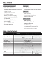
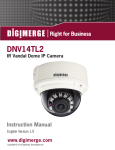
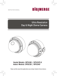
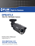
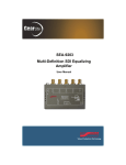
Polaris Vision3 Day & Night Dome Camera www.digimerge.com V2.0 INSTRUCTION MANUAL Polaris Vision3 Day & Night Dome Camera Vandal Model: DPV34D / DPV24TLXR Indoor Model: DPD34D Please read this manual thoroughly before use and keep it handy for future reference. -i- -ii- the -iii- FEATURES All Models Feature: DPD34D • 1/3” Sony Ex-View™ II 960H • Indoor Dome Model • Excellent low light performance using Polaris Vision3 • Camera Mounting: Surface / Semi-Flush Mounting • 0.03Lux/F1.2 (Color) DPV34D • 0.00002Lux w/Sense-Up at x512 • Vandal Dome Model • 700+ TV lines of resolution • Camera Mounting: Surface Mounting • 3D Digital Noise Reduction (3D-DNR) • Weatherproof Rated (IP66) • Advanced Shadow Reduction (D-WDR) • OSD menu control DPV24TLXR • Privacy Masking / Motion Detection • Vandal Dome Model • VIDEO OUT(BNC) • Camera Mounting: Surface Mounting • Operates in 12VDC or 24VAC • Weatherproof Rated (IP66) • Test Monitor Output (RCA) • Smart IR Technology • True Day/Night with ICR mechanism (TDN) • ArcticPro technology with built-in heater SPECIFICATIONS General Power source Power consumption Minimum Power Requirement Image sensor Total pixels Scanning system Scanning frequency Sync. system Resolution Min. illumination Video output S/N Ratio Power input Video output Lens mount Lens Operating temperature Operating humidity DPD34D DPV34D DC 12V / AC 24V +10% 2.5Watt Max 191mA DPV24TLXR 13.2Watt Max 1.1A (Heater On) 1/3” Sony Ex-View™ II 960H 976 (H) x 494 (V) 2:1 interlace 15.734KHz(H), 59.95Hz(V) Internal / Line Lock 700+ TV Lines 0.0 LUX with IR LED On 0.00002 LUX (F1.2) Slow Shutter (x512) 1.0 Vp-p (75 ohm, composite) more than 50dB (AGC OFF) 2-Pin terminal block (Detachable) BNC Connector (2nd video RCA) Fixed mount 2.8 - 12mm F1.4 2.8 - 10.5mm F1.4 Varifocal DC Auto Iris Varifocal DC Auto Iris -10~50°C -40~50°C 0-90% RH -1- 4.4" (112 mm) MEASUREMENTS 3.4" 87 mm Ø 0.1" 3.5 mm 3/4’’ -14 NPS thread 5.1" (130 mm) 3.9" 100.0 mm Vandal Dome Dimensions Base hole positions 100° 112 mm 4.4 in 137° 123° 5.1" 130 mm Underside Base hole positions Indoor Dome Dimensions 27 mm 1.1 in 39 mm 1.5 in 115 mm 4.5 in Indoor Dome Flush Mount Fitting dimensions Flush Mount Cutout and Fitting Clearance -2- 7 mm .28 in PACKING CONTENTS Indoor Dome package contains the following: Camera in housing----------------------------------1 Camera Locking screws (PA3 Type)------------2 Instruction guide (This Document)--------------1 Surface & Flush Mounting Templates----------2 RCA - BNC test cable-------------------------------1 Junction Box Plate-----------------------------------1 Mounting screw pack-------------------------------1 Vandal Dome package contains the following: Camera in housing----------------------------------1 Camera Locking screws (PM4 Type)-----------3 Instruction guide (This Document)--------------1 Surface Mounting Template-----------------------1 RCA - BNC test cable-------------------------------1 Junction Box Plate-----------------------------------1 Mounting screw pack-------------------------------1 Tamper allen key-------------------------------------1 Conduit Key-------------------------------------------1 Locking Screw Conduit Key Allen Key Mounting Screws Pack. 3pc 70mm / 2.8in Screws 3pc 30mm / 1.2in Screws 3pc 40mm 1.6in plugs JUNCTION BOX PLATE Junction box plate allows fitting of either Vandal dome or Indoor dome to standard 2S, 4S and Octagon junction boxes. Junction Box fitting plate accessories: Junction Box Fiting plate --------------------------1 2S / 4S plate screws (KM3.5 Type)-------------4 Octagon fitting screws (KM4 Type)--------------2 Base Fitting Screws PWM3-----------------------3 88.9 mm 3.5 in 46.0 mm 1.8 in Base Fitting Screw. Octagon Screw 2S / 4S Screw Base Fitting Screws 83.3 mm 3.28 in Screw hole overview Camera base fitting illustration -3- Junction box fitting plate attached to camera JUNCTION BOX INSTALLATION TYPES 2S FITTING a. 2S Fitting requires only 2pcs of 2S/4S screws. Screws Note: You have a reduced space in which to hide cables using this type of installation. Recommended for indoor dome only. Cable Entry 4S FITTING a. 4S Fitting requires 2pcs of 2S/4S screws. Note: Suitable for both indoor and vandal domes. Screws Cable Entry TWO GANG FITTING a. Screws of 2S/4S screws. Note: A two gang provides the most robust vandal domes. Cable Entry OCTAGON FITTING a. Screws Octagon screws. Note: Cable Entry -4- are larger compared to those used for the 2S/4S (M4 type). Suitable for both indoor and vandal domes VANDAL DOME FITTINGS Wall Mount - model # MNTV2XW Pendant Mount - model # MNTV2XC Junction Box Mount - model # MNTV2XB Mount for either Vandal or Indoor Dome. Can also mount MNTV2XC or MNTV2XW. Pendant Cap - model # MNTV2XPC Replaces the need for the camera base. Compatible with ceiling conduit installations. Corner Mount bracket - model # MNTV2XR Can fit either MNTV2XW or MNTV2XJ. Pole Mount - model # MNTV2XP Can fit either MNTV2XW or MNTV2XJ. Junction Box Attachment for MNTV2XW & MNTV2XC - model # MNTV2XJ Fits either wall mount and ceiling mount. Symmetrical design - reversible for top or bottom conduit. -5- INSTALLATION. VANDAL DOME ATTENTION - If using DC power, follow the correct polarity as marked on the power cable. 1 1) Loosen the three tamper screws using the provided allen key. Lift the dome cover. Note: If you plan to use conduit fitting, remove conduit cap using the provided conduit key. A B A Installation Option 1: Use holes marked with 'A' when installing camera base first. Use short 30mm screws and anchors. B Installation Option 2: Use holes marked with 'B' when installing complete camera housing. Use long 70mm screws and anchors. B A Mounting Template 2 a Allen Key Go to step 4 on page 7 to complete installation. OR Method 2 - Camera Base Install 2b) Use the included mounting template (Installation Option 1) to mark and pre-drill the required holes. Remove the camera base by unscrewing the 3 base locking screws, and turn camera module approx. 5 degrees counter-clockwise to detach camera base from the camera module. Install the base to the correct holes as indicated on the mount template using the 1.2” screws. Go to step 3a. b 3 Conduit Key Method 1 - Direct Attach Install 2a) Use the included mounting template (Installation Option 2) to mark and pre-drill the required holes. Remove 2 of the 3 base locking screws. Use 2pc of the 2.8” screws to mount the camera directly to the mounting surface. Remove the 3rd base locking screw and install the 3rd 2.8” screw. Method 3 - Junction Box Install 2c) (see page 4 for details). Remove the camera base by unscrewing the 3 base locking screws, and turn the camera module approx. 5 degrees counterclockwise to detach camera base from camera module. Install the base to the junction box using the base attachment screws. Go to step 3a. a b 3a) Reinsert camera module into camera base by aligning the arrow notches on the edge of the camera module and the camera base (label on edge of camera module indicates the location of the arrow notch), and turning camera module clockwise to lock into place. 3b) Use the 3 base locking screws to secure camera base to camera module. Go to step -6- 4 on page 7 to complete installation. INSTALLATION. VANDAL DOME 4 4) Remove camera cover by squeezing the back and front of the cover (as indicated by the arrow indicators) at the same time and lifting it up and away from the lens. Arrow 5 5) Insert the included video test cable into the RCA jack and connect to a test monitor to set up camera. Video test cable Zoom 6 Thumb Screw RCA Jack Focus 6a) Adjust camera viewing angle and secure into place by tightening thumb screw using a flat head screwdriver. Note: Lens adjustment levers are by default in the locked position. Turn counter clockwise to unlock. Tighten levers to secure lens setting. 6b) Adjust lens and OSD as required. 6c) Re-attach the camera cover, using the thumb screw as a guide, until it snaps into place. 7 7a) Re-attach the dome cover. Align arrows according to the diagram below to ensure a weatherproof seal. 1 2 1 Arrow on camera base 2 Arrow on camera module (inside camera) 3 3 Arrow on dome cover. Correct arrow alignment 7b) Use the allen key to tighten the tamper screws. Note: Make sure dome cover cord does not get caught in the rubber seal. -7- INSTALLATION. INDOOR DOME (Surface Mounting) ATTENTION - If using DC power, follow the correct polarity as marked on the power cable. 1 1a) Press down on the tab marked with an arrow to lift up the dome cover slightly b a 1b) While pressing on tab, twist the dome cover counter clockwise just a few degrees to release dome cover from back clips. Lift off the cover. Method 1 - Direct Attach Install 2 2a) Use included mounting template to mark and predrill the required holes. Use included 2.8” screws to mount the camera directly to the mounting surface. Go to step a 3 on page 9 to complete installation. OR Method 2 - Camera Base Install 2b) Use the included mounting template (Installation Option 1) to mark and pre-drill the required holes. Remove the camera base by unscrewing the base locking screws (indicated by padlock markings) and turn camera module approx. 5 degrees counterclockwise to detach camera base from the camera module. Install the base as indicated using the 1.2” screws. Go to step 3a. b 3 Method 3 - Junction Box Install 2c) (see page 4 for details). Remove the camera base by unscrewing the 3 base locking screws, and turn the camera module approx. 5 degrees counterclockwise to detach camera base from camera module. Install the base to the junction box using the base attachment screws. Go to step 3a. a b 3a) Reinsert camera module into camera base by aligning the arrow notches, and turning camera module clockwise to lock into place. 3b) Reinstall the base locking screws. (indicated by padlock markings) Go to step -8- 3 on page 9 to complete installation. INSTALLATION. INDOOR DOME (Semi-Flush Mount) ATTENTION - If using DC power, follow the correct polarity as marked on the power cable. 1 1a) Press down on the tab marked with an arrow to lift up the dome cover slightly b a 2 1b) While pressing on tab, twist the dome cover counterclockwise to release dome cover 1c)Remove the camera base by unscrewing the base locking screws (indicated by a padlock markings) and turn camera module approx. 5 degrees counterclockwise to detach camera base from the camera module. a) Note: Always cut using the inside line of the cutout template b c b) Insert camera into cutout. Make sure that the mounting arms are not extended. c) Turn screwdriver clockwise to unlock all of the 3 mounting arms. d d) Continue turning clockwise to move mounting arms down until they make contact with inner mounting surface. Note: Once mounting arms have made contact with the inner mounting surface, do not apply too much pressure to avoid damaging surface. 3 Thumb Screw Zoom Focus a) Remove camera cover by squeezing the back and front of the cover as indicated by the arrow indicators at the same time and lifting it up and away from the lens. b) Insert the included video test cable into the RCA jack and connect to a test monitor to set up camera. (see page 10). c) Adjust camera viewing angle and secure into place by Adjust lens and OSD as required. Note: Lens adjustment levers are by default in the locked position. Turn counter clockwise to unlock. Tighten levers to secure lens setting. 4 a) Re-attach the camera cover, using the thumb screw as a guide, until it snaps into place. b) Reattach dome cover. -9- CAMERA ADJUSTMENT RCA Service Connector Use supplied RCA - BNC cable If you require BNC output. OSD function joystick. Pressing down on joystick acts as ENTER function. MENU TREE SUMMARY EXPOSURE • AUTO • HIGH LUMINANCE • MODE • BRIGHTNESS • LOW LUMINANCE • MODE • DSS MAX • AGC MAX • MANUAL • MODE • SHUT • AGC PIC ADJUST • MIRROR • DIS • EZOOM • LEVEL • SHARPNESS • HUE • B-GAIN • R-GAIN • ZOOM • PAN • TILT WHITE BAL • ATW • SPEED • DELAY CNT • ATW FRAME • ENVIRONMENT • PUSH • USER1/USER2 • ANTI CR • PUSHLOCK • B-GAIN • R-GAIN WDR • MODE • LEVEL • HLC • CLIP LEVEL • SCALE • BLC DNR • DNR MODE • LEVEL DAY / NIGHT • AUTO • BURST • DELAY CNT • DAY> NIGHT • NIGHT> DAY • BW • COLOR • EXT • SMAR T IR • MODE • LEVEL • GAMA OPT PRIVACY • AREA SEL • MODE • POSITION • COLOR • TRANSP • MOSAIC MOTION DET• MOTION DET • DETECT SENSE • BLOCKDISP • DETECT AREA • MONITOR AREA OTHERS • LANGUAGE • LENS • AUTO • MANUAL • TYPE • MODE • SPEED • SYNC • CAMERA TITLE • WPC • VERSION • CAMERA RESET • INT • LL* *LL (Line Lock) sub-menu is only shown when the camera is connected to AC power. -10- CAMERA ADJUSTMENT OSD MENU control Press down on the function joystick to access the setup menu. Joystick has 4 directional buttons. Press down on the middle of the joystick to select menu options. • Main setup menu is displayed on the monitor screen. SETUP MENU SETUP MENU EXPOSURE PICT ADJUST WHITE BAL WDR DNR DAY/NIGHT PRIVACY MOTION DET OTHERS EXIT AUTO ATW AUTO SAVE ALL Select functions by moving the joystick up and down. Move the joystick left and right to change setting values. Press on joystick to confirm selection. If a menu option features a , a sub menu is available which can be accessed by pressing down on the joystick. Once you have finished updating settings, highlight SAVE ALL and press down on the joystick. Then, highlight EXIT and press down on the joystick. If you do not select SAVE ALL, settings changes will be lost when the camera is rebooted. -11- CAMERA ADJUSTMENT EXPOSURE SETUP MENU EXPOSURE PICT ADJUST WHITE BAL WDR DNR DAY/NIGHT PRIVACY MOTION DET OTHERS EXIT AUTO ATW AUTO SAVE ALL Changes the output exposure settings a choice of AUTO(default) or MANUAL. • AUTO AUTO SETUP HIGH LUMINANCE MODE AE+AUTO IRIS 032 BRIGHTNESS LOW LUMINANCE MODE AGC>DSS 098 AGCMAX DSS MAX X4 RETURN HIGH LUMINANCE MODE: BRIGHTNESS: LOW LUMINANCE MODE: AGCMAX: DSS MAX: AE+AUTO IRIS / ME+AUTO IRIS 000-255 Brightness level of operating mode as set above. Default setting is 128 AGC/ SLOW / AGC-DSS / AGC-DSS-AGC / OFF Settings available only when using DC lens. 000-255 Brightness level of operating mode as set above. Default setting is 098 X1-512 -12- CAMERA ADJUSTMENT MANUAL SETUP MODE SHUT AGC SHUT 1/60 (S) 6 (DB) RETURN • MANUAL MODE: SHUT / SLOW Lets you select combination of exposure modes. SHUT: When MODE is set to SHUT, select shutter speed in x / second 1/60 ,1/100, 1/250,1/500,1/1000,1/2000, 1/4000,1/10000 Default setting is 1/60 SHUT: When MODE is set to DSS The shut speed can be 2,4,8,16,32,64,128,256 Default setting is 2 AGC: Set a fixed gain value for the AGC db 6,12,18,24,30,36,42,44.8 -13- CAMERA ADJUSTMENT PICT ADJUST SETUP MENU EXPOSURE PICT ADJUST WHITE BAL WDR DNR DAY/NIGHT PRIVACY MOTION DET OTHERS EXIT Picture and display control settings AUTO ATW AUTO SAVE ALL PICT ADJUST MIRROR DIS EZOOM LEVEL SHARPNESS HUE R-GAIN B-GAIN OFF OFF 032 009 042 104 176 RETURN • MIRROR: OFF/V-FLIP/H-FLIP/HV-FLIP Horizontally and vertically flip the display output. ON / OFF Enable/Disable Digital Image Stabilization. • DIS: • EZOOM EZOOM SETUP 000 512 256 ZOOM PAN TILT RETURN -14- CAMERA ADJUSTMENT ZOOM: PAN: TILT: 000-255 Default 0 000-1023 Default 512 000-512 Default 256 Note: Zoom must be higher than 0 to use Pan and Tilt settings. • LEVEL: 000-063 Screen brightness. • SHARPNESS: 000-015 Screen sharpness. • HUE: 000-100 Adjust the HUE value • R-GAIN: 000-255 Adjust the RED gain. • B-GAIN: 000-255 Adjust the BLUE gain. WHITE BAL SETUP MENU EXPOSURE PICT ADJUST WHITE BAL WDR DNR DAY/NIGHT PRIVACY MOTION DET OTHERS EXIT AUTO ATW AUTO SAVE ALL White Balance can be set to following: ATW / PUSH / USER1 / USER2 / ANTI CR / PUSH LOCK • ATW (Auto Trace White Balance) ATW SETUP SPEED DELAY CNT ATW FRAME ENVIORMENT x0.5 INDOOR 002 002 RETURN SPEED: DELAY CNT: 000-255 Specifies the AE control for ATW Default setting is 239 000-255 Sets the time based of ATW change. Default setting is 16 -15- CAMERA ADJUSTMENT ATW FRAME: ENVIRONMENT: x0.50 / x1.00 / x1.50 / x2.00 Sets pull in frame for magnification Default setting is X0.50 INDOOR / OUTDOOR Set the pull in frame of ATW Default setting is OUTDOOR • PUSH Use white balance regardless of the subject conditions. • USER1/2 User defined Blue and Red gain adjustment USER2 WB USER1 WB 029 034 B-GAIN R-GAIN B-GAIN R-GAIN 045 038 RETURN RETURN B-GAIN: R-GAIN: 000-255 B Gain adjustment for WB 000-255 R Gain adjustment for WB • ANTI CR • PUSH LOCK Activates color rolling suppression. Press down on joystick to set current scene as the white balance level. Place a 18% gray card in front of the lens and select PUSH LOCK for a natural white level. -16- CAMERA ADJUSTMENT WDR SETUP MENU EXPOSURE PICT ADJUST WHITE BAL WDR DNR DAY/NIGHT PRIVACY MOTION DET OTHERS EXIT Wide Dynamic Range. WDR SETUP MODE LEVEL HLC CLIP LEVEL SCALE BLC AUTO ATW AUTO SAVE ALL OFF OFF OFF 000 010 RETURN • MODE:OFF / D-WDR E: OFF / D-WDR D-WDR: Gamma curve, high & low luminance adjusted Default is Off HLC: OFF / ON / AUTO Highlight compensation. CLIP LEVEL: 000-255 Clipping level. Default setting is 0 SCALE: 000-015 BLC: OFF / ON BLC can be enabled with WDR OFF only DNR SETUP MENU EXPOSURE PICT ADJUST WHITE BAL WDR DNR DAY/NIGHT PRIVACY MOTION DET OTHERS EXIT AUTO ATW AUTO SAVE ALL Digital Noise Reduction. This function reduces the background noise in a low luminance environment. -17- CAMERA ADJUSTMENT DNR DNR MODE LEVEL 3D LOW RETURN • DNR MODE: 2D+3D / 3D / 2D / OFF LEVEL: Noise reduction Filter mode. OFF/LOW/MIDLOW/MID/MIDHIGH/HIGH Adjustment of the filter strength. Default setting is LOW DAY/NIGHT AUTO / BW / EXT /COLOR SETUP MENU EXPOSURE PICT ADJUST WHITE BAL WDR DNR DAY/NIGHT PRIVACY MOTION DET OTHERS EXIT AUTO ATW AUTO SAVE ALL Day/Night mode can be set to the following options: COLOR/AUTO/EXT/BW. Select COLOR for a color image or BW for black and white. EXT allows the use of an external trigger to activate day/night operation. Use AUTO to have the camera automatically adjust for Day/Night mode. DAY/NIGHT BURST DELAY CNT DAY - NIGHT NIGHT - DAY OFF RETURN -18- 003 002 005 CAMERA ADJUSTMENT • AUTO BURST: DELAY CNT: DAY - NIGHT: NIGHT - DAY: ON / OFF Selects whether to output the burst signal when night mode has been identified. 000-255 Night/Day identification transfer time. 000-255 Threshold for Night status from day status. 000-255 Threshold for the Day status from night status. • BW SETUP: Allows additional Smart IR settings to be enabled. B/W SETUP SMART IR SMART IR SETUP ON MODE LEVEL GAMA OPT 015 RETURN RETURN MODE: AUTO ON AUTO / CENTER SMART IR AREA 001 009 001 017 TOP BOTTOM LEFT RIGHT RETURN Center option under mode allows the user to define a rectangular area for the Front Light Compensation. -19- CAMERA ADJUSTMENT PRIVACY OFF / ON SETUP MENU EXPOSURE PICT ADJUST WHITE BAL WDR DNR DAY/NIGHT PRIVACY MOTION DET OTHERS EXIT AUTO ATW AUTO SAVE ALL Hide an area so that it is not displayed on the monitor. PRIVACY AERA SEL MODE POSITION COLOR TRANSP MOSAIC 1 / 15 OFF - RETURN AREA SEL: MODE: Select the privacy area to be adjusted. OFF / ON When ON the settings below can be changed Default OFF for all Areas PRIVACY AREA SEL MODE POSITION COLOR TRANSP MOSAIC 1 / 15 ON WHITE 1.00 - RETURN -20- CAMERA ADJUSTMENT POSITION: When selected area selection screen appears: NEXT: PUSH ENTER Move the joystick to move the corners (you can create any 4-sided shape). The selected side is highlighted by a small box. To select the next corner, press ENTER. To return to privacy menu, press enter repeatedly. COLOR: BLACK, RED, GEEEN, BLUE, YELLOW, CYAN, MAGENTA, WHITE. Sets the colors of the mask frames. TRANSP: 1.00 / 0.75 / 0.50 / 0.00 Sets the privacy area transparency. MOSAIC: ON/OFF Sets the privacy mask as mosaic. MOSAIC is not available if TRANSP is 1.00 MOTION DET SETUP MENU EXPOSURE PICT ADJUST WHITE BAL WDR DNR DAY/NIGHT PRIVACY MOTION DET OTHERS EXIT AUTO ATW AUTO SAVE ALL The motion detection areas of the screen are broken into 24 x 16 rectangular blocks. Use MONITOR AREA to configure always-on motion alert areas on the screen. -21- CAMERA ADJUSTMENT MOTION DET MOTION DET DETECT SENSE BLOCK DISP DETECT AREA MONITOR AREA OFF OFF 111 RETURN MOTION DET: DETECT SENSE: BLOCK DISP: DETECT AREA: OFF / ON. Turn on or off the motion detection. Default is OFF 0-127 Sets the motion detection sensitivity level. ON/OFF: Displays blocks in areas where motion is detected. Select area of the screen to enable / disable motion detection. DETECT AREA Grid areas: Motion detection enabled Transparent: Motion detection disabled EXIT: HOLD ENTER By default the entire area is enabled for detection. Using the movement arrows you move the 2x2 size block positions around the screen. Press the enter button to toggle this area to enable/diable motion detection. Hold down the enter button to return to the motion detection menu. -22- CAMERA ADJUSTMENT MONITOR AREA : Allows you to configure up to 4 motion detection areas. Areas will be highlighted on the screen and flash when motion is detected within them. Areas will not flash if motion is detected in areas that have been disabled using DETECT AREA. MONITOR AREA AERA SEL MODE TOP BOTTOM LEFT RIGHT 1/4 OFF 000 000 000 000 RETURN AREA SEL: 1/4, 2/4, 3/4, 4/4 Select area to adjust. When enabled, the box colors are: 1 Pink, 2 Green, 3 Blue, 4 Yellow When areas overlap, the area with the lowest number takes priority MODE: TOP: BOTTOM: LEFT: RIGHT: OFF / ON. 000-015 000-015 000-023 000-023 Disable / Enable area Position of the top of the area Position of the bottom of the area Position of the left side of the area Position of the right side of the area Note: TOP value cannot be greater than BOTTOM, and LEFT cannot be greater than RIGHT. Numbers automatically update to prevent invalid positions. -23- CAMERA ADJUSTMENT OTHERS SETUP MENU EXPOSURE PICT ADJUST WHITE BAL WDR DNR DAY/NIGHT PRIVACY MOTION DET OTHERS EXIT AUTO ATW AUTO SAVE ALL Miscellaneous camera functions. OTHERS LANGUAGE ENGLISH LENS AUTO SYNC INT CAM TITLE OFF WPC VERSION CAMERA RESET RETURN • LENS MANUAL / AUTO AUTO IRIS TYPE MODE SPEED DC AUTO 064 RETURN MODE: SPEED: AUTO,OPEN,CLOSE Sets the mechanical iris control mode. 000-255 Sets the convergence speed of the mechanical iris. -24- CAMERA ADJUSTMENT • CAM TITLE OFF / ON Select a camera title to be shown on the screen. CAMERA TITLE SETUP CAMERA ABCDEFGHIJKLMNOPQRSTUV WXYZ0123456789-!#$%&’ ()_`.:;<=> @^*./^*X+/ CHR1 CHR2 CLR POS RETURN Use Up/Down/Left/Right to move around. CLR will clear info. POS allows you to change the title position. • SYNC Camera uses internal sync (INT) when camera is connected to DC power. Line Lock (LL) is used when camera is connected to AC power. If you notice color rolling when the camera is connected to AC power, select LL then select PHASE UP or PHASE DOWN and press ENTER to adjust the phase. SYNC PHASE UP PUSH ENTER PHASE DOWN PUSH ENTER RETURN • WPC (Advanced function; not for normal use) WPC PLEASE COVER THE LENSENTER PW RETURN The WPC (White Pixel Compensation) features is used to correct the CCD if dead pixels are visible. You must cover the lens completely so no light can enter the camera sensor for WPC to work. Press the up, down, left, right, middle button to start the highlight of compensation. When prompts -25- CAMERA ADJUSTMENT • VERSION Gives version information regarding current camera software. VERSION INFO MCU VER ROM VER V1.0.0 NORMAL V1.0.0 RETURN • CAMERA RESET This will reset all settings for all menus to manufacturer defaults. EXIT / SAVE ALL SETUP MENU EXPOSURE PICT ADJUST WHITE BAL WDR DNR DAY/NIGHT PRIVACY MOTION DET OTHERS EXIT AUTO ATW AUTO SAVE ALL • EXIT Exit OSD menu. Exit will keep any changes only until camera is powered off. • SAVE ALL Saves the settings to camera Settings are retained after camera power loss. -26- TROUBLESHOOTING Follow the steps below if you are experiencing trouble with your camera. Contact Digimerge Technical Support if the issue persists. • Nothing appears on the screen. ¤¤ Check that the power cable is connected properly and that the voltage is correct. ¤¤ Check that you have properly connected VIDEO cable to the camera VIDEO output jack and to the monitor/DVR. • The image on the screen is unclear. ¤¤ Is the lens or dome cover stained with dirt? Clean lens or dome cover with soft, clean cloth. ¤¤ Re-position the camera if necessary. ¤¤ Adjust the Zoom and Focus screws as needed. • The image on the screen is dark. ¤¤ If you have an intermediate device, set the impedance to 75Ω / Hi-z. ¤¤ Adjust the monitor contrast & brightness controls. • Image quality is poor. ¤¤ Return the camera OSD to factory default settings (OSD Menu>OTHERS>CAMERA RESET). ¤¤ Verify that the camera is receiving sufficient power. • There is interference in the image. ¤¤ The camera or the cables may be close to a source of high voltage, such as a generator. Reposition the camera if necessary. When the resistance value of copper wire is at [20˚C(68˚F)] Copper wire size (AWG) Resistance (Ω/m) Voltage Drop (V/m) #24(0.22mm2) 0.078 0.028 #22(0.33mm2) 0.050 0.018 #20(0.52mm2) 0.030 0.011 #18(0.83mm2) 0.018 0.006 As shown in the table above, voltage decreases as the wire gets longer. Therefore use of an excessively long adapter output line for connection to the camera may affect the performance of the camera. *Standard voltage for camera operation : DC12V ±10% or AC24V ±10% *There may be some deviation in voltage drop depending on the type of wire and the manufacturer. • Be sure to connect power only after all the installation is complete. • Use the UL listed, CLASS 2 power transformer for 12v DC or 24v AC adapter. -27-