1
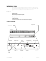
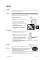
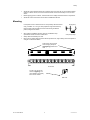
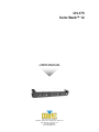
CH-175 Color Bank™ 12 USER MANUAL CHAUVET, 3000 N 29th Ct, Hollywood, FL 33020 U.S.A (800) 762-1084 – (954) 929-1115 FAX (954) 929-5560 www.chauvetlighting.com TABLE OF CONTENT BEFORE YOU BEGIN........................................................................................................................................................... 3 WHAT IS INCLUDED ................................................................................................................................................................................ 3 UNPACKING INSTRUCTIONS .................................................................................................................................................................... 3 AC POWER........................................................................................................................................................................................... 3 SAFETY INSTRUCTIONS .......................................................................................................................................................................... 3 INTRODUCTION ................................................................................................................................................................... 4 FEATURES ............................................................................................................................................................................................ 4 PRODUCT OVERVIEW ............................................................................................................................................................................ 4 SETUP ................................................................................................................................................................................... 5 LAMP ................................................................................................................................................................................................... 5 Lamp Installation ................................................................................................................................................................................................ 5 COLOR GELS ........................................................................................................................................................................................ 5 POWER ................................................................................................................................................................................................ 5 MOUNTING ........................................................................................................................................................................................... 6 OPERATING INSTRUCTIONS.............................................................................................................................................. 7 FOREWORD .......................................................................................................................................................................................... 7 OPERATING MODES............................................................................................................................................................................... 7 Stand Alone .................................................................................................................................................................. 7 Chase Speed...................................................................................................................................................................................................... 7 Audio Activated................................................................................................................................................................................................... 7 Master/Slave ................................................................................................................................................................. 7 Master/Slave settings ......................................................................................................................................................................................... 8 CB-FS Color Bank Footswitch (Optional) ..................................................................................................................... 8 APPENDIX............................................................................................................................................................................. 9 GENERAL MAINTENANCE ....................................................................................................................................................................... 9 RETURNS PROCEDURE .......................................................................................................................................................................... 9 CLAIMS ................................................................................................................................................................................................ 9 GENERAL TROUBLESHOOTING .............................................................................................................................................................. 10 TECHNICAL SPECIFICATIONS ................................................................................................................................................................ 11 CH-175 User Manual 2 2004-09-20/13:36 BEFORE YOU BEGIN What is included ¾ ¾ ¾ ¾ 1 x CH-175 with hanging brackets and knobs Power cord with plug Manual ¾ ¾ 3 color gels of the following colors; yellow, red, blue & green 12 x JCDR 50W 120V lamps Warranty Card Unpacking Instructions Immediately upon receiving a fixture, carefully unpack the carton, check the contents to ensure that all parts are present, and have been received in good condition. Notify the shipper immediately and retain packing material for inspection if any parts appear damaged from shipping or the carton itself shows signs of mishandling. Save the carton and all packing materials. In the event that a fixture must be returned to the factory, it is important that the fixture be returned in the original factory box and packing. AC Power To determine the power requirements for a particular fixture, see the label affixed to the back plate of the fixture or refer to the fixture’s specifications chart. A fixture’s listed current rating is its average current draw under normal conditions. All fixtures must be powered directly off a switched circuit and cannot be run off a rheostat (variable resistor) or dimmer circuit, even if the rheostat or dimmer channel is used solely for a 0% to 100% switch. Before applying power to a fixture, check that the source voltage matches the fixture’s requirement. AC Voltage Switch Check the fixture or device carefully to make sure that if a voltage selection switch exists that it is set to the correct line voltage you will use. Warning! Verify that the power select switch on your unit matches the line voltage applied. All fixtures must be connected to circuits with a suitable Earth Ground. Not all fixtures have a voltage select switch. Please be sure to connect to the proper voltage. Safety Instructions Please read these instructions carefully, which includes important information about the installation, usage and maintenance? • • • • • • • Please keep this User Guide for future consultation. If you sell the unit to another user, be sure that they also receive this instruction booklet. Always make sure that you are connecting to the proper voltage and that the line voltage you are connecting to is not higher than that stated on decal or rear panel of the fixture. This product is intended for indoor use only! To prevent risk of fire or shock, do not expose fixture to rain or moisture. Make sure there are no flammable materials close to the unit while operating. The unit must be installed in a location with adequate ventilation, at least 50cm from adjacent surfaces. Be sure that no ventilation slots are blocked. Always disconnect from power source before servicing or replacing lamp or fuse and be sure to replace with same lamp source. Caution! CH-175 User Manual • • • • • • Secure fixture to fastening device using a safety chain. Never carry the fixture solely by its head. Use its carrying handles. Maximum ambient temperature is Ta: 40°. Do not operate fixture at temperatures higher than this. In the event of serious operating problem, stop using the unit immediately. Never try to repair the unit by yourself. Repairs carried out by unskilled people can lead to damage or malfunction. Please contact the nearest authorized technical assistance center. Always use the same type spare parts. Don’t connect the device to a dimmer pack. Make sure power cord is never crimped or damaged. Never disconnect power cord by pulling or tugging on the cord. Avoid direct eye exposure to lamp while it is on. There are no user serviceable parts inside the unit. Do not open the housing or attempt any repairs yourself. In the unlikely event your unit may require service, please contact CHAUVET. 3 2004-09-20/13:36 INTRODUCTION The Color Bank 12 is a compact striplight also referred to as a borderlight. It is ideal for providing basic area washes for small stages yet small and lightweight enough for mobile applications. Other applications include cove, perimeter, merchandise, and wall wash illumination. Features • • • • • • • • 12 color gel holders 16 built-in programs for stand-alone operation 4 channel chase (3 lamps per channel) Light to sound and chase mode Chase speed control Sound sensitivity knob Full On override button Footswitch controls Chase, Audio, Full On, & Blackout function (Optional) Product Overview Hanging bracket Lamp/Gel-holders Front Panel 1 2 3 4 1 2 4 3 1 2 3 4 Rear Panel Full On override button Channel LED indicator Sound sensitivity rotary knob 5-pin DIN connectors for daisy chain linking Power connector & fuse capsule FOOL SWITCH Full on 220V FULLO N SOUND Mode LED indicator - Full ON - Audio - Chase CH-175 User Manual Mode change button 110V SPEED Chase speed rotary knob 4 Footswitch connector Voltage switch 2004-09-20/13:36 SETUP Lamp You will need to install the lamps prior to the initial operation of the fixture. Twelve JCDR 50W 120V MR-16 halogen lamps are included. Warning! When replacing the lamp, please wait 15 minutes after powering down to allow the unit to cool down! Always disconnect from main power prior to lamp replacement. Do not touch the envelope (glass area) of the bulb with bare hands. If this happens, clean the lamp with alcohol and wipe it with a lint free cloth before installation. LA M P IN STA LLA T ION Remove screws 1) Remove the 2 screws on the lamp/gel-holder face plate. 2) If replacing the lamp, remove old lamp first. 3) Slide the lamp out of the retaining clips. 4) Detach the lamp from the lamp socket and replace with new lamp. 5) Replace lamp lamp/gel-holder face plate, align the screw holes and fasten the screws. 6) No lamp alignment is necessary for this fixture since the lamp is already optimized inside the reflector. Color Gels The Color Bank includes color gels. Install them to create color wash changes during the chase sequence. gel 1) Choose any one of the 4 colors and slide the color gel into the open slot on the top side of the lamp/gel holder. 2) When installing the Color Bank in a horizontal orientation, make sure that the slotted end of the lamp/gel holder is pointing upwards. This prevents the gel from falling out over time. 3) When installing the Color Bank in a vertical orientation and in a tight space, ensure the slotted side is not obstructed and that you maintain the ability to insert a color gel. Power Top Side of lamp/gel holder Slide switch up or down depending on your line voltage. Your product is equipped with switch-selectable AC power setting. Warning! Verify that the power select switch on your unit matches the line voltage applied. All fixtures must be connected to circuits with a suitable Earth Ground. • • CH-175 User Manual To determine the power requirements for a particular fixture, see the label affixed to the back plate of the fixture or refer to the fixture’s specifications chart. A fixture’s listed current rating is its average current draw under normal conditions. 5 2004-09-20/13:36 Setup • • • All fixtures must be powered directly off a switched circuit and cannot be run off a rheostat (variable resistor) or dimmer circuit, even if the rheostat or dimmer channel is used solely for a 0% to 100% switch. Before applying power to a fixture, check that the source voltage matches the fixture’s requirement. All fixtures must be connected to circuits with a suitable Earth Ground. Mounting It is important never to obstruct the fan or vents pathway. Mount the fixture Hanging Clamp using, a suitable “C” or “O” type clamp. Adjust the angle of the fixture by loosening both knobs and tilting the fixture. After finding the desired position, retighten both knobs. • • • When selecting installation location, take into consideration lamp Clamp sold separately! replacement access and routine maintenance. Safety cables should always be used. Never mount in places where the fixture will be exposed to rain, high humidity, extreme temperature changes or restricted ventilation. These holes can be used to mount hanging clamps for downlighting positions off a truss Top View Front View The CH-175 can also be used for uplighting. The yoke hardware can equally serve as floor stands. Side View CH-175 User Manual 6 2004-09-20/13:36 OPERATING INSTRUCTIONS Foreword The user buttons on this fixture will become “HOT” to the touch after a few minutes of operation. It is important to set all manual settings within the first few minutes of operation while the unit is cool to warm. Operating Modes The CH-175 can be operated in three ways. • • • A stand-alone mode will listen to sound and run through 16 built in programs. Master/Slave mode will allow linking of up to as many units you want in a synchronized light show to the sound. Can be operated remotely using the CB-FS Footswitch. Stand Alone C H A S E SPE E D Action Notes 1. Press the MODE button until the Chase, blue LED turns on. When you first power up the fixture the default setting will be the Chase mode. 2. Adjust the Chase Speed Rotary Knob for desired chase speed. Chase programs will alternate automatically. AUD IO ACTIVA T ED Notes Action 1. Press the MODE button until the Audio, green LED turns on. 2. Adjust the Sound Sensitivity Knob for optimum performance. Master/Slave The Master/Slave mode will allow you to link up to as many units you want in a daisy chain fashion. In this mode, the first unit in the daisy chain will automatically command all other units following. Connecting the CH-175 for (Master/Slave) operation does not require any menu or setting selections. Simply connect each unit in a daisy like fashion using a CH-DIN20 5 pin DIN cable. Only the first unit in the chain can be controlled by the optional CB-FS footswitch controller. Continued on the following page CH-175 User Manual 7 2004-09-20/13:36 MASTER /SLAVE SETTIN GS 1) Connect the 5 pin plug cable to the LINK (Out) connector of the first fixture. 2) Connect the other end of the 5 pin cable coming from the first fixture to the LINK (In) connector on the next fixture as illustrated below. Daisy Chain Connection Optional Footswitch Controller Note! The CH-175 and CH-158 can also be linked together. CB-FS Color Bank Footswitch (Optional) CB-FS PEDALS PEDAL FUNCTION CB-FS FOOTSWITCH AUDIO/CHASE AUDIO: Activates Audio mode CHASE: Activates Chase Speed mode FULL ON All lights will be turned on. BLACKOUT All lights will be turned off. Only the first unit in the chain can be controlled by the CB-FS footswitch controller. The CH-158 & CH-175 are compatible in this series and can both be linked together. The first unit you choose will control the rest using the CB-FS footswitch controller or in stand-alone mode. CH-175 User Manual 8 2004-09-20/13:36 APPENDIX General Maintenance To maintain optimum performance and minimize wear fixtures should be cleaned frequently. Usage and environment are contributing factors in determining frequency. As a general rule, fixtures should be cleaned at least twice a month. Dust build up reduces light output performance and can cause overheating. This can lead to reduced lamp life and increased mechanical wear. Be sure to power off fixture before conducting maintenance. Unplug fixture from power. Use a vacuum or air compressor and a soft brush to remove dust collected on external vents and internal components. Clean all glass when the fixture is cold with a mild solution of glass cleaner or Isopropyl Alcohol and a soft lint free cotton cloth or lens tissue. Apply solution to the cloth or tissue and drag dirt and grime to the outside of the lens. Gently polish optical surfaces until they are free of haze and lint. Do not to touch the lamp glass when cleaning fixture. Oil and dirt can cause damage and premature aging of the lamp. In the event that the lamp is touched or becomes dirty, clean the lamps with an alcohol wipe. The cleaning of internal and external optical lenses and/or mirrors must be carried out periodically to optimize light output. Cleaning frequency depends on the environment in which the fixture operates: damp, smoky or particularly dirty surrounding can cause greater accumulation of dirt on the unit’s optics. Clean with soft cloth using normal glass cleaning fluid. - Always dry the parts carefully. - Clean the external optics at least every 20 days. Clean the internal optics at least every 30/60 days. Returns Procedure Returned merchandise must be sent prepaid and in the original packing, call tags will not be issued. Package must be clearly labeled with a Return Merchandise Authorization Number (RA #). Products returned without an RA # will be refused. Call CHAUVET and request RA # prior to shipping the fixture. Be prepared to provide the model number, serial number and a brief description of the cause for the return. Be sure to properly pack fixture, any shipping damage resulting from inadequate packaging is the customer’s responsibility. CHAUVET reserves the right to use its own discretion to repair or replace product(s). As a suggestion, proper UPS packing or double-boxing is always a safe method to use. Claims Damage incurred in shipping is the responsibility of the shipper; therefore the damage must be reported to the carrier upon receipt of merchandise. It is the customer's responsibility to notify and submit claims with the shipper in the event that a fixture is damaged due to shipping. Any other claim for items such as missing component/part, damage not related to shipping, and concealed damage, must be made within seven (7) days of receiving merchandise. CH-175 User Manual 9 2004-09-20/13:36 Appendix General Troubleshooting Applies to Symptom Solution(s) Auto shut off Check fan thermal switch reset Beam is very dim or not bright Clean optical system or replace lamp Breaker/Fuse keeps blowing Check total load placed on device Chase is too slow Check users manual for speed adjustment Device has no power Check for power on Mains. Lights Foggers & Snow Controllers Dimmers & Chaser 9 9 Check 220/110v switch for proper setting 9 9 9 9 9 9 9 Check device’s fuse. (internal and/or external) Lamps cuts off sporadically Possible bad lamp or fixture is overheating. Motor movements are jerky or jumpy Possible bad motor driver or sensors Moves slow Check 220/110v switch for proper setting 9 No flash Re-install bulb, may have shifted in shipping 9 No light output Check slip ring & brushes for contact 9 Lamp may be at end of its life. 9 9 Check polarity switch on controller 9 Install bulb Call service technician Relay will not work Check reset switch 9 Check cable connections Remote does not work Make sure connector is firmly connected to device 9 Unit wobbles when rotating Check for damages possibly incurred during shipping 9 CH-175 User Manual 10 9 2004-09-20/13:36 Appendix Technical Specifications WEIGHT & DIMENSIONS Length........................................................................................................................... 140 mm (5.51 in) Width ........................................................................................................................ 1100 mm (43.31 in) Height ........................................................................................................................... 175 mm (6.89 in) Weight ........................................................................................................................... 6.1 Kg (13.5 lbs) POWER Switch-selectable power setting ....................................................................115V 60 Hz or 230V 50 Hz AC input..............................................................................................................3-prong IEC 60320 C14 LAMPS JCDR-50W-120V x (12) .................................................................................... 1500 hr, 50W 110-130V JCDR-50W-230V x (12) .................................................................................... 1500 hr, 50W 220-240V THERMAL Maximum ambient temperature..........................................................................................65°C (149° F) FUSE Main (115V) ..........................................................................................20mm Glass 7A 125V Fast Blow Main (230V) ..........................................................................................20mm Glass 5A 250V Fast Blow ORDERING INFORMATION Color Bank 12.............................................................................................................................. CH-175 Fuse 7A ............................................................................................................................P170FUSE007 Fuse 5A ............................................................................................................................P170FUSE005 OPTIONS Color Bank Footswitch................................................................................................................... CB-FS CH-175 User Manual 11 2004-09-20/13:36