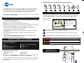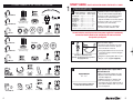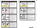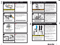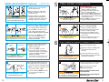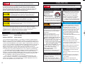
1
TranScape View
TranScape Wave
HC3/GN3
H990
H770
™
™
Instant Hot Water Dispenser
Owner’s Manual
Installation, Care & Use
Instalacion, cuidado & uso
Installation, soin et utilisation
1.800.558.5700
www.insinkerator.com
44068 REV. A
The Emerson logo is a trademark and
service mark of Emerson Electric Co.
Printed in USA
© 2007 InSinkErator, a division of
Emerson Electric Co. All Rights Reserved.
™
™
Identify the model of your instant hot water dispenser and record it here:________________
®
We are delighted that you have chosen the InSinkErator® Instant Hot Water Dispenser
to be a part of your home. This unique appliance will save you time and effort in the
kitchen, and you’ll enjoy discovering new uses for it each day. That’s exactly why
millions of people are now using an InSinkErator Instant Hot Water Dispenser.
We are confident that by following our step-by-step instructions, you’ll soon be enjoying
the convenience of instant hot water.
WHAT YOU SHOULD KNOW BEFORE YOU BEGIN
■ For your satisfaction and safety, read all instructions, cautions, warnings and dangers before installing
or using this instant hot water dispenser.
■ This particular unit is not intended for commercial use.
■ Make sure that all electrical wiring and connections conform to local codes.
■ A standard 120-volt grounded electrical outlet is required under the sink for the dispenser’s electrical power.
■ The wall outlet powering your dispenser must have power supplied to it continuously.
■ This outlet must be fused and should not be controlled by the same wall switch that operates the
disposer, unless you have a SinkTop Switch™ from InSinkErator®.
■ It is recommended that a dedicated control valve be installed on the cold water line supplying water
to this system.
■ If you suspect elevated levels of chlorine in your water, it is recommended to use our water
filtration system.
■ The use of a water filter should NOT result in the water pressure to drop below 30 psi (207kPa).
If it does, this will prevent your unit from operating properly.
■ Moving parts inside the tank causing a rattling noise is normal.
WHAT YOU NEED TO GET STARTED
Equipment Required:
■ Drill
■ T-fitting
■ Dedicated control valve
■ Adjustable wrench
HC3-SS
GN3-SS
H990-SS
H770-SS
HOW TO USE THIS INSTRUCTION MANUAL
These instructions are separated into main sections, indicated by numbers, and subsections,
indicated by capital letters. The manual is setup this way to allow you to take a break at any
point after completing a section or subsection without affecting the installation process.
What you’ll see in the
instruction manual:
INSTALLING THE FAUCET - View/Wave/HC3/GN3
A
View / Wave / HC3 / GN3
Unpack dispenser components.
On a firm, flat surface, carefully
straighten the copper tubing.
2
3
Remove the wing nut from
the valve body.
1
Property Damage: Do not pinch or break copper
tubing. Do not distort the last 1 inch of tubing.
1
Provides a step-by-step narrative describing the installation step, with check boxes that
can be marked as you progress through the installation.
2
Contains simple illustrations that provide visual instruction to support the narrative.
3
CAUTIONS, WARNINGS and DANGERS that will require your attention during the step.
An imminently hazardous situation, which, if not avoided, will result in death or serious injury.
A potentially hazardous situation, which, if not avoided, could result in death or serious injury.
A potentially hazardous situation, which, if not avoided, may result in minor or moderate injury.
■ Phillips and flat blade screwdrivers
■ Pencil
■ Tape measure
■ Level
Equipment You May Need:
■ Anchors for drywall
■ Hole saw
HC-View-SS H-View-SS HC-Wave-SS H-Wave-SS
■ Basin wrench
■ Hole punch
OVERVIEW OF A
COMPLETED SETUP
If you intend to use the sprayer hole in your sink for your dispenser, you may need a basin wrench and a
1/8" plug or a 1/4" cap (not supplied) for the faucet spray hose line. See Step 1-B.
If you need to cut a mounting hole in your stainless steel sink, you may need a 11⁄4" - 11⁄2" hole saw made
for cutting stainless steel or a hole punch. Consult a professional if you are drilling into a surface other
than stainless steel.
2
3
START HERE
COMPONENTS IN THIS PACKAGE
1A
3/8" Tube
3/4" Screws (2)
Brass Nut / Ferrule /
Tube Insert
HC-Wave-SS
Extension & Star Nut
(View & Wave only)
Quick Connector
Wing Nut
Washers
HC3-SS
1-5/8"
1-5/8"
Rubber
Small Steel
H-View-SS
H-Wave-SS
GN3-SS
2-1/4"
2-1/4"
Large Steel
Fiber
Snap-Connect
Fitting (3 pieces)
Tank
Extension & Star Nut
(View & Wave only)
1-5/8"
1-5/8"
Rubber
Small Steel
3/4" Screws (2)
Wing Nut
2-1/4"
2-1/4"
Semi-Circular
Mounting Plate
Wing Nut
Rubber Gasket
4
Fiber Gasket
Metal
Mounting Plate
Mounting Screw
Maximum counter
thickness (depth)
HC-View-SS ...... 25⁄8" ..........................3"
H-View-SS ........ 25⁄8" ..........................3"
HC-Wave-SS .... 25⁄8" ..........................3"
H-Wave-SS ...... 23⁄8"..........................3"
HC3-SS ............ 21⁄4" ..........................3⁄4" *
GN3-SS ............ 21⁄2" ..........................3⁄4" *
H990-SS .......... 11⁄4" ..........................3"
H770-SS .......... 2" ............................1"
* HC3/GN3, a 2" extension is available for oversized counters
Large Steel
Fiber
Snap-Connect
Fitting (3 pieces)
Snap-Connect
Fitting (3 pieces)
faucet, tank and filter (if applicable).
■ Check to make sure there is proper
clearance (see chart at left) for
dispenser handles to be fully opened.
■ Check to make sure counter is not
too thick (see chart at left).
■ Make sure there is a grounded
electrical outlet under the sink.
The wall outlet for your dispenser must have power supplied to it continuously
and must be fused. It should not be controlled by the same wall switch
that operates your disposer.
■ Turn off water supply.
■ Using adjustable wrench, remove nut
connecting sprayer washer flange in
sprayer hole.
If you have to drill through sink or
countertop, you may need to rent or purchase
the appropriate tools.
■ Plug hose opening with either a 1/8"
plug or a 1/4" cap (not supplied).
C
What if you don’t have a sprayer hole or
don’t want to use it?
Tank
Required Hole Size
Tank
1 ⁄4" - 1 ⁄2"
1
1
Consult a professional before drilling into
a surface other than stainless steel.
Snap-Connect
Fitting (3 pieces)
■ Identify locations for the dispenser
■ If using the sink sprayer hose hole,
remove nut that connects sprayer
hose at bottom of faucet.
3/4" Screws (2)
H770-SS
Required minimum from
center of hole to wall
B
Washers
3/4" Screws (2)
H990-SS
PREPARATION
Plug (1)
HC-View-SS
PROPER INSTALLATION SHOULD TAKE ABOUT 2-4 HOURS
■ Many homeowners replace the soap
dispenser in their sink with an instant
hot water dispenser.
■ If drilling a hole into a stainless steel
sink or counter top, you can cut a
mounting hole for the dispenser with a
hole saw for stainless steel, or you can
use a hole punch.
Tank
5
2A
INSTALLING THE FAUCET - VIEW/ WAVE / HC3/ GN3
View/Wave/HC3/GN3
■ Unpack dispenser components.
2A
INSTALLING THE FAUCET - H990
H990
■ Unpack dispenser components.
■ On a firm, flat surface, carefully
■ On a firm, flat surface, carefully
straighten the copper tubing.
straighten the copper tubing.
■ Remove the wing nut from
the valve body.
Property Damage: Do not pinch or break copper
tubing. Do not distort the last 1 inch of tubing.
Property Damage: Do not pinch or break copper
tubing. Do not distort the last 1 inch of tubing.
B
15⁄8" Small
Steel Washer
15⁄8" Small
Steel Washer
15⁄8" Rubber
Washer
11⁄4" Hole
15⁄8" Rubber
Washer
21⁄4" Large
Steel Washer
Cast Iron or
Hole larger than 11⁄4"
BOTH 15⁄8" small steel and rubber washers
MUST BE INSTALLED to ensure
proper operation and seal.
C
than 11⁄4", stack the washers in this
order on sink deck:
1) 21⁄4" large steel washer
2) 15⁄8" rubber washer
3) 15⁄8" small steel washer
Fig. 1
Wing Nut
Fiber
Washer
in the sink or counter until the base
is at rest. Set faucet at desired angle.
Hot & Cool models only
■ Remove plug from the Y-shaped
quick-connector by depressing
release ring. Attach the quick
connector to the ends of the copper
tubes running from the dispenser.
■ Feed tubes down the hole in the
Make sure to use rubber gasket
to ensure proper seal.
C
sink or countertop until the base is
at rest on the sink or countertop
surface.
H990
■ From under the sink, place the
semi-circular mounting plate onto the
threaded stud.
■ Place wing nut onto the threaded
An assistant may be needed to hold
the dispenser head in place
while securing the dispenser.
stud. Make sure faucet head is at the
desired angle. Tighten the wing nut
until snug, while ensuring the semicircular mounting plate extends
beyond the sink hole.
■ Install a white 3/8" tube into
quick connector.
D
Fiber
Washer
H990
■ Ensure that the black rubber gasket
is properly seated into the base of
the dispenser head and will
surround the sink mount.
■ For a cast iron sink, or a hole larger
View/Wave/HC3/GN3
An assistant may be needed to hold
the dispenser head in place
while securing the dispenser.
B
washers in this order on sink deck:
1) 15⁄8" rubber washer
2) 15⁄8" small steel washer.
■ Feed tubes down through the hole
Hot & Cool models only
Star Nut
Fig. 2
Property Damage: Do not over tighten
the plastic wing nut.
6
View/Wave/HC3/GN3
■ For a 11⁄4" sink hole, stack the
View/Wave/HC3/GN3
For counters less than 3/4" thick (Fig. 1)
■ Slide 21⁄4" fiber washer over faucet
threads under sink. Tighten assembly
using black plastic wing nut.
For counters more than 3/4" thick (Fig. 2)
■ Thread extension (only included with
View/Wave) onto base of faucet
until tight. Slide 21⁄4" fiber washer
over extension under sink. Tighten
assembly using plastic star nut.
7
2A
INSTALLING THE FAUCET - H770
H770
3A
MOUNTING THE TANK
■ Select a spot under the sink to mount
■ Unpack dispenser components.
Tank must be
mounted level
to ensure
proper operation.
■ On a firm, flat surface, carefully
straighten the copper tubing.
tank vertically within reach of both
plumbing and electrical connections.
The tank should be within 16" or less
of faucet water lines and within 30"
or less of a standard grounded outlet.
■ While holding tank in place on
Property Damage: Tank must be located within 16" of
faucet and within 30" or less of a standard grounded
outlet. DO NOT extend plumbing or electrical lines.
Property Damage: Do not pinch or break copper
tubing. Do not distort the last 1 inch of tubing.
B
H770
■ Ensure that the fiber gasket is
properly seated against the base of
the dispenser head.
B
the spot selected for installation,
use a pencil to mark locations for
2 hanging screws.
Screws provided are for use in wood
studs or cabinets only. Use wall anchors
(not supplied) for installation into drywall.
■ Pre-drill 1/8" pilot holes at marks.
■ Turn screws into pre-drilled holes,
Leave 1/4" for
hanging tank.
Fiber
Gasket
leaving 1/4" exposed.
Make sure to use fiber gasket
to ensure proper seal.
C
Mount tank vertically in an area that
allows clearance on the underside of the
tank for drainage, if necessary.
DO NOT over tighten screws.
DO NOT remove mounting screw or
fiber gasket from base of dispenser.
H770
■ Feed tubes down the hole in the sink
or countertop until the base is at rest
on the sink or countertop surface.
4A
■ Hang the tank on the screws.
■ Tighten the screws with only 1/2 turn
clockwise.
CONNECTING FAUCET TO TANK
■ Without depressing the gray button,
(1)
(2)
(3)
■ Position faucet head at the
desired angle.
place the snap-connect fitting at
the end of the blue 1/4" tube onto
the left fitting on the tank, pushing
until it clicks into place. (1)
■ Slip the flexible white 7/16" tube
An assistant may be needed to hold
the dispenser head in place
while securing the dispenser.
over barbed middle fitting and slide
down approximately 1/2". (2)
■ Slip the clear 5/16" tube over the far
D
right smooth fitting and slide down
approximately 1/2". (3)
H770
■ From below the sink, place semicircular metal mounting plate over
the mounting screw, ensuring the
mounting plate covers the sink hole.
■ Slide washer over so that the screw
Half moon shaped metal mounting plate
should cradle all descending tubes.
8
is now inside the smaller hole.
Tighten the screw until snug.
Property Damage: Pinched or blocked water lines
may cause damage to the dispenser tank.
Property Damage: Check to make sure
tubes are connected properly and are
pushed down as far as possible.
■ Visually check for pinched or
crimped tubes.
Hose clamps are not needed for any
of the connections.
9
INSTALLING FILTRATION (Optional)
A
Available as an option;
separate purchase required.
■ Mark hole locations for filter head
and bracket in a spot that allows
for filter replacement.
5A
FINAL WATER CONNECTION
Brass Nut
Ferrule
Brass Insert
■ Drill 1/8" starter holes and attach
bracket to wall with wood screws,
turning until snug.
Plastic
tube
■ Remove red filter cap, insert filter
Personal Injury: Do not locate filter above an outlet or other
electrical device. Install head and bracket so that connections
require no stretching, kinking or pinching of tubing.
B
cartridge into filter head and twist
clockwise until “LOCK” arrow on the
filter aligns with arrow on bracket.
■ Determine length of tubing required,
Property Damage: Join remaining tube
to cold water supply only.
A
Brass Nut
then cut to length making sure the
cut is perpendicular and burr-free.
■ Insert a white 3/8" tube into inlet
from water
supply line
to dispenser
side of filter head until it stops.
Press in again to ensure a secure fit.
Ferrule
Copper
tube
■ Insert the other white 3/8" tube
Property Damage: Tube runs need to form to the cabinet’s
contours to allow storage space with no sharp bends. Tubes
need clean, perpendicular, burr-free cuts to ensure a true fit.
C
HC-View
HC-Wave
HC3
H-View/H-Wave
GN3/H990/H770
into outlet side of filter head
until it stops. Press in again to
ensure a secure fit.
■ Insert the copper tube(s) from the
dispenser into the 3/8" to 1/4"
quick-connect fitting.
Property Damage: Join remaining tube
to cold water supply only.
6A
From filter
From filter
Property Damage: Do not extend the copper
lines farther than the 16" provided.
D
■ To redirect filter replacement water
discharge, place 6" clear tube over
vent hole on the left side of filter head.
Discharge
tube
and hold it until water flows from
the spout.
■ Run the water for at least 2 minutes to
Scalding Hazard: The faucet dispenses near-boiling
(212ºF) water which can instantly cause scalds or
burns. Use care when operating this appliance.
B
To dispenser
It is normal for approximately 2 oz. of water to
discharge when filter is removed.
10
■ Check all connections to ensure they are
tight and that there are no leaks.
Water will be cold at first.
connection to water supply.
Allow 12-15 minutes for water to reach
target temperature.
■ Connect remaining white 3/8" tube
to incoming water supply line.
(See Step 5.)
flush lines (both the hot and cold handles
independently if applicable).
■ Plug in instant hot water tank.
■ Note: 3/8" fitting is required to make
From water
supply line
■ Turn on the cold water supply.
■ Depress the dispenser’s HOT handle
from the right outlet on the filter
head into the quick-connect fitting
until it stops. Press in again to
ensure a secure fit.
To remove tube(s) or plug from quick-connector,
depress the release ring and gently pull away.
H-View / H-Wave / GN3/ H990 / H770
■ Install a T-fitting (not included)
onto the cold water supply line.
■ Install dedicated water control valve
with 1/4" compression fitting.
■ At the end of the copper 1/4" tube,
slide the fitting’s brass nut and ferrule
over the tube.
■ Insert the copper tube into the 1/4"
compression fitting and tighten.
FILL TANK & THEN CONNECT POWER
■ Connect the white 3/8" tube
Plug
HC-View / HC-Wave / HC3
■ Install a T-fitting (not included)
onto the cold water supply line.
■ Install dedicated water control valve
with 3/8" compression fitting.
■ At the end of the white 3/8" tube from the
quick-connector, slide the supplied brass
nut and ferrule over the tube and then push
in the brass tube insert.
■ Insert the white 3/8" tube into the 3/8"
compression fitting and tighten.
Property Damage: A standard grounded outlet within
30" of the dispenser is required under the sink. Do
not use an extension cord set with the dispenser.
Gurgling or hissing is normal during the
initial heating cycle.
11
CARE AND USE
Electric Shock Hazard: Using an ungrounded or improperly connected
appliance can result in serious injury or death from electrical shock.
This appliance must be grounded. This instant hot water dispenser is equipped with a cord that
has a grounding conductor and a grounding pin. The plug must be connected to an appropriate
outlet that is properly installed and grounded in accordance with all local codes and ordinances.
Do not modify the plug provided with the appliance – if it will not fit the outlet, have a proper outlet
installed by a qualified electrician. Check with a qualified electrician or serviceman if you are in
doubt as to whether the instant hot water dispenser is properly grounded.
Personal Injury: This tank is a non-pressurized tank. DO NOT modify this system.
DO NOT close vent tube or connect other type dispensers or valves to the tank. Use only
the InSinkErator dispenser faucet supplied. Use only parts provided. Contact an
authorized InSinkErator Service agent for repairs or replacement components.
Fire Hazard: To minimize possibility of fire, DO NOT store flammable items such as
rags, paper or aerosol cans near the tank. DO NOT store or use gasoline or other
flammable vapors and liquids in the vicinity of this or any other appliance.
Property Damage: To avoid water damage, replace any loose or split tubing.
Periodically inspect the unit for any signs of leakage and immediately remove from
service any unit suspected of leaking.
An instant hot water dispenser, like any water heater, has a limited life and will eventually
fail. To avoid possible property damage, this instant hot water dispenser should be
regularly examined for leakage and replaced when necessary. A drain pan, plumbed to
an appropriate drain or outfitted with a leak detector, should be used in those
applications where any leakage could cause property damage.
WARRANTY INFORMATION
Dispenser:
3-year warranty
Stainless Steel Tank:
3-year warranty
Covers all replacement parts and labor to correct defects in material or workmanship in the
dispenser system, excluding the replaceable filter cartridge, for the full warranty period from
the date of installation in your home. If warranty service is required during the warranty period,
contact an authorized InSinkErator service agent to replace or repair the unit in your home at
no cost to you. If your dispenser is replaced rather than repaired, the warranty on the new unit
shall be for the duration of the remaining portion of the original dispenser’s warranty. Note:
Warranty is determined by unit serial number and/or date of installation. Purchase or
installation receipt may be required to verify warranty status. When service is required, and for
the location of your nearest factory authorized service center, call toll free 1-800-558-5700.
The foregoing warranty does not apply to damage or inoperation resulting from accident,
alteration, misuse, abuse, improper installation, installation not in accordance with these
instructions or local electrical and/or plumbing codes. We do not assume any responsibility for
consequential damage. Install using genuine InSinkErator® manufactured components only.
Use of non InSinkErator components will void your warranty.
Some states do not allow limitations on how long an implied warranty lasts, or the
exclusion or limitations of incidental or consequential damages, so the above limitations or
exclusion may not apply to you. This warranty gives you specific legal rights, and you may
also have other rights which vary from state to state.
12
Electric Shock Hazard: To prevent electrical shock, disconnect power before
servicing unit. Use only a properly grounded and polarized electric outlet.
ADJUSTING THE THERMOSTAT
Factory temperature pre-set is 200˚F.
To reset the thermostat to 200°,
turn the indicator two notches to
the right of vertical.
approx. 200°
■ Adjust the thermostat slowly,
turning the dial clockwise
to increase temperature or
counter clockwise to decrease temperature, then
activate faucet handle for 20 seconds to bring in
fresh water to be heated at the new setting. Allow
5-7 minutes for water to reach new temperature.
Scalding Hazard: Do not allow
water to boil. May result in
severe burns.
SEASONAL STORAGE/DRAINAGE
Anytime the instant hot water dispenser is not used
for extended periods of time, unplug and drain unit.
If it is below freezing you will need to unplug the
unit and drain it.
■ Disconnect power from unit.
■ Push hot water dispenser faucet lever
and allow water to flow until it is cool.
■ Shut the cold water supply off at the valve.
■ If drain screw equipped, locate and
remove from bottom center of water tank
and drain the water into empty pail.
■ Empty the tank and then reinstall drain
screw onto the bottom of tank, turning
until snug. Do NOT over tighten.
■ If drain screw not equipped, disconnect
water supply tubes, remove tank and
invert to drain. Remount tank.
■ Remove and drain filter cartridge
(if installed). Reinstall.
■ To place back in working order, fill tank
with water and re-connect the plug.
CLEANING THE FAUCET AND TANK
■ Only use mild cleaners to clean the faucet
and plastic components.
■ Cleaners with acids, abrasives, alkaline or
organic solvents will result in deterioration of
the plastic components and void the warranty.
PROPERTY DAMAGE
■ Regularly inspect the unit for any signs of
leakage. If there are signs of water damage,
immediately remove the unit from service.
■ To avoid water damage from leakage,
replace all cut, loose or split tubing.
■ A drain pan, plumbed to an appropriate
drain or outfitted with a leak detector,
should be used in those applications where
any leakage could cause property damage.
FILTER GUIDE AND REPLACEMENT
(Filtration available as an option)
Replace filter cartridge when there is an obvious
decrease in water flow to the faucet or if there is an
objectionable taste or odor to the water.
When the inlet and outlet ports have been closed
and the filter’s internal pressure has been relieved,
water (about 2 oz) will discharge from vent line.
If the new filter cartridge cannot be inserted,
insert the old one and turn until it stops, remove it
and then retry the new cartridge.
Carbon filters should be replaced within 12 months.
Filter replacement instructions:
■ Replace with an InSinkErator® filter.
■ Place pan or dish towel under the filter to
catch water drainage during change.
■ Slowly turn the cartridge counter-clockwise
completely until it stops (1/4 turn).
■ Pull cartridge straight down and discard.
■ Insert new cartridge into filter head.
■ Top surface of cartridge will become flush
with the bottom of the filter head when
fully engaged.
■ Turn the cartridge clockwise until it stops
(1/4 turn).
■ Align the in/out arrow on the head and
bracket assembly to the in/out arrow on
the cartridge.
■ Open faucet to expel trapped air.
■ Run water for 3 minutes before usage.
13
Please read Troubleshooting Guide and/or visit
www.insinkerator.com before calling AnswerLine™
View
Wave
HC3/GN3
H990
H770
™
TROUBLESHOOTING
PROBLEM
POSSIBLE CAUSE
Water and steam spits
forcefully from spout
without turning on the
dispenser faucet.
• Unit is boiling.
Water is not hot.
• The unit is unplugged.
May be normal during initial setup.
™
WHAT TO DO
• Activate faucet lever to release some water from
the tank.
• Adjust water temperature using dial on tank front.
Remember that at higher altitudes, water boils
at lower temperatures.
• The electric outlet is inoperative.
• Make sure the unit is connected to a properly grounded
electric outlet.
• Make sure the circuit breaker or fuses are
functioning properly.
Dispensador de agua caliente instantánea
Manual del usuario
• Check that the outlet is not switched off.
Water is too hot
or not hot enough.
• Thermostat is not adjusted to
your needs.
Water comes out the
vent instead of spout.
• Outlet tube is blocked.
Water is dripping from
the spout/vent
intermittently.
• The expansion chamber isn’t draining • Unplug the unit. If the dripping doesn’t stop after a few
properly due to low water pressure.
minutes, check the supply valve to ensure that is fully
open and there are no obstructions in the water line
• The spout is blocked.
reducing the pressure below 30 psi (i.e., a poorly mounted
saddle valve, a clogged water filter, or a partially opened
shut-off valve).
• Adjust the thermostat slowly, then activate faucet lever for 20
seconds to bring in fresh water to be heated at the new setting.
Allow 5-7 minutes for water to reach new temperature.
Instalacion, cuidado & uso
• Check that outlet tube is not kinked, twisted or pinched.
Installation, Care & Use
• Unscrew spout end piece and clean out any debris.
• Unscrew spout end piece and clean out any debris.
Water is dripping
from the spout/vent
constantly.
• Debris in the water line may be
in the faucet valve seat causing a
slow water leak.
• Unscrew spout end piece and clean out any debris.
Divided stream.
• Debris in the end piece.
• Unscrew spout end piece and clean out any debris.
Water continues to run
after releasing lever.
(HC3/GN3/View/ Wave)
• Mounting nut too tight.
• Loosen mounting nut, 1/4 turn at a time, until shut-off occurs.
• Mounting washers not
installed properly
• See page 6, Step 2B to check proper mounting
washer installation.
• Activate faucet lever 7-10 times to flush faucet & lines.
FILTRATION ISSUES (Filtration available as an option)
Water taste or odor
• Filter needs to be flushed out
• Life of filter has expired
• Activate the faucet lever and run until the water is cold.
If there is no change, replace filter cartridge.
New filter leaks or
doesn’t fit
• Head and bracket not fully rotated
• Filter O-ring breach
• Remove, inspect, reinstall filter cartridge.
No water flow or
low water flow
• Life of filter has expired
• Replace filter cartridge. See page 13.
14
• Remove new filter, replace with old filter. Check operation.
If OK, reinstall new filter and recheck operation.
If you are still experiencing trouble call the AnswerLine™ 1-800-558-5700.
Installation, soin et utilisation